patent · US6037535
Sunlight collection apparatus
14 March 2000
Page 1 — bibliographic record
United States Patent (19) 11 Patent Number: 6,037,535 Yoshino (45) Date of Patent: *Mar. 14, 2000 54 SUNLIGHT COLLECTION APPARATUS 59-58406 4/1984 Japan. 59-58408 4/1984 Japan ..................................... 385/900 76 Inventor: Kazuo Yoshino, 6-1-25 Kasahiwa-cho, 60-227304 11/1985 Japan. Shiki-shi, Saitama-ken, Japan 61-31836 2/1986 Japan ..................................... 136/246 61-231773 10/1986 Japan ..................................... 136/246 * Notice: This patent issued on a continued pros- 62-96914 5/1987 Japan. ecution application filed under 37 CFR 1-253105 10/1989 Japan.
1.53(d), and is subject to the twenty year 3: g E.
aba pass" provisions of 35 U.S.C. 4-1881.01 7/1992 EN
Primary Examiner Bernard Codd 22 Filed: Jul. 16, 1996 AOC, Agent, or Firm- Pillsbury Madison & Sutro LLP 51) Int. Cl." ........................ H01L 31/052; H01L 31/058 57 ABSTRACT 52 U.S. Cl. .......................... 136/246; 136/248; 126/605;
126/623; 126/699; 126/700; 359/591; 359/599; The present invention relates to a Sunlight collection appa 385/900 ratus with increased Sunlight gathering and receiving 58 Field of Search ..................................... 136/246, 248; capabilities, which is cheap to produce and allows reliable 126/605, 623, 698-700; 359/591-599; 385/900, collection of Sunlight without having to track the Sun. This 33 Sunlight collection apparatus has a light collection portion, facing toward the Sun, for collecting Sunlight; a light con 56) References Cited ducting portion, having optical fiber cables, for conducting Sunlight collected by Said light collection portion indoors,
3,780,722 12/1973 Swet ........................................ 126/680 conducting portion, for lighting a room with Sunlight con 4,511,755 4/1985 Mori ...... ... 136/246 ducted by Said light conducting portion. The light collection 4,529,830 7/1985 Daniel ... ... 136/246 portion has a plurality of lens elements arranged facing in 4,541,415 9/1985 Mori. ... 126/440 the direction of the Sun, with the front Surface of each lens 4,653,472 3/1987 Mori. ... 126/683 element which faces toward the Sun having a curved Surface. 4,717.227 1/1988 Mori ...... ... 350/96.1 The lens elements have a tapered shape in a rearward 4,798,444 1/1989 McLean .................................... 385/76 direction f the front Surf A guid tion f idi 5,501,743 3/1996 Cherney ....... ... 136/248 Irecuon Iromine Iron Suriace. A guide portion Ior guiding 5,581,447 12/1996 Raasakka .................................. 362/32 Sunlight entering into the lens element is built into each lens 5,600,124 2/1997 Berger .................................. 250/2034 element. This guide portion is coupled with an optical fiber cable from the light conducting portion.
FOREIGN PATENT DOCUMENTS
58-136003 8/1983 Japan. 21 Claims, 20 Drawing Sheets
Page 2
Drawing sheet — no readable text.
Page 3
Drawing sheet — no readable text.
Page 4
Drawing sheet — no readable text.
Page 5
Drawing sheet — no readable text.
Page 6
Drawing sheet — no readable text.
Page 7
Drawing sheet — no readable text.
Page 8
Drawing sheet — no readable text.
Page 9
Drawing sheet — no readable text.
Page 10
Drawing sheet — no readable text.
Page 11
Drawing sheet — no readable text.
Page 12
Drawing sheet — no readable text.
Page 13
Drawing sheet — no readable text.
Page 14
Drawing sheet — no readable text.
Page 15
Drawing sheet — no readable text.
Page 16
Drawing sheet — no readable text.
Page 17
Drawing sheet — no readable text.
Page 18
Drawing sheet — no readable text.
Page 19
Drawing sheet — no readable text.
Page 20
Drawing sheet — no readable text.
Page 21
Drawing sheet — no readable text.
Page 22
SUNLIGHT COLLECTION APPARATUS receiving capabilities, which can gather Sunlight without BACKGROUND OF THE INVENTION tracking the Sun, wherein the light collection Section and the 1. Technical Field of the Invention light conducting Section are easily installed and are capable of gathering Sunlight even with rough precision when track
The present invention relates to a Sunlight collection 5 ing the Sun, and is cheap to build.
apparatus for gathering Sunlight from outdoors and guiding
In order to resolve the above-mentioned problems, the the Sunlight by means of optical fiber cables to Shine inside present greenhouses for plant cultivation or inside residences. invention offers a Sunlight collection apparatus, 2. Related Art comprising a light collection portion, facing toward the Sun, In recent years, various types of Sunlight collection appa for collecting Sunlight; a light conducting portion, having ratuses for gathering Sunlight, i.e. natural light, and guiding optical fiber cables, for conducting Sunlight collected by Said the light to Shine inside greenhouses for plant cultivation or light collection portion indoors, and a light Scattering inside residences. This type of Sunlight collection apparatus portion, provided at a tip of Said light conducting portion, for usually comprises a light condenser Section for gathering lighting a room with Sunlight conducted by Said light Sunlight from outdoors to a single area, a light conducting 15 conducting portion. The light collection portion comprises a Section for guiding the Sunlight gathered at the light collec plurality of lens elements arranged So as to face toward the tion Section, and a light Scattering Section for irregularly Sun, a front Surface of each lens element facing the Sun is reflecting the Sunlight guided by the light conducting Section curved, each lens element is tapered from Said front Surface indoors. Conventional Sunlight collection apparatuses can be toward a rearward direction, a guide portion for guiding largely divided into (1) types which use ducts as the light Sunlight entering each lens element is built into Said lens conducting means and (2) types which use optical fiber element, and an optical fiber cable of Said light conducting cables as the light conducting means. portion is coupled to Said guide portion. Sunlight collection apparatuses which use ducts for the According to the Sunlight collection apparatus of the light conducting Section as in type (1) mentioned above have present invention, the front Surface of each lens element in a structure wherein Sunlight is received at the entrance the light collection Section functions as a powerful lens portion of a duct by means of reflection, the received 25 when Sunlight hits the front Surface of the lens element, So Sunlight is guided to the required room by reflecting the light that each lens element is able to gather Sunlight from a wide along the duct, and the room is lit by the Sunlight by means range of angles. The Sunlight which enters through the front of irregular reflection at the light Scattering Section. Surface of each lens element reflects off the circumferential Sunlight collection apparatuses which use optical fiber cables for the light conducting Section as in type (2) men Surface
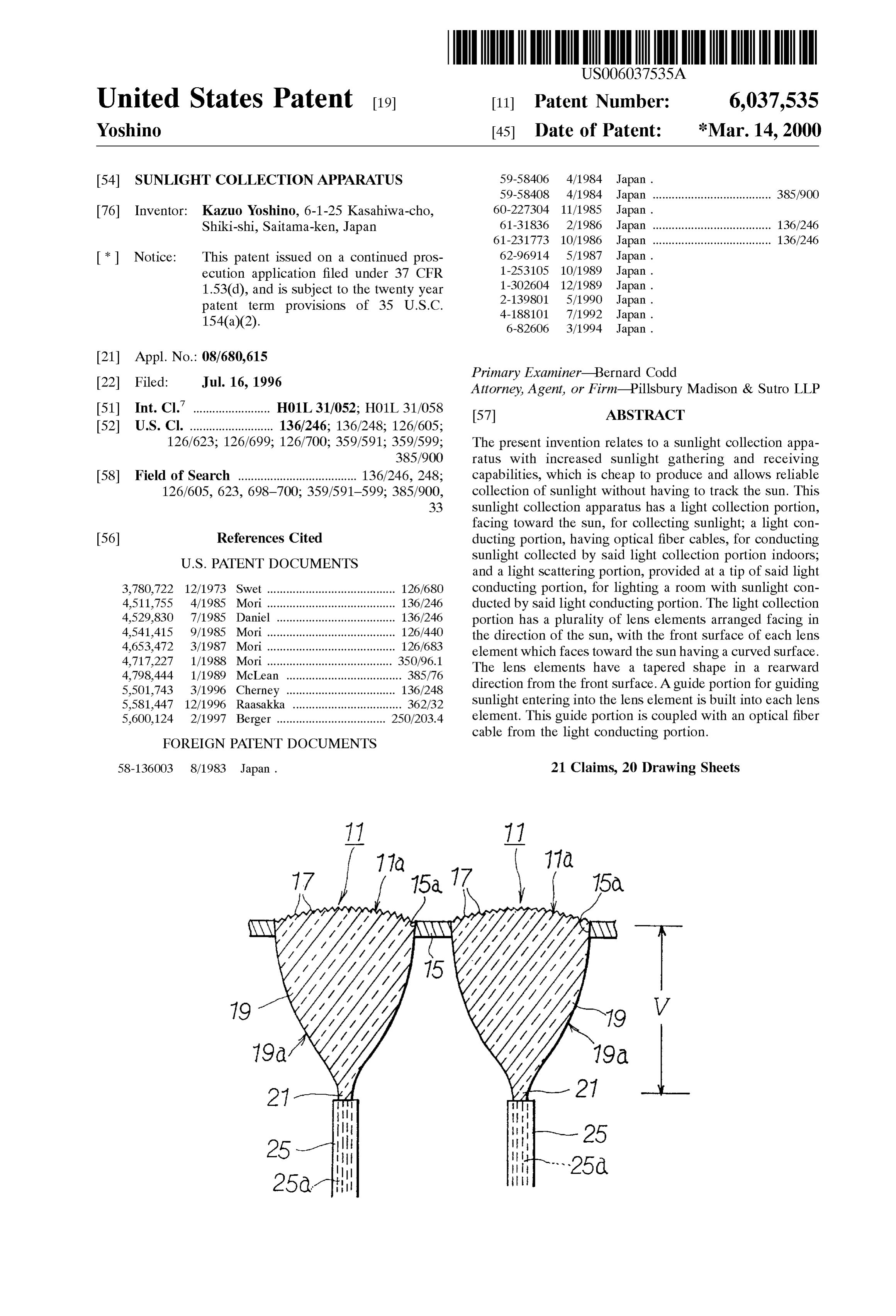
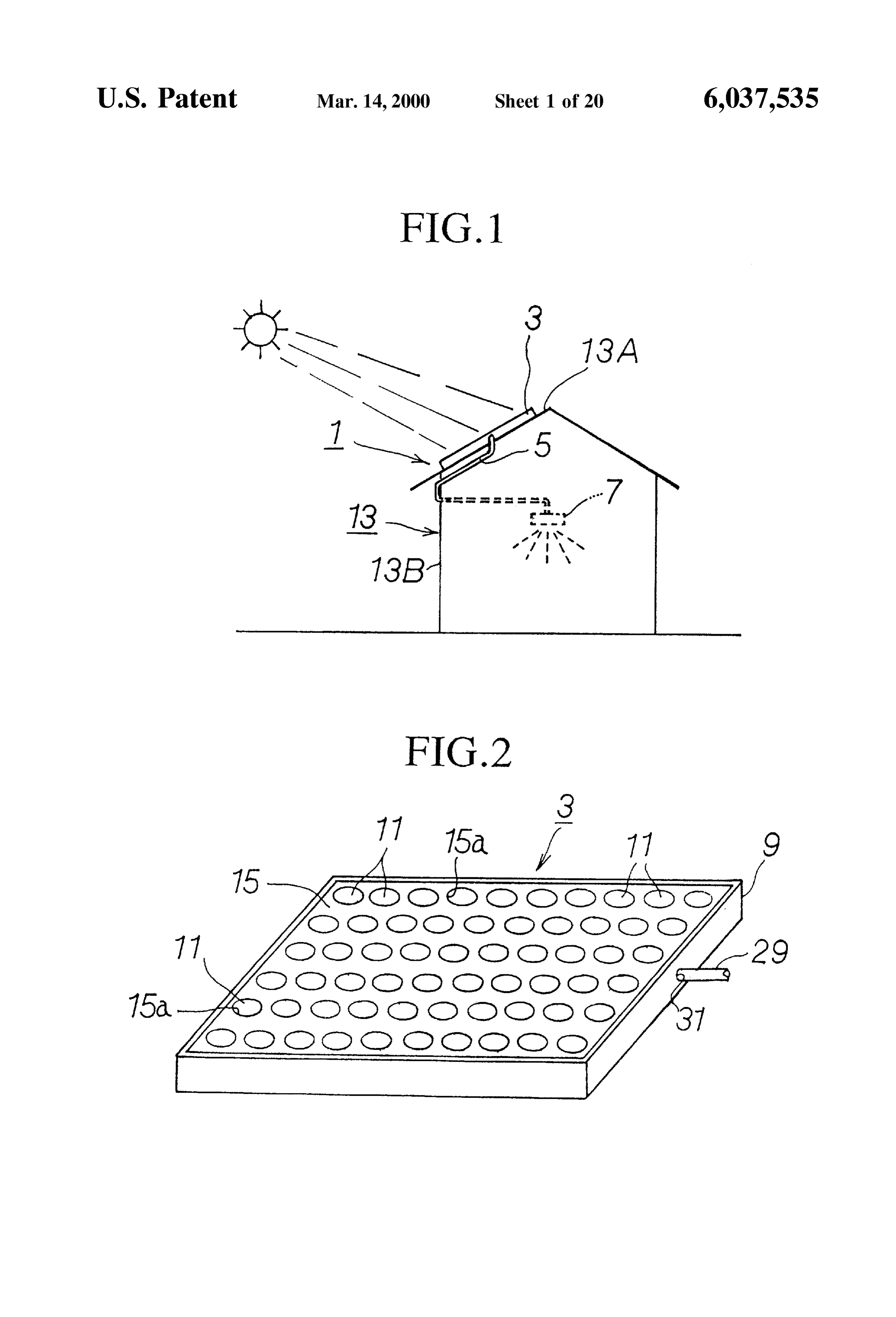
of the guide portion built into the lens element So as led to the rear end of the guide portion, then the light tioned above have a structure wherein a lens element having is conducted from the rear end of the guide portion to the a Solar tracking device focuses Sunlight at the focal point of core of an optical fiber cable from the light conducting the lens element While tracking the Sun, the Sunlight is portion. The light which has been guided into the core of the guided to the required room through an optical fiber cable optical fiber cable is Scattered by a light Scattering portion having one end Surface positioned at the focal point of the 35 connected to the end of the optical lens element, and the room is lit by the Sunlight by means of illuminate the room of a building. fiber cable So as to a light Scattering material provided at the other end of the optical fiber cable. BRIEF DESCRIPTION OF THE DRAWINGS However, the above-mentioned conventional Sunlight col lection apparatuses have the following problems. With 40 FIG. 1 is a schematic illustration showing the first regard to type (1), the installation work can be complicated embodiment of the Sunlight collection apparatus according because the light conducting Section is formed from ducts, to the present invention.
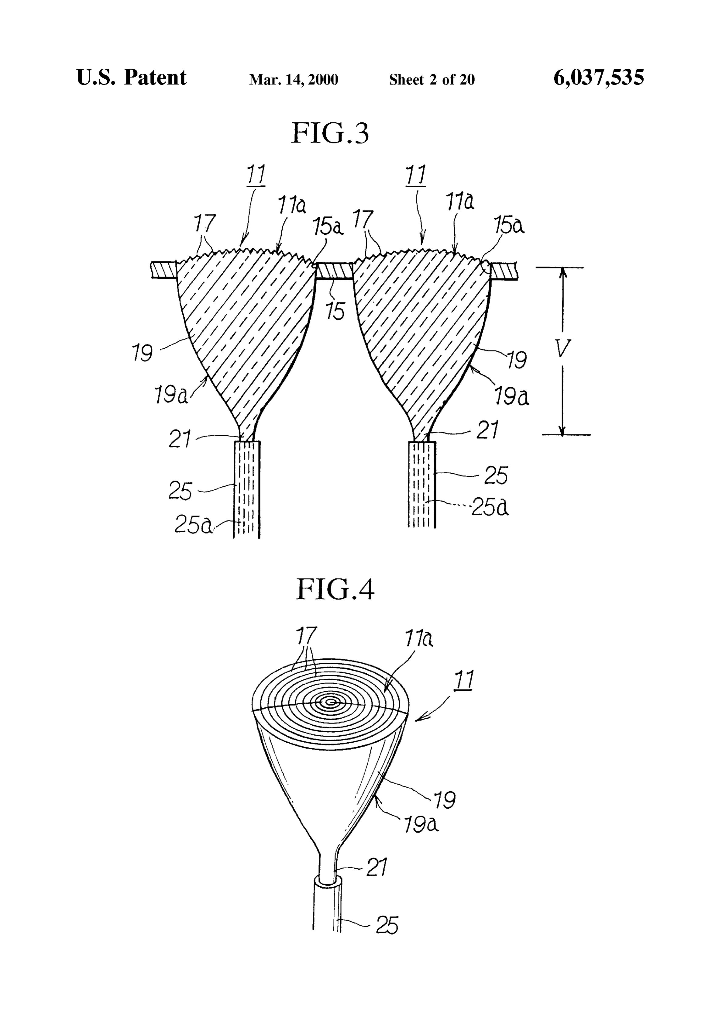
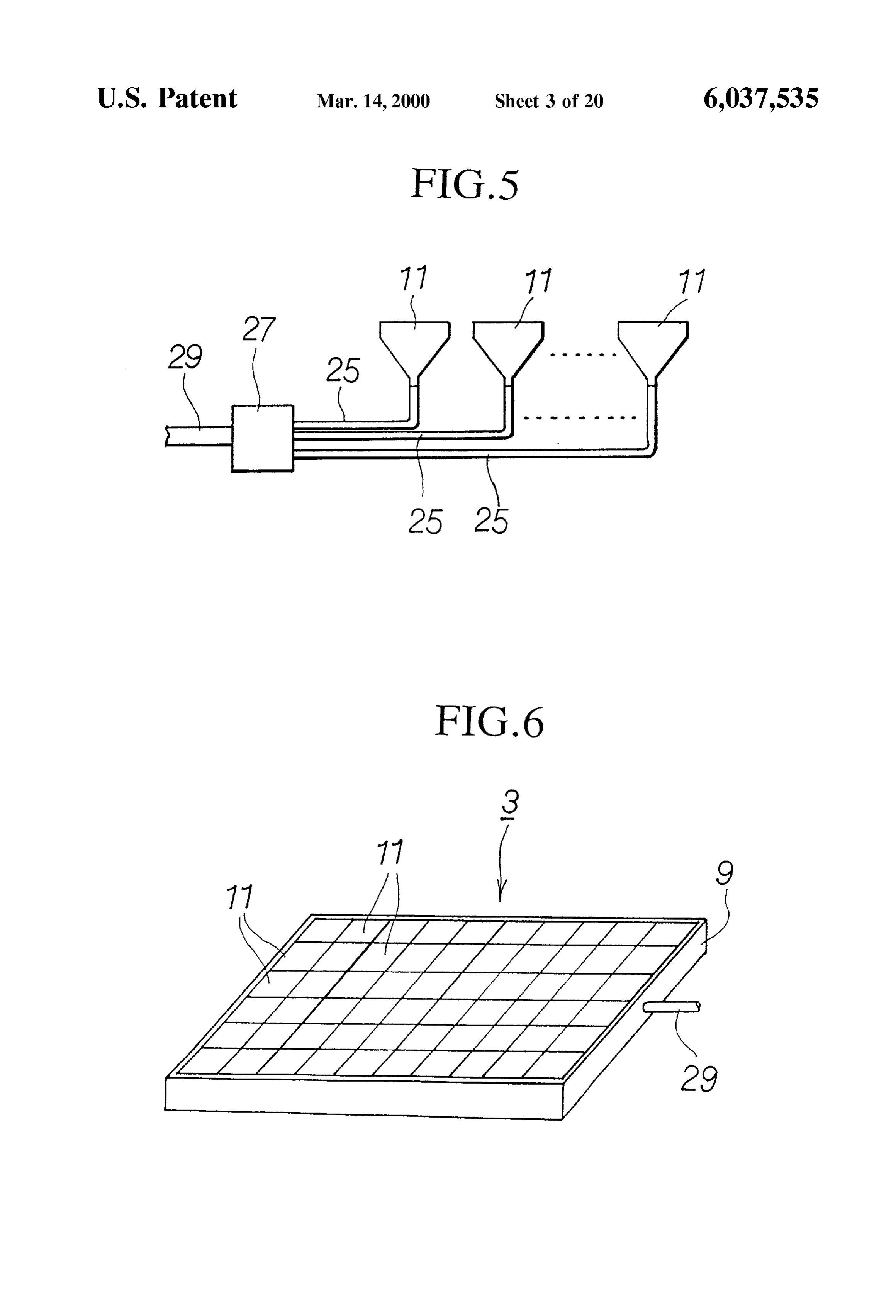
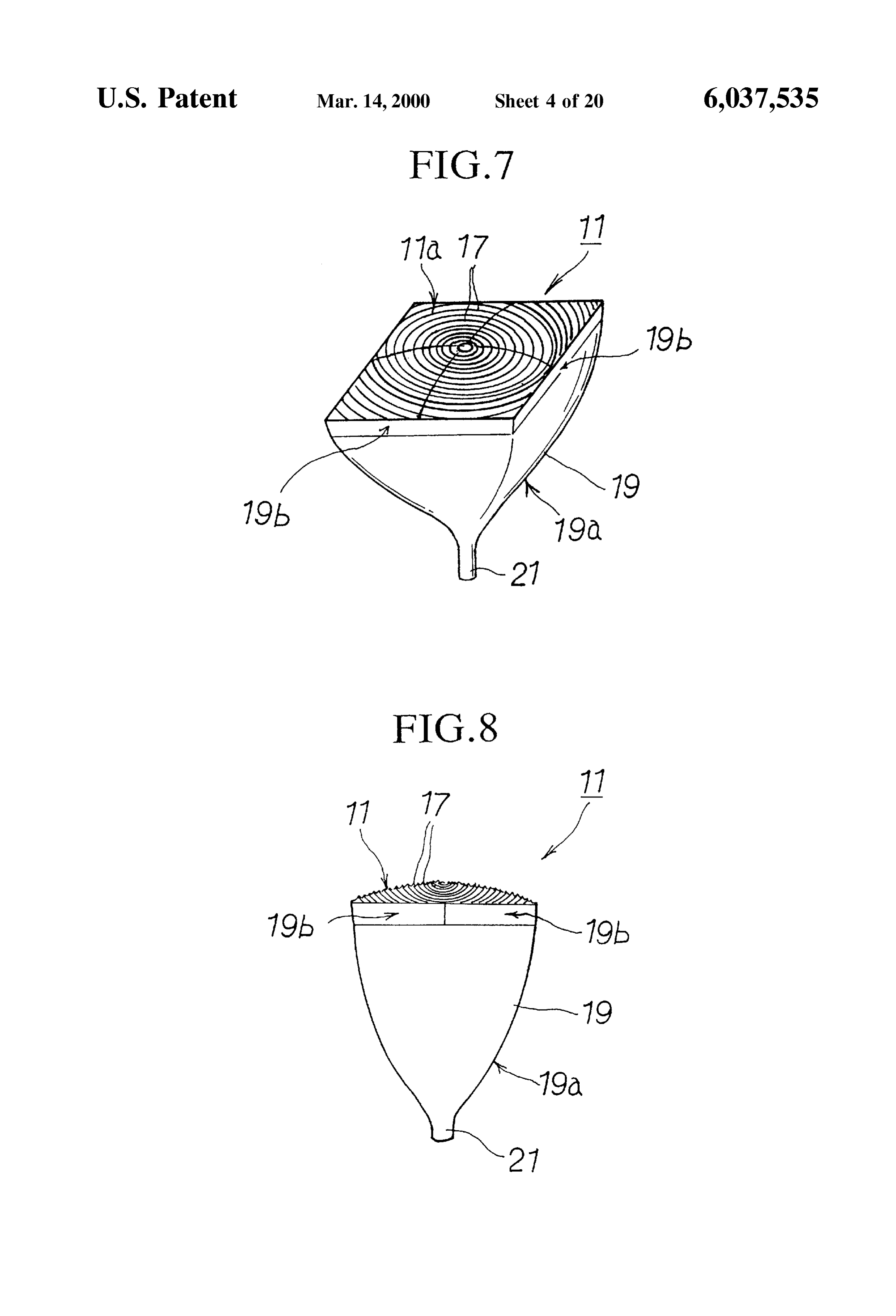
So that a portion of the building must be destroyed in order FIG. 2 is a perspective view showing the light collection to install the apparatus in a building which is already Section of the Sunlight collection apparatus. Standing, thus greatly increasing the cost and inflating the 45 FIG. 3 is a vertical section view showing a lens element. price of installation. FIG. 4 is a perspective view showing a lens element. With regard to type (2), the light conducting Section is FIG. 5 is a schematic illustration showing the connection able to be easily installed in buildings because the light structure conducting Section is formed from optical fiber cables, but cable. of optical fiber cables with a main optical fiber the light collection Section has a large lens element and a 50 FIG. 6 is a perspective view showing the collection tracking device for tracking the Sun, So that the Support
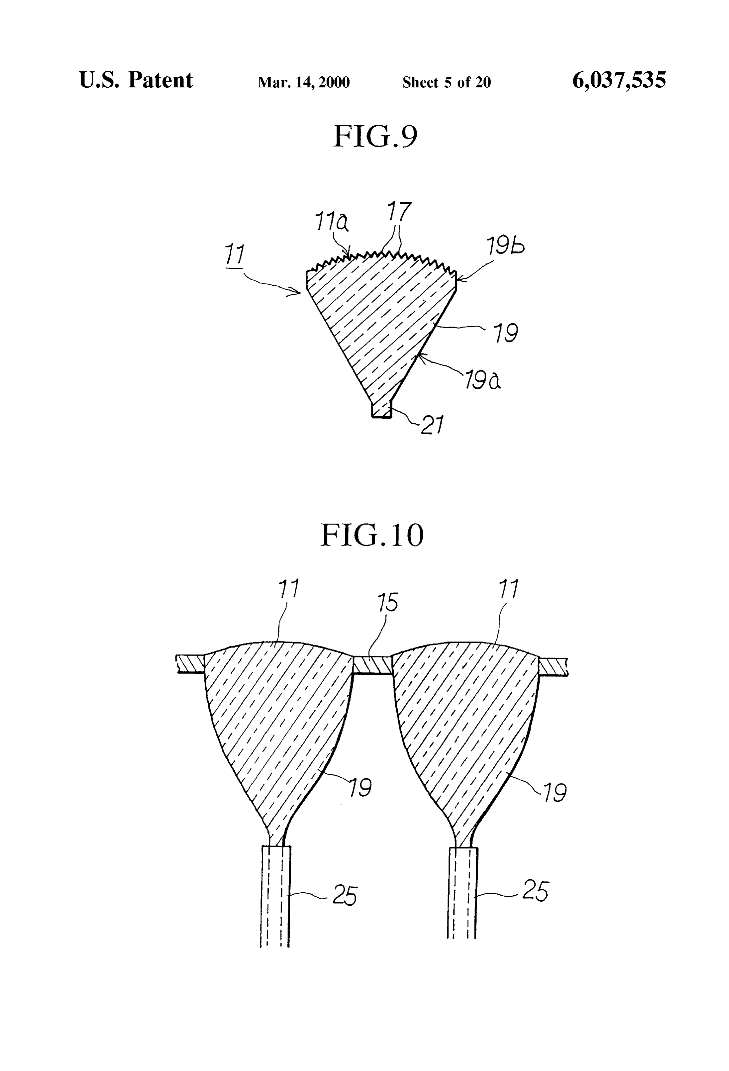
Structures for holding the lens element and the tracking Section of the Second embodiment of the present invention. device must be complicated, thereby greatly increasing the FIG. 7 is a perspective view showing a lens element. cost and making the price too high for general purposes. FIG. 8 is a vertical section view showing a lens element. Additionally, with regard those types which track the Sun, 55 FIG. 9 is a vertical section view showing a modification the Structure must be Such as to position the end Surface of example of a lens element.
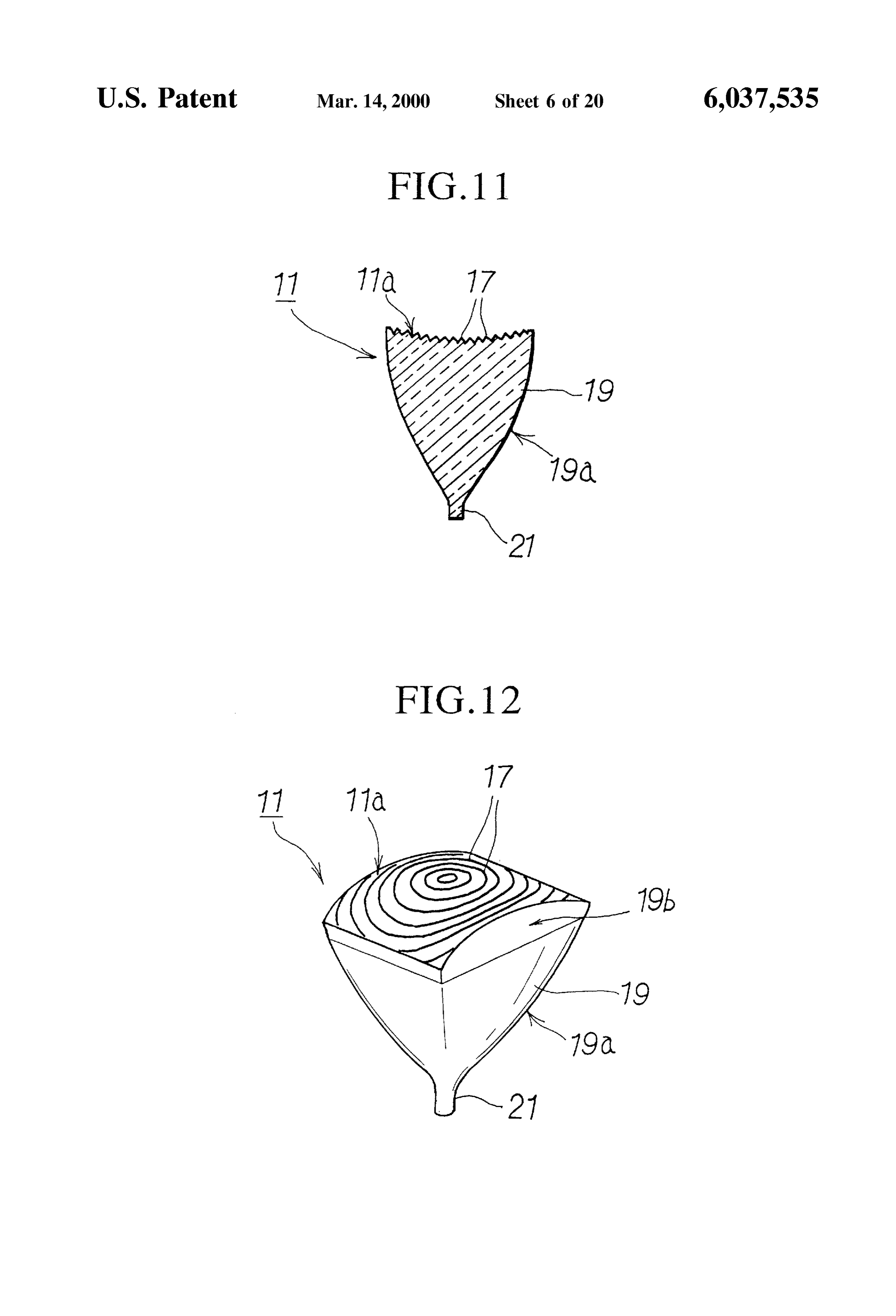
the optical fiber cable of the light conducting Section at the FIG. 10 is a vertical section view showing lens elements focal point of a large-diameter lens element and continually with convex front Surfaces.
track the Sun in order to maintain the Sun on the optical axis 60 FIG. 11 is a vertical section view showing a lens element of the lens element So that the Sunlight can be gathered and with a concave front Surface.
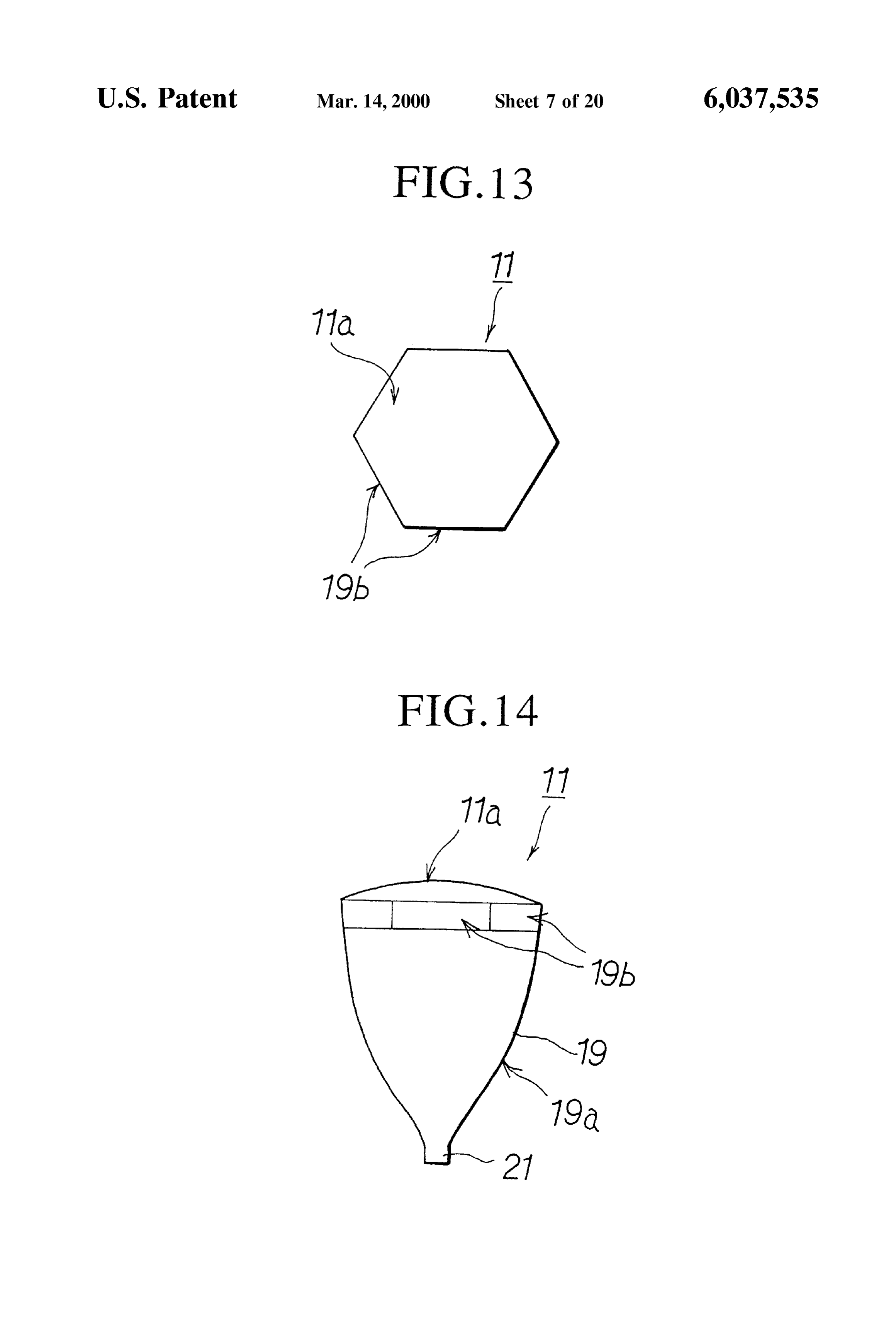
received at the focal point on the end Surface of the optical FIG. 12 is a perspective view showing a lens element fiber cable. Therefore, the tracking device is extremely costly and requires extreme precision to track the Sun. wherein the front surface is formed into a cylindrical curved Surface.
SUMMARY OF THE INVENTION 65 FIG. 13 is a plan view showing a lens element wherein the The present invention has the object of offering a Sunlight front Surface is hexagonal and Fresnel rings are formed on collection apparatus, with Superior Sunlight gathering and the front Surface.
Page 23
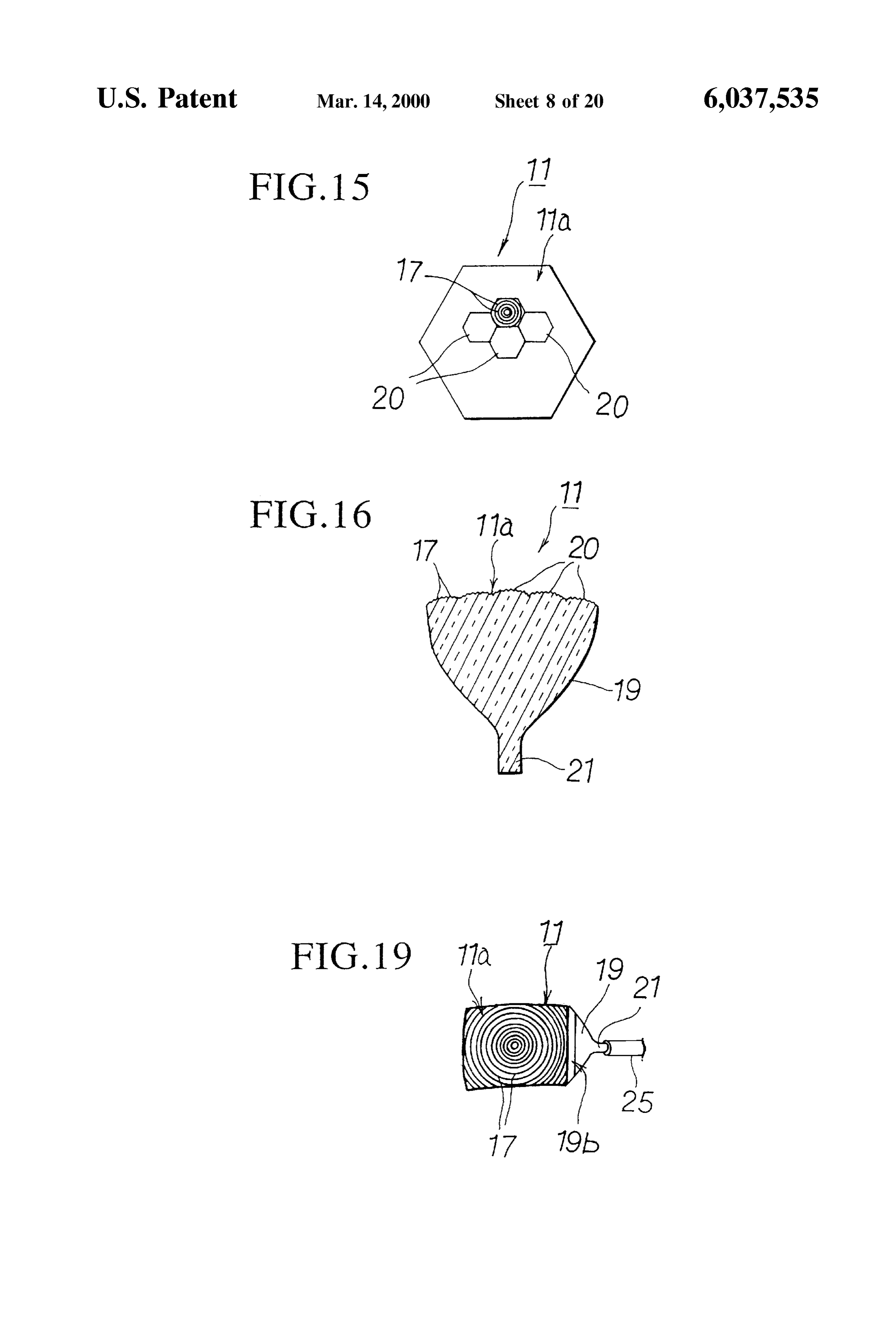
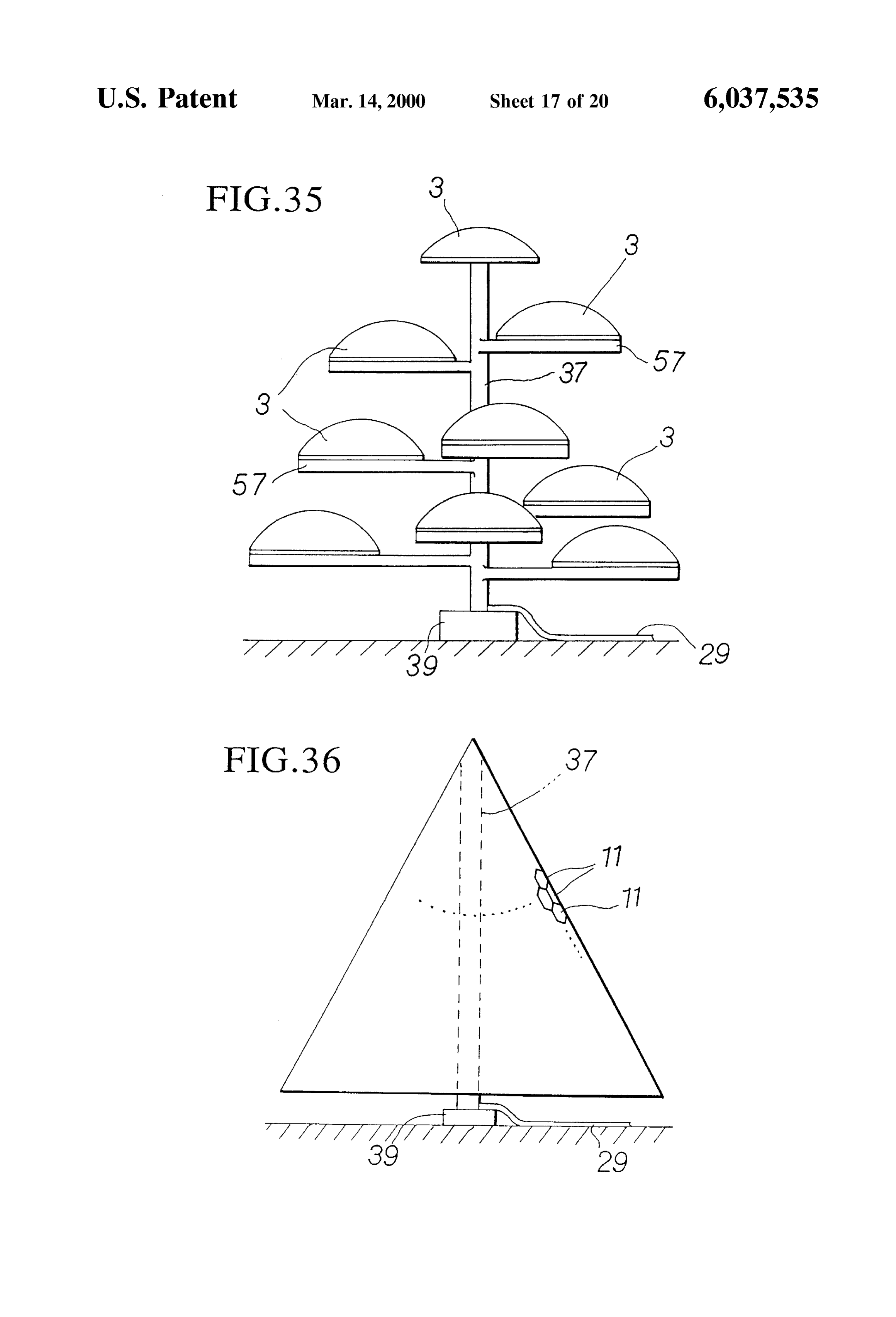
FIG. 14 is a vertical section view of a lens element FIG. 36 is a front view showing a ninth embodiment of a wherein the front Surface is hexagonal and Fresnel rings are light collection Section according to the present invention, formed on the front Surface. showing a tree-type light collection Section wherein a plu FIG. 15 is a plan view of a lens element wherein the rality of hexagonal light collection Sections are arranged into convex front Surface is hexagonal and a plurality of hex a tree form.
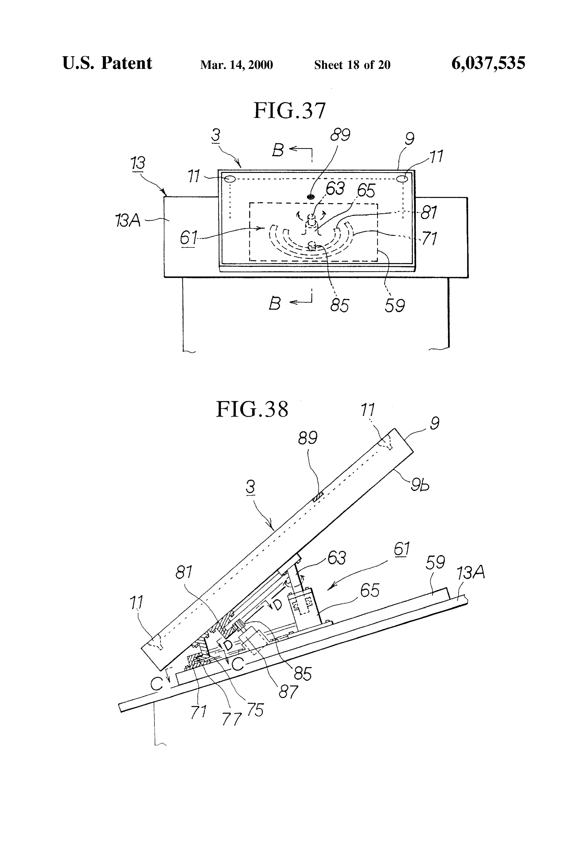
agonal Fresnel lenses are formed on the front Surface. FIG.37 is a front view of a light collection section having FIG. 16 is a vertical section view of a lens element a Solar tracking device.
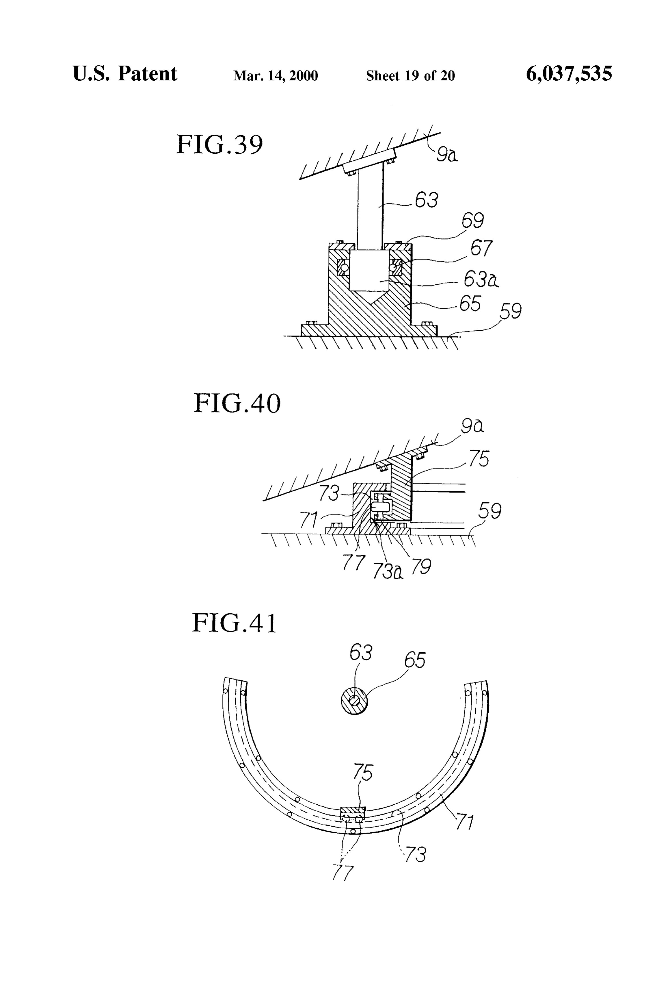
wherein the convex front Surface is hexagonal and a plural FIG.38 is a section view along the line 38–38 in FIG. 37 ity of hexagonal Fresnel lenses are formed on the front showing a light collection Section having a Solar tracking Surface. device.
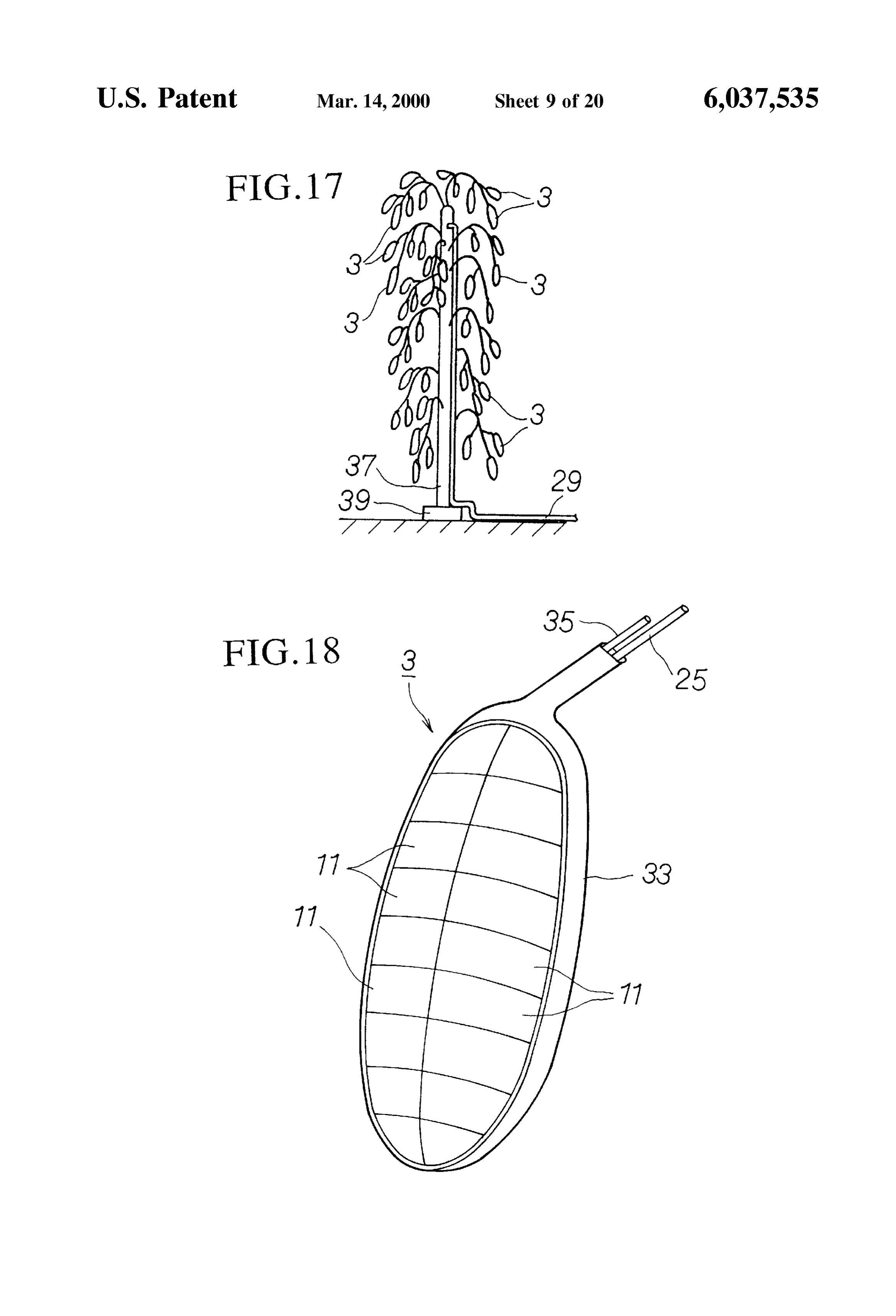
FIG. 17 is a front view showing a tree-type light collec FIG. 39 is an enlarged section view showing a rotational tion Section wherein a plurality of light receiving Sections axle and an axle Support Section.
are arranged into a tree shape, according to the third embodi FIG. 40 is an enlarged Section view showing a guide and ment of the light collection Section of the present invention. 15 a guide roller.
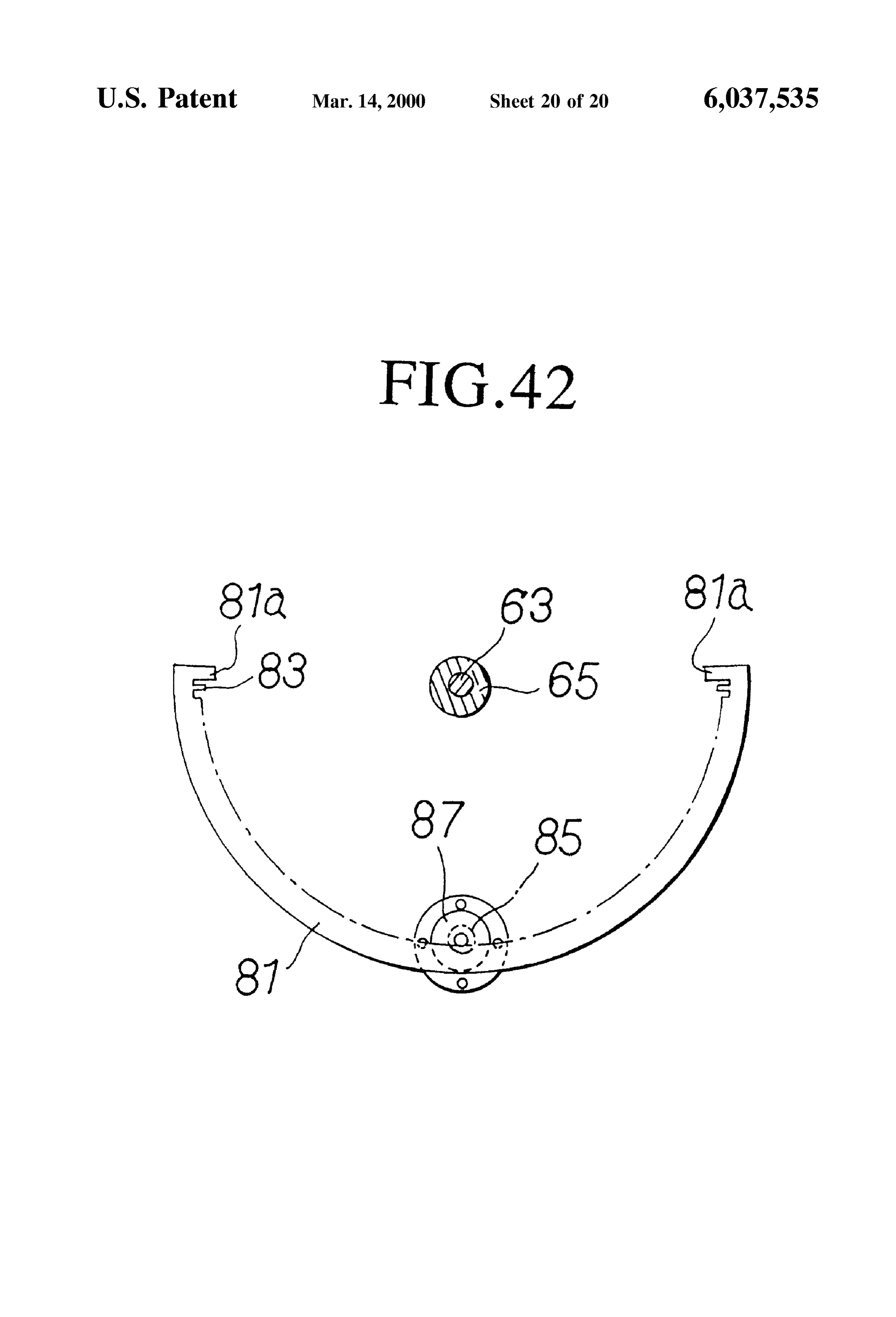
FIG. 18 is a perspective view showing a light collection FIG. 41 is a section view along the line 41-41 in FIG.38 Section. showing a guide and a guide roller. FIG. 19 is a perspective view showing a lens element FIG. 42 is a section view along the line 42-42 in FIG.38 taken from a portion of the light collection Section. showing a ring-shaped rack and a pinion provided on a FIG. 20 is a plan view showing a light collection section motor.
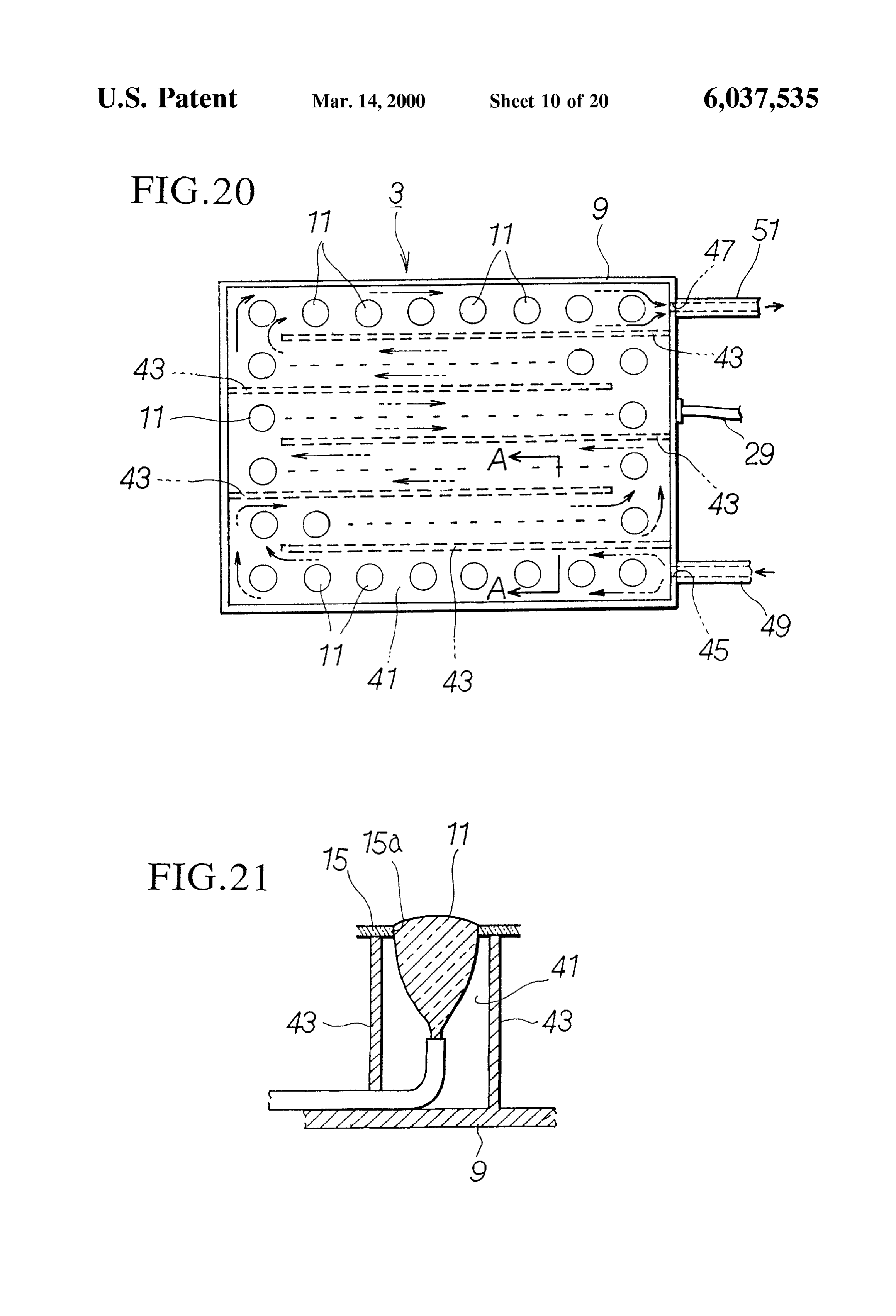
having a water route according to the fourth embodiment of the present invention. PREFERRED EMBODIMENTS OF THE FIG. 21 is a section view along the line 21-21 in FIG. 20 INVENTION showing the water route. Hereinbelow, the preferred first embodiment of the FIG. 22 is a vertical Section view showing a light collec 25 present invention will be explained with reference to the tion Section having Solar batteries according to the fifth drawings.
embodiment of the present invention. AS shown in FIG. 1, the Sunlight collection apparatus 1 FIG. 23 is a vertical section view showing a light collec comprises a light collection Section 3 for gathering Sunlight, tion Section having Solar batteries according to the Sixth a light conducting Section 5 for guiding the Sunlight gathered embodiment of the present invention. at the light collection Section 3, and a light Scattering Section FIG. 24 is a perspective view showing another embodi 7 for Shining the Sunlight guided by the light conducting ment for the Structure of a lens element of the light collection Section 5 indoors.
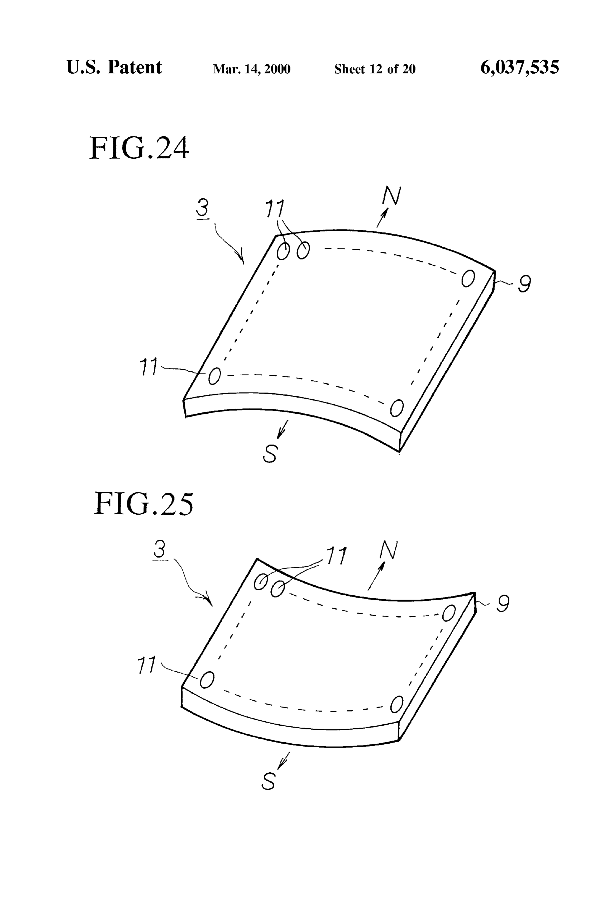
Section, showing a light collection Section wherein a plural As shown in FIG. 2, the light collection section 3 has a ity of lens elements are arranged laterally acroSS a curved 35 rectangular case 9 having a designated depth. A plurality of Surface which protrudes outward. lens elements 11 formed into Small-diameter circles with the FIG. 25 is a perspective view showing a light collection front Surfaces 11a (FIG. 3) acing the Sun are arranged inside Section wherein a plurality of lens elements are arranged the case 9 toward the upper portion of the case 9, which can, laterally acroSS a curved Surface which indents inward. for example, be installed at a designated angle of inclination FIG. 26 is a perspective view showing a light collection 40 facing Southwards on a rooftop 13A of a building 13. The Section wherein a plurality of lens elements are arranged case 9 is a thin box with an open upper portion, to the top Vertically acroSS a curved Surface which protrudes outward. of which a support panel 15 has been affixed as shown in FIG. 27 is a perspective view showing a light collection FIG. 3. Support holes 15a into which the lens elements 11 Section wherein a plurality of lens elements are arranged can fit are formed on this Support panel 15. The Support Vertically acroSS a curved Surface which indents inward. 45 holes. 15a are provided at positions of arrangement of the FIG. 28 is a side view showing a light collection section lens elements 11, and the lens elements 11 are affixed to the installed on a Side wall of a building which receives Sunlight. support panel 15 by fitting the lens elements 11 into these FIG. 29 is an enlarged section view showing a state of support holes 15a.
attachment of a lens element. Each lens element 11 may, for example, be formed from 50 glass or plastic materials with the front Surfaces of circular
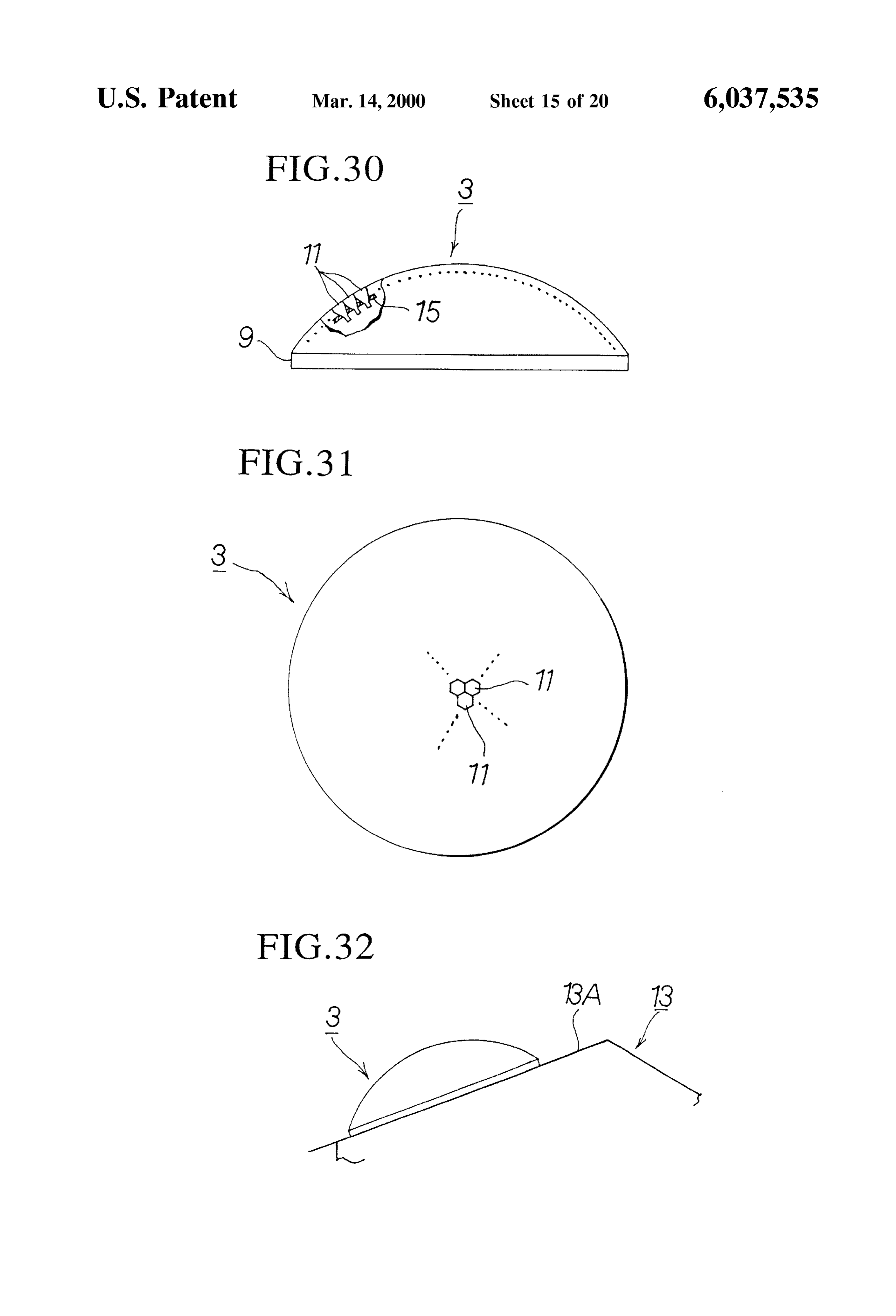
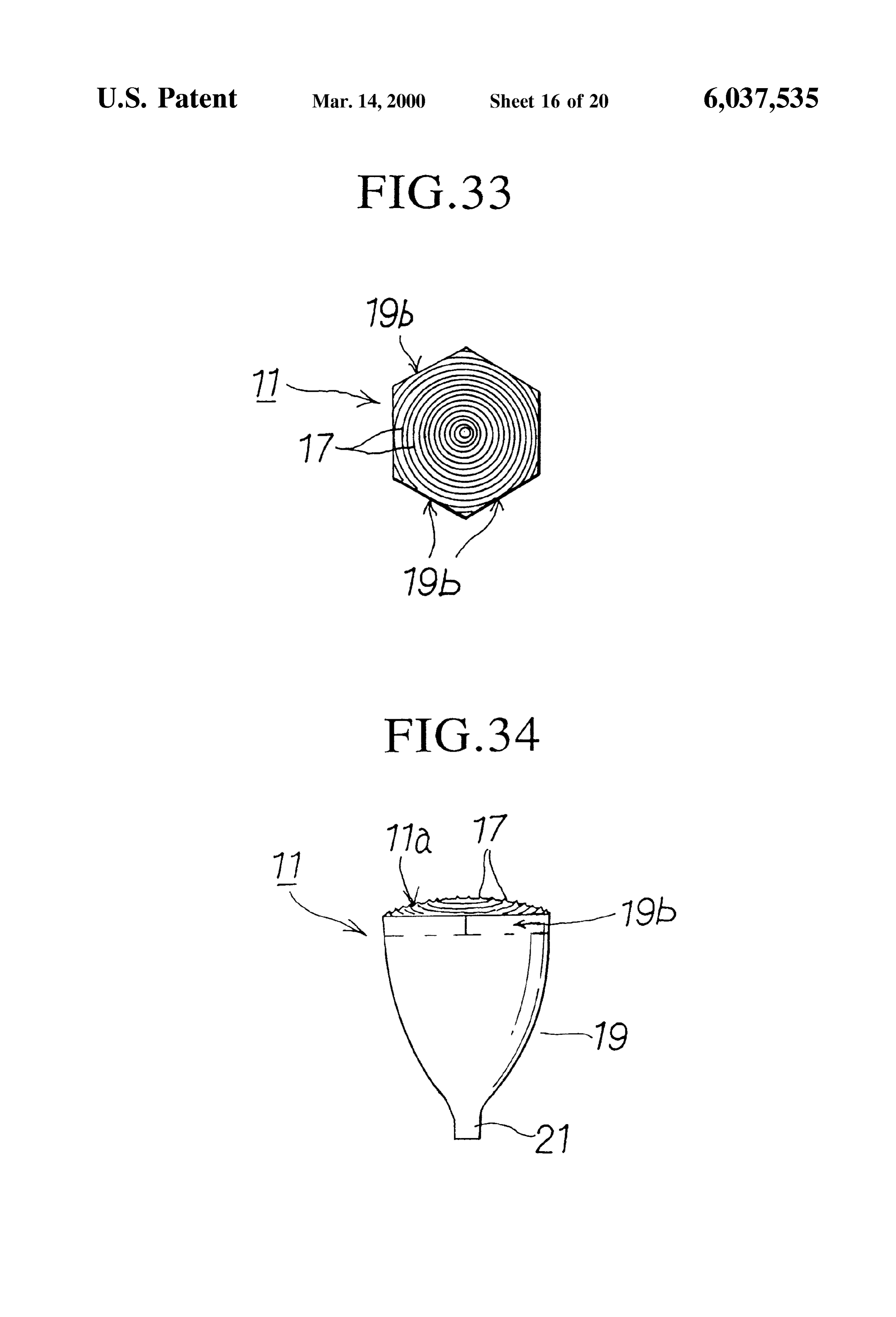
FIG. 30 is a side view showing a seventh embodiment of a light collection Section according to the present invention, form with Small diameters of less than approximately 10 cm. showing a light collection Section wherein a plurality of lens lensAs shown in FIGS. 3 and 4, the vertical cross-section of each is Such that the front Surface 11a of the element 11 is elements are arranged in a dome shape. formed into a spherical Surface which protrudes outward. FIG. 31 is a plan view of a dome-shaped light collection 55 Fresnel rings 17, having diameters which gradually become Section.
larger from the center to the periphery, are formed on this
FIG. 32 is a side view showing a dome-shaped light Spherical Surface 11a, So that the front portion of the lens collection Section installed on the rooftop of a building. element 11 forms a Fresnel lens. In the present embodiment, FIG. 33 is a plan view showing a lens element having a the guide portion 19 and the connection Section 21 are hexagonal planar shape. 60 formed so that the focal point of this type of lens element 11 FIG. 34 is a side view showing a lens element having a is positioned inside the connection Section 21 formed uni hexagonal planar shape. tarily with the guide portion 19 of a solid material. The front FIG. 35 is a front view showing an eighth embodiment of surface 11a of the lens element 11 is not restricted to being a light collection Section according to the present invention, Spherical, and may be a curved Surface having any radius of showing a tree-type light collection Section wherein a plu 65 curvature. Consequently, the light gathering capability of the rality of dome-shaped light collection Sections are arranged lens element 11 increases and the focal length of the lens into a tree form. element 11 shortens because the front Surface 11a of the lens
Page 24
S 6 element 11 protrudes outward and Fresnel rings 17 are explained. When Sunlight hits each lens element 11 in the provided on the front surface 11a, so that the depth dimen light collection portion 3 installed at a designated angle of sion V of the guide portion 19 in the lens element 11 can be inclination on the southward roof 13A of a building 13, each made Smaller than usual. lens element 11 functions as a strong convex lens due to the The rear portion of each lens element 11 is unitarily shape of the front Surface 11a having a bulging curved formed into a guide portion 19 which guides the light surface and the formation of a Fresnel lens provided with entering from the front surface 11a of the lens member 11, Fresnel rings on the front Surface 11a, So that each lens and a connection portion 21 is unitarily formed on the guide element 11 is able to gather Sunlight from a wide range. The portion 19. That is, as shown in FIG. 3, the guide portion 19 Sunlight entering through the front Surface 11a of each lens of the lens member 11 are formed into approximate conical element 11 is collected at the connection portion 21 of the Surfaces which are tapered in the direction toward the rear guide portion 19, conducted to the rear end of the guide portion of the lens element 11 from the front Surface 11a, and portion 19 by reflecting off the circumferential surface 19a the circumferential Surface 19a is formed into a convex of the guide portion 19 provided unitarily with the lens curved surface which protrudes outward from the front element 11, and led from the connection portion 21 formed Surface 11a to the rear end.
15 at the rear end of the guide portion 19 to the core 25a of the
A reflective material (not shown in the drawings) is coated optical fiber cable 25.
onto the circumferential surface 19a of the guide portion 19 In this case, the front Surface 11a of the lens element 11 and the connection portion 21 So that the inner Surface has a Spherical shape which bulges outwards, and the front becomes a mirror Surface and the Sunlight entering the guide Surface 11a also has a Fresnel lens, So that the light gathering portion 19 is not able to pass through. The circumferential capability is markedly increased, and it is possible to gather surface 19a of the guide portion 19 is formed with a convex Sufficient Sunlight even when the height of the Sun largely curved Surface which bulges outward as mentioned above So differs between Summertime and wintertime, and when the that the light entering into the lens element 11 from the front angle of the Sun changes between dawn and dusk within a surface 11a of the lens element 11 will not escape through single day. The guide portion 19 of the lens element 11 has the front Surface 11a of the lens element 11 due to the 25 an approximately conical Surface which taperS in the rear reflective angles for reflecting the Sunlight off the inner ward direction, and the circumferential Surface 19a of this surface of the guide portion 19 in the lens element 11 being guide portion 19 has a curved shape which bulges outward; Small. In this way, as much as possible of the light entering therefore, the light entering into the lens element 11 from the the front surface 11a of the lens element 11 is captured by front surface 11a of the lens element 11 can be reliably the optical fiber cable 25 of the light conducting section 5, conducted to the optical fiber cable even if the Sun is not thereby increasing the receiving capabilities. aligned with the optical axis of the lens element 11. Thus, the The rear end of the guide portion 19 of the lens element light receiving capability of the lens element is increased 11 has a designated diameter; that is, the outer diameter is because the light which has entered into the lens element 11 made equal to the diameter of the core 25a of an optical fiber can be largely prevented from eScaping back through the cable 25 having a bundle of a plurality of optical fibers, and 35 front surface 11a of the lens element 11. Additionally, the the cylindrical connection Section 21 is formed unitarily focal length of the lens element is shortened due to the with the guide portion 21. One end surface of the core 25a outwardly bulging spherical shape of the front Surface 11a of of the optical fiber cable 25 having a bundle of a plurality of the lens element 11 and the Fresnel lens formed at the front optical fiberS is connected to the connection portion 21 of the surface 11a, so that the depth dimension V of the lens guide portion 19. As for the method of connecting the 40 element 11 can be made Shorter. As a result, the weight of the connection portion 21 of the guide portion 19 with the end lens element 11 can be made lighter even if the guide portion surface of the core 25a of the optical fiber 25, the connection 19 is made unitarily with the lens element 11. can be made by using a conventional optical fiber connector The light which has been conducted to the core 25a of the (not shown in the drawings). The connection can also by optical fiber cable 25 coupled to the connection portion 21 made by fusing the end Surface of the connection portion 21 45 of the guide portion 19 of each lens element 11 passes of the guide portion 19 with the end Surface of the core 25a through each optical fiber cable 25 and is further conducted of the optical fiber cable 25. to the main optical fiber cable 29 by way of a connector. The As shown in FIG. 5, each optical fiber cable 25 coupled light Scattering portion 7 connected to the other end of the to the guide portion 19 of a lens element 11 is connected to main optical fiber cable 29 then scatters light inside a room a main optical fiber cable 29 by means of a special connector 50 of the building 13.
27 inside the case 9. This main optical fiber cable 29 is led Therefore, in the present embodiment, the front Surface of outside through a through hole 31 provided in the case 9 as each lens element has an outwardly bulging curved Surface shown in FIG. 2. and a Fresnel lens is formed on the curved front Surface, So The main optical fiber cable 29 led out of the case 9 can, that the light gathering capabilities are largely increased, for example, be installed along the side wall 13B from the 55 allowing Sufficient Sunlight to be collected even if the height roof 13A of a building 13, and be led to the required room of the Sun largely differs between Summertime and winter by passing through the side wall 13B, as shown in FIG. 1. time and allowing light to be reliably collected when the Sun Inside the room, a light Scattering portion 7, formed from is at a low angle Such as at dawn or at dusk during a single glass or plastic, which Scatters and radiates the light, is day. As a result, reliable light collection is possible without attached to the other end Surface of the core of the main 60 using a Solar tracking device, thereby allowing cheap con optical fiber 29. Consequently, the Sunlight conducted by Struction. Since the guide portion of the lens element has an means of the optical fiber cables 25 and 29 is able to shine approximately cylindrical shape which tapers in the rear and fill the room. The light conducting section 5 is formed ward direction and the circumferential Surface of this guide from a plurality of optical fiber cables 25 and the main portion has a curved shape which bulges outwardly, the light optical fiber cable 29. 65 entering the lens element from the front Surface of the lens Next, the operation of the Sunlight collection apparatus element is reliably conducted to the coupled optical fiber according to the above-described Structure will be cable even if the Sun is not aligned with the optical axis of
Page 25
the lens element, So that the light which has entered the lens The Vertical cross-sectional shape and the planar shape of element is largely prevented from escaping through the front the lens elements 11, 11", 11", 11", 110, 111, 211, 311, 411, Surface of the lens element, thereby increasing the light and 511 are not restricted to the above examples, and Similar receiving capability. Since the front Surface of the lens effects can be obtained by the following structures. element has a curved shape which bulges outwardly and a 1) The shape of the circumferential surface 19a" of the Fresnel lens is formed on the curved front Surface, the focal guide portion 19" of the lens element 11" can be made length of the lens element is made shorter, thereby allowing purely conical, or the circumferential Surface of the guide the depth dimension of the lens element to be made Smaller. portion 19" can be made So as to combine a conical Surface AS a result, the weight of the lens element can be reduced with a contact surface portion 19b" formed at the front even if the guide portion is formed unitarily with the lens portion, as shown in FIG. 9. In these cases, the receiving element. Since the light conducting Section 5 is formed from capability is Somewhat reduced, but the resulting effect is optical fiber cables, the installation work is not complicated Similar.
as with conventional duct-type configurations, So as to allow 2) As for the shape of the front surface 110a of the lens easy attachment. element 110, it is possible to have an outwardly bulging The second embodiment of the light collection section curved surface without Fresnel rings as shown in FIG. 10, to according to the present invention will be explained with 15 have an inwardly indented curved surface without Fresnel reference to the drawings. FIG. 6 is a perspective view rings (not shown in the drawings), to have an inwardly showing a light collection Section of the present indented curved surface having Fresnel rings 117 formed on embodiment, and FIG. 7 is a perspective view showing a the front Surface 110a as shown in FIG. 11. The planar lens element. In the present embodiment, the light collection shapes of these examples are not restricted to being circular, Section 3' of the Sunlight collection apparatuS 1 has a and it is possible to have elliptical or polygonal shapes as different structure. That is, as shown in FIG. 6, the light well. When the structure is such as to have an inwardly collection Section 3' of the present embodiment has a plu indented curved surface having Fresnel rings 117 formed on rality of lens elements 11' arranged within a rectangular case the front surface 111a as shown in FIG. 11, the guide portion 9, each lens element 11" having a planar shape wherein the 119 of the lens element is tapered in a rearward direction and planar Surface of the case 9 facing the Sun is divided into a 25 the circumferential Surface 119a has a curved shape which plurality of identical shapes. While the front surface of the bulges outward, So that the angle of reflection of the Sunlight case has been divided into rectangles in the present entering the guide portion 119 through the front surface 111a embodiment, the shapes are not restricted thereto, So that the of the lens element 111 is made Small. As a result, the Surface may be divided into other shapes, Such as polygons, Sunlight is more reliably guided to the connection portion triangles or hexagons, and the shape of the front Surface of 121, and it becomes possible to reliably gather the light So each lens element 11" can be formed into a corresponding that the Sunlight receiving capability is able to be compara planar shape. tively increased.
For example, the planar Shape of each lens element 11" can 3) While the front surface 11 of the lens element 11 was be made Square and the lens elements 11" can be arranged in made mutually adjacent fashion without gaps, as shown in FIGS. 35 Surfaceintois either a conveX or concave spherical Surface, the not necessarily restricted to being spherical, So 6 and 7. As shown in FIGS. 7 and 8, each lens element 11" has a front Surface facing the Sun which bulges outwardly that the Surface 211a may be a different type of curved with a spherical shape and has Fresnel rings 17" which Surface, for example a cylindrical Surface as shown in FIG. 12. That is, the front Surface 2.11a of the lens element 211 become gradually larger from the center to the periphery So may be a cylindrical curved Surface, So that it becomes as to form a Fresnel lens on the lens element 11", as with the previous embodiment. As shown in FIG. 8, a contact surface 40 possible to gather as much Sunlight as possible even when portion 19b' corresponding to each Side of the planar Square the Sun is at a low angle during the wintertime or when the is provided around the front portion of the guide portion 19 Sun is positioned to the east or west, by orienting the axis of of each lens element 11" as shown in FIG. 8, so as to allow the cylindrical Surface vertically or laterally. adjacent lens elements to contact each other. Consequently, 4) The planar shape of the lens elements is not necessarily it is possible to obtain the Same effects as with the previous 45 restricted to being round or rectangular as in the above embodiment, while allowing more Sunlight to be collected mentioned embodiments, and may be hexagonal as shown in by filling in the gaps between the lens elements. FIGS. 13 and 14 or FIGS. 15 and 16. The lens element 211 Next, other embodiments of a lens element according to shown in FIGS. 13 and 14 has a planar shape which is the present invention will be explained with reference to the hexagonal, wherein the front Surface 311a is convex, the drawings. FIG. 9 is a vertical section view showing a 50 front Surface 311a has Fresnel rings, and contact Surface modification example of a lens element. FIG. 10 is a vertical portions 319b are formed around the front portion of the Section view showing lens elements with convex front guide portion 319. These lens elements 311 are capable of Surfaces. FIG. 11 is a vertical Section view showing a lens being arranged in a honeycomb pattern. The lens element element with a concave front Surface. FIG. 12 is a perspec shown in FIGS. 15 and 16 has a hexagonal planar shape, tive view showing a lens element wherein the front Surface 55 wherein hexagonal curved surfaces 420 and 520 bulge is formed into a cylindrical curved surface. FIG. 13 is a plan outward from the convex front Surface 411a and 5.11a, and View showing a lens element wherein the front Surface is Fresnel ringS 417 are formed on each hexagonal curved hexagonal and Fresnel rings are formed on the front Surface. surface 420. Consequently, similar effects are able to be FIG. 14 is a vertical section view of a lens element wherein obtained by the lens element shown in FIGS. 13 and 14, the front Surface is hexagonal and Fresnel rings are formed 60 while the lens elements shown in FIGS. 15 and 16 increase on the front surface. FIG. 15 is a plan view of a lens element the light gathering capabilities by providing a plurality of wherein the convex front Surface is hexagonal and a plural hexagonal convex Surfaces and Fresnel rings on the lens ity of hexagonal Fresnel lenses are formed on the front element. Alternatively, the front surface of the lens may be Surface. FIG. 16 is a vertical section view of a lens element flat or concave instead of being a curved Surface which wherein the convex front Surface is hexagonal and a plural 65 bulges outwardly.
ity of hexagonal Fresnel lenses are formed on the front The third embodiment of the light collection section Surface. according to the present invention will be explained with
Page 26
reference to the drawings. FIG. 17 is a front view showing means of a connector along with the optical fiber cables 725 a tree-type light collection Section wherein a plurality of of the light collection sections 73 of other branches. The light receiving Sections are arranged into a tree shape, main optical fiber cable 29 from the pole 37 follows the according to the third embodiment of the light collection ground or the wall of a building to lead to the designated section of the present invention. FIG. 18 is a perspective room, and the inside of the room is lit by means of the light view showing a light collection section. FIG. 19 is a per scattering portion 7 provided at the tip of the optical fiber Spective view showing a lens element taken from a portion cable 29. The number of light collection sections 73 attached of the light collection Section. According to the present to the pole can be any arbitrary number depending upon the embodiment as shown in FIG. 17, the light collection section Size of the room, as long as adequate light is obtained in 73 of the Sunlight collection apparatus 71 has a structure order to light the room. The lens elements may also be Such as to allow installation, not on the roof 13A of a arranged with a plurality provided on both Sides of the building 13, but in a well-lit location Such as a yard. leaf-shaped case So as to further increase the light collection Therefore, it is installed in tree-form wherein a plurality of capability.
light collection sections 73 shaped like the leaves of a tree Consequently, the Sunlight collection apparatus of the are provided on a pole (support pole) 37. As shown in FIG. 15 present embodiment allows the same effects as the above 18, each leaf-shaped light collection section 73 is formed embodiments to be obtained, while making the installation from a leaf-shaped case 733, and a plurality of lens elements work easier by allowing ground installation, increasing the 711 arranged inside this case 733. light collection efficiency even with a Small area of instal The lens elements 711 arranged inside this case 733 are lation due to the plurality of light collection Sections hung each formed into planar shapeS Such as to divide the front from the pole, and allows sunlight to be collected without surface of the case 733 which faces the Sun into a plurality any Significant influence based on the change in the angle of of Sections. According to the present embodiment as shown the Sun over a single day or the height of the Sun. in FIG. 19, each lens element 711 has an approximately Next, the fourth embodiment of the light collection sec rectangular shape, wherein each side of the front portion of tion according to the present invention will be explained the guide portion 719 is provided with a corresponding 25 with reference to the drawings. FIG. 20 is a plan view contact surface portion 719b, so that the lens elements 711 showing a light collection Section having a water route can be arranged inside the case 33 in mutual contact. The according to the fourth embodiment of the present invention. front surface 711a of each lens element 711 has an outwardly FIG. 21 is a section view along the line 21-21 in FIG. 20 bulging spherical shape as with the above embodiments, and showing the water route. According the present the front surface 711a is formed into a Fresnel lens having embodiment, the Sunlight collection apparatus 1 has a struc Fresnel rings 717 as shown in FIG. 19. As with the above ture wherein it is combined with a Solar water heater. That embodiments, the guide portion 719 formed unitarily with is, Similar to the first embodiment, the Sunlight collection the lens element 711 has a conical Surface which tapers in a apparatus 1 of the present embodiment has a plurality of lens rearward direction, and the circumferential Surface 719a of elements 11 arranged inside a rectangular case 9. Each lens this guide portion has a curved shape which bulges out 35 element 11 is Supported on a Support panel 15 affixed to the wardly. upper portion of the case 9. In the present embodiment, this AS with the above embodiments, an end Surface of the Support panel 15 is formed from a transparent glass or plastic core 25a of an optical fiber cable 25 is connected to the material. A water route 41 is provided along each row of lens connection portion 721 provided on the guide portion 719 of elements 11 arranged laterally inside the case 9, So as to each lens element 711, and the plurality of optical fiber 40 include all of the rows of laterally arranged lens elements by cables 725 connected to the connection portions 721 of the going back and forth from the bottom row to the top row. AS lens elements 711 of a Single leaf-shaped light collection shown in FIG. 21, this water route 41 is formed by a plurality Section 73 are bundled and led outside of the case 733. of separation panels 43 which protrude from the bottom A wire (support material) 35 which supports the leaf panel of the case 9 So that their tips contact the Support panel shaped light collection section 73 is unitarily attached to the 45 15, between the lateral rows of lens elements 11. The upper portion of the case 733. The bundled optical fiber plurality of Separation panels 43 are provided with gaps cables 725 of a single light collection section 73 are Sup between the required ends of the Separation panels 43 and ported by the wire by means of tape or the like. As shown the side walls of the case 9, So that when installed on a in FIG. 18, the wires 35 and optical fiber cables 25 of a Slanted roof 13A, water flows in a weaving fashion from the plurality of light collection sections 73 are bundled at 50 bottom row of lens elements 11 to the top row. different locations to mimic the branch of a tree, and the tip As shown in FIG. 20, the side walls of the case 9 are portions of the wires 35 of the light collection sections 73 provided with an open portion 45 which communicates with which form a Single branch are attached at arbitrary loca the bottom row and an open portion 47 which communicates tions on the pole 37. The pole 37 can be formed from a metal with the top row, and while a cold water pipe 49 for tap water or the like, and may be implanted by being Supported with 55 is connected to the open portion 45, a hot water pipe 51 a concrete foundation 39 in the ground at a well-lit location which carries away hot water heated by Solar heat is con such as a yard. The wires 35 of the light collection sections nected to the open portion 47. This hot water pipe leads to 73 forming the plurality of branches are attached to the pole a hot water reservoir tank or a hot water faucet in a 37 at different heights and orientations, So as to arrange them bathroom.
in a fashion wherein the plurality of light collection Sections 60 This type of Sunlight collection apparatuS 1 is installed on 73 mimic the leaves of a tree as shown in FIG. 17. The wires a roof 13A and the lens elements 11 gather sunlight in order 35 can be attached to the pole 37 in detachable fashion, for to light the required rooms. At the same time, tap water flows example by means of hookS. through the water route 41 provided below the lens elements The optical fiber cables 725 of the light collection sections 11. This tap water is heated in the water route 41 by Solar 73 of a single branch are inserted into the pole 37 through 65 energy which passes through the transparent Support panel holes provided near the positions of attachment of the wires 15, and this heated water is supplied to a hot water reservoir 35, then connected to the main optical fiber cable 29 by tank or a bathroom by way of a hot water pipe 51. Therefore,
Page 27
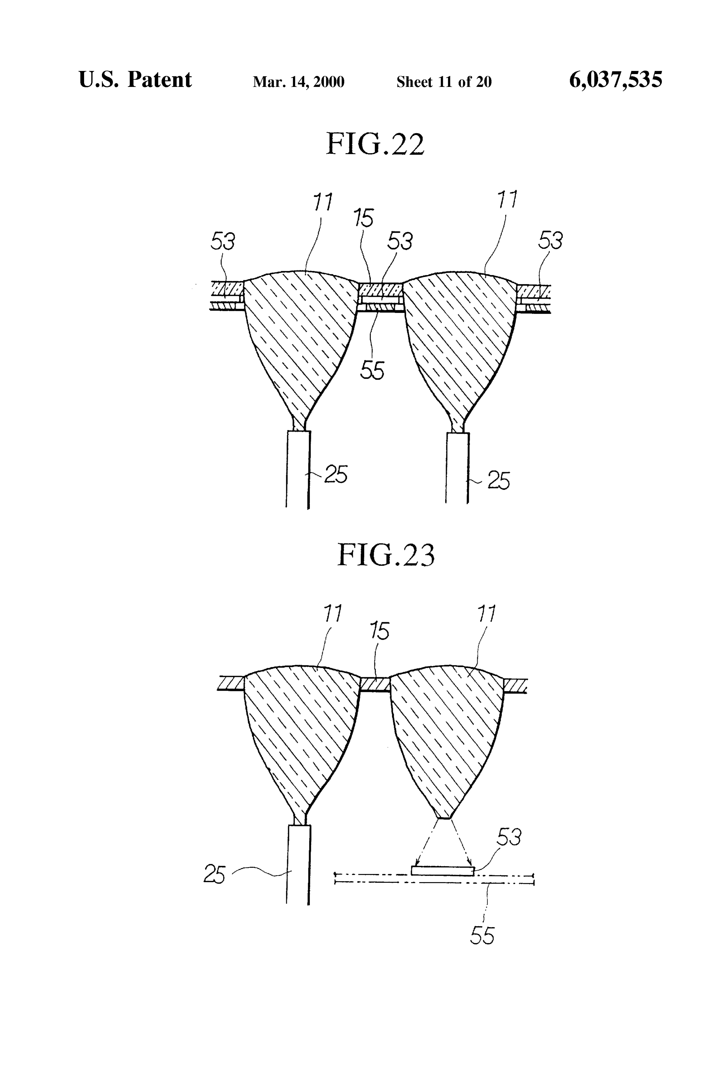
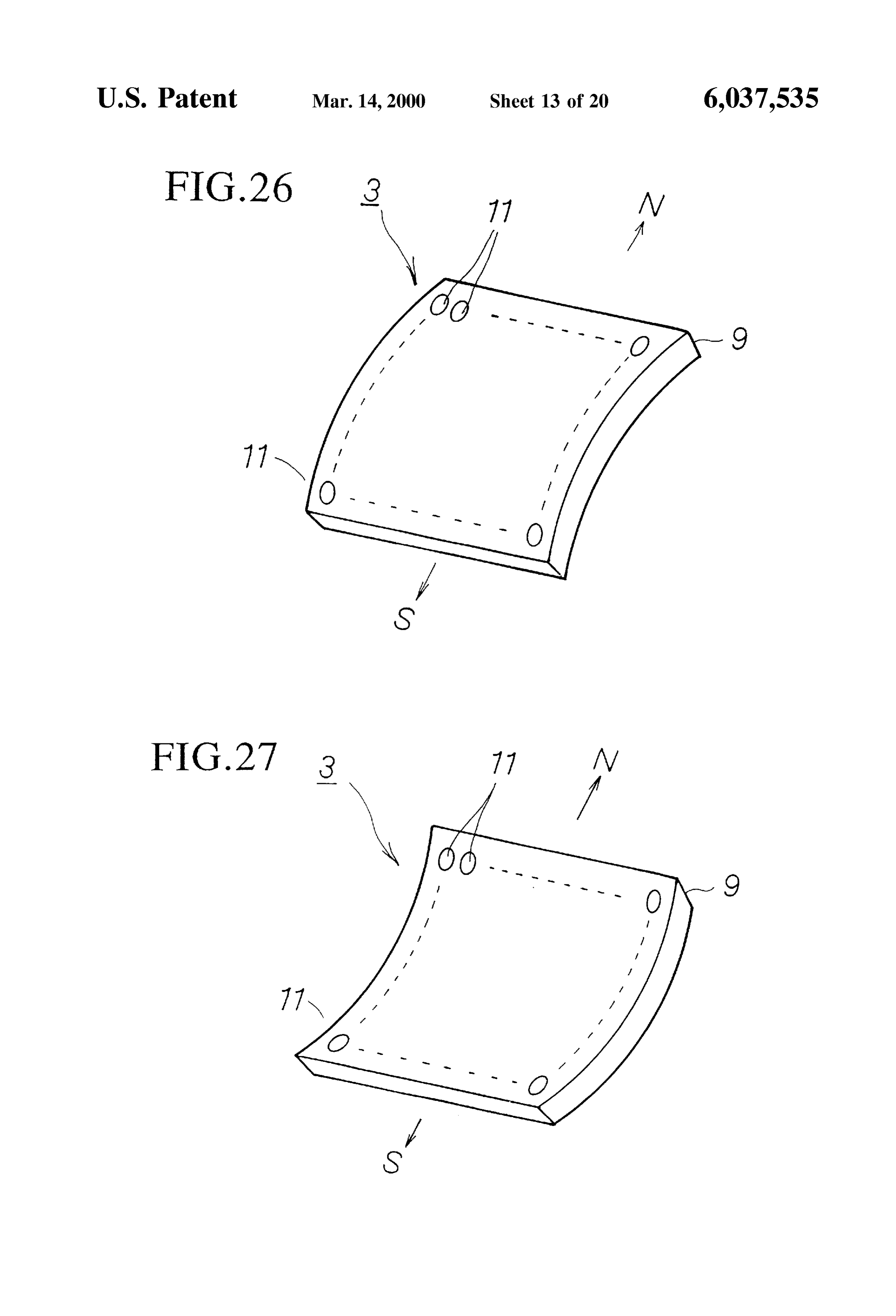
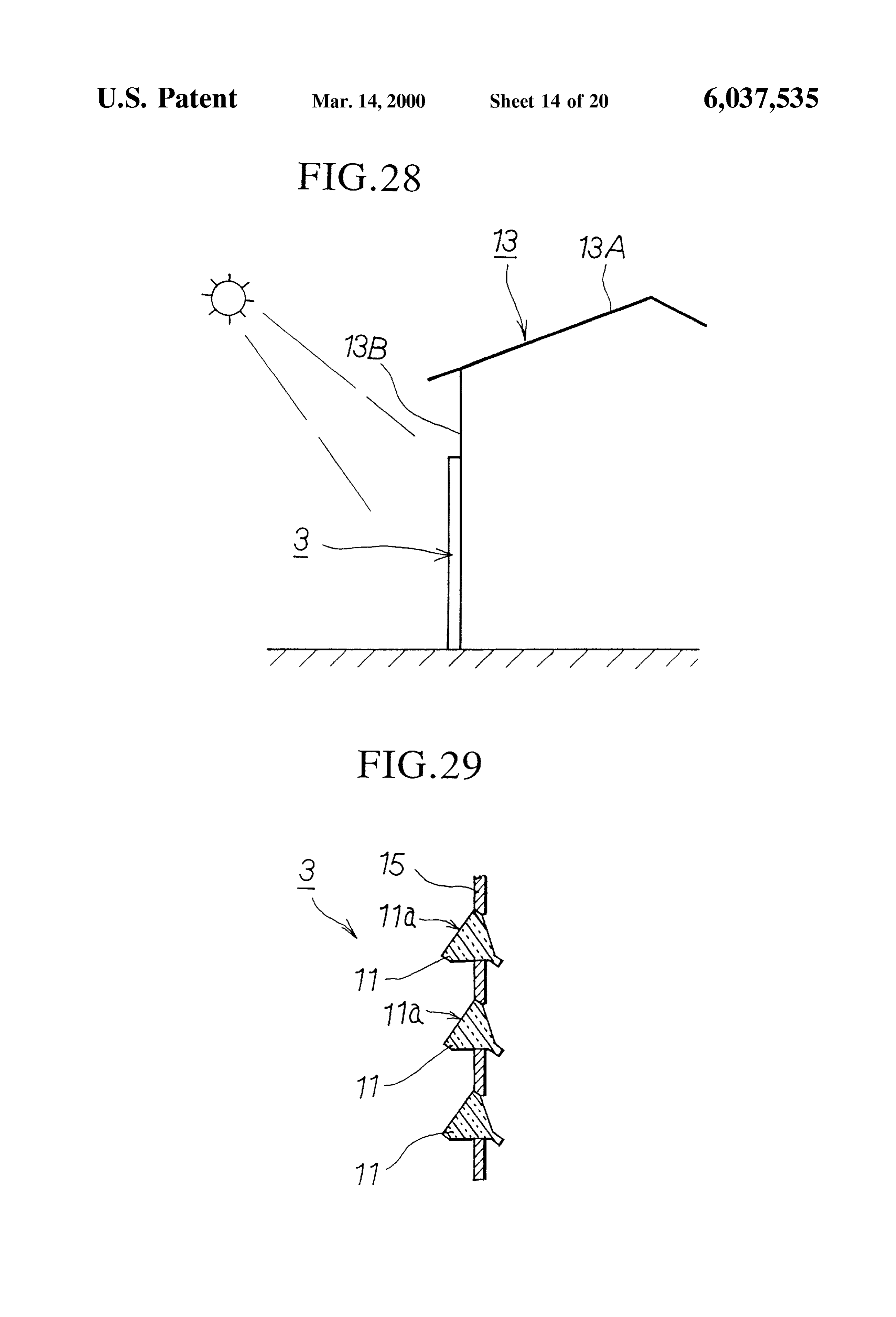
with the present embodiment, while Solar heat is received light gathering ability can be increased by using the follow while the lens elements are collecting Sunlight, the water ing structures. 1) While the plurality of lens elements 11 in route for tap water formed around the laterally arranged lens the case are arranged on the Same plane in the above elements allows the tap water inside the water route to embodiments, but depending upon the shape of the case 89, absorb the solar heat absorbed by the lens elements; thus, the the plurality of lens elements 11 can be arranged on a curved hot water Supply capabilities can be increased while Simul Surface which bulges outward in a lateral direction on the taneously preventing increases in the temperature of the lens case 89 as shown in FIG. 24, or the plurality of lens elements elements. Although the water route 41 was formed by 11 can be arranged on a curved Surface which is indented providing Separation panels 43 in the present embodiment, inwardly as shown in FIG. 25. In FIGS. 24 and 25, the the Structure is not necessarily restricted to Such, and the symbols N and S respectively indicate the directions north Same effects can be obtained by laying pipes back and forth and south when installing the light collection section 83. inside the case 9. Additionally, the plurality of lens elements 11 can be The fifth embodiment of the light collection section arranged on a curved Surface which bulges outwardly in a according to the present invention will be explained with vertical direction on the case 89 as shown in FIG. 26, the reference to the drawings. FIG.22 is a vertical section view 15 plurality of lens elements 11 can be arranged on a curved showing a light collection Section equipped with Solar cells surface which is indented inwardly as shown in FIG. 27, or according to the present embodiment. In the present they can be arranged on a curved Surface which bulges or embodiment, the Support panel (Support material) 15 of the indents in a vertical and lateral direction by combining the Sunlight collection apparatuS 1 is provided with Solar cells direction of curvature vertically and laterally. The rear 53. That is, in the present embodiment as shown in FIG. 22, portion of the lens element 11 can be supported by the a plurality of lens elements 11 are provided within the case Support panel 15 or the like when the lens elements are 9, the Support panel for Supporting these lens elements 11 is arranged on a curved Surface as mentioned above. formed from a transparent material, a plurality of Solar cells According to the Structural arrangement of the lens ele are installed in the Spaces between the lens elements 11 of ments 11 as explained above, if they are arranged on a the Support panel 15, and the Solar cells 53 are supported by 25 curved Surface which bulges or indents laterally, then as means of a separate Support panel (Support material) 55. much Sunlight as possible is able to be gathered even when Each of the plurality of Solar cells 53 is connected to a the angle of the Sun is low to the east or west directions. designated capacitor (not shown in the drawings) by means If they are arranged on a curved Surface which bulges or of electrical wiring, and these capacitors are connected to indents vertically, then as much Sunlight as possible is able electrical devices Such as light bulbs by way of designated to be gathered even when the angle of the Sun is low in electrical circuitry. As a result, the present-embodiment wintertime. By arranging the lens elements 11 on a cylin allows the lens elements to collect Sunlight in order to light drical Surface, the Sunlight gathering capability is able to be up the required rooms, while simultaneously charging the increased without a conventional tracking device, even if the Solar cells, thereby ensuring efficient use of Space oh the roof Sun in an eastern or western direction, or the Sun during of the building, which offers an advantage when a lot of 35 wintertime, is at a low angle.
Sunlight collection apparatuses are installed on the roof. 2) While the above embodiments explain cases wherein Next, the sixth embodiment of the light collection section the light collection Sections 3 are installed on the roof of a according to the present invention will be explained with building or hung from a pole, the Structure is not necessarily reference to the drawings. FIG. 23 is a vertical section view restricted to Such, and the light collection Sections 3 can be showing a light collection Section having Solar cells accord 40 attached to the side wall 13B of a well-lit building 13 as ing to the present embodiment. The present embodiment shown in FIG. 28, and may be built into the side wall 13B increases the electricity generation capability of the Solar during the construction of the building 13. In this case, the cells 53 by using the light gathering capabilities of the lens light collection capability of the lens elements 11" can be elements 11 of the Sunlight collection apparatuS 1. That is, increased by orienting the front Surfaces 11a" of the lens the present embodiment has a plurality of lens elements 11 45 elements 11 to face in a diagonal upward direction as shown Similar to those of the first and Second embodiments, except in FIG. 29.
that solar cells 53 are installed opposite the end surfaces of The seventh embodiment of the light collection section the connection portions 21 of Some of the lens elements, as according to the present invention will be explained with shown in FIG. 23. The plurality of Solar cells 53 are reference to the drawings. FIG. 30 is a side view showing a Supported by means of a Support panel 55. The lens elements 50 Seventh embodiment of a light collection Section according 11 may be Selected reciprocatively with the light-gathering to the present invention, showing a light collection Section lens elements 11. Each Solar cell 53 is connected to a wherein a plurality of lens elements are arranged in a dome designated capacitor (not shown in the drawings) by means shape. FIG. 31 is a plan view of a dome-shaped light of wiring which leads out of the case 9. In the present collection section. FIG. 32 is a side view showing a dome embodiment, the connection portion 21 of the lens element 55 shaped light collection Section installed on the rooftop of a 11 is removed, and the lens element 11 is formed so that building. FIG. 33 is a plan view showing a lens element Sunlight hits the entire Surface of a Solar cell having a having a hexagonal planar Shape. FIG. 34 is a Side view designated area. As a result, the present embodiment allows showing a lens element having a hexagonal planar shape. AS Solar electricity to be generated by Sunlight collected by the shown in FIGS.30 and 31, the light collection section 93 of lens elements which have exceptional light gathering 60 the present embodiment are formed in a dome shape with the capabilities, So that the electrical power generating ability of plurality of lens elements 911 arranged on a spherical the Solar cells increases and the electrical power is able to be Surface which bulges outwardly. The light collection Section reliably used in households. Combining the lens elements 93 may, for example, be installed on a well-lit roof 13A of with Solar cells allows the construction of a Solar cell a building 13 as shown in FIG. 32. As shown in FIGS. 33 apparatus with increased electrical power generating ability. 65 and 34, each lens element 911 is formed into a planar The lens elements are not necessarily restricted to the hexagonal shape, with flat contact surface portions 919b arrangements of the embodiments described above, and the which incline at a designated angle in a rearward direction
Page 28
formed on each side of the hexagon around the front portion Support panel 15. The shape of the arrangement of lens of the guide portion 919 of the lens element 911. The contact elements 911 is not necessarily restricted to a conical shape, surface portions 919b of the adjacent lens elements 911 and the plurality of lens elements 911 may be arranged So as contact these contact surface portions 919b so as to form a to form a polygonal pyramid shape. As a result, the present structure wherein the plurality of lens elements 911 are embodiment allows the same effects as the eighth embodi arranged in a spherical honeycomb. The inclination angles ment to be obtained.
of the contact surface portions 919b of the lens elements 911 The tenth embodiment of the light collection section are set such that the optical axis of each lens element 911 according to the present invention will be explained with passes through the center of the Spherical Surface; that is, the reference to the drawings. FIG. 38 is a section view along front Surface 911a of each lens element 11 is oriented in the the line 38-38 in FIG. 37 showing a light collection section radial direction. As shown in FIG. 30, the lens elements 911 having a Solar tracking device. FIG. 39 is an enlarged Section arranged on the Spherical Surface are Supported by means of View showing a rotary shaft and a shaft Support portion. FIG. a spherical Support panel 15 provided inside the plurality of 40 is an enlarged Section view showing a guide and a guide arranged lens elements. in the present embodiment, each roller. FIG. 41 is a section view along the line 41-41 in lens element 911 has a convex front Surface 911a, and 15 FIG. 38 showing a guide and a guide roller. FIG. 42 is a Fresnel rings 917 are formed on the front Surface 911a. section view along the line 42-42 in FIG. 38 showing a ring-shaped rack and a pinion provided on a motor. In the
Consequently, the present embodiment allows Sunlight to be collected by a plurality of lens elements facing in the radial present embodiment, a light collection Section 3 according direction, without having to track the Sun, when the dome to the first and second embodiments is further provided with a structure allowing the tracking of the Sun. That is, as shown shaped light collection Section is installed on a Southward in roof of a building. As a result, Sunlight is able to be reliably of FIGS.
37 and 38, a base 59 is installed on the roof 13A building 13, a light collection section 3 is rotatably gathered without being Significantly influenced by the height provided on this base 59, and the light collection section 3 of the Sun depending on the Seasons or the inclination angle is rotationally driven by means of a Solar tracking device 61. of the Sun during a Single day. As shown in FIG. 39, a rotary shaft 63 protrudes at a While the first, second and seventh embodiments have 25 designated angle of inclination from the approximate center been explained with Structures having the light collection of the bottom panel 9a of the case, and a shaft Support section 3 on the roof 13A, the light collection section 3 may portion 65 for supporting the rotary shaft 63 is attached at a be built into the roof 13A, or the entire roof 13A may be right angle to the top Surface of the base 59 at the approxi filled by the light collection section 3. mate center of the base 59. The angle of inclination of the The eighth embodiment of the light collection section rotary axis 63 protruding from the light collection Section 3 according to the present invention will be explained with is determined by the inclination of the roof 13 and the height reference to the drawings. FIG. 35 is a front view showing of the Sun. The bottom end portion of the rotary shaft 63 has a tree-shaped light collection Section having a plurality of a large diameter, this large diameter portion 63a is inserted dome-shaped light collection Sections arranged in a tree into the Shaft Support portion 65, and the large diameter fashion. As shown in FIG. 35, the light collection section 93 35 portion 63a is rotatably supported by a bearing 67 provided of the present embodiment uses dome-shaped light collec in the shaft Support portion 65. A lid portion 69 which tion sections 93 identical to those of the seventh engages with the top end Surface of the large diameter embodiment, and has a Structure which allows installation portion 63a is affixed to the top surface of the shaft Support not on the roof 13A of a building 13, but in any well-lit area portion 65 by means of bolts or the like, whereby the rotary such as a yard, as with the third embodiment. That is, the 40 shaft 63 is prevented from coming loose. present embodiment has a plurality of dome-shaped light As shown in FIGS. 37 and 38, a ring-shaped guide 71 is collection sections 93 having somewhat smaller diameters affixed to the top surface of the base 59. This guide 71 is than the light collection sections 93 of the seventh formed into a Semi-circle centered at the shaft Support embodiment, these dome-shaped light collection sections 93 portion 65, having a length which is Somewhat longer than being Supported on a pole (Support pole) So as to form a 45 180 in a circumferential direction centered on the shaft tree-shaped light collection section 93. The light collection support section 65, as shown in FIG. 41. A guide groove 73 Sections 93 become larger going from the upper portion to with an approximately C-shaped cross-section is formed in the lower portion of the pole 37, so as to collect as much the guide 71 as shown in FIG. 40. An engaging arm 75 which Sunlight as possible. Consequently, Sunlight is able to be intersects the base 59 protrudes from the bottom surface 9a reliably gathered without being Significantly influenced by 50 of the case of the light collection Section 3, and a guide roller the height of the Sun depending on the Seasons or the 77 is rotatably supported at the tip of the engaging arm 75. inclination angle of the Sun during a single day as with the The rotational axle 79 of the guide roller 77 is oriented so as Seventh embodiment, and the installation of the light col to orthogonally intersect the top surface of the base 59, and lection Section is made easier. is attached to the tip portion of the engaging arm 75 So as to The ninth embodiment of the light collection section 55 contact the guide surface 73a which is the front surface according to the present invention will be explained with inside the guide groove 73. As shown in FIG. 41, this reference to the drawings. FIG. 36 is a front view showing engaging arm 75 is provided at a lower central portion of the a tree-shaped light collection Section having a plurality of front Surface of the light collection portion 3, and may, for hexagonal lens elements arranged in a cone shape. The light example, have two guide rollers 77. When the light collec collection Section 3 of the present embodiment uses a 60 tion section 3 rotates while centered on the rotary shaft 63, plurality of lens elements with a hexagonal planar shape as the guide roller 77 moves along the guide surface 73a of the shown in FIGS. 33 and 34, with a structure arranged in a guide groove 73. The upper and lower Surfaces of the guide tree-fashion as shown in FIG. 36. That is, a plurality of lens groove 73 function as guides So that the top end and the elements 911 are arranged in a conical shape with a circum bottom end of the guide roller 77 do not come free from the ferential Surface which taperS in an upward direction on a 65 guide groove 73.
pole which is implanted in a yard or the like, the lens A semi-circular rack 82 is affixed to the bottom panel 9a elements being Supported from the inside by means of a of the case of the light collection section 3. This rack 81 is
Page 29
formed into-an approximate Semi-circle centered on the guiding Sunlight entering each lens element being inte rotary shaft 63, and has teeth 83 formed on the inner grally formed with Said lens element, Said guide portion circumference. As shown in FIG. 42, this rack 81 has a and Said lens element being Solid and unitarily formed, length somewhat longer than 180 in a circumferential the circumferential inner Surface of Said guide portion direction centered on the rotational axle 63, and is provided being a mirror Surface, and an optical fiber cable of Said with stopper portions 81a at both ends. On the other hand, light conducting portion being coupled to Said guide the top surface of the base 59 is affixed with a motor 87 portion.
attached with a pinion which engages the rack 81. The 2. A Sunlight collection apparatus according to claim 1, rotational axle of the motor 87 is affixed to the base 59 So as wherein the front Surface of each of Said lens elements is
COWCX.
to orthogonally intersect the bottom panel 9a of the case of 3. A Sunlight collection apparatus according to claim 1, the light collection section 3, a pinion 85 is affixed to this wherein the front Surface of each of Said lens elements is rotational axle, and the motor 87 is connected to a control COCVC.
Section (not shown in the drawings). The structure is Such as 4. A Sunlight collection apparatus according to claim 1, to allow the light collection section 3 to rotate about the wherein the front Surface of each of Said lens elements is in rotary shaft 63 by rotating the motor 87 based on controls 15 the shape of a spherical Section.
from the control Section. In this case, the light collection 5. A Sunlight collection apparatus according to claim 1, Section 3 is able to be rotated Smoothly because the guide wherein the front Surface of each of Said lens elements is in rollers 77 are guided by the guide groove 73. An optical the shape of a cylindrical Surface Section. sensor 89 is provided at the approximate center of the light 6. A Sunlight collection apparatus according to claim 1, collection section 3, and this optical sensor 89 is connected wherein the front Surface of each of said lens elements forms to the control Section. The approximate position of the Sun a Fresnel lens provided with Fresnel rings. is detected by means of the optical sensor 89, and the control 7. A Sunlight collection apparatus according to claim 1, Section controls the rotational drive of the motor 87 based on wherein a circumferential Surface of Said guide portion is the detection signals from the optical sensor 89. Therefore, COWCX.
the light collection Section 3 is rotated in correspondence 25 8. A Sunlight collection apparatus according to claim 1, with the movement of the Sun over a single day, So that the wherein a plurality of polygonal conveX Surfaces are formed light collection section 3 is able to collect light while on the front Surface of each of Said lens elements, and tracking the Sun. A timer is provided in the control Section, Fresnel rings are provided on each of Said conveX Surfaces. so that when the time is 6:00 PM, for example, the motor 87 9. A Sunlight collection apparatus according to claim 1, is rotated in reverse So as to move the light collection Section wherein a horizontal cross-section of each of Said lens 3 from a westward-facing orientation through the Southside elements is circular.
to lock onto an eastward-facing orientation in order to reset 10. A Sunlight collection apparatus according to claim 1, the apparatus for the following day. The tracking device 61 wherein a horizontal croSS-Section of each of Said lens comprises a rotary Shaft 63, a shaft Support Section 65, a elements is polygonal.
guide 71, an engaging arm 75, a guide roller 77, a rack 81, 35 11. A Sunlight collection apparatus according to claim 1, a motor 87, a pinion 85, an optical sensor 89, a timer and a wherein a horizontal cross-section of each of Said lens control Section. elements is hexagonal.
Consequently, the present embodiment allows the light 12. A Sunlight collection apparatus according to claim 1, gathering capability to be increased in comparison to the wherein Said plurality of lens elements are arranged on a light collection Section which gathers light while affixed to 40 curved surface which is curved with respect to the horizontal the roof, Since the light collection Section is always oriented plane.
in the direction of the Sun. When tracking the Sun, Sunlight 13. A Sunlight collection apparatus according to claim 1, is able to be reliably gathered even if the Sun is not aligned wherein Said plurality of lens elements is arranged in hous with the optical axis of the lens elements, So that light is able ings to form a plurality of light collection portions, Said light to be reliably gathered even with rough Solar tracking, 45 collection portions being arranged in a tree-form by being thereby allowing the tracking device to be made Simpler and detachably hung on a Support, the tree-form having Said lens making the apparatus as a whole cheaper. elements shaped in a form of leaves of a tree provided on While the above-mentioned embodiments were primarily Said14.Support. A Sunlight collection apparatus according to claim 1, explained in cases wherein the apparatus is used in a 50 wherein Said plurality of lens elements are arranged on a residential building, they are not necessarily restricted to conical Surface which tapers toward the upper portion Such and may be applied to other buildings, Such as office thereof.
buildings, or may be applied to plant cultivation. 15. A Sunlight collection apparatus according to claim 1, I claim:
1. A Sunlight collection apparatus, comprising: wherein Said plurality of lens elements are arranged on a 55 convex spherical Section Surface So that Said light collection a light collection portion for collecting Sunlight; portion is in the shape of a dome. a light conducting portion comprising optical fiber cables 16. A Sunlight collection apparatus according to claim 15, for conducting Sunlight collected by Said light collec wherein a plurality of Said light collection portions are tion portion, and Supported by an implanted Support pole. a light Scattering portion provided at an end of Said light 60 17. A Sunlight collection apparatus according to claim 1, conducting portion, for emitting Sunlight conducted by wherein Said lens elements are arranged inside a housing Said light conducting portion; being provided with a water path for running water from a wherein Said light collection portion comprises a plurality bottom row of lens elements to a top row of lens elements, of lens elements, a front Surface of each lens element and being connected to a cold water pipe for introducing being curved, each lens element having an approxi 65 water to Said water path at Said bottom row and a hot water mately conical portion being tapered from Said front pipe for allowing hot water to flow from Said water path at Surface toward a rearward direction, a guide portion for Said top row.
Page 30
18. A Sunlight collection apparatus according to claim 17, a light Scatterer, provided at an end of Said light conduc wherein Said water path is formed around Said lens elements tor, in order to allow water to absorb Solar heat.
19. A Sunlight collection apparatus according to claim 1, wherein Said light collector comprises a plurality of lens wherein Said light collection portion, having Said plurality of 5 elements, each lens element being tapered from a front lens elements arranged flatly or on a curved Surface, is Surface toward a rearward direction, a conical guide provided with a tracking device which rotates Said light portion for guiding Sunlight entering each lens element collection portion in order to follow the path of the Sun. being integrally formed with Said lens element, Said 20. A Sunlight collection apparatus according to claim 1, guide portion being unitarily formed of transparent wherein a diameter of a rear end of Said guide portion is 10 material, a circumferential inner Surface of Said guide equal to a diameter of Said optical fiber cable. portion being a mirror Surface, and an optical fiber 21. A Sunlight collection apparatus, comprising: cable of Said light conductor being coupled to Said a light collector for collecting Sunlight; guide portion.
a light conductor, comprising optical fibers, for conduct ing Sunlight collected by Said light collector, and k . . . .

Provenance
- Collection
- Cited prior art
- Original PDF
- patentimages.storage.googleapis.com →
- Filed
- 1996-07-16
- Pages
- 30
- Method
- pdftotext (the PDF's own text layer) + pdftoppm 300dpi page scans
- Source
- Google Patents bibliographic record
- Granted
- 2000-03-14
- Inventors
- Kazuo Yoshino
- Transcribed from
- patentimages.storage.googleapis.com →