patent · US5501743
Fiber optic power-generating system
26 March 1996
Page 1 — bibliographic record
United States Patent (19) 11 Patent Number: 5,501,743 Cherney 45 Date of Patent: Mar. 26, 1996 54 FIBER OPTIC POWER-GENERATING 4,236,937 12/1980 Wihl ........................................ 136/246 SYSTEM 4,529,830 7/1985 Daniel ... ... 136/246 5,089,055 2/1992 Nakamura ............................... 136/248 (76 Inventor Mathy Chryslerk La., FOREIGN PATENT DOCUMENTS 61-231773 10/1986 Japan ..................................... 136/246 (21) Appl. No.: 289.285 2-158500 6/1990 Japan ..................................... 136/246 22 Filed: Aug. 11, 1994 Primary Examiner Aaron Weisstuch (51) Int. Cl. ....................... H01L 31/052; HOL 31/058; Attorney, Agent, or Firm-Herbert Dubno
52 U.S. Cl. .......................... 2. Eg: A fiber optical solar power generating system provides a y tower outside a structure to be supplied with solar energy 58 Field of Search ..................................... 136/246, 248; and on which a multiplicity of collectors are provided. An 126/684, 698-699, 663, 675, 683, 700 optical fiber trunk carries the collected optical energy to the 56 Ref Cited structure in which a photovoltaic and/or a light/heat trans 56) eferences Ute ducing stack can be provided and to which light is distrib
not occupy large areas of the property.
3,780,722 12/1973 Swet ........................................ 126/688 4,080,221 3/1978 Manelas . ... 136/248 4,117,682 10/1978 Smith ..................................... 60/641.8 11 Claims, 3 Drawing Sheets
STRUCTURE T. SPACE HEATING
LIGHT (HEAT
STACK
Page 2
Drawing sheet — no readable text.
Page 3
Drawing sheet — no readable text.
Page 4
Drawing sheet — no readable text.
Page 5
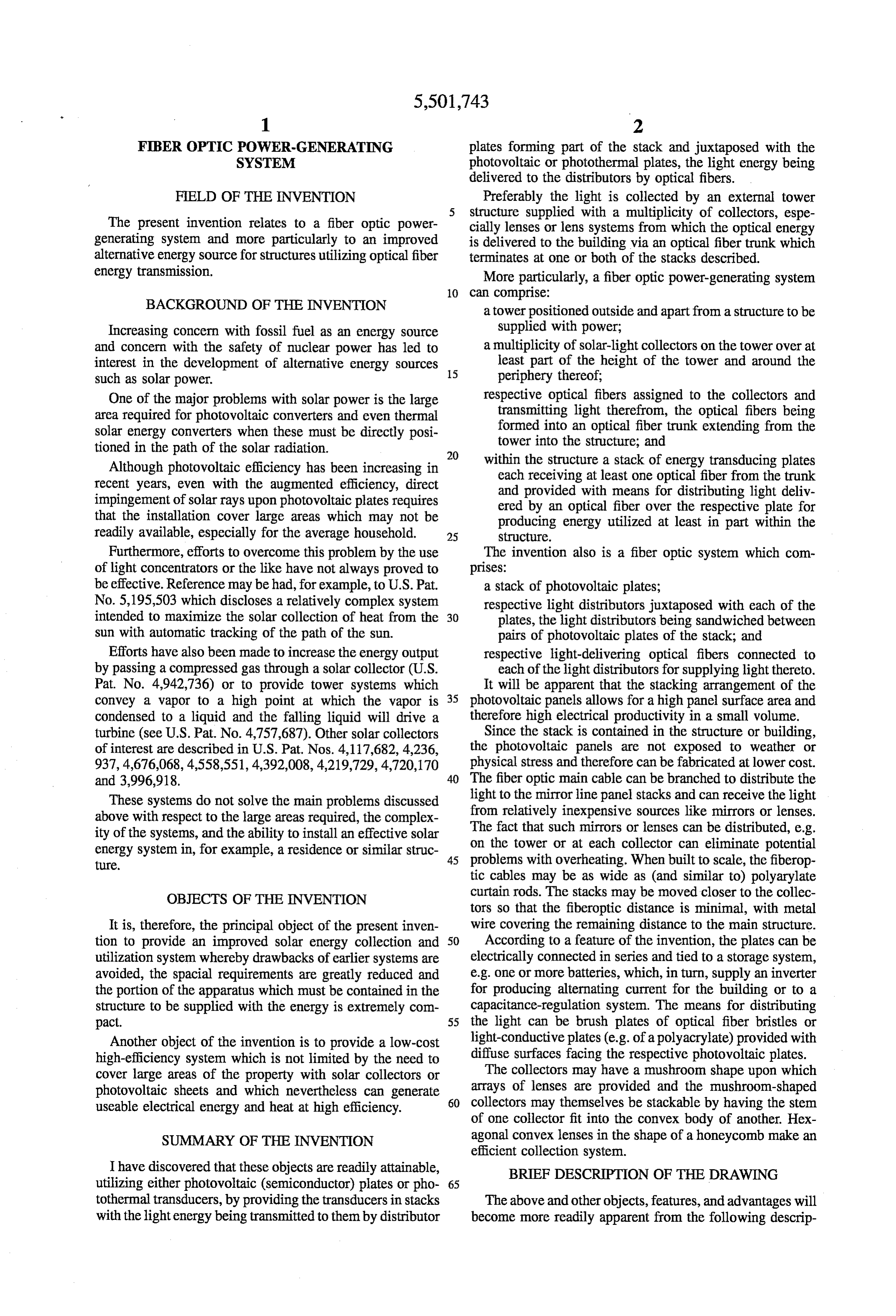
FBER OPTIC POWER-GENERATING plates forming part of the stack and juxtaposed with the SYSTEM photovoltaic or photothermal plates, the light energy being delivered to the distributors by optical fibers.
FIELD OF THE INVENTION Preferably the light is collected by an external tower 5 structure supplied with a multiplicity of collectors, espe
The present invention relates to a fiber optic power cially lenses or lens systems from which the optical energy generating system and more particularly to an improved is delivered to the building via an optical fiber trunk which alternative energy source for structures utilizing optical fiber terminates at one or both of the stacks described. energy transmission. More particularly, a fiber optic power-generating system 10 can comprise:
BACKGROUND OF THE INVENTION a tower positioned outside and apart from a structure to be Increasing concern with fossil fuel as an energy source supplied with power;
and concern with the safety of nuclear power has led to a multiplicity of solar-light collectors on the tower over at interest in the development of alternative energy sources 15 least part of the height of the tower and around the such as solar power. periphery thereof;
One of the major problems with solar power is the large respective optical fibers assigned to the collectors and area required for photovoltaic converters and even thermal transmitting light therefrom, the optical fibers being solar energy converters when these must be directly posi formed into an optical fiber trunk extending from the tioned in the path of the solar radiation. tower into the structure, and 20 within the structure a stack of energy transducing plates
Although photovoltaic efficiency has been increasing in each receiving at least one optical fiber from the trunk recent years, even with the augmented efficiency, direct and provided with means for distributing light deliv impingement of solar rays upon photovoltaic plates requires ered by an optical fiber over the respective plate for that the installation cover large areas which may not be producing energy utilized at least in part within the readily available, especially for the average household. 25 Structure.
Furthermore, efforts to overcome this problem by the use The invention also is a fiber optic system which com of light concentrators or the like have not always proved to prises:
be effective. Reference may be had, for example, to U.S. Pat. a stack of photovoltaic plates; No. 5,195,503 which discloses a relatively complex system respective light distributors juxtaposed with each of the intended to maximize the solar collection of heat from the 30 plates, the light distributors being sandwiched between sun with automatic tracking of the path of the sun. pairs of photovoltaic plates of the stack; and Efforts have also been made to increase the energy output respective light-delivering optical fibers connected to by passing a compressed gas through a solar collector (U.S. each of the light distributors for supplying light thereto. Pat. No. 4,942,736) or to provide tower systems which It will be apparent that the stacking arrangement of the convey a vapor to a high point at which the vapor is 35 photovoltaic panels allows for a high panel surface area and condensed to a liquid and the falling liquid will drive a therefore high electrical productivity in a small volume. turbine (see U.S. Pat. No. 4,757,687). Other solar collectors Since the stack is contained in the structure or building, of interest are described in U.S. Pat. Nos. 4,117,682, 4,236, the photovoltaic panels are not exposed to weather or 937, 4,676,068, 4,558,551, 4,392,008, 4,219,729, 4,720,170 physical stress and therefore can be fabricated at lower cost. and 3,996,918. 40 The fiber optic main cable can be branched to distribute the These systems do not solve the main problems discussed light to the mirror line panel stacks and can receive the light above with respect to the large areas required, the complex from relatively inexpensive sources like mirrors or lenses. ity of the systems, and the ability to install an effective solar The fact that such mirrors or lenses can be distributed, e.g. on the tower or at each collector can eliminate potential energy system in, for example, a residence or similar struc 45 problems ture. with overheating. When built to scale, the fiberop tic cables may be as wide as (and similar to) polyarylate
OBJECTS OF THE INVENTION curtain rods. The stacks may be moved closer to the collec tors so that the fiberoptic distance is minimal, with metal
It is, therefore, the principal object of the present inven wire covering the remaining distance to the main structure. tion to provide an improved solar energy collection and 50 According to a feature of the invention, the plates can be utilization system whereby drawbacks of earlier systems are electrically connected in series and tied to a storage system, avoided, the spacial requirements are greatly reduced and e.g. one or more batteries, which, in turn, supply an inverter the portion of the apparatus which must be contained in the for producing alternating current for the building or to a structure to be supplied with the energy is extremely com capacitance-regulation system. The means for distributing pact. 55 the light can be brush plates of optical fiber bristles or Another object of the invention is to provide a low-cost light-conductive plates (e.g. of a polyacrylate) provided with diffuse surfaces facing the respective photovoltaic plates.
high-efficiency system which is not limited by the need to cover large areas of the property with solar collectors or The collectors may have a mushroom shape upon which photovoltaic sheets and which nevertheless can generate 60 arrays of lenses are provided and the mushroom-shaped useable electrical energy and heat at high efficiency. collectors may themselves be stackable by having the stem of one collector fit into the convex body of another. Hex
SUMMARY OF THE INVENTION agonal convex lenses in the shape of a honeycomb make an efficient collection system.
I have discovered that these objects are readily attainable, BRIEF DESCRIPTION OF THE DRAWING utilizing either photovoltaic (semiconductor) plates or pho 65 tothermal transducers, by providing the transducers in stacks The above and other objects, features, and advantages will with the lightenergy being transmitted to them by distributor become more readily apparent from the following descrip
Page 6
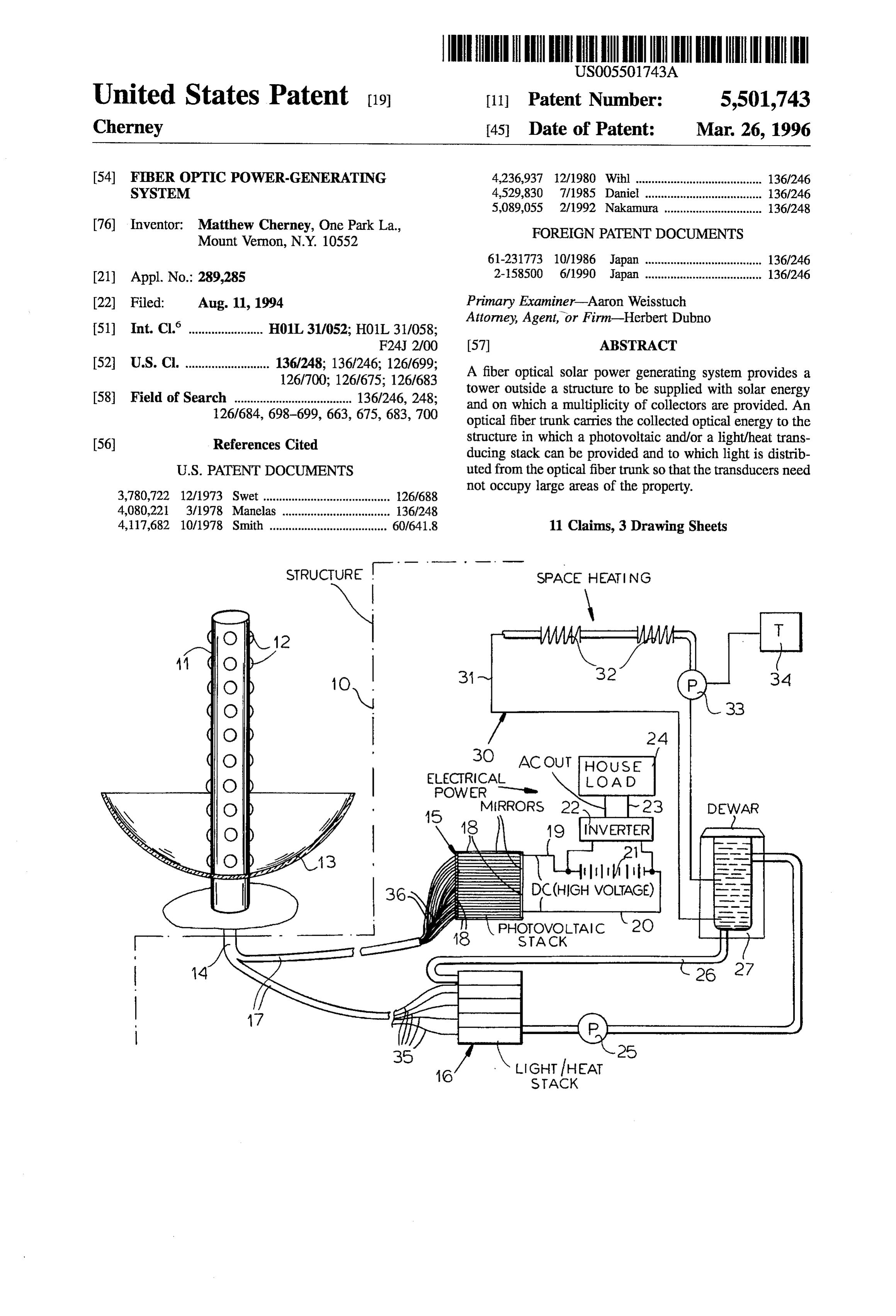
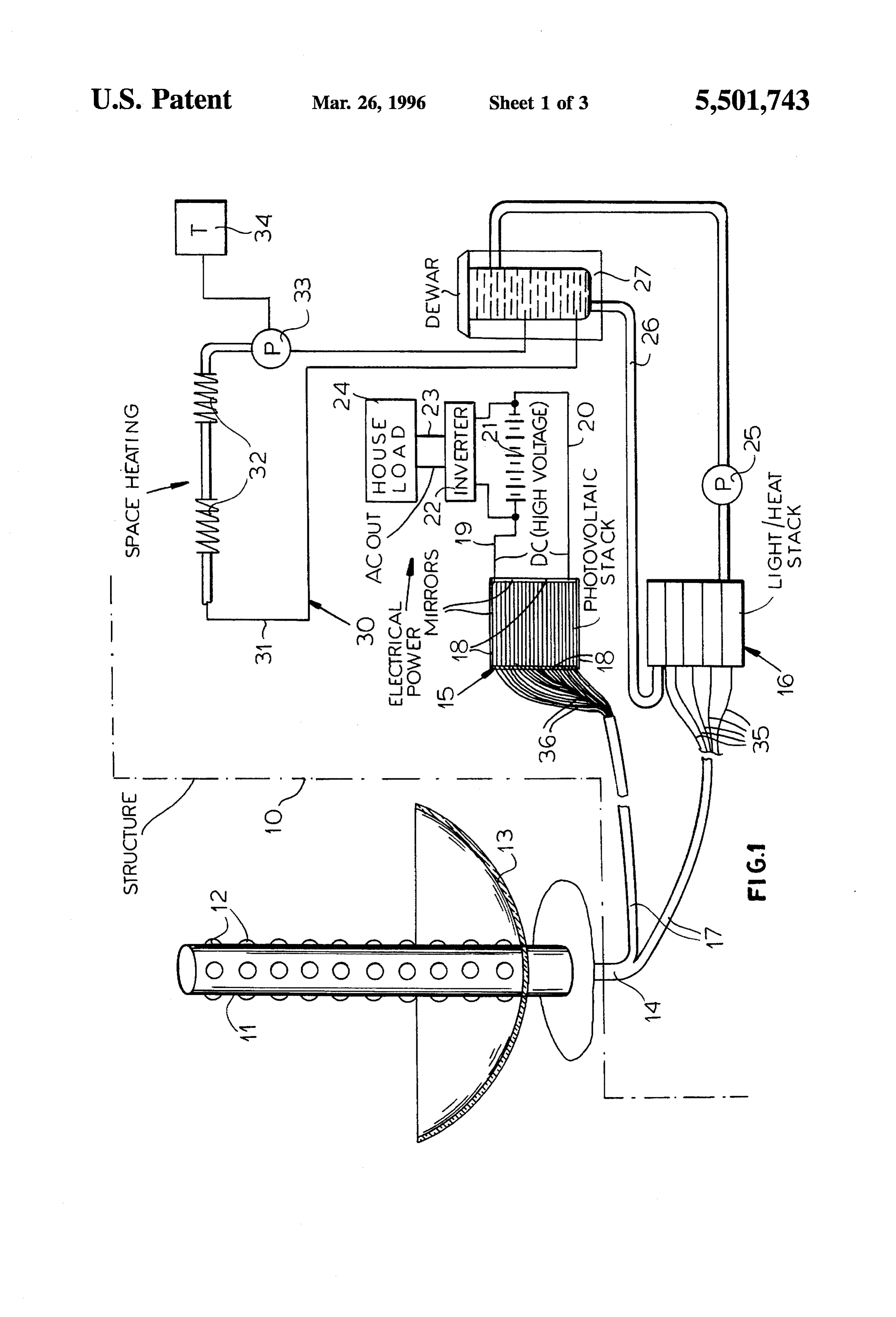
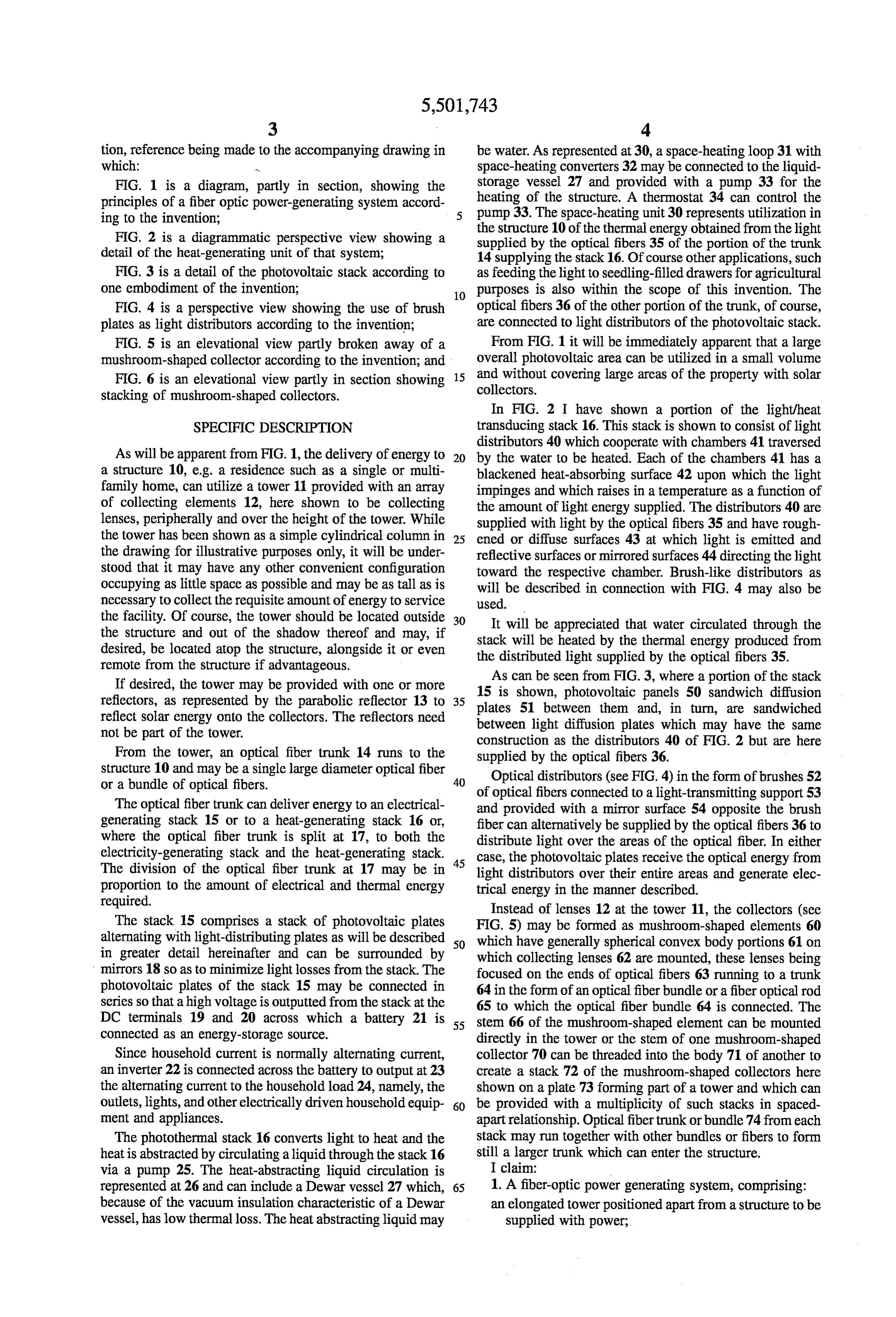
tion, reference being made to the accompanying drawing in be water. As represented at 30, a space-heating loop 31 with which: - space-heating converters 32 may be connected to the liquid FIG. 1 is a diagram, partly in section, showing the storage vessel 27 and provided with a pump 33 for the principles of a fiber optic power-generating system accord heating of the structure. A thermostat 34 can control the ing to the invention; pump 33. The space-heating unit 30 represents utilization in FIG. 2 is a diagrammatic perspective view showing a the structure 10 of the thermal energy obtained from the light detail of the heat-generating unit of that system; supplied by the optical fibers 35 of the portion of the trunk 14 supplying the stack 16. Of course other applications, such
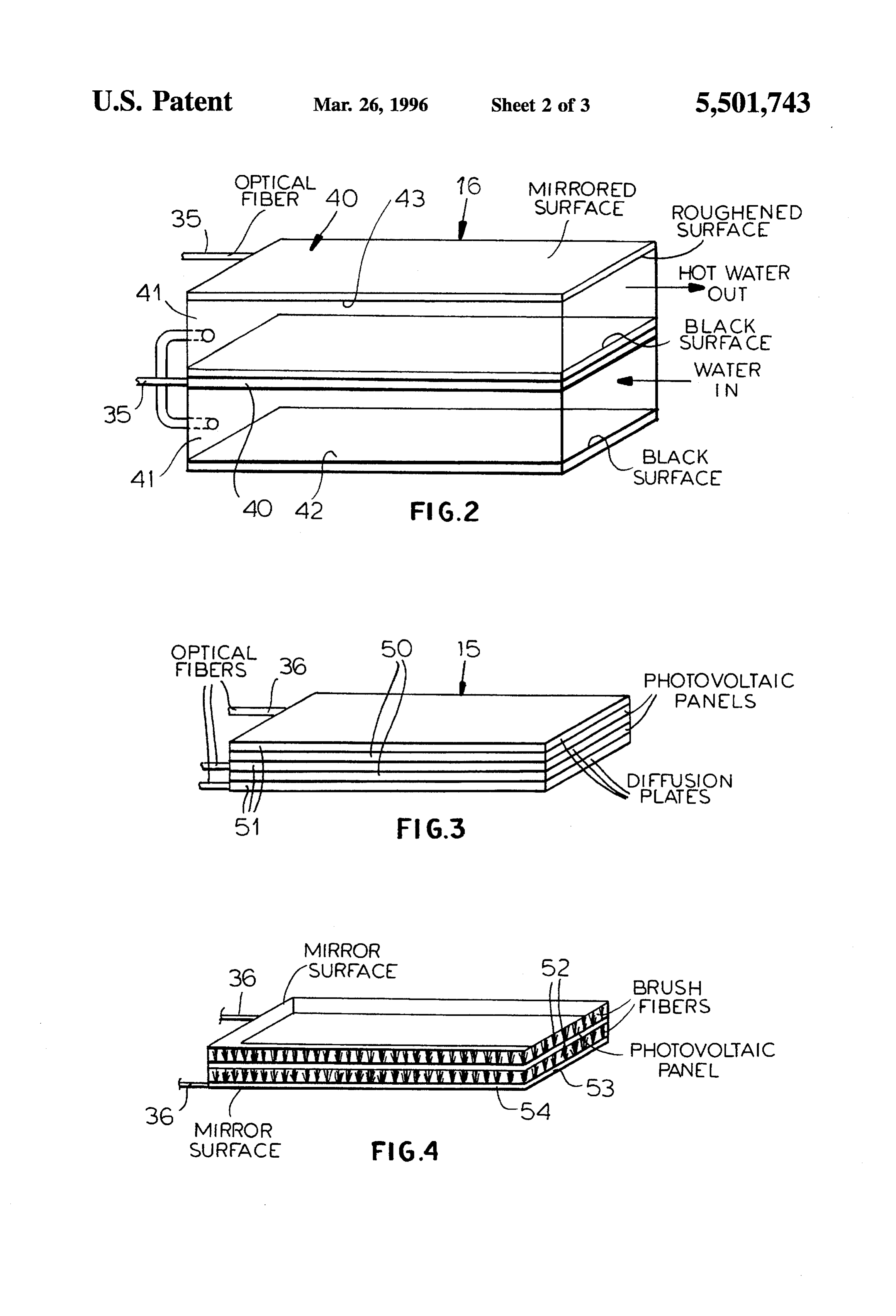
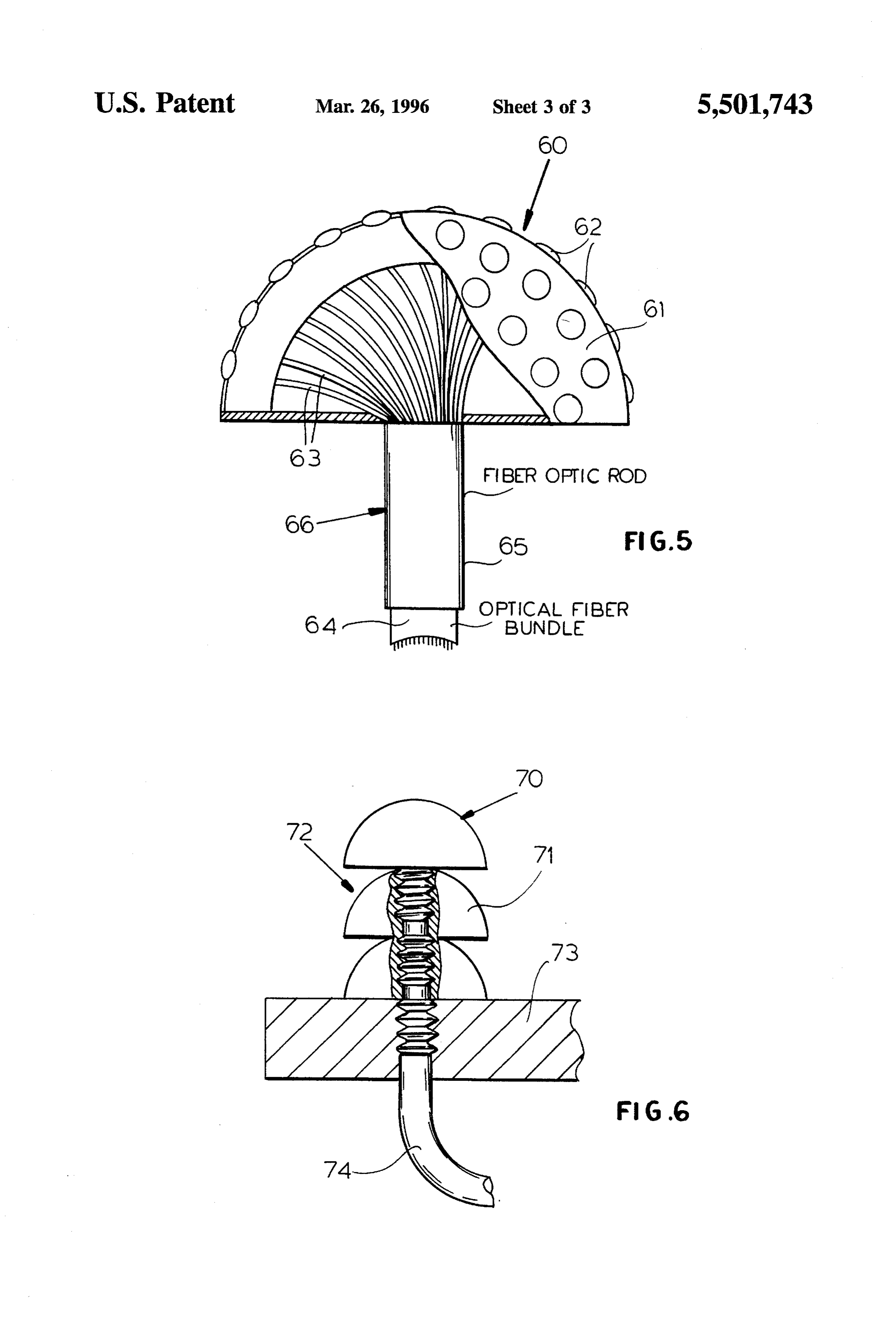
FIG. 3 is a detail of the photovoltaic stack according to as feeding the light to seedling-filled drawers for agricultural one embodiment of the invention; 10 purposes is also within the scope of this invention. The FIG. 4 is a perspective view showing the use of brush optical fibers 36 of the other portion of the trunk, of course, plates as light distributors according to the invention; are connected to light distributors of the photovoltaic stack. FIG. 5 is an elevational view partly broken away of a From FIG. 1 it will be immediately apparent that a large mushroom-shaped collector according to the invention; and overall photovoltaic area can be utilized in a small volume and without covering large areas of the property with solar
FIG. 6 is an elevational view partly in section showing 15 collectors.
stacking of mushroom-shaped collectors.
In FIG. 2 I have shown a portion of the light/heat
SPECIFC DESCRIPTION transducing stack 16. This stack is shown to consist of light distributors 40 which cooperate with chambers 41 traversed
As will be apparent from FIG. 1, the delivery of energy to 20 by the water to be heated. Each of the chambers 41 has a a structure 10, e.g. a residence such as a single or multi blackened heat-absorbing surface 42 upon which the light family home, can utilize a tower 11 provided with an array impinges and which raises in a temperature as a function of of collecting elements 12, here shown to be collecting the amount of light energy supplied. The distributors 40 are lenses, peripherally and over the height of the tower. While supplied with light by the optical fibers 35 and have rough the tower has been shown as a simple cylindrical column in 25 ened or diffuse surfaces 43 at which light is emitted and the drawing for illustrative purposes only, it will be under reflective surfaces or mirrored surfaces 44 directing the light stood that it may have any other convenient configuration toward the respective chamber. Brush-like distributors as occupying as little space as possible and may be as tall as is will be described in connection with FIG. 4 may also be necessary to collect the requisite amount of energy to service used.
the facility. Of course, the tower should be located outside 30 It will be appreciated that water circulated through the the structure and out of the shadow thereof and may, if stack will be heated by the thermal energy produced from desired, be located atop the structure, alongside it or even the distributed light supplied by the optical fibers 35. remote from the structure if advantageous.
If desired, the tower may be provided with one or more As can be seen from FIG.3, where a portion of the stack 15 is shown, photovoltaic panels 50 sandwich diffusion reflectors, as represented by the parabolic reflector 13 to 35 plates reflect solar energy onto the collectors. The reflectors need 51 between them and, in turn, are sandwiched not be part of the tower. between light diffusion plates which may have the same construction as the distributors 40 of FIG. 2 but are here
From the tower, an optical fiber trunk 14 runs to the supplied by the optical fibers 36.
structure 10 and may be a single large diameter optical fiber Optical distributors (see FIG. 4) in the form of brushes 52 or a bundle of optical fibers. 40 of optical fibers connected to a light-transmitting support 53
The optical fiber trunk can deliver energy to an electrical and provided with a mirror surface 54 opposite the brush generating stack 15 or to a heat-generating stack 16 or, fiber can alternatively be supplied by the optical fibers 36 to where the optical fiber trunk is split at 17, to both the distribute light over the areas of the optical fiber. In either electricity-generating stack and the heat-generating stack. 45 case, the photovoltaic plates receive the optical energy from The division of the optical fiber trunk at 17 may be in light distributors over their entire areas and generate elec proportion to the amount of electrical and thermal energy trical energy in the manner described. required.
Instead of lenses 12 at the tower 11, the collectors (see
The stack 15 comprises a stack of photovoltaic plates FIG. 5) may be formed as mushroom-shaped elements 60 alternating with light-distributing plates as will be described 50 which have generally spherical convex body portions 61 on in greater detail hereinafter and can be surrounded by which collecting lenses 62 are mounted, these lenses being mirrors 18 so as to minimize light losses from the stack. The focused on the ends of optical fibers 63 running to a trunk photovoltaic plates of the stack 15 may be connected in 64 in the form of an optical fiberbundle or a fiber optical rod series so that a high voltage is outputted from the stack at the 65 to which the optical fiber bundle 64 is connected. The DC terminals 19 and 20 across which a battery 21 is 55 stem 66 of the mushroom-shaped element can be mounted connected as an energy-storage source. directly in the tower or the stem of one mushroom-shaped Since household current is normally alternating current, collector 70 can be threaded into the body 71 of another to an inverter 22 is connected across the battery to output at 23 create a stack 72 of the mushroom-shaped collectors here the alternating current to the household load 24, namely, the shown on a plate 73 forming part of a tower and which can outlets, lights, and other electrically driven household equip 60 be provided with a multiplicity of such stacks in spaced ment and appliances. apart relationship. Optical fibertrunk or bundle 74 from each The photothermal stack 16 converts light to heat and the stack may run together with other bundles or fibers to form heatis abstracted by circulating a liquid through the stack 16 still a larger trunk which can enter the structure. via a pump 25. The heat-abstracting liquid circulation is I claim:
represented at 26 and can include a Dewar vessel 27 which, 65 1. A fiber-optic power generating system, comprising: because of the vacuum insulation characteristic of a Dewar an elongated tower positioned apart from a structure to be vessel, has low thermal loss. The heat abstracting liquid may supplied with power;
Page 7
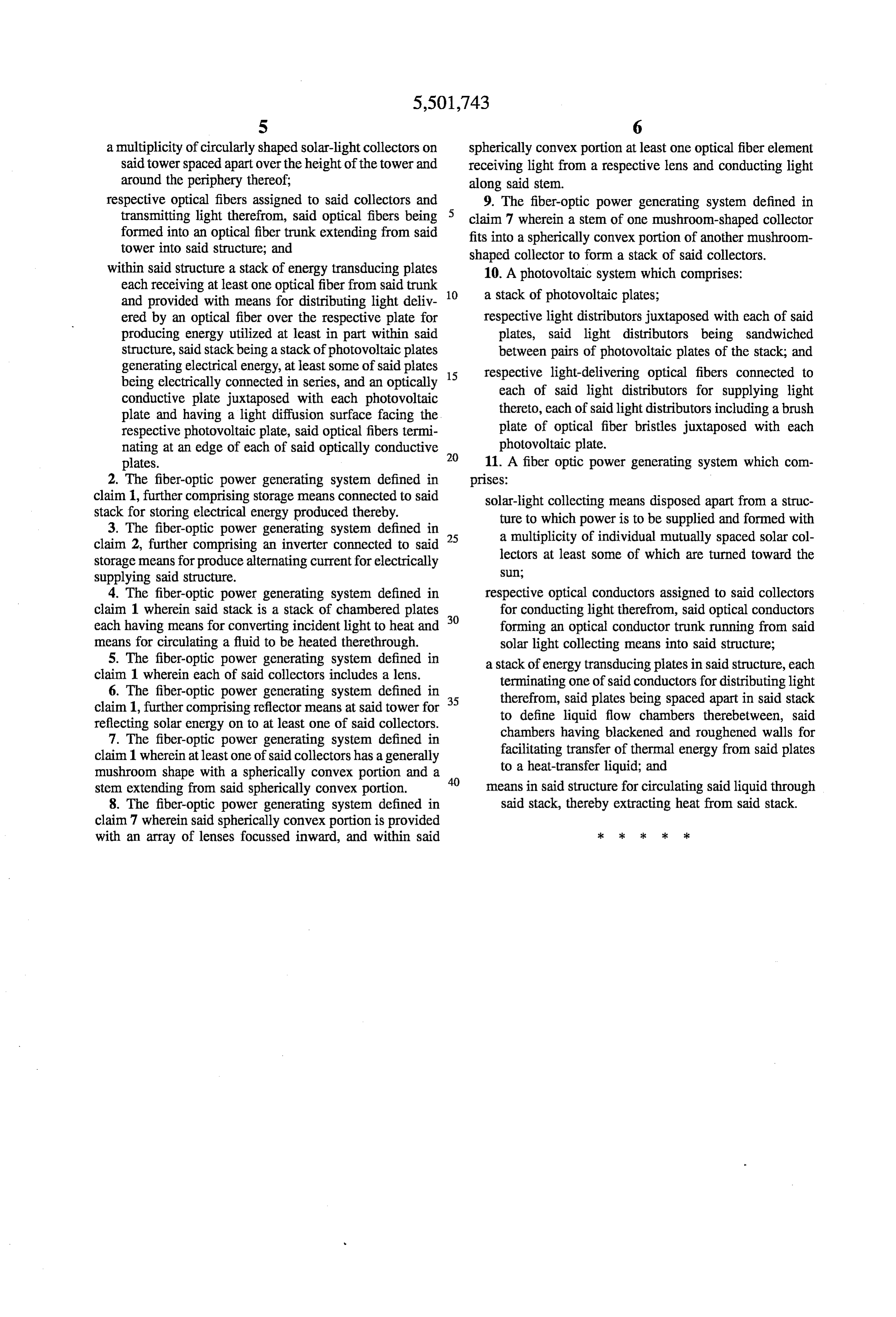
S 6 a multiplicity of circularly shaped solar-light collectors on spherically convex portion at least one optical fiber element said tower spaced apart over the height of the tower and receiving light from a respective lens and conducting light around the periphery thereof; along said stem.
respective optical fibers assigned to said collectors and 9. The fiber-optic power generating system defined in transmitting light therefrom, said optical fibers being claim 7 wherein a stem of one mushroom-shaped collector formed into an optical fiber trunk extending from said fits into a spherically convex portion of another mushroom tower into said structure, and shaped collector to form a stack of said collectors. within said structure a stack of energy transducing plates 10. A photovoltaic system which comprises: each receiving at least one optical fiber from said trunk 10 a stack of photovoltaic plates; and provided with means for distributing light deliv ered by an optical fiber over the respective plate for respective light distributors juxtaposed with each of said producing energy utilized at least in part within said plates, said light distributors being sandwiched structure, said stack being a stack of photovoltaic plates between pairs of photovoltaic plates of the stack; and generating electrical energy, at least some of said plates respective light-delivering optical fibers connected to being electrically connected in series, and an optically 15 each of said light distributors for supplying light conductive plate juxtaposed with each photovoltaic plate and having a light diffusion surface facing the thereto, each of said light distributors including a brush respective photovoltaic plate, said optical fibers termi plate of optical fiber bristles juxtaposed with each nating at an edge of each of said optically conductive 20 photovoltaic plate.
plates. 11. A fiber optic power generating system which com 2. The fiber-optic power generating system defined in prises:
claim 1, further comprising storage means connected to said solar-light collecting means disposed apart from a struc stack for storing electrical energy produced thereby. ture to which power is to be supplied and formed with 3. The fiber-optic power generating system defined in 25 a multiplicity of individual mutually spaced solar col claim 2, further comprising an inverter connected to said lectors at least some of which are turned toward the storage means for produce alternating current for electrically supplying said structure. Sll, 4. The fiber-optic power generating system defined in respective optical conductors assigned to said collectors claim 1 wherein said stack is a stack of chambered plates 30 for conducting light therefrom, said optical conductors each having means for converting incident light to heat and forming an optical conductor trunk running from said means for circulating a fluid to be heated therethrough. solar light collecting means into said structure; 5. The fiber-optic power generating system defined in a stack of energy transducing plates in said structure, each claim 1 wherein each of said collectors includes a lens. terminating one of said conductors for distributing light 6. The fiber-optic power generating system defined in 35 therefrom, said plates being spaced apart in said stack claim 1, further comprising reflector means at said tower for to define liquid flow chambers therebetween, said reflecting solar energy on to at least one of said collectors. chambers having blackened and roughened walls for 7. The fiber-optic power generating system defined in claim 1 wherein at least one of said collectors has a generally facilitating transfer of thermal energy from said plates mushroom shape with a spherically convex portion and a 40 to a heat-transfer liquid; and stem extending from said spherically convex portion. means in said structure for circulating said liquid through 8. The fiber-optic power generating system defined in said stack, thereby extracting heat from said stack. claim 7 wherein said spherically convex portion is provided with an array of lenses focussed inward, and within said ck k k 3
Provenance
- Collection
- Cited prior art
- Original PDF
- patentimages.storage.googleapis.com →
- Filed
- 1994-08-11
- Pages
- 7
- Method
- pdftotext (the PDF's own text layer) + pdftoppm 300dpi page scans
- Source
- Google Patents bibliographic record
- Granted
- 1996-03-26
- Inventors
- Matthew Cherney
- Transcribed from
- patentimages.storage.googleapis.com →