patent · US4493940
Sunlight-into-energy conversion apparatus
15 January 1985
Page 1 — bibliographic record
United States Patent (19) 11 Patent Number: 4,493,940 Takaoka (45) Date of Patent: Jan. 15, 1985 (54) SUNLIGHT-INTO-ENERGY CONVERSION 4,392,008 7/1983 Cullis et al. ......................... 36/248 APPARATUS Primary Examiner-Aaron Weisstuch 75 Inventor: Daizo Takaoka, Takatsuki, Japan Attorney, Agent, or Firm-Hubbell, Cohen, Stiefel & Gross 73 Assignee: Sanyo Electric Co., Ltd., Osaka,
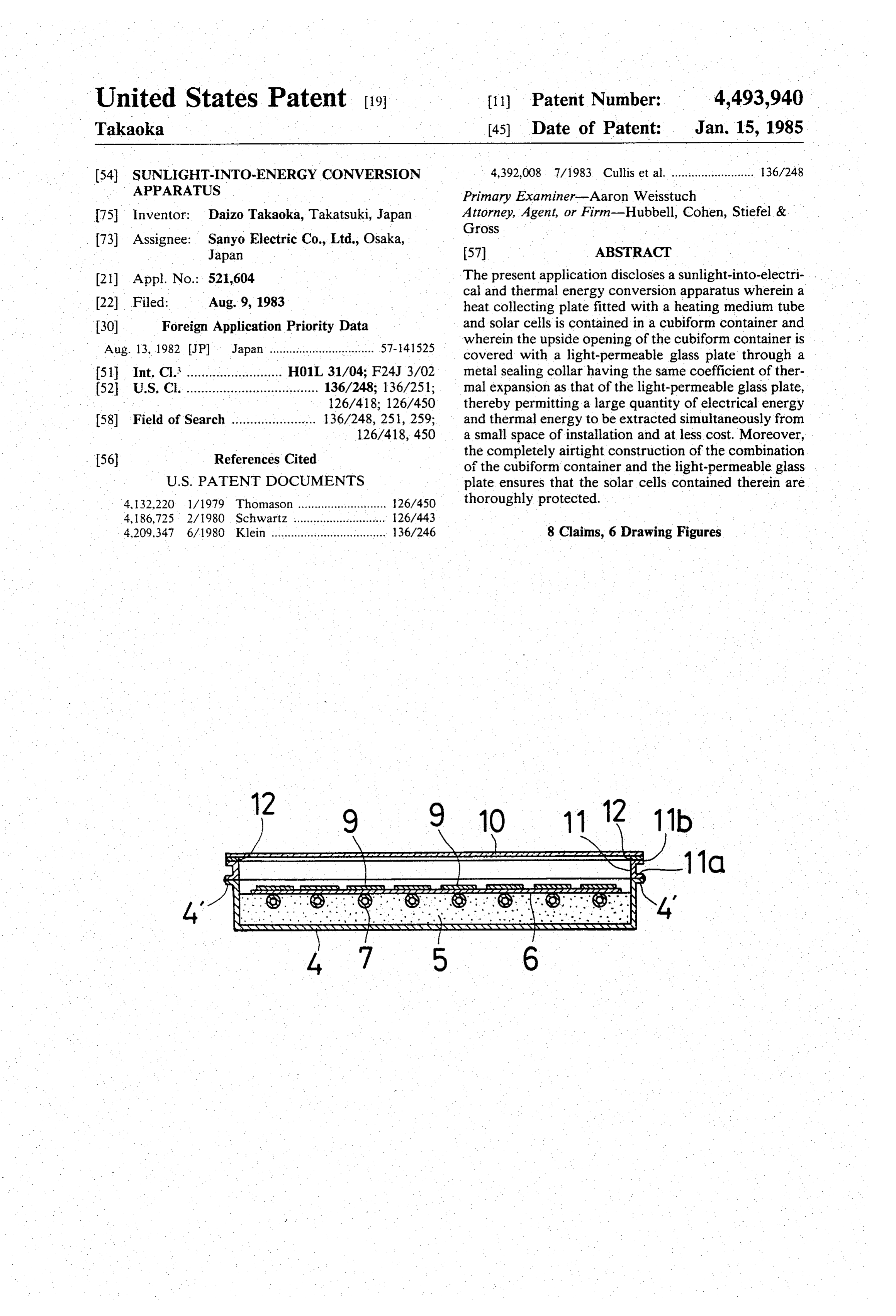
Japan 57) ABSTRACT (21) Appl. No.: 521,604 The present application discloses a sunlight-into-electri- . cal and thermal energy conversion apparatus wherein a 22 Filed: Aug. 9, 1983 heat collecting plate fitted with a heating medium tube 30 Foreign Application Priority Data and solar cells is contained in a cubiform container and Aug. 13, 1982 (JP) Japan ................................ 57-41525 wherein the upside opening of the cubiform container is covered with a light-permeable glass plate through a 51 Int. Cl. .......................... H01L 31/04; F24J 3/02 metal sealing collar having the same coefficient of ther 52 U.S. Cl. .................................... 136/248; 136/251; mal expansion as that of the light-permeable glass plate, 126/418; 126/450 thereby permitting a large quantity of electrical energy 58) Field of Search ....................... 136/248,251, 259; and thermal energy to be extracted simultaneously from 126/418, 450 a small space of installation and at less cost. Moreover, 56) References Cited the completely airtight construction of the combination of the cubiform container and the light-permeable glass
4,132,220 l/1979 Thomason ........................... 26/450 thoroughly protected.
4, 186,725 2/1980 Schwartz ............................ 26/443 4,209.347 6/1980 Klein ................................... 136/246 8 Claims, 6 Drawing Figures
Page 2
Drawing sheet — no readable text.
Page 3
Drawing sheet — no readable text.
Page 4
Drawing sheet — no readable text.
Page 5
The metal sealing collar employed in the present
SUNLIGHT-ENTO-ENERGY CONVERSION invention is a framework having a predetermined APPARATUS height. The metal material forming the Sealing collar is such that it has almost the same coefficient of thermal
BACKGROUND OF THE INVENTION 5 expansion as that of the light-permeable glass plate to 1. Field of the Invention which it is connected; in other words, it is selected in This invention relates to a sunlight-into-energy con connection with the material forming the light-permea version apparatus for simultaneously converting sun ble glass. For instance, a metal sealing collar made of nickel steel is used when soda-lime glass is used as the light energy into thermal and electrical energy, and O light-permeable more particularly to an apparatus of this kind incorpo nico is used whenglass, whereas the collar made offer borosilicate glass is employed.
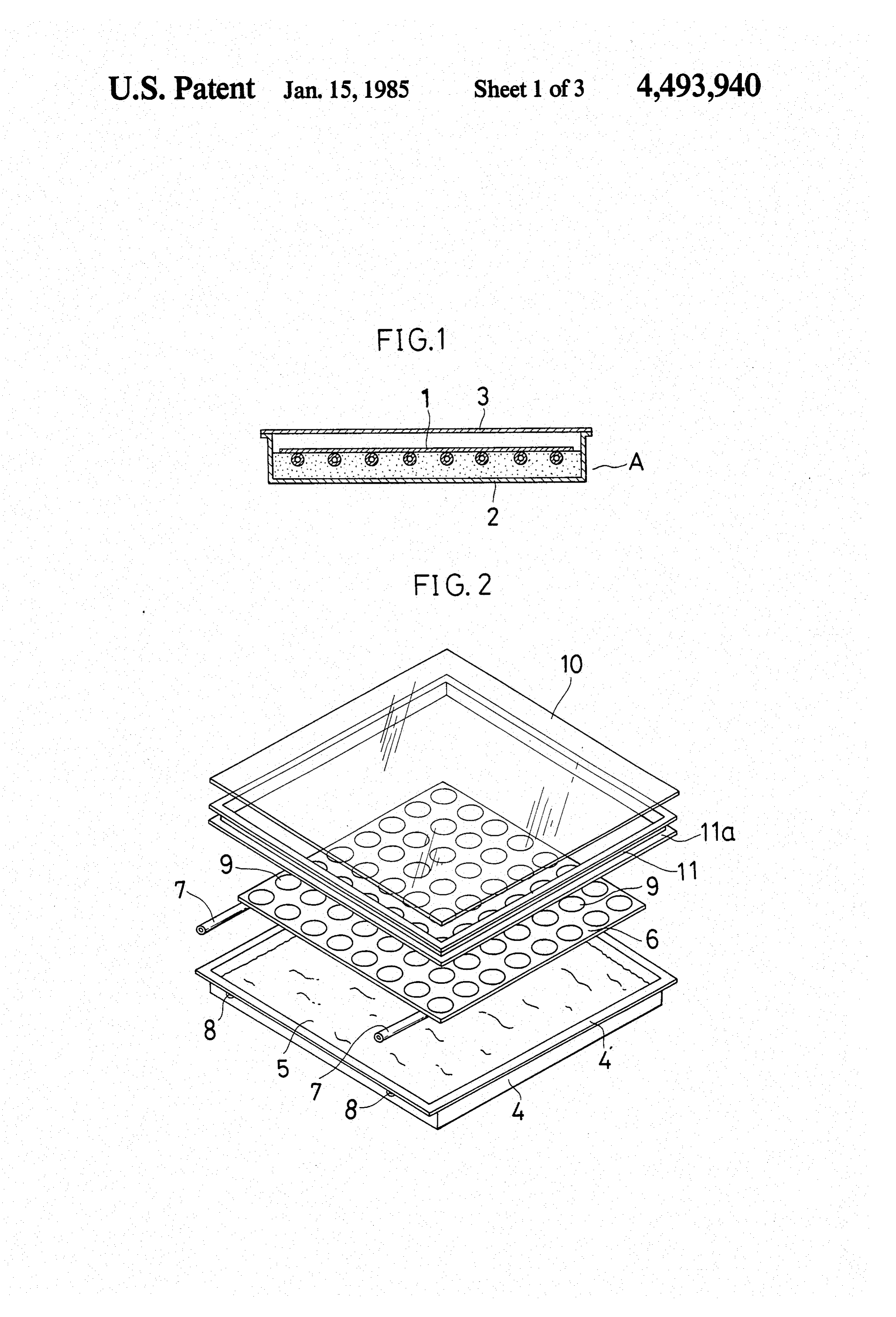
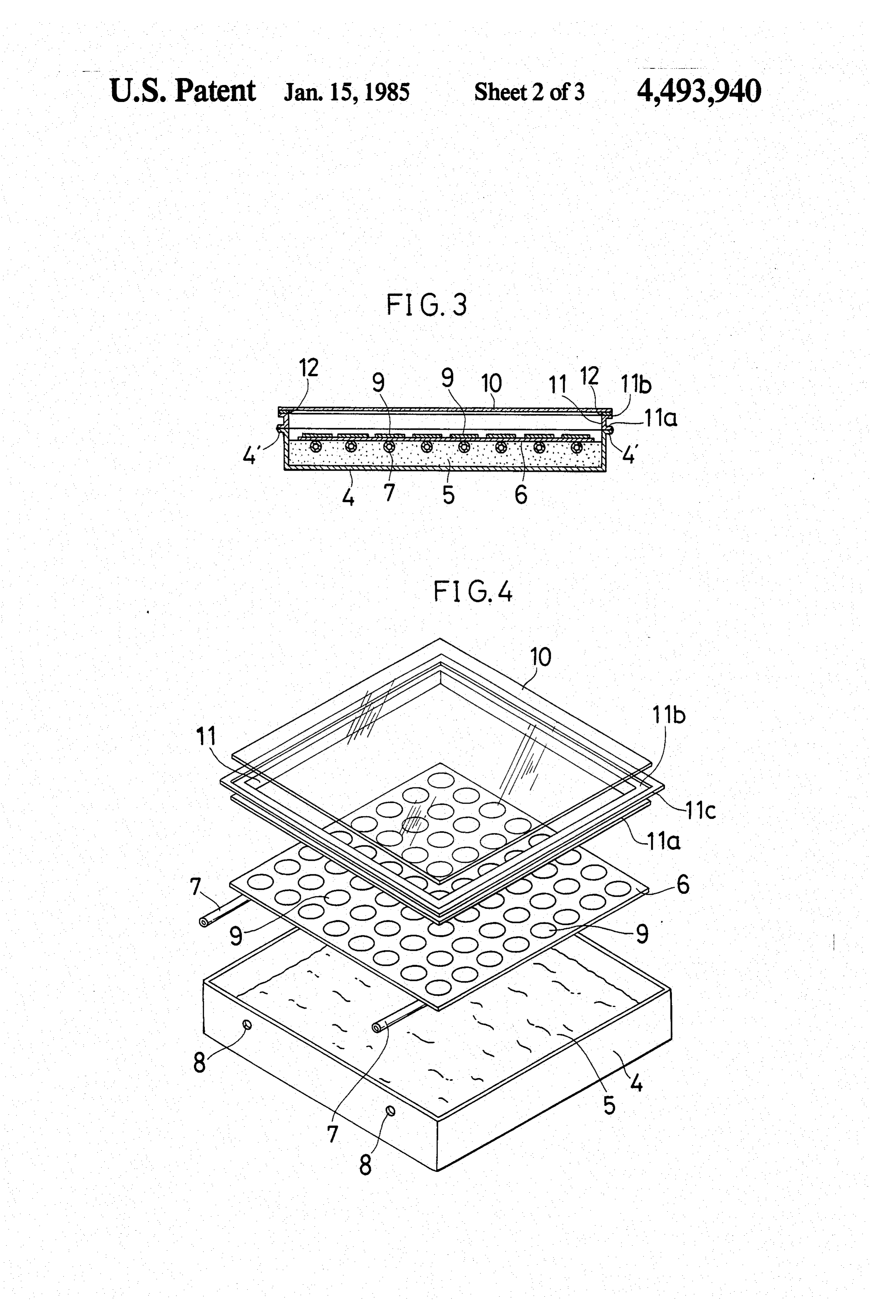
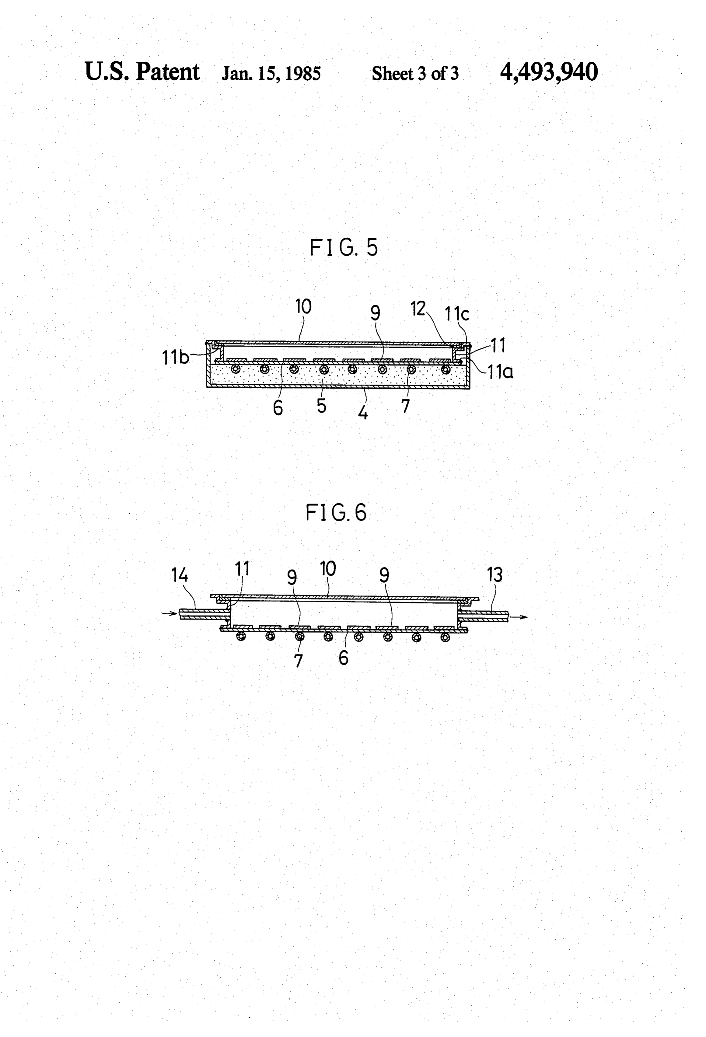
rating a heat collecting plate contained in a cubiform container and fitted with solar cells thereon and a heat BRIEF EDESCRIPTION OF THE DRAWINGS ing medium tube on its under surface so as to convert FIG. 1 is a longitudinal sectional view of a conven sunlight into electricity and heat efficiently without 5 tional solar heat collector.
Waste. FIG. 2 is an exploded perspective view of one em 2. Description of the Prior Art bodiment of the sunlight-into-energy conversion appa An apparatus for converting sunlight into electricity ratus according to the present invention. and heat was disclosed, for instance, in the Japanese FIG. 3 is a longitudinal sectional view of the example Official Patent Gazette No. 48227, 1980. The disadvan 20 shown in FIG. 2 when it is assembled. tage is that the use of heating medium tubes and Solar FIG. 4 is an exploded perspective view of another cells in a vacuum tube makes the apparatus of that type example of the sunlight-into-energy conversion appara extremely costly; besides, a number of converters re tus according to the present invention. quired for obtaining a large quantity of electricity and FIG. 5 is a longitudinal sectional view of the example calories make the apparatus further costly because the 25 shown in FIG. 4 when it is assembled. quantity of electricity and calories obtainable from a FIG. 6 is a longitudinal sectional view of still another single converter is quite small. example of the sunlight-into-energy conversion appara Accordingly, it appears feasible to mount Solar cells tus according to the present invention. on the surface of the heat collecting plate (1) of the well known natural circulation type heat collector (A) dis 30 DESCRIPTION OF THE PREFERRED closed in the Official Utility Model Gazette No. 236543, EMBODIMENTS 1981 as shown in FIG. 1, wherein a light-permeable Referring now to FIGS. 2 and 3, one preferred em glass plate (3) is installed to cover an upside opening bodiment of present invention will be described. A made in a cubiform container (2) constructed of an iron flange 4 is incorporated with the periphery of the up plate and the like by fastening the glass plate to the 35 side opening of a cubiform container 4 prepared by container with an organic sealant such as a silicon con processing a metal plate such as an iron plate into the pound or by mechanically fixing them. form of a dish. A heat collecting plate 6 which is an However, since the thermal expansivity of the glass aluminum, copper or iron plate is mounted on a heat plate (3) is by far different from that of the cubiform insulating material 5 such as glass wool contained in the container (2), thermal strain is produced. For this rea cubiform container 4. A heat collecting tube 7 made of son, the portion of the glass connected to the cubiform copper or aluminum and used as a heating medium tube container (2) is damaged and thus unable to make the is arranged in a zigzag line in a thermal conductive inside of the container (2) completely airtight. As a manner and both its ends are projected from holes 8 result, moisture allowed to permeate and condense made in a side wall of the cubiform container 4 and the therein causes the electrode of the solar cell to oxidize 45 projections are welded to the wall. A plurality of circu and ultimately the solar cell itself to deteriorate. This lar amorphous semiconductor solar cells 9 are formed problem has made it impossible to contain solar cells in on the heat collecting plate 6 and, as one of the elec a cubiform heat collector, though such a cubiform con trodes of each cell, an electrode layer is provided on the tainer is, in view of cost reduction, advantageous as an heat collecting plate 6 itself or via a thin insulating layer enclosure for installing the cells. 50 thereon, whereas the other electrode is provided on SUMMARY OF THE INVENTION each solar cell 9. A number of these cells 9 are properly connected together in series and parallel so as to corre
The present invention, therefore, has as its principal spond to the load requirements and led out by means of object the provision of a sunlight-into-energy conver leads (not shown) hermetically sealed up in the side wall sion apparatus wherein a heat collecting plate fitted 55 of the cubiform container 4. There are also provided a with a heating medium tube formed on its under surface light-permeable glass plate 10 covering the upside open and solar cells thereon is contained in a cubiform con ing of the cubiform container 4 and a metal sealing tainer through a heat insulating material, wherein the collar 11 lying between the glass plate 10 and the flange upside opening of the cubiform container is covered 4 on the periphery of the upside opening of the cubi with a light-permeable glass plate, wherein a metal 60 form container 4. The metal sealing collar 11 is con sealing collar is provided between the glass plate and structed of a material having a coefficient of thermal the periphery of the upside opening of the cubiform expansion roughly equal to that of the glass plate 10 and container, the coefficients of thermal expansion of the equipped with a lower flanged end 11a mounted on the metal sealing collar and the glass plate being almost flange 4 of the cubiform container 4 and an upper nearly equal, and wherein the sealing collar and the 65 flanged end 11b supporting the glass plate 10. glass plate and the periphery of the opening of cubiform The following exemplify two combinations of materi container are connected together, respectively, to make als for actual use for the glass plate 10 and the sealing the inside of the cubiform container airtight. collar 11.
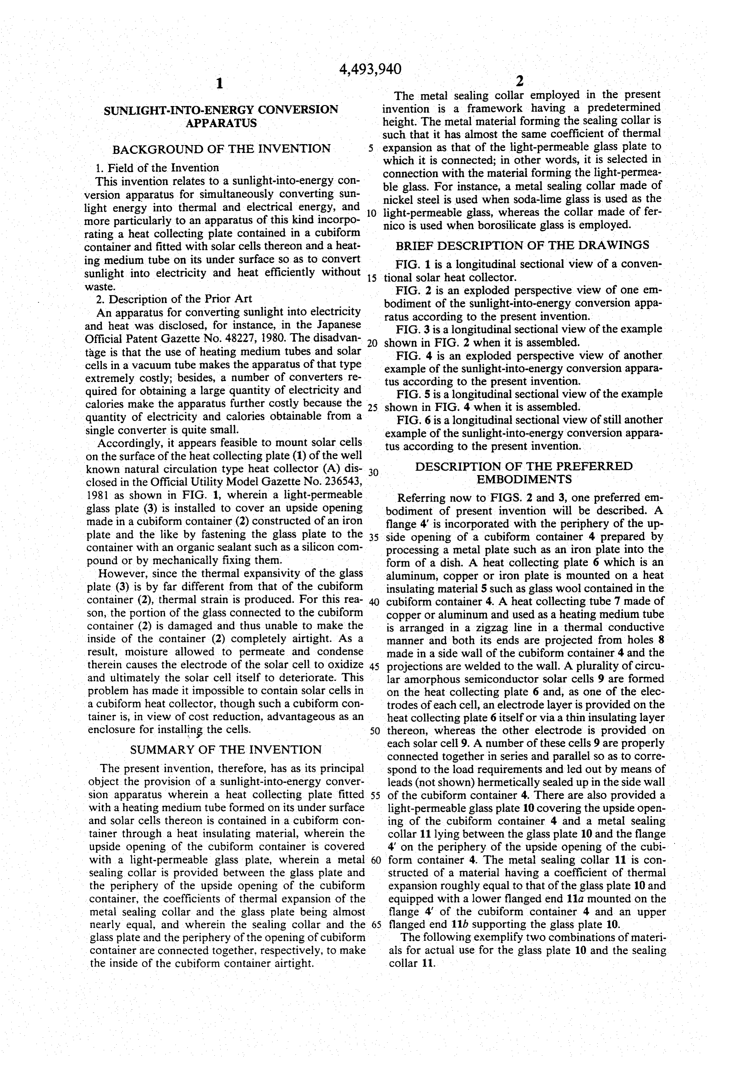
Page 6
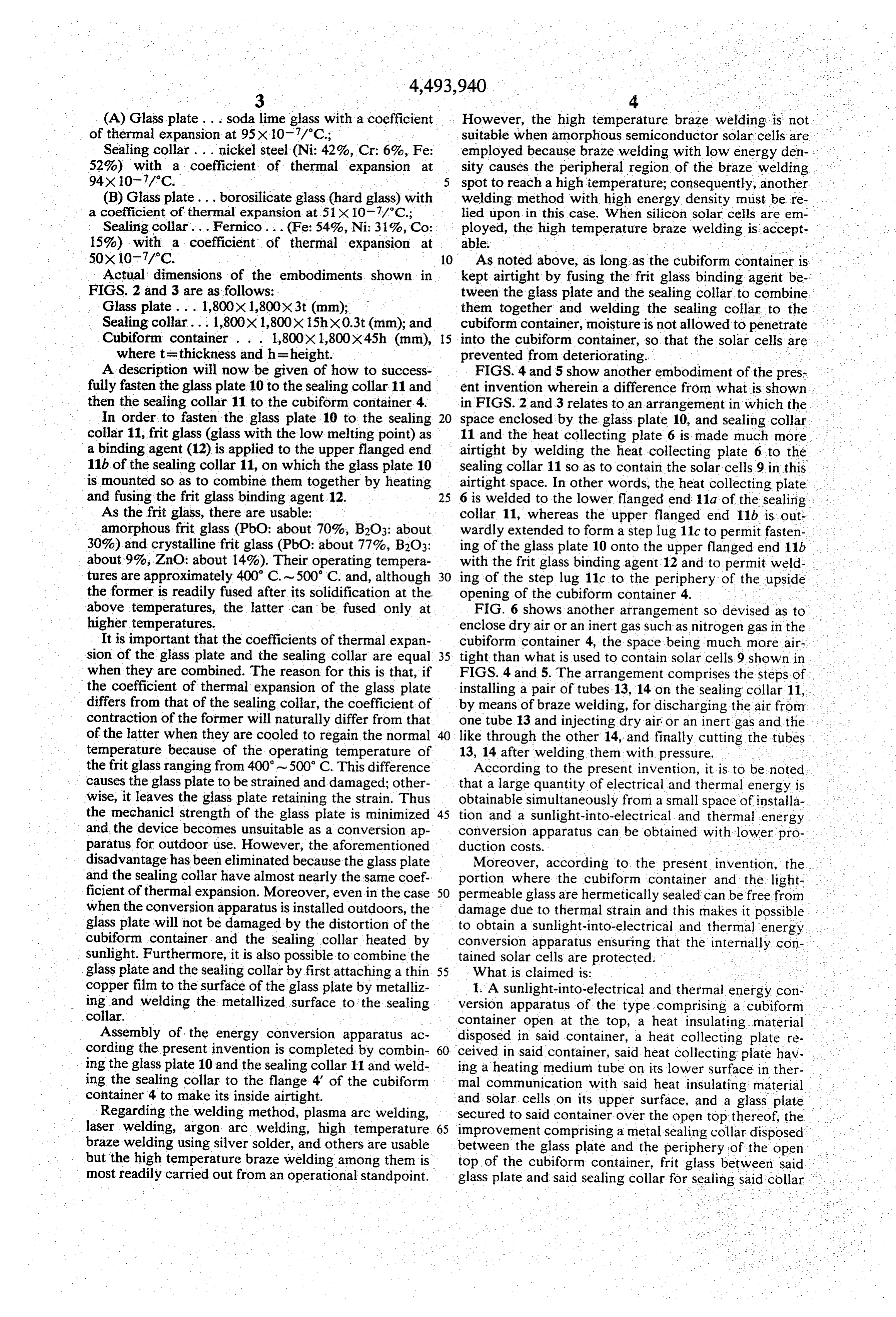
(A) Glass plate . . . soda lime glass with a coefficient However, the high temperature braze welding is not of thermal expansion at 95X 10.7/C.; suitable when amorphous semiconductor solar cells are Sealing collar... nickel steel (Ni: 42%, Cr: 6%, Fe: employed because braze welding with low energy den 52%) with a coefficient of thermal expansion at sity causes the peripheral region of the braze welding 94×10-7/°C. spot to reach a high temperature; consequently, another (B) Glass plate... borosilicate glass (hard glass) with welding method with high energy density must be re a coefficient of thermal expansion at 51 X 10.7/C.; lied upon in this case. When silicon solar cells are en Sealing collar... Fernico... (Fe: 54%, Ni: 31%, Co: ployed, the high temperature braze welding is accept 15%) with a coefficient of thermal expansion at able.
50x10-7/C. 10 As noted above, as long as the cubiform container is Actual dimensions of the embodiments shown in kept airtight by fusing the frit glass binding agent be FIGS. 2 and 3 are as follows: tween the glass plate and the sealing collar to combine Glass plate ... 1,800X 1,800X3t (mm); them together and welding the sealing collar to the Sealing collar... 1,800x1,800x15hX0.3t (mm); and cubiform container, moisture is not allowed to penetrate Cubiform container . . . 1,800X 1,800X45h (nm), 15 into the cubiform container, so that the solar cells are where t=thickness and h = height. prevented from deteriorating.
A description will now be given of how to success FIGS. 4 and 5 show another embodiment of the pres fully fasten the glass plate 10 to the sealing collar 11 and ent invention wherein a difference from what is shown. then the sealing collar 11 to the cubiform container 4. in FIGS. 2 and 3 relates to an arrangement in which the In order to fasten the glass plate 10 to the sealing 20 space enclosed by the glass plate 10, and sealing collar collar 11, frit glass (glass with the low melting point) as 11 and the heat collecting plate 6 is made much more a binding agent (12) is applied to the upper flanged end airtight by welding the heat collecting plate 6 to the 11b of the sealing collar 11, on which the glass plate 10 sealing collar 11 so as to contain the solar cells 9 in this is mounted so as to combine them together by heating airtight space. In other words, the heat collecting plate and fusing the frit glass binding agent 12. 25 6 is welded to the lower flanged end 11a of the sealing. As the frit glass, there are usable: collar 11, whereas the upper flanged end 11b is out amorphous frit glass (PbO: about 70%, B2O3: about wardly extended to form a step lug 11c to permit fasten 30%) and crystalline frit glass (PbO: about 77%, B2O3: ing of the glass plate 10 onto the upper flanged end 11b about 9%, ZnO: about 14%). Their operating tempera with the frit glass binding agent 12 and to permit weld tures are approximately 400 C. ~500 C. and, although 30 ing of the step lug 11c to the periphery of the upside the former is readily fused after its solidification at the opening of the cubiform container 4. above temperatures, the latter can be fused only at FIG. 6 shows another arrangement so devised as to higher temperatures. enclose dry air or an inert gas such as nitrogen gas in the It is important that the coefficients of thermal expan cubiform container 4, the space being much more air sion of the glass plate and the sealing collar are equal 35 tight than what is used to contain solar cells 9 shown in when they are combined. The reason for this is that, if FIGS. 4 and 5. The arrangement comprises the steps of the coefficient of thermal expansion of the glass plate installing a pair of tubes 13, 14 on the sealing collar 11, differs from that of the sealing collar, the coefficient of by means of braze welding, for discharging the air from contraction of the former will naturally differ from that one tube 13 and injecting dry air or an inert gas and the of the latter when they are cooled to regain the normal 40 like through the other 14, and finally cutting the tubes temperature because of the operating temperature of 13, 14 after welding them with pressure. -. the frit glass ranging from 400-500 C. This difference According to the present invention, it is to be noted causes the glass plate to be strained and damaged; other that a large quantity of electrical and thermal energy is wise, it leaves the glass plate retaining the strain. Thus obtainable simultaneously from a small space of installa the mechanicl strength of the glass plate is minimized 45 tion and a sunlight-into-electrical and thermal energy and the device becomes unsuitable as a conversion ap conversion apparatus can be obtained with lower pro paratus for outdoor use. However, the aforementioned duction costs.
disadvantage has been eliminated because the glass plate Moreover, according to the present invention, the and the sealing collar have almost nearly the same coef. portion where the cubiform container and the light ficient of thermal expansion. Moreover, even in the case 50 permeable glass are hermetically sealed can be free from when the conversion apparatus is installed outdoors, the damage due to thermal strain and this makes it possible: glass plate will not be damaged by the distortion of the to obtain a sunlight-into-electrical and thermal energy cubiform container and the sealing collar heated by conversion apparatus ensuring that the internally con sunlight. Furthermore, it is also possible to combine the tained solar cells are protected. - glass plate and the sealing collar by first attaching a thin 55 What is claimed is:
copper film to the surface of the glass plate by metalliz 1. A sunlight-into-electrical and thermal energy con ing and welding the metallized surface to the sealing version apparatus of the type comprising a cubiforn collar. container open at the top, a heat insulating material Assembly of the energy conversion apparatus ac disposed in said container, a heat collecting plate re cording the present invention is completed by combin 60 ceived in said container, said heat collecting plate hav ing the glass plate 10 and the sealing collar 11 and weld ing a heating medium tube on its lower surface in ther ing the sealing collar to the flange 4 of the cubiform mal communication with said heat insulating material . container 4 to make its inside airtight. and solar cells on its upper surface, and a glass plate Regarding the welding method, plasma arc welding, secured to said container over the open top thereof, the laser welding, argon arc welding, high temperature 65 improvement comprising a metal sealing collar disposed braze welding using silver solder, and others are usable between the glass plate and the periphery of the open but the high temperature braze welding among them is top of the cubiform container, frit glass between said most readily carried out from an operational standpoint. glass plate and said sealing collar for sealing said collar
Page 7
to said glass plate, the coefficients of thermal expansion 5. The apparatus of claim 1, wherein the heating of the metal collar and the glass plate being about equal, medium tube is arranged in a zigzag path on the lower and the sealing collar and the periphery of the open top surface of the heat collecting plate. of the cubiform container being sealed together by 6. The apparatus of claim 1, wherein the solar cells welding or soldering. are monocrystalline silicon solar cells or amorphous 2. The apparatus of claim 1, wherein the glass plate semiconductor solar cells.
and the metal sealing collar comprise, respectively, 7. The apparatus of claim 1, wherein dry air or an either soda-lime glass and nickel or borosilicate glass inert gas is enclosed in the cubiform container. and fernico. 8. The apparatus of claim 1, wherein the lower edge 3. The apparatus of claim 1, wherein the frit glass is O of the metal sealing collar is extended into the cubiform . amorphous frit glass or crystalline frit glass. container and continuously fastened to the heat collect 4. The apparatus of claim 1, wherein the soldering is ing plate. s effected by silver solder.

Provenance
- Collection
- Cited prior art
- Original PDF
- patentimages.storage.googleapis.com →
- Filed
- 1983-08-09
- Pages
- 7
- Method
- pdftotext (the PDF's own text layer) + pdftoppm 300dpi page scans
- Source
- Google Patents bibliographic record
- Granted
- 1985-01-15
- Inventors
- Daizo Takaoka; Sanyo Electric Co Ltd
- Transcribed from
- patentimages.storage.googleapis.com →