patent · US5228504
Heat exchanger
20 July 1993
Page 1 — bibliographic record
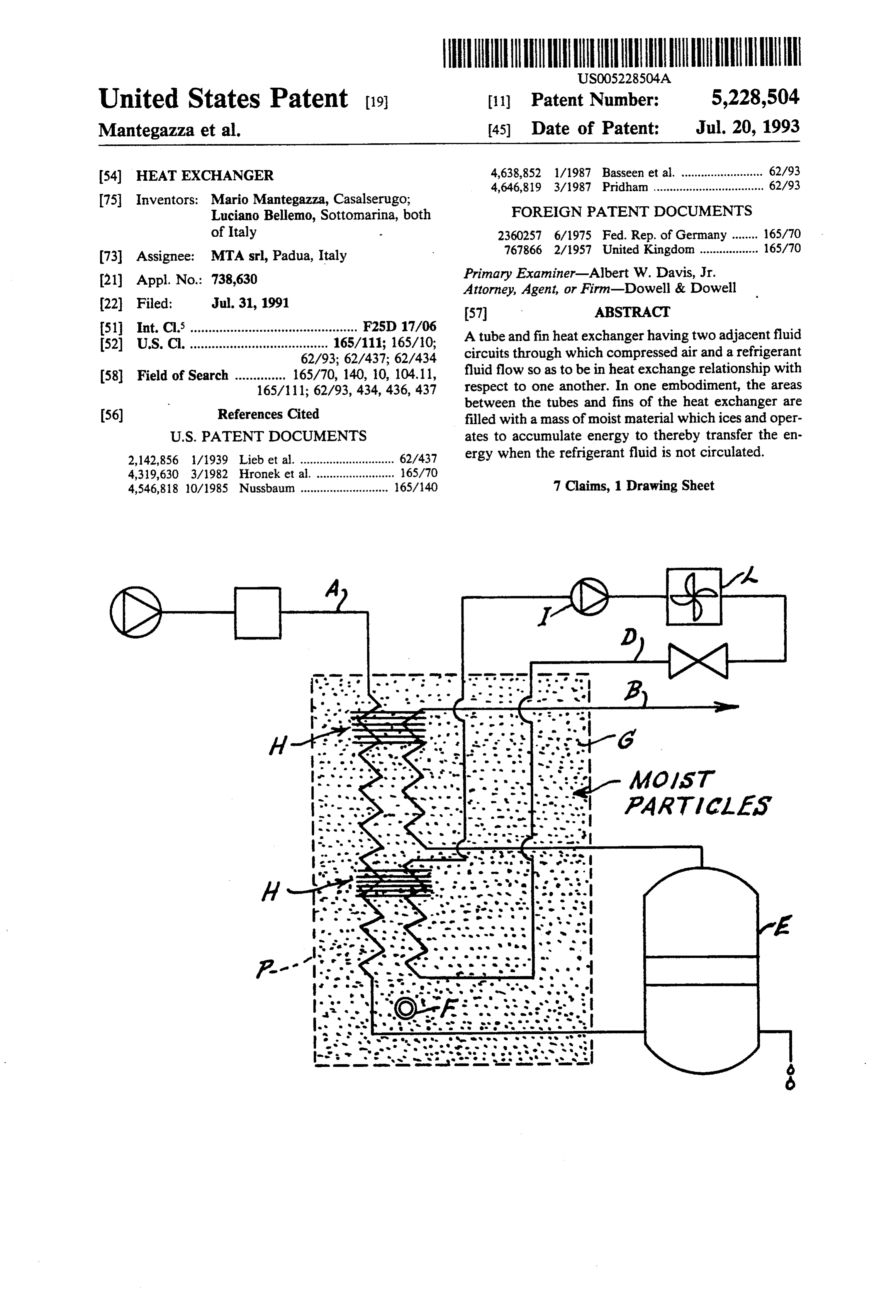
United States Patent (19) 11 Patent Number: 5,228,504 Mantegazza et al. 45) Date of Patent: Jul. 20, 1993 (54) HEAT EXCHANGER 4,638,852 l/1987 Basseen et al. ......................... 62/93 4,646,819 3/1987 Pridhan .................................. 62/93 75 Inventors: Mario Mantegazza, Casalserugo; FOREIGN PATENT DOCUMENTS Luciano Bellemo, Sottomarina, both of Italy 2360257 6/1975 Fed. Rep. of Germany ........ 65/70 767866 2/1957 United Kingdom...... ... 165/70 (73 Assignee: MTA srl, Padua, Italy (21) Appl. No.: 738,630 Primary Examiner-Albert W. Davis, Jr. Attorney, Agent, or Firm-Dowell & Dowell 22 Filed: Jul. 31, 1991 57 ABSTRACT 51 int. Cl. .............................................. F25D 17/06 (52) U.S. Cl. ...................................... 165/111; 165/10; A tube and fin heat exchanger having two adjacent fluid 62/93; 62/437; 62/434 circuits through which compressed air and a refrigerant (58) Field of Search .............. 165/70, 140, 10, 104.11, fluid flow so as to be in heat exchange relationship with 165/111; 62/93, 434, 436, 437 respect to one another. In one embodiment, the areas
References Cited between the tubes and fins of the heat exchanger are (56) filled with a mass of moist material which ices and oper
2,142,856 1/1939 Lieb et al. ............................. 62/437 ergy when the refrigerant fluid is not circulated. 4,319,630 3/1982 Hronek et al. ... 65/70 4,546,818 10/1985 Nussbaum ........................... 165/140 7 Claims, 1 Drawing Sheet
a an aus
a e sa - as wa aes
Page 2
Drawing sheet — no readable text.
Page 3
tween the first fluid and the tubes containing the second
HEAT EXCHANGER fluid, in order to obtain an efficient heat exchange, the two circuits have been placed very close to one another
BACKGROUND OF THE INVENTION and have been altered or staggered in a chess-board 1. Field of the Invention configuration. Also, the fins are made of high conduc tivity material, such as aluminum or copper, and are
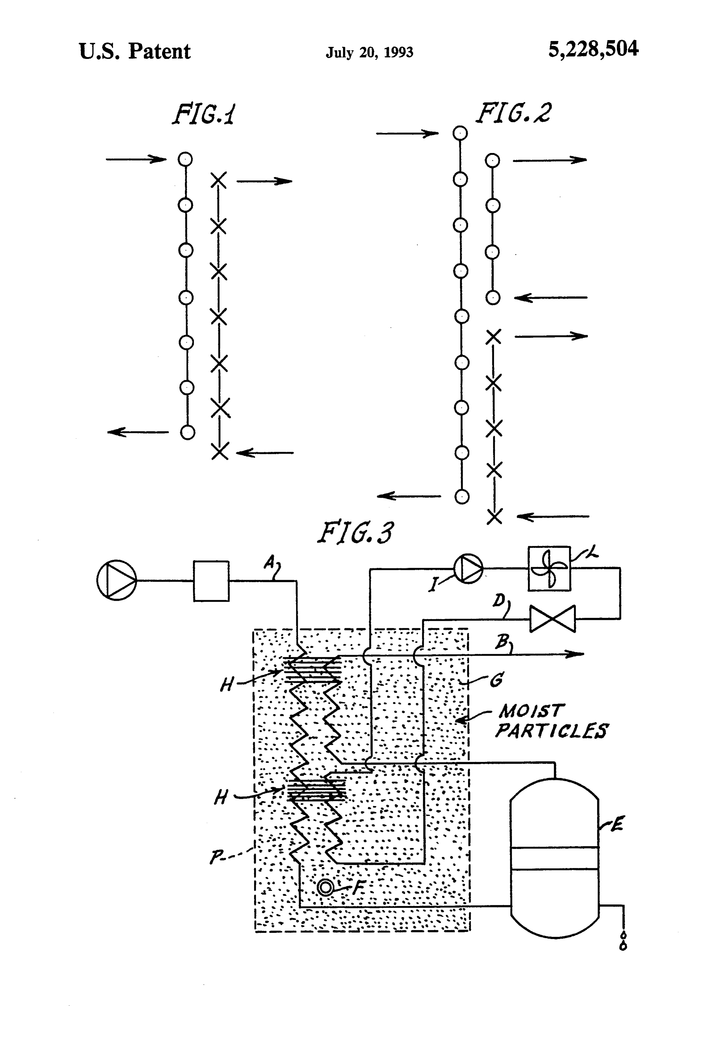
The present invention is directed to heat exchangers placed having tubes which are interconnected by heat transfer very close with respect to one another. fins. With respect to refrigerating cycle dryers for com 2. History of the Related Art pressed air which utilize both an evaporator and an In gas plants or in compressed gas mixture plants, the 10 air-to-air heat exchanger, the invention consists in di gas coming from the compressors contain a consider viding the fin and tube heat exchanger into three circuit able quantity of water in the form of vapor. Since this sections, as shown in FIG. 2. The moist air coming into vapor is noxious, it is necessary to condense the vapor the dryer enters the first circuit and a first section is and eliminate it from the gas flow. cooled by exchanging heat with the compressed air 15 which has passed through the same circuit. Subse
SUMMARY OF THE INVENTION quently, the first circuit is cooled by heat exchange with This invention is directed to a tube and fin heat ex a phase change refrigerant which flows through the changer wherein heat is exchanged between two fluids second circuit. Instead of a phase change refrigerant, it which flow through different circuits and which are 20 is possible to use a liquid, for example a mixture of water placed at an optimal distant from each other and and glycol, which is brought to a sufficiently low tem wherein each circuit extends directly through the fins of perature. In this manner a very compact fin and tube the exchanger. The moist air from a compressor passes heat exchanger has been constructed which includes through the first fluid circuit in such a nanner that the two heat exchange sections and in which the metallic dry outlet gas is used to precool the humid inlet gas 25 continuity is maintained by the fins between the tubes of before such inlet gas passes in heat exchange relation the sections thereby further enhancing heat exchange ship with the second fluid circuit which may be a refrig efficiencies.
erant circuit. The humid air at a temperature of 40° C. begins to Therefore, the first fluid circuit inside the tube and fin cool in the first section before coming into contact with heat exchanger is designed so that the conduits leading 30 the refrigerant fluid in the second fluid circuit. The air from the gas or fluid inlet are located near to conduits of the first circuit which is coming out at a temperature leading to a dry air outlet. This relationship allows heat of about 3" C. (dew point) having had the liquid re exchange between the humid inlet gas coming from a moved plant compressor and the dry outlet gas which has been about 3therefrom, C., before while the dry air, at a temperature of being expelled from the heat ex cooled within the exchanger. Consequently, the humid changer, flows through inlet gas is cooled transferring heat to the dry outlet gas 35 relationship with the inletcoils placed in heat exchange moist air. The dry air absorbs which is heated. A mass of material may be placed heat from the moist inlet air and is heated so that it between the fins of the heat exchanger and may be reaches temperature of about 20-30 C. soaked with water or other fluids to thereby increase In addition to the foregoing, the heat exchangers may the heat exchange efficiency of the heat exchanger. incorporate a thermal transfer mass which is in confor BRIEF DESCRIPTION OF THE DRAWINGS mity with an adjustment system of the refrigerant cir FIG. 1 is a schematic diagram of a first concept of the cuit. The thermal transfer mass can be made utilizing fluids or solid materials having small granularity. The present invention. granules should be small enough to guarantee the filling FIG. 2 is a schematic diagram of a second concept of of the spaces between the tubes and fins. Such materials the present invention. 45
FIG. 3 is a schematic diagram of a refrigerant cycle may be sand, metal powders, cement, agglomerates, dryer for compressed air in accordance with the teach hydraulic limes or the like, and which may be either dry ings of the present invention. or moist. The close spacing of the fins insures an optimal thermal exchange even in the presence of the thermal
DESCRIPTION OF THE PREFERRED SO mass created by these low conductivity materials. EMBODIMENT These materials are inexpensive, completely nontoxic Tube and fin heat exchangers are utilized with copper and easy to handle and introduce into the exchanger. tubes which may be, for example, inch diameter tubes Using a thermal mass soaked with water, it is possible and wherein the optimal pitch of the coiling of the tubes to reduce the temperature of the water to less than 0° C. is 25x12.5. The pitch of the tubes, however, can be 55 and thereby freeze it. This considerably increases the modified to 25X22 or 25X19. The fins are made from heat transfer efficiency of the thermal mass because of either aluminum or copper and are placed at a distance the latent heat offusion of the water. As the fluid to be of between 1.5 and 4 mm from one another. Optimum cooled is moist compressed air, a problem arises if the results can be obtained with the fins being placed at 1.5 water which condenses during the cooling phase mm from each other and with the tubes being pitched at freezes. Since the heat exchange process takes place 25X 12.5. because of a temperature gradient, it is possible to check In FIG. 1, the operation diagram of a first embodi the temperature of the thermal mass in order to stop the ment of the tube and fin heat exchanger is shown. The compressor (I) associated with the refrigerant circuit tubes through which the air to be dried flows are indi and thereby prevent icing of the tubes through which cated with a circle while the tubes through which the 65 the humid compressed air flows.
cooling fluid flows are indicated with a cross. A series By placing temperature sensors or probes in contact of parallel fins is placed at right angles with respect to with the fins of the heat exchanger inside the thermal the circuit tubes. Since there is no direct contact be mass, it is possible to adjust the temperature therein so
Page 4
that the temperature of the fluid to be cooled can be fluid circuit to said outlet section thereof and for con almost constant. The presence of ice in the mass placed necting said inlet section of said first fluid section to said between the fins increases the thermal efficiency and second fluid circuit, and a mass of particulate material lowers the average operating temperature of the system placed between said fins, whereby the gas is initially thereby prolonging the time in which the compressor of 5 cooled in heat exchange relationship with gas in the the refrigerant system is in an "off mode. second section of said first fluid circuit and is thereafter In FIG. 3 the operating circuit of the dryer of the further cooled by being in heat exchange relationship present invention is shown wherein (A) indicates the with said refrigeration medium.
inlet section of pipe of the moist compressed air fluid 2. The heat exchange apparatus of claim 1 in which circuit and (B) indicates the outlet dry air pipe section O said fins are spaced between 1.5 to 4 mm with respect to of the circuit. The two coil pipe sections are adjacent one another.
one another so that pipe (A) with the air to be cooled 3. The heat exchange apparatus of claim 1 in which transfers heat to pipe (B) of the outlet dry air with the said mass of material is selected from a group of materi heat being transferred through fins (H) of the heat ex als consisting of sand, metal powders, cement agglomer changer. Subsequently, pipe (A), in which the air to be 15 ates and hydraulic limes.
cooled flows, passes adjacent to the tubes (D) of a re 4. The heat exchange apparatus of claim 1 in which frigerant circuit through which the refrigeration fluid said mass of material is soaked with water. flows. Moisture is removed from the first fluid circuit in 5. The heat exchange apparatus of claim 4 including a condensate trap (E). A thermostat (F) is used to regu thermostat means disposed within said mass of material, late the temperature of a mass of material (G) placed a compressor means within said second fluid circuit,
between the tubes (D) of the refrigerant circuit and (A) said thermostat means being operable to control said and (B) of the first circuit of the fluid to be cooled. Coils compressor of said second fluid circuit in response to of the tubes (D), (A) and (B) and moist sand or other temperatures within said mass of material. material are contained in a housing the walls of which 6. The heat exchange apparatus of claim 1 including a are made and/or covered with a thermal insulating 25 condensate trap mounted between said inlet section and material (P). The mass of moist material which ices has a function of storing energy to transfer it to the first said7. outlet A heat section of said first fluid circuit.
exchange apparatus for cooling and recov fluid to be cooled when the refrigerant fluid circuit is ering moisture from a gas, comprising, a first fluid cir not circulating thereby reducing the amount of time the cuit including an inlet section and an outlet section in compressor (I) of the refrigerant circuit is operated. The which the gas to be
cooled is conveyed, a second fluid refrigerant circuit also incorporates a condenser (L).
These are schematic examples that should be suffi veyed, said inlet section aofrefrigeration circuit through which medium is con said first fluid circuit initially cient for a skilled reader to understand the invention.
There could be some variations which will not influ being disposed adjacent said second outlet section ence the substance of the invention. 35 thereof so as to be in heat exchange relationship there We claim: with, said inlet section thereafter extending adjacent 1. A heat exchange apparatus for cooling and recov said second fluid circuit so as to be in heat exchange ering moisture from a gas, comprising, a first fluid cir relationship therewith, heat conducting fins extending cuit including an inlet section and an outlet section in between and connecting said inlet section of said first which the gas to be cooled is conveyed, a second fluid fluid circuit to said outlet section thereof and for con circuit through which a refrigeration medium is con necting said inlet section of said first fluid section to said veyed, said inlet section of said first fluid circuit initially second fluid circuit, and a freezable liquid being dis being disposed adjacent said second outlet section posed between said fins, whereby the gas is initially thereof so as to be in heat exchange relationship there cooled in heat exchange relationship with gas in the with, said inlet section thereafter extending adjacent 45 second section of said first fluid circuit and is thereafter said second fluid circuit so as to be in heat exchange further cooled by being in heat exchange relationship relationship therewith, heat conducting fins extending with said refrigeration medium. sk between and connecting said inlet section of said first
Provenance
- Collection
- Cited prior art
- Original PDF
- patentimages.storage.googleapis.com →
- Filed
- 1991-07-31
- Pages
- 4
- Method
- pdftotext (the PDF's own text layer) + pdftoppm 300dpi page scans
- Source
- Google Patents bibliographic record
- Granted
- 1993-07-20
- Inventors
- Mario Mantegazza; Luciano Bellemo; MTA SpA
- Transcribed from
- patentimages.storage.googleapis.com →