patent · US4094148
Thermal storage with molten salt for peaking power
13 June 1978
Page 1 — bibliographic record
United States Patent (19) 11) 4,094,148 Nelson 45 June 13, 1978 54 THERMAL STORAGE WITHMOLTENSALT 56 References Cited FOR PEAKING POWER U.S. PATENT DOCUMENTS 75 Inventor: Hazen E. Nelson, Acton, Mass. 3,299,945 l/1967 Rice et al. ................................ 165/4
3,974,642 8/1976 Pacault .............................. 60/659 X 73 Assignee: Stone & Webster Engineering
Corporation, Boston, Mass. Primary Examiner-Allen M. Ostrager
Attorney, Agent, or Firm-Morgan, Finnegan, Pine, 21 Appl. No.: 777,458 Foley & Lee
22 Filed: Mar. 14, 1977 An improvement in the process for the generation of electrical power in which heat released by exhaust gases (51) Int. C.’......................... F01K 3/00; F01K 23/10 derived from the combustion of gaseous products in a 52 U.S. C. ........................................ 60/652; 60/659; coal gasification process is stored and utilized to gener 60/39.18 B; 60/655 ated increased electrical power during peak demand (58 Field of Search .......... 60/652, 659, 655, 39.18 B, periods.
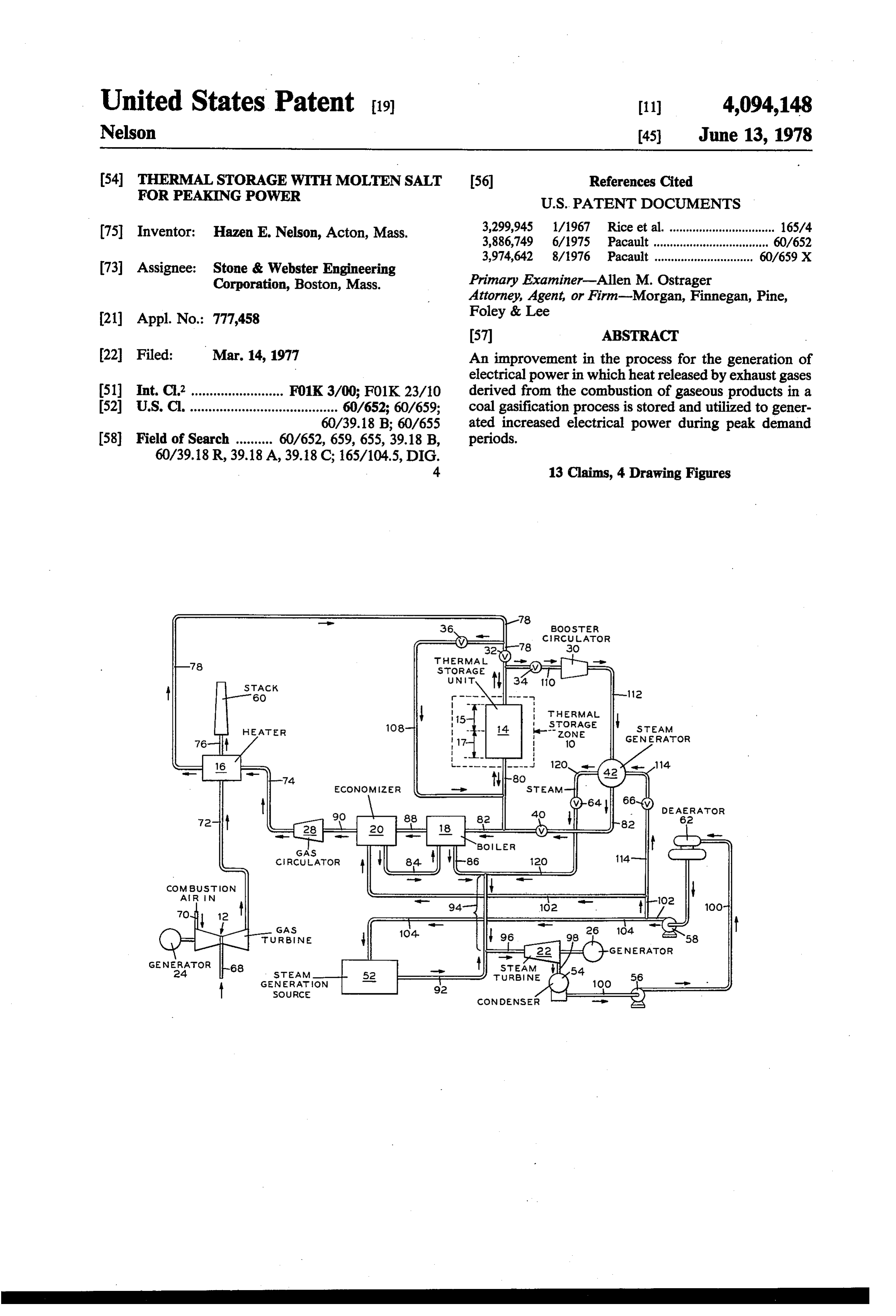
Booster circuA or
terMA
SORAGE
GENERAOR
Generation source
Page 2
Drawing sheet — no readable text.
Page 3
Drawing sheet — no readable text.
Page 4
periods while storing energy for use at peak demand
THERMAL STORAGE WITH MOLTEN SALT FOR periods to generate increased electrical power. PEAKING POWER Still another object of the invention is to provide a
FIELD OF THE INVENTION
heat storage system which can be readily integrated into 5 an electrical power generation process, which uses coal
The present invention relates to the generation of as the energy source, to achieve the more economical electrical power. production of electrical power at peak demand periods. In one of its aspects, the invention relates to the in Broadly contemplated, the present invention pro creased generation of electrical power at peak demand vides an improvement in a process for the generation of periods. O electrical power wherein coal is gasified to produce a In a more specific aspect, the present invention re stream of heated fuel gases. The heated fuel gases are lates to the storage of heat in a thermal storage medium used to drive a gas turbine-generator which produces which heat is utilized at peak demand periods to gener electrical power during peak and non-peak electrical ate increased electrical power. power demand periods. The exhaust gases released 15 from the gas turbine are passed in heat exchange rela
BACKGROUND OF THE INVENTION tionship with a heat exchange gas to heat said heat As is well known to those skilled in the art, conven exchange gas. The heated heat exchange gas is then tional electrical power generation facilities in many introduced into a thermal storage zone wherein during instances utilize fuel oil or natural gas as the source of non-peak demand periods the major portion of the heat energy for generating electrical power. In the past these 20 released by said heated heat exchange gas is stored in said thermal storage zone for use during peak demand fuels, which possess properties that make them particu periods.
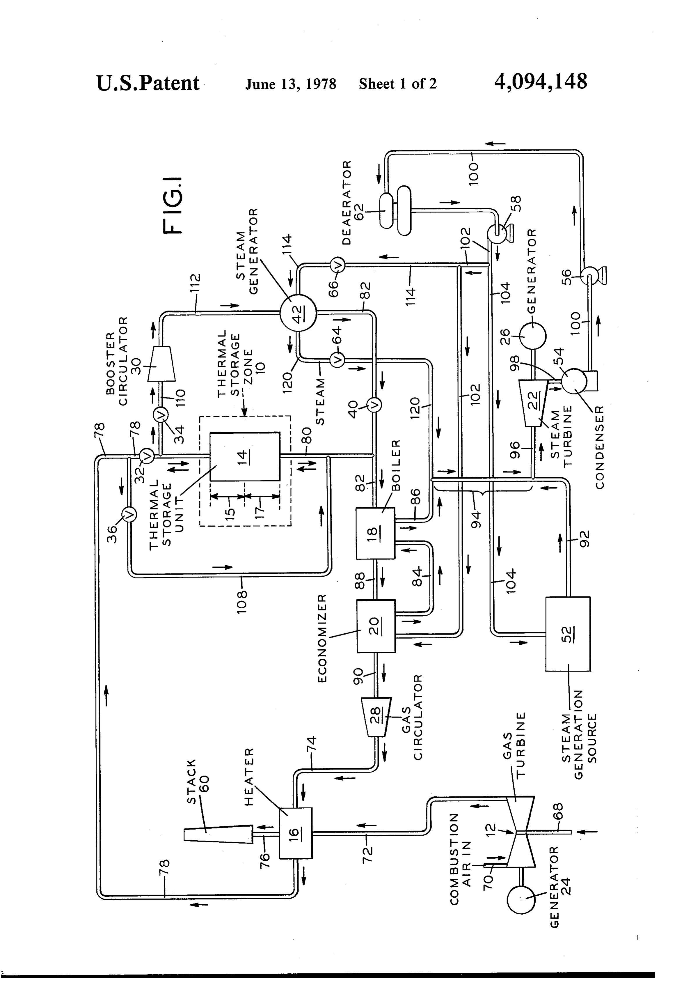
larly suitable for supplying increased electrical power substanceThe thermal storage zone uses a heat storage such as sodium hydroxide which absorbs and during peak demand periods, were relatively inexpen retains large sive and in plentiful supply. Unfortunately, the high 25 to liquid state.quantities of heat by transition from solid cost of petroleum crude oil and natural gas, and the The heat exchange gas is then introduced into a first uncertainty of our sources of these fuels, now necessi steam generation zone to generate steam for producing tates that different energy sources be explored and new electrical techniques for effective utilization of both old and new periods. power during peak and non-peak demand sources of energy be developed. 30 During peak demand periods, the heated heat ex Coal, which is in great supply and is relatively inex change pensive, is among the materials suggested by the art as age aregas and additional heat exchange gas from stor passed in reverse flow through the thermal a source of energy for the generation of electrical storage zone to absorb power. Coal has the capacity to be gasified and used to heat exchange gas is the stored heat. The now heated delivered to steam generation drive gas turbines which can be implemented for the 35 equipment to generate steam for producing increased production of electrical power. In operation, the gas electrical power during peak demand periods. turbines develop low levels of waste heat which, under conventional techniques, has been rejected to the atmo DESCRIPTION OF THE DRAWING sphere or in part recovered by generating steam for FIG. 1 is a schematic representation illustrating one additional power regeneration. Unfortunately, the tech 40 embodiment of the invention.
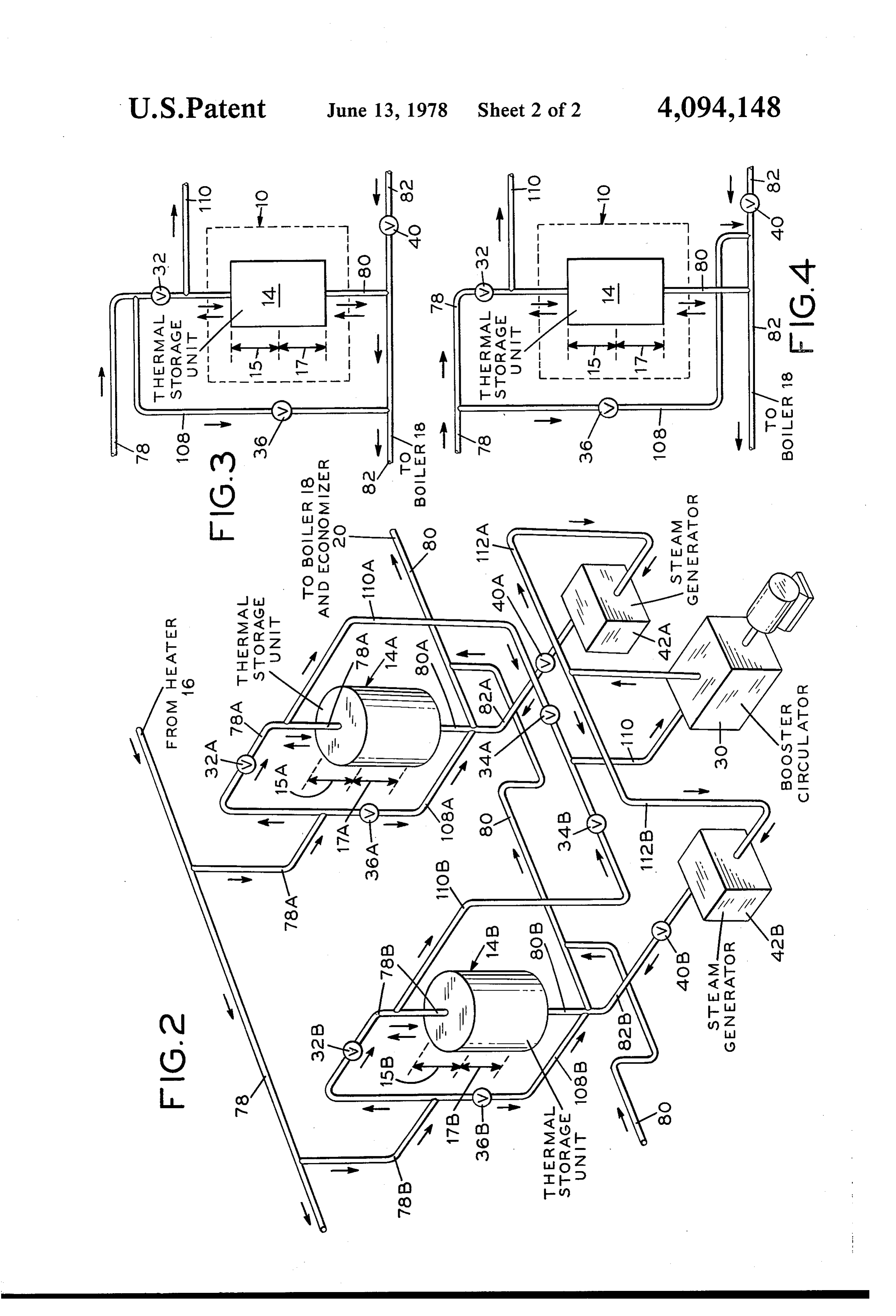
niques for the gasification of coal for the generation of FIG. 2 is a isometric representation illustrating an electrical power have not been entirely satisfactory, due arrangement of some of the apparatus parts for an em in part to the relative inability of these techniques to bodiment of the invention utilizing two thermal storage vary electrical power output to follow the system load units.
demands and supply increased electrical power at peak 45 FIG. 3 is a partial schematic representation of an demand periods. alternate arrangement for introducing heat exchange SUMMARY OF THE INVENTION gas into boiler 18 and thermal storage zone 10. FIG. 4 is a partial schematic representation of an
It is, therefore, an object of the present invention to other alternate arrangement for introducing heat ex provide a method for generating electrical power using 50 change gas into boiler 18 and thermal storage zone 10. coal as the source of energy, which method is readily DETAILED DESCRIPTION OF THE capable of generating increased electrical power at peak INVENTION demand periods.
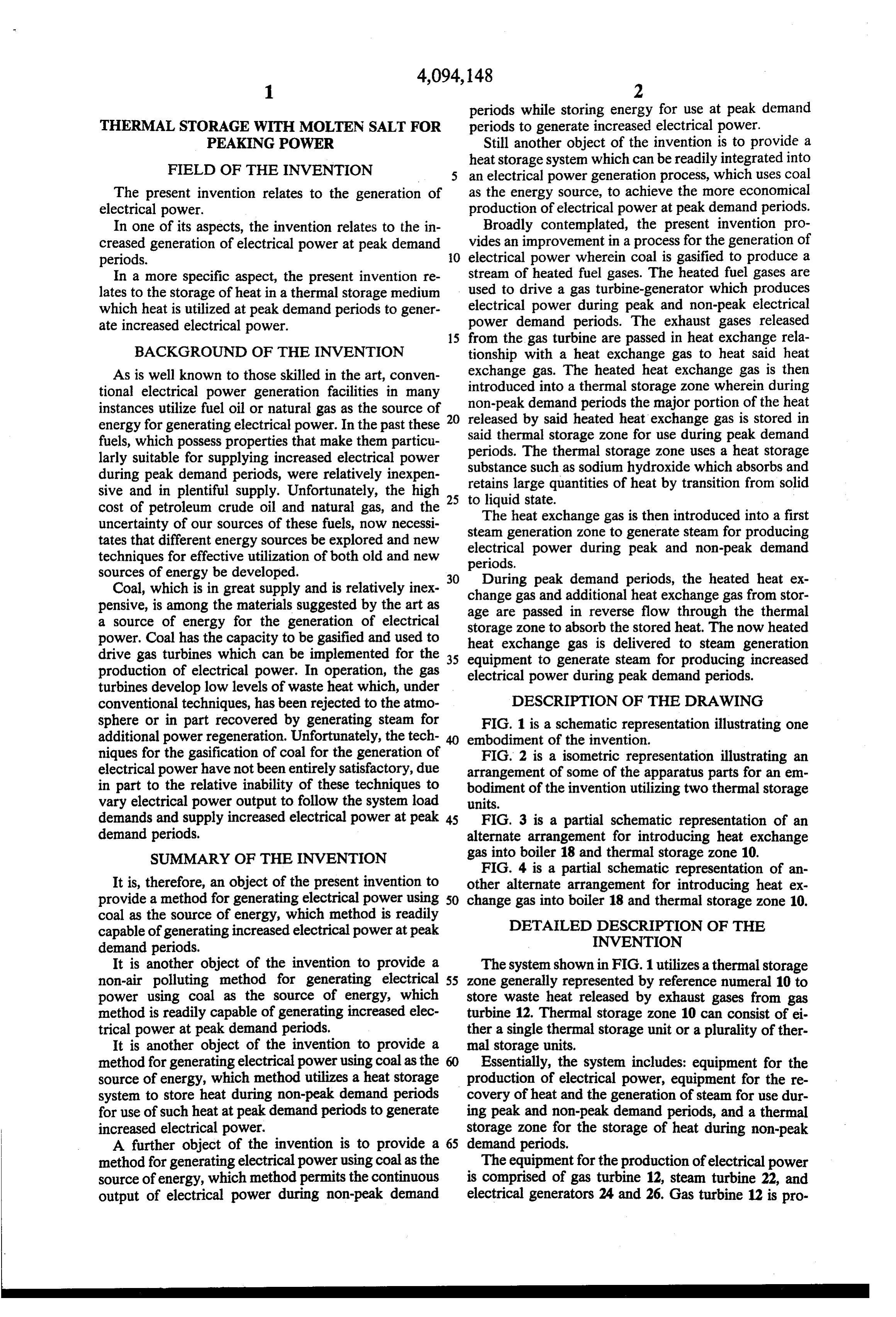
It is another object of the invention to provide a The system shown in FIG. 1 utilizes athermal storage non-air polluting method for generating electrical 55 zone generally represented by reference numeral 10 to power using coal as the source of energy, which store waste heat released by exhaust gases from gas method is readily capable of generating increased elec turbine 12. Thermal storage zone 10 can consist of ei trical power at peak demand periods. ther a single thermal storage unit or a plurality of ther It is another object of the invention to provide a mal storage units.
method for generating electrical power using coal as the Essentially, the system includes: equipment for the source of energy, which method utilizes a heat storage production of electrical power, equipment for the re system to store heat during non-peak demand periods covery of heat and the generation of steam for use dur for use of such heat at peak demand periods to generate ing peak and non-peak demand periods, and a thermal increased electrical power. storage Zone for the storage of heat during non-peak A further object of the invention is to provide a 65 demand periods.
method for generating electrical power using coal as the The equipment for the production of electrical power source of energy, which method permits the continuous is comprised of gas turbine 12, steam turbine 22, and output of electrical power during non-peak demand electrical generators 24 and 26. Gas turbine 12 is pro
Page 5
vided with a combustion air intake line 70, a fuel gas - The exhaust gases leave heater 16 through line 76 at inlet line 68, and an exhaust gas outlet line 72. Steam a temperature of about 425' to 600 F. and approxi turbine 22 is provided with a steam inlet line 96 and an mately atmospheric pressure and are directed into stack outlet line 98. 60 where they are released to the atmosphere. Thermal storage zone 10 is provided with one or 5 The heat exchange gas having been heated to a tem more thermal storage units 14, a heat exchange gas inlet perature of about 500 to 1000'. F. exits heater 16 line 78, and a heat exchange gas outlet line 80. Valves through line 78 and is directed into thermal storage 32, 34, 36, and 40 associated respectively with lines 78, Zone 10.
110, 108, and 82 are provided to selectively deliver As used herein the term "peak demand periods' is waste heat to and remove stored heat from thermal O meant to connote those periods in which there is an storage zone 10. increased demand for electrical power over and above The waste heat recovery and steam generation equip the amount of power normally generated by an electri ment used during both peak and non-peak demand peri cal power producing process. The term "non-peak de ods is comprised of heater 16; boiler 18; economizer 20; mand periods' is meant to connote those periods at gas circulator 28; heat exchange gas lines 74,78, 80, 82, 15 which an electrical power producing process is produc 88, and 90; water lines 84, 100, and 102; and steam lines ing the amount of power normally generated by such a 86, 94, 96, and 120. process.
The waste heat recovery and steam generation equip During non-peak demand periods, a portion of the ment activated during peak demand periods is com heat obtained by the heat exchange gas in heater 16 is prised of booster circulator 30; steam generator 42; heat 20 stored in thermal storage zone 10 for use of such stored exchange gas lines 82, 108, 110, and 112, water line 114; heat to generate increased electrical power at peak steam line 120; and valves 64 and 66 associated with demand periods. Thus, as will be seen from FIG. 1, lines 120 and 114, respectively. situated immediately outside thermal storage zone 10 is As shown in FIG. 1, fuel gas from a coal gasification process (not shown) is directed through line 68 at a 25 anumerals system of valves generally indicated by reference 32, 34, 36, and 40. These valves are conven temperature of about 50 to 130 F. into gas turbine 12 tional and are adapted to either permit the flow of fluid wherein the fuel gas is combined with combustion air which enters gas turbine 12 through line 70 at a temper therethrough or alternatively can be activated to pre ature of about 50 to 130 F. Gas turbine 12 is a conven demand periods,passage vent fluid flow the therethrough. During non-peak heat exchange gas from heater 16 is tional gas turbine which normally includes a combus 30 tion chamber wherein fuel gas is reacted with combus introduced into thermal storage zone 10 through line 78 tion air. As is known, gas turbines can be used as a so that a portion of the heat obtained by the heat ex driving force for operating electric power producing change gas can be stored. Accordingly, in this situation generators. Thus, associated with gas turbine 12 is a (non-peak demand periods) valve 32 would be activated conventional generator 24 which is suitable for generat 35 to the open position and valves 34 and 36 would be ing large amounts of electrical power by techniques activated to the closed position; the heat exchange gas is which are well known to those skilled in the art. thus directed from heater 16 through line 78 into ther Operation of gas turbine 12 produces exhaust gases mal storage zone 10.
which must be removed from the gas turbine. Accord Thermal storage zone 10 comprises at least one ther ing to some conventional techniques, the exhaust gases mal storage unit 14 as indicated in FIG. 1, but it should are either discharged directly to the atmosphere or be expressly understood that a plurality of thermal stor alternatively are cooled prior to release to the atmo age units can be utilized in the process of the present sphere by a cooling medium such as water. According invention; the number of units used and the size of these to the present invention, the heat transferred from the units will depend in part on the quantity of heat to be exhaust gases is stored, to be utilized to generate in 45 stored and the nature of the thermal storage medium creased electrical power at peak demand periods as will contained in the units.
be explained in detail hereafter. Thermal storage unit 14 is an apparatus capable of Thus, the exhaust gases, which are generally at a effecting heat transfer between the heat exchange gas temperature of about 950 to 1150 F., exit gas turbine and a thermal storage medium. Merely as illustrative, 12 through line 72 and are directed into heater 16 SO thermal storage unit 14 can be a conventional vertical wherein the exhaust gases are passed in indirect contact shell and tube heat exchanger wherein the thermal stor with a heat exchange gas which enters heater 16 age medium, such as an inorganic salt, is stored in the through line 74 at a temperature of about 375 to 400 F. shell side of the heat exchanger and the heat exchange and at a pressure of about 18 to 40 p.s.i.a. The heat heat gas is passed through the tubes. The thermal storage exchange gas introduced into heater 16 can comprise 55 medium should possess the requisite physical properties air, helium, hydrogen, nitrogen, argon, carbon dioxide, and in addition have the appropriate heat capacity to low oxygen content combustion products of hydrocar enable it to pass from solid to liquid phase upon being bons and mixtures of the foregoing. The preferred heat heated by the heat exchange gas. These compositions exchange gas is air. should possess high heats of fusion, broad operative Heater 16 is a conventional heat exchanger and can temperature ranges, and relative inertness. Inorganic be of type generally known in the art as the flat plate compounds, preferably alkalimetal hydroxides, particu type heat exchanger. In FIG. 1, one heater is shown but larly sodium hydroxide, are preferred as the thermal it is to be understood that more than one heater can be storage medium.
used, depending upon the system load demand and the The heat exchange gas introduced into thermal stor capacity of the heater employed. 65 age Zone 10 through line 78 is directed into thermal As a result of the indirect contacting with the exhaust storage unit 14 where it is passed in indirect contact gases in heater 16, the heat exchange gas is heated to a with the thermal storage medium. As a result, the ther temperature of about 500' to 1000 F. mal storage medium is heated to a temperature of about
Page 6
450 to 900' F. which is sufficient to melt the solid backflow. It will be seen that all of the heat exchange thermal storage medium to a liquid. gas from line 78 is directed into upper portion 15A of During the melting procedure the thermal storage thermal storage unit 14A where it is passed in indirect medium in the upper portion of thermal storage unit 14 5 contact with the thermal storage medium until the ther should be melted first. In this way, the possibility that mal storage medium is heated to a temperature of about the thermal storage medium might cause damage to the 450° to 900' F. The heat exchange gas is withdrawn unit by shifting or falling during melting is minimized. from thermal storage unit 14A through line 80A and is Similarly, during the solidification procedure, which thereafter directed through line 80 into boiler 18 to takes place during peak demand periods, the thermal generate steam as will be discussed hereafter. storage medium in the lower portion of thermal storage 10 After thermal storage unit 14A is charged with the unit 14 should be solidified first to guard against the appropriate amount of heat, the heat exchange gas is possibility of damage to the unit caused by the solidified directed into thermal storage uit 14B. This is accom thermal storage medium shifting or falling during the plished by opening valve 32B and closing valves 32A, solidification procedure. 34B, and 40B. The heat exchange gas is then passed Thus, as will be seen in FIG. 1, during non-peak 15 through thermal storage unit 14B until it also has ab demand periods the heat exchange gas entering thermal sorbed the appropriate amount of heat. If more than storage unit 14 is introduced into the upper portion 15 two thermal storage units are employed, the procedure of thermal storage unit 14 and withdrawn from the unit for storing heat in the thermal storage units, one unit at at the lower portion 17. a time, described immediately above, is continued until The heat exchange gas leaving the lower portion 17 20 all of the units are charged with the appropriate amount of thermal storage unit 14 is directed into boiler 18 of heat.
wherein additional heat obtained by the heat exchange As the heat exchange gas leaves thermal storage Zone gas in heater 16 is utilized to generate steam as will be 10 there is still sufficient heat present in the heat ex discussed hereafter. change gas to generate steam, which steam can be used In those cases where more than one thermal storage 25 to operate steam turbine 22 for the generation of electri unit is utilized, it is desirable to introduce the heat ex cal power.
change gas into the thermal storage units, one unit at a Referring again to FIG. 1, during non-peak demand time, until all of the units are charged with the appropri periods valve 40 in line 82 is closed. Accordingly, the ate amount of heat. Among the techniques by which heat exchange gas is withdrawn from thermal storage this can be achieved is to provide line 78 as the source 30 of heat exchange gas for each thermal storage unit and zone 10 through line 80 at a temperature of about 500 to 600 F. and is introduced into boiler 18 where it is to position valves corresponding to valves 32, 34, 36, passed in indirect contact with water which enters and 40 in FIG. 1 for each thermal storage unit em ployed, Hence, when more than one thermal storage 35 boiler 18 through line 84 at a temperature of about 350 unit is utilized, each thermal storage unit, e.g., thermal water is F.converted to 575 As a result of this indirect contacting, the into steam, which leaves boiler 18 storage unit 14A, will have associated with it valves through line 86 at a temperature of about 350 to 575° F. 32A, 34A, 36A, and 40A to control the flow of heat and a pressure of about 135 to 1275 p.s.i.a. The steam exchange gas from line 78. When a particular thermal storage unit is receiving heat exchange gas, the valve produced be used as is directed into steam turbine 22 where it will a source of energy for generating electrical for that unit corresponding to valve 32 in FIG. 1 would be in the open position and the valves corresponding to power. The cooled heat exchange gas exits boiler 18 through valves 34, 36, and 40 would be in the closed position.
According to this technique, the remaining thermal line 88 at a temperature of about 400 to 550 F. and is directed into economizer 20 wherein the heat exchange storage units will not receive heat exchange gas or be 45 gas is passed in indirect contact with water which enters charged with heat while a particular thermal storage economizer 20 through line 102 at a temperature of unit is being heated since the valves corresponding to about 230 to 300' valves 32, 34, 36, and 40 for these other thermal storage from economizer 20F.throughThe heated water is withdrawn line 84 at a temperature of units will be closed.
In FIG. 2, an isometric view of an arrangement of about 350 to 575 F. and is introduced into boiler 18 wherein the water is boiled by the indirect contacting two thermal storage units is depicted to illustrate the 50 with heat exchange gas as mentioned above. techniques for introducing heat exchange gas into the thermal storage units, one unit at a time during non water inindirect
The contacting of the heat exchange gas with economizer 20 cools the heat exchange gas to peak demand periods. FIG. 2 also depicts the technique a temperature of about 350 to 400' F. Thus, substan for introducing heat exchange gas simultaneously tially all of the heat obtained by the heat exchange gas through all the thermal storage units as will be discussed 55 by indirect contact with the exhaust gases in heater 16is hereafter. Although two such units are indicated, the spent. The spent heat exchange gas is withdrawn from procedure described hereafter can be utilized in those economizer 20 through line 90 at a temperature of about cases where more than two units are employed.
Thus, referring to FIG. 2, during non-peak demand 350 to 400 F. and is introduced into gas circulator 28. Gas circulator 28 is a conventional compressor which periods, the heat exchange gas in line 78 is directed into is adapted the upper portion 15A of the first thermal storage unit gas. Merelyto as increase the pressure of the heat exchange illustrative, gas circulator 28 can be a 14A through line 78A by activating valve 32A to the double inlet single open position and activating valves 32B,36B, 34A, 36A, low head fan type.shape centrifugal compressor of the It should be understood that al and 40A to the closed position. Valve 34A is closed so 65 though a single gas circulator no flow passes into line 110A as the gas passes down than one gas circulator can beis used shown in FIG. 1, more thermal storage unit 14A and into line 80 where it is system load demand and the capacity depending on the of the gas circula returned to gas circulator 28 via boiler 18 and econo tOr.
mizer 20. Valves 36A and 40A are closed to prevent
Page 7
The heat exchange gas is withdrawn from gas circu cal power. In this situation (peak demand periods) it is lator 28 through line 74 at a temperature of about 375 desirable to combine the heat exchange gas directed to 400 F. and introduced into heater 16 for further from heater 16 through line 78 with the gases being indirect contacting with the exhaust gases. circulated through thermal storage zone 10 and steam As indicated previously, it is desirable to produce generator 42 by booster circulator 30 so that a mixture electrical power with the steam exiting boiler 18. More termed "combined heat exchange gas' is formed, which over, other sources of heat are available in the coal combined heat exchange gas is utilized to obtain the gasification process plant, e.g., heat is available from the heat stored in thermal storage zone 10.
hot gas cooler (not shown) utilized therein. These other During peak demand periods the combined heat ex sources of heat termed "steam generation source' 52 10 change gas is introduced into thermal storage Zone 10 can supply heat, which heat can be utilized to generate through line 80. Accordingly, valves 36 and 34 would steam for use in the instant process. To accomplish this be activated to the open position and valve 32 would be during non-peak demand periods valve 64 is activated activated to the closed position.
to the closed position. The combined heat exchange gas is introduced into Thus, as will be seen from FIG. 1, steam exiting boiler 15 thermal storage zone 10 through line 80 and directed 18 is directed to steam turbine 22 through lines 86 and into thermal storage unit 14 where it is passed in indirect 94 and is combined in line 96 with steam exiting steam contact with the thermal storage medium. As a result, generation source 52 through line 92. The steam from the combined heat exchange gas is heated to a tempera steam generation source 52 is at a temperature of about ture of about 450 to 850 F. and the thermal storage 350 to 575 F. and a pressure of about 135 to 1275 20 medium is cooled to a temperature of about 450 to 900 p.s.i.a. The combined steam in line 96 is introduced into F. which at this temperature is in the form of a solid. steam turbine 22 at a temperature of about 350 to 575 The combined heat exchange gas is introduced into F. and a pressure of about 135 to 1275 p.s.i.a. lower portion 17 of thermal storage unit 14 in order to Steam turbine 22 is a conventional steam turbine minimize the possibility of damage to the unit during which is normally used as a driving force for operating 25 the solidification procedure as discussed previously. an electrical power producing generator. Thus, associ The heat obtained by the combined heat exchange ated with the steam turbine 22 is a conventional genera gas in thermal storage zone 10 is utilized to produce tor 26 which is suitable for generating electrical power steam, which steam can be used to produce increased by techniques which are well known to those skilled in electrical power at peak demand periods. Thus, during the art. 30 peak demand periods valve 34 associated with line 110 It is desirable that during non-peak demand periods is activated to the open position and valve 40 associated the steam available from line 96 be sufficient to enable with line 82 is also activated to the open position. The steam turbine 22 to operate at about 20% of its capacity. combined heat exchange gas is withdrawn from thermal Advantageously, according to the present invention, storage zone 10 through line 78 by booster circulator 30 steam turbine 22 can be made to operate at full capacity 35 at a temperature of about 450° to 850 F. and is directed or nearly full capacity to supply increased electrical through line 110. Booster circulator 30 is a conventional power at peak demand periods by utilizing the heat fan which is adapted to increase the pressure of the stored in thermal storage zone 10 in a manner that will combined heat exchange gas.
be discussed in detail hereafter. The steam used during peak requirement periods is The operation of steam turbine 22 substantially re generated in part with the heat obtained by the com duces the temperature and pressure of the steam. Thus, bined heat exchange gas in thermal storage zone 10. steam is withdrawn from steam turbine 22 through line Thus, the heated combined heat exchange gas is circu 98 at a temperature of about 100 to 150 F. and is intro lated by booster circulator 30 through line 112 at a duced into condenser 54. Condenser 54 is a conven temperature of about 450 to 850 F. and is introduced tional heat exchanger which is adapted to condense 45 into steam generator 42 wherein it is passed in indirect vapors to a liquid. contact with water which enters steam generator 42 Condensed water is withdrawn from condenser 54 through line 114 at a temperature of about 230 to 300 through line 100 at a temperature of about 100 to 150 F. Steam generator 42 is a conventional heat exchanger F. and is pumped by means of pump 56 into a conven and can be of the type generally known to the art as the tional deaerator 62. 50 shell and tube type.
During, non-peak demand periods the water leaving Still operating at peak demand periods, valve 66 is deaerator 62 is directed to two sources, i.e., to econo opened which permits water from deaerator 62 to enter mizer 20 and to steam generation source 52. To accom steam generator 42 through line 114. Thus, a portion of plish this, valve 66 is activated to the closed position. the water exiting deaerator 62 through line 102 is di Thus, the deaerated water is withdrawn from deaerator 55 verted through line 114 into steam generator 42. During 62 at a temperature of about 230 to 300 F. and is di peak demand periods additional water may be needed rected through line 102 into economizer 20 with a por for maintaining optimum performance. This additional tion of the water in line 102 being diverted through line water can be obtained from a storage tank (not shown) 104 into steam generation source 52 where the water associated with deaerator 62.
will be reheated to generate steam. As a result of the indirect contacting of the combined The procedure for storing heat and generating elec heat exchange gas with water in steam generator 42, trical power during non-peak demand periods described steam is produced at a temperature of about 350 to 525 in detail hereinabove is continued until it is desired to F. and a pressure of about 135 to 1275 psia, which generate steam and provide increased electrical power steam will be used as a source of energy for generating at peak demand periods. 65 increased electrical power at peak demand periods. During peak demand periods, the heat stored in ther As the combined heat exchange gas leaves steam mal storage zone 10 can be utilized to produce steam, generator 42, there is still sufficient heat present in the which steam can be used to generate increased electri combined heat exchange gas to generate steam for use
Page 8
in steam turbine 22. Thus, during peak demand periods and is introduced into boiler 18 wherein the water is valve 40 is opended; the combined heat exchange gas boiled by the indirect contacting with combined heat exiting steam generator 42 at a temperature of about exchange gas as mentioned hereinabove. . 400 to 600 F. is returned to thermal storage zone 10 As a result of the indirect contacting of the combined through line 80 with a portion of the combined heat heat exchange gas with water in economizer 20, the exchange gas being diverted into boiler 18. combined heat exchange gas is cooled to a temperature In the system shown in FIG. 1, the combined heat of about 350 to 400 F. The combined heat exchange exchange gas flowing into boiler 18 is directed from gas is withdrawn from economizer 20 through line 90 at steam generator 42. Alternatively, the gas introduced a temperature of about 350 to 400' F. and is introduced into boiler 18 can be directed from heater 16. Thus 10 into gas circulator 28. The combined heat exchange gas referring to FIG. 3, an alternative to the system de is withdrawn from gas circulator 28 through line 74 at a picted in FIG. 1 is shown wherein the heat exchange temperature of about 375 to 400°F. and is directed into gas from heater 16 is introduced directly into boiler 18. heater 16 wherein the combined heat exchange gas is In this arrangement wherein like lines are designated by heated by the indirect contacting with exhaust gases like reference numerals, the heat exchange gas in line 78 15 from gas turbine 12 which enter through line 72 at a from heater 16 is diverted through line 108 into boiler temperature of about 950 to 1150 F. 18 through line 82. In this embodiment substantially all The exhaust gases leave heater 16 through line 76 at of the heat exchange gas from steam generator 42 is a temperature of about 425' to 600' F. and are directed returned to thermal storage zone 10 through line 80 and into stack 60 where they are released to the atmosphere. the flow rate of gas in the section of line 82 between 20 The heated combined heat exchange gas leaves lines 80 and 108 is negligible. It will be seen that the heater 16 through line 78 at a temperature of about 500 embodiment shown in FIG. 3 provides an arrangement to 1000 F. and is directed back into thermal storage wherein the heat exchange gas from heater 16 can be zone 10 for further indirect contacting with the thermal introduced directly into boiler 18 during both peak and storage medium.
non-peak demand periods. In this way the heat ex 25 As discussed above, for systems utilizing more than change gas can be made to by-pass thermal storage zone one thermal storage unit it is desirable during peak 10 when it becomes expedient not to introduce gas into demand periods to pass the combined heat exchange gas thermal storage zone 10. through all the thermal storage units at the same time in In FIG. 4 still another arrangement for introducing order to obtain the stored heat at a rate which is faster heat exchange gas into boiler 18 is shown. According to 30 than the rate at which it was stored. this arrangement heat exchange gas from heater 16 is To direct the heat exchange gas into the lower por directed through line 108 into line 82 where it is ad tions of all the thermal storage units at the same time, mixed with heat exchange gas from steam generator 42. the valves associated with each of the thermal storage This admixture is thereupon directed into thermal stor units corresponding to valves 34, 36, and 40 in FIG. 1 age zone 10 through line 80 with a portion being intro 35 are activated to the open position, and the valves corre duced into boiler 18 through line 82. sponding to valve 32 are activated to the closed posi In each of the arrangements for introducing heat tion.
exchange gas into boiler 18 described above it is pre Thus, referring to FIG. 2, the heat exchange gas in ferred that the flow rate of heat exchange gas passing line 78 is directed to lower portions 17A and 17B of through boiler 18 be approximately equal during both 40 thermal storage units 14A and 14B, respectively, by peak and non-peak demand periods. This can be activating valves 32A and 32B to the closed position achieved by controlling the operating pressure of gas and activating valves 34A, 34B, 36A, 36B, 40A, and 40B circulator 28. Alternatively, conventional valves (not to the open position. Valves 32A and 32B are closed to shown) can be provided to control the flow rate of heat prevent the heat exchange gas from entering upper exchange gas into boiler 18. 45 portions 15A and 15B of the thermal storage units. The Referring again to FIG. 1, the portion of the com heat exchange gas in line 78 is directed through lines bined heat exchange gas which is not diverted into 78A, 78B, 108A, and 108B into lower portions 17A and boiler 18 is returned to thermal storage zone 10 through 17B of the thermal storage units where it is passed up line 80 where it is recirculated through thermal storage wardly through the thermal storage units in indirect unit 14 to obtain additional quantities of stored heat. 50 contact with the thermal storage medium. The heat The combined heat exchange gas diverted into boiler exchange gas leaves the thermal storage units through 18 through line 82 is passed in indirect contact with lines 78A and 78B and is directed into booster circulator water which enters boiler 18 through line 84 at a tem 30 through lines 110, 110A, and 110B. The heat ex perature of about 350 to 575 F. The steam produced in change gas exits booster circulator 30 through lines boiler 18 leaves through line 86 at a temperature of 55 112A and 1.12B and is introduced into steam generators about 350 to 575 F. and a pressure of about 135 to 1275 42A and 42B for the generation of steam. The heat p.s.i.a. and is directed into steam turbine 22 where it is to exchange gas exits the steam generators through lines be used as a source of energy for generating electrical 82A and 82B and is combined with the heat exchange power. gas from lines 108A and 108B to form an admixture The cooled combined heat exchange gas exits boiler 60 termed "combined heat exchange gas.' The combined 18through line 88 at a temperature of about 400 to 550 heat exchange gas is introduced into lower portions F. and is introduced into economizer 20 wherein the 17A and 17B of the thermal storage units through lines combined heat exchange gas is passed in indirect 80A and 80B with a portion being diverted to boiler 18 contact with water from a source which will be dis through line 80. The heat exchange gas introduced into cussed hereafter which enters economizer 20 through 65 the thermal storage units is passed upwardly through line 102 at a temperature of about 230 to 300 F. the units in indirect contact with the thermal storage The heated water is withdrawn from economizer 20 medium to obtain additional quantities of stored heat. through line 84 at a temperature of about 350 to 575 F. The heat exchange gas is thereafter recirculated
Page 9
through the thermal storage units in the foregoing man directed into heater 16 where they are utilized to heat ner throughout the peak demand period. air which is circulated through the heater. Referring again to FIG. 1, as indicated previously, it During non-peak demand periods, air is introduced is desirable to produce increased electrical power at into heater 16 through line 74 at a rate of 2,200,000 peak demand periods with the steam exiting steam gen 5 1b./hr., a temperature of 400 F., and a pressure of 18; erator 42 through line 102. In addition, the steam pro p.s.l.a.
duced in boiler 18 and steam generation source 52 is The exhaust gases are removed from heater 16 used at peak demand periods to generate electrical through line 76 at a rate of 2 million lb./hr., a tempera power. ture of about 510'. F., and a pressure of 15 p.s.i.a. and are Thus, as will be seen from FIG. 1, steam produced in O released to the atmosphere through stack 60. steam generator 42 which is at a temperature of about The heated air is discharged from heater 16 through 350 to 575 F. leaves steam generator 42 through line line 78 at a rate of 2,200,000 lb./hr, a temperature of 120 and is passed through valve 64, which at this stage 910 F., and a pressure of 17 p.s.i.a. and is directed to is in the open position. The steam leaves valve 64 thermal storage zone 10. For this mode of operation, through line 120 and is introduced into line 94 where it 15 (non-peak demand periods) valve 32 is in the open posi is combined with the steam exiting boiler 18 through tion and valves 34 and 36 are in the closed position. line 86. The combined steam from steam generator 42 Thus, the heated air is not diverted and is introduced and boiler 18 in line 94 which is at a temperature of into thermal storage zone 10 from line 78. about 350 to 575 F. is directed through line 94 into line The heated air introduced into thermal storage Zone 96 where it is joined with steam at a temperature of 20 10 is directed into the upper portion 15 of thermal stor about 350 to 575 F. leaving steam generation source age unit 14 where it is passed in indirect contact with 52 through line 92. The combined steam from steam solid sodium hydroxide. As a result, the sodium hydrox generator 42, boiler 18, and steam generation source 52 ide is heated to a temperature of 625 F. which at this is directed through line 96 into steam turbine 22 temperature is sufficient to melt the solid sodium hy wherein. the steam is utilized to drive steam turbine 22. 25 droxide to the liquid state. During this mode of opera Therefore, at peak demand periods, an additional tion valve 40 is in the closed position. Thus, the resul supply of steam, provided by steam generator 42, is tant cooled air in thermal storage unit 14 is permitted to introduced into steam turbine 22. Accordingly, genera be discharged from thermal storage zone 10 through tor 26 associated with steam turbine 22 can be made to line 80 at a rate of 2,200,000 lb./hr., a temperature of operate at increased capacity, desirably at full capacity 30 600' F., and a pressure of 16 p.s.i.a. and is thereafter or nearly full capacity, at peak demand periods to sup introduced into boiler 18.
ply increased electrical power. Thus, at peak demand As the air leaves thermal storage zone 10 there is still periods the quantity of steam produced by passing the sufficient heat present in the air to generate steam in combined heat exchange gas through steam generator boiler 18. Thus, water is introduced into boiler 18 42 and boiler 18 is sufficient to increase the total plant 35 through line 84 at a rate of 153,000 lb./hr., and a tem electrical power output over non-peak demand periods perature of 496 F. and is passed in indirect contact with in an amount of about 30 to 60%. the air in boiler 18 for a time sufficient to produce The steam utilized in steam turbine 22 is withdrawn steam, which steam is shown leaving boiler 18 through through line 98 at a temperature of about 100 to 150 F. line 86 at a rate of 153,000 lb./hr., a temperature of 496 and is introduced into condenser 54. The condensed F., and a pressure of 660 p.s.i.a. and is directed to steam water is withdrawn from condenser 54 through line 100 turbine 22 through lines 86, 94, and 96 for subsequent at a temperature of about 100 to 150' F. and is pumped utilization to generate electrical power. by means of pump 56 into deaerator 62. During peak The cooled air is discharged from boiler 18 at a rate demand periods, the water leaving deaerator 62 is di of 2,200,000 lb./hr., a temperature of 540' F., and a rected into steam generation source 52, economizer 20, 45 pressure of 16 p.s.i.a. and is introduced into econo and steam generator 42. Thus, the deaerated water is mizer 20 through line 88 wherein the air is used to heat withdrawn from deaerator 62 at a temperature of about water, which is directed at a temperature of 240 F. 230 to 300' F. and is directed through line 102 into from deaerator 62 into economizer 20 through line 102 economizer 20 with a portion of the water in line 102 at a rate of 153,000 lb./hr.
being diverted through line 104 into steam generation 50 In economizer 20, the water is heated to a tempera source 52 and another portion of the water in line 102 ture of 496 F. and is directed through line 84 into boiler being diverted through line 114 into steam generator 42 18 at a rate of 153,000 lb./hr.
where the water will be reheated to generate steam. The cooled air leaves economizer 20 through line 90 In a typical mode of operation, with reference to at a rate of 2,200,000 lb./hr., a temperature of 350 F., FIG. 1, fuel gas from a coal gasification process which 55 is at a temperature of 90 F. and a pressure of about 215 and a pressure of 16 p.s.i.a. and is introduced into gas circulator 28 wherein the air pressure is increased to p.s.i.a. is introduced into the combustor of gas turbine about 19 p.s.i.a. The air at the increased pressure is 12 through line 68 at a rate of 43,000 S.C.F.M. wherein thereafter directed back to heater 16 for further heating it is reacted with combustion air which is introduced by the exhaust gases as explained previously. into gas turbine 12 through line 70 at a rate of 1,900,000 60 During non-peak demand periods, electrical power is 1b./hr, a temperature of 90' F. and a pressure of 165 produced by utilizing the steam produced in boiler 18
p The reaction of the fuel gas with combustion air and steam generation source 52. The steam exiting serves to drive turbine 12 which in turn operates gener boiler 18 is directed to steam turbine 22 through lines 86 ator 24 to produce 70,000 kw./hr. of electrical power. 65 and 94 and is combined in line 96 with steam exiting steam generation source 52 through line 92. The steam
The exhaust gases are removed from gas turbine 12 is discharged from steam generation source 52 at a rate through line 72 at a rate of 2 million lb./hr., a tempera of 55,000 lb./hr, a temperature of 496 F., and a pres ture of 1075 F., and a pressure of 15 p.s.i.a. and are sure of 660 p.s.i.a. The combined steam in line 96 is
Page 10
introduced into steam turbine 22 at a rate of 208,000 thermal storage zone 10 through line 80 at a rate of lb./hr., a temperature of 496 F. and a pressure of 660 7,200,000 lb./hr. The remaining portion of the com p.s.i.a. As a result, during non-peak demand periods bined air from steam generator 42 is diverted through steam turbine 22 is only operated at 20% of its capacity. line 82 into boiler 18 at a rate of 2,200,000 lb./hr. In Thus, generator 26 which is driven by steam turbine 22 boiler 18 the combined air is passed in indirect contact produces 10,000 kw./hr. of electrical power during with water which enters boiler 18 through line 84 at a non-peak demand periods. rate of 153,000 lb./hr. and a temperature of 496' F. As The steam utilized in steam turbine 22 is withdrawn at a result of this indirect contacting, steam is produced, a rate of 208,000 lb./hr., a temperature of 115 F., and a which steam is shown leaving boiler 18 through line 86. pressure of 16 p.s.i.a. and is introduced into condenser 10 at a rate of 153,000 lb./hr., a temperature of 496 F., and 54. The condensed water leaves condenser 54 at a rate a pressure of 660 p.s.i.a. and is directed to steam turbine of 208,000 lb./hr., and a temperature of 115 F. through 22 for sebsequent utilization to generate electrical line 100 and is pumped by means of pump 56 into deaer power.
ator 62 wherein dissolved gases are removed from the The cooled combined air is discharged from boiler 18 water. The deaerated water leaves deaerator 62 through 15 at a rate of 2,200,000 lb./hr, a temperature of 540 F., line 102 and is introduced into economizer 20 at a rate of and a pressure of 16 p.s.i.a. and is introduced into econo 153,000 lb./hr., and a temperature of 240 F., with a mizer 20 through line 88 wherein the combined air is portion of the water from line 102 being pumped used to heat water which is directed at a temperature of through line 104 into steam generation source 52 at a 240” F. from deaerator 62 into economizer 20 through rate of 55,000 lb./hr. and a temperature of 240 F. 20 line 102 at a rate of 153,000 lb./hr. During the second mode of operation (i.e., during In economizer 20, the water is heated to a tempera peak demand periods) wherein additional steam is re ture of 496 F. and is directed through line 84 into boiler quired to produce increased electrical power, the air in 18 at a rate of 153,000 lb./hr.
line 78 from heater 16 is admixed with the air in thermal The cooled combined air leaves economizer 20 storage zone 10 and in the system associated with 25 through line 90 at a rate of 2,200,000 lb./hr, a tempera booster circulator 30 and steam generator 42 to form a ture of 350 F., and a pressure of 15 p.s.i.a. and is intro "combined air' mixture. duced into gas circulator 28. The pressure of the air is The combined air introduced into thermal storage increased by the gas circulator to 18 p.s.i.a. The com zone 10 is directed into lower portion 17 of thermal bined air at the increased pressure is thereafter directed storage unit 14 wherein it is passed in indirect contact 30 to heater 16 wherein it is heated by the indirect contact with the melted sodium hydroxide. As a result, the ing with exhaust gases which enter heater 16 through sodium hydroxide is cooled to a temperature of 610 F., line 72 at a rate of 2,000,000 lb./hr., a temperature of which at this temperature is sufficient to change the 1075 F., and a pressure of 15 p.s.i.a. The heated com liquid sodium hydroxide to the solid state. bined air leaves heater 16 at a rate of 2,200,000 lb./hr., During this mode of operation (peak demand periods) 35 a temperature of 910 F., and a pressure of 18 p.s.i.a. and valves 34 and 40 are in the open position. Thus, the is directed back to thermal storage zone 10 for further resultant heated combined air in thermal storage zone heating by the sodium hydroxide as explained previ 10 is permitted to be discharged from thermal zone. 10 ously.
through line 78 at a rate of 9,400,000 lb./hr, a tempera The exhaust gases utilized in heater 16 are the exhaust ture of 600 F., and a pressure of 16 p.s.i.a. and is, there 40 gases from gas turbine 12. Thus, in this mode of opera after, directed through line 110 into booster circulator tion (peak demand periods) fuel gas from a coal gasifica 30 wherein the flow rate of the combined air is tion process which is at a temperature of 90' F. and a 9,400,000 lb./hr. The combined air leaves booster circu pressure of 200 p.s.i.a. is introduced into gas turbine 12 lator 30 through line 112 at a temperature of 600 F. and through line 68 at a rate of 43,000 S.C.F. M. wherein the a pressure of 17 p.s.i.a. and is introduced into steam 45 fuel gas is reacted with combustion air which is intro generator 42 wherein the combined air is utilized to duced into gas turbine 12 through line 70 at a rate of produce steam. Accordingly, water is introduced into 1,900,000 lb./hr., a temperature of 90' F., and a pressure steam generator 42 through line 114 at a rate of 360,000 of 150 p.s.i.a.
lb./hr. and a temperature of 240 F. and is passed in The reaction of the fuel gas with combustion air indirect contact with the combined air in steam genera 50 serves to drive gas turbine 12 which in turn operates tor 42 for a time sufficient to produce steam, which generator 24 to produce 70,000 kw./hr. of electrical steam is withdrawn from steam generator 42 through power.
line 120, at a rate of 360,000 lb./hr., a temperature of The exhaust gases produced in gas turbine 12 are 496 F., and a pressure of 660 p.s.i.a. is passed through removed through line 72 at a rate of 2 million lb./hr, a open valve 64, and is directed to steam turbine 22 for 55 temperature of 1075 F., and a pressure of 15 p.s.i.a. and subsequent utilization to generate electrical power. are directed into heater 16 wherein they are utilized to The water introduced into steam generator 42 is di heat the combined air as discussed hereinabove. rected from deaerator 62 by opening valve 66. Addi The exhaust gases are removed from heater 16 tional water necessary for generating increased amounts through line 76 at a rate of 2 million lb./hr, a tempera of steam during peak demand periods is obtained from a ture of 510'. F., and a pressure of 15 p.s.i.a. and are storage tank (not shown) associated with deaerator 62. released to the atmosphere through stack 60. The combined air exiting steam generator 42 is recir During peak demand periods, electrical power is culated through thermal storage Zone 10 to obtain addi produced by utilizing the steam produced in boiler 18, tional quantities of stored heat with a portion being steam generator 42, and steam generation source 52. diverted through line 82 to generate additional steam in 65 Thus, steam exiting boiler 18 is directed to steam turbine boiler 18. Thus valve 40 is activated to the open position 22 through line 86 and is combined in line 94 with the and the combined air leaves steam generator 42 through steam exiting steam generator 42 through line 120. The line 82 at a temperature of 545 F. and is returned to combined steam from boiler 18 and steam generator 42
Page 11
in line 94 which is at a temperature of 496 F. and a (iv) during peak demand periods admixing said pressure of 660 p.s.i.a. is directed through line 94 at a heated heat exchange gas from step (i) with addi rate of 513,000 lb./hr. into line 96 where it is joined tional heat exchange gas; with steam leaving steam generation source 52 through (v) introducing said admixture into said thermal stor line 92. The steam is discharged from steam generation 5 age zone to heat said admixture with the heat source 52 at a rate of 55,000 lb./hr., a temperature of stored in said thermal storage Zone; 496 F., and a pressure of 660 p.s.i.a. The combined (vi) passing the heated admixture discharged from steam in line 96 is introduced into steam turbine 22 at a said thermal storage zone into a second steam gen eration zone wherein the heat of said admixture is rate of 568,000 lb./hr., a temperature of 496 F., and a 10 utilized to generate steam for producing increased pressure of 660 p.s.i.a. As a result, during peak demand electrical power during peak demand periods; periods, steam turbine 22 is operated at full capacity or (vii) recirculating a portion of the admixture dis nearly full capacity. Thus, generator 26 which is driven charged from said second steam generation Zone by steam turbine 22 produces 40,000 kw./hr. of electri back into said thermal storage zone to heat said cal power during peak demand periods. 15 recirculated admixture with the heat stored in said The steam utilized in steam turbine 22 is withdrawn at thermal storage Zone;
a rate of 568,000 lb./hr., a temperature of 115 F., and a (viii) directing the remaining portion of the admixture pressure of 16 p.s.i.a. and is introduced into condenser discharged from said second steam generation zone 54. The condensed water leaves condenser 54 at a rate into said first steam generation zone to generate of 568,000 lb./hr. and a temperature of 115 F. through 20 steam for producing electrical power; line 100 and is pumped by means of pump 56 into deaer (ix) heating the admixture discharged from said first ator 62 wherein dissolved gases are removed from the steam generation zone with said exhaust gases; and water. The deaerated water leaves deaerator 62 through (x) admixing said recirculating portion of admixture line 102 and is introduced into economizer 20 at a rate of 25 of step (vii) with said heated admixture of step (ix) 153,000 lb./hr. and a temperature of 240 F., with a and introducing same into said thermal storage
portion of the water from line 102 being diverted 2. A process according to claim 1 wherein said heat through line 104 into steam generation source 52 at a exchange gas is selected from the group consisting of rate of 55,000 lb./hr. and a temperature of 240 F., and air, helium, hydrogen, nitrogen, argon, carbon dioxide another portion of the water from line 102 being di 30 and low oxygen content combustion products of hydro verted through line 114 into steam generator 24 at a rate carbons.
of 360,000 lb./hr. and a temperature of 240' F. 3. A process according to claim 1 wherein said heat While I have fully described an embodiment of the exchange gas is air.
foregoing invention, it is to be understood that this 4. A process according to claim 1 wherein said ther description is offered by way of illustration only. The 35 mal storage zone includes at least one thermal storage range of adaptability of the process presented herein is unit containing a thermal storage medium. contemplated to include many variations and adaptions 5. A process according to claim 4 wherein said ther of the subject matter within the scope of generating mal storage medium is an inorganic chemical compound increased electrical power at peak demand periods, and during which is transformed from solid phase to liquid phase it is to be understood that this invention is to be limited non-peak demand periods and from liquid phase only by the scope of the appended claims. to solid phase during peak demand periods. What is claimed is: 6. A process according to claim 4 wherein said ther 1. In a process for the generation of electrical power mal7. storage medium is an alkali metal hydroxide. A process according to claim 6 wherein said alkali wherein coil is gasified and these gases are burned to metal hydroxide is sodium hydroxide.
produce a stream of heated fuel gases which are intro 45 8. A process according to claim 4 wherein said ther duced into an electrical power generation zone to gen mal storage unit has an upper portion and a lower por erate electrical power during peak and non-peak electri tion and said heated heat exchange gas is introduced in cal power demand periods and wherein heated exhaust step (ii) into said upper portion of said thermal storage gases are released from said electrical power generation unit.
zone, the improvement which utilizes the heat released 50 9. A process according to claim 4 wherein said ther by said exhaust gases to generate increased electrical mal storage unit has an upper portion and a lower por power during peak demand periods comprising: tion and said admixture is introduced in step (v) into (i) passing a heat exchange gas in contact with said said lower portion of said thermal storage unit. heated exhaust gases to heat said heat exchange gas 55 10. A process according to claim 1 wherein said ther with heat released by said exhaust gases; mal storage Zone includes a plurality of thermal storage (ii) introducing said heated heat exchange gas into a units containing a thermal storage medium. thermal storage zone wherein during non-peak 11. A process according to claim 10 wherein said heat demand periods a portion of the heat released by storage exchange gas is introduced in step (ii) into said thermal said heated heat exchange gas is stored in said ther units one unit at a time.
mal storage zone for use during peak demand peri admixture 12. A process according to claim 10 wherein said ods; is introduced in step (v) into all of said ther (iii) passing said heat exchange gas discharged from mal storage units at the same time. said thermal storage zone into a first steam genera creased quantity according 13. A process to claim 1 wherein the in tion zone wherein the remaining portion of heat of 65 mand periods is sufficient to increase during of steam produced peak de electrical power said heated heat exchange gas is utilized to gener output over non-peak demand periods in an amount of ate steam for producing electrical power during about 30 to 60%.
non-peak demand periods;
Provenance
- Collection
- Cited prior art
- Original PDF
- patentimages.storage.googleapis.com →
- Filed
- 1977-03-14
- Pages
- 11
- Method
- pdftotext (the PDF's own text layer) + pdftoppm 300dpi page scans
- Source
- Google Patents bibliographic record
- Granted
- 1978-06-13
- Inventors
- Hazen E. Nelson; Stone and Webster Engineering Corp
- Transcribed from
- patentimages.storage.googleapis.com →