patent · US4091863
Reversible latent heat storage method, and reversible latent heat accumulator
30 May 1978
Page 1 — bibliographic record
United States Patent (19) 11 4,091,863 Schroder 45) May 30, 1978 54 REVERSIBLE LATENT HEAT STORAGE 2,902,839 9/1959 Marshall ........................ 165/DIG. 4 METHOD, AND REVERSIBLE LATENT 2,996,894 8/1961 Shade ....................................... 62/59 HEAT ACCUMULATOR 3,318,372 5/1967 Shell ........... ... 165/62 3,517,732 6/1970 Brebant ... ... 165/132 (75) Inventor: Johann Schroder, Aachen, Germany 3,563,304 6/1971 McGrath ............................... 165/62 73 Assignee: U.S. Philips Corporation, New York, 3,596,713 8/1971 Katz ........ 165/DIG. 4 N.Y. 3,720,198 3/1973 Laing et al. .......................... 126/400 3,779,232 12/1973 Schroder ......... ... 126/400 (21) Appl. No.: 676,718 3,986,969 10/1976 Telkes .................................. 126/400 22 Filed: Apr. 14, 1976 Primary Examiner-Charles J. Myhre
Assistant Examiner-Sheldon Richter 30 Foreign Application Priority Data Attorney, Agent, or Firm-Frank R. Trifari; Rolf E. Apr. 23, 1975 Germany ............................. 2517921 Schneider (51) Int. Cl’.......................... F25D3/00; F24H 7/00; 57 ABSTRACT
F25D 11/00; F28F 23/02 Utilization of latent heat stored in a crystalline liquid (52) U.S. C. ........................................... 165/1; 62/59; heat storage medium subject to super-cooling by contin 62/437; 126/400; 165/104 S; 165/132; uously circulating the storage medium past a heat ex
58 Field of Search .................... 126/400; 62/59, 437; changer positioned in the upper portion of an enclosed 165/104 S, 104 M, 132, 1, DIG. 4, 62 space containing a body of such storage medium to
effect super-cooling thereof, then past a bed of seed crystals in the lower portion of such space to effect
2,677,243 5/1954 Telkes ............................ 165/DIG. 4 heat exchanger.
2,677,664 5/1954 Telkes ...... ... 126/400 2,847,190 8/1958 Slattery .... 165/62 6 Claims, 3 Drawing Figures
Page 2
Drawing sheet — no readable text.
Page 3
Drawing sheet — no readable text.
Page 4
Drawing sheet — no readable text.
Page 5
value so that no or substantially no crystallization of the
REVERSIBLE LATENT HEAT STORAGE heat storage medium occurs near the heat exchanger METHOD, AND REVERSIBLE LATENT HEAT and that no or substantially no crystals are deposited on ACCUMULATOR the heat exchanger, the liquid phase part of the heat storage medium which is supercooled and super
This invention relates to a method of reversibly stor saturated subsequently being conducted past a location ing latent heat in a heat storage medium comprising a where a crystal nucleating material is present or past the liquid phase part and a solid phase part wherein heat is heat storage medium solidified at this location so that stored by melting the solid phase part of the heat stor the super-saturated part of the heat storage medium is age medium and wherein the liquid phase part is sub 10 solidified and separated and the remaining liquid heat jected to super-cooling. storage medium is returned to the heat exchanger. A known advantage of the storage of latent heat over In the method according to the invention, the usually the storage of sensible heat (for example, in water, stone detrimental supercooling tendency of the heat storage or earth), which is accompanied by a rise in tempera material is used in a positive sense for storing heatin and ture, consists in that the heat is taken up and given off at 15 extracting heat from this heat storage medium in a sim a constant temperature which is optimally adapted to ple manner, without carrier materials spread through the relevant application. Moreover, latent heat accumu the entire volume of the heat storage medium or disper lators generally have a higher storage capacity per unit sions of seeds being required.
of volume and weight; this notably holds true for the In a preferred embodiment of the method in accor water/ice system and some salt hydrates (M. Telkes, 20 dance with the invention, the surface of the heat ex ASHRAE Journal 16, Sept. 1974, pp. 38-44). changer is briefly heated above the melting point of the A known disadvantage of the storage of latent heat, heat storage medium in the case of crystal formation on which becomes manifest notably when salt hydrates are the heat exchanger. This can be effected by reversing a used as the heat storage medium, consists in that the heat pump in which the heat exchanger is included. hydrates exhibit only a small tendency to nucleate and a 25 An aqueous solution of 44 to 48% by weight KF is low crystallization velocity, so that super-cooling oc preferably used as the heat a heat storage medium. Na curs, which means that when the heat storage medium SO. 10HO is also very suitable.
is cooled below its melting point, no solidification of the The invention furthermore relates to a reversible heat storage medium occurs, and hence, neither is the latent heat accumulator which is suitable for perform melt enthalpy given off. Consequently, such a latent 30 ing the described method and which comprises at least heat storage medium does not crystallize or crystallizes one closed reservoir containing a heat storage medium slowly, so that even at a much lower temperature than which tends to supercooling and which takes up heat by the melting point the melting heat cannot be utilized. In melting.
order to solve this problem, it is known to add nucleat The reversible latent heat accumulator according to ing materials (seed crystals) to the heat storage medium 35 the invention is characterized in that the reservoir in which do not dissolve in the heat storage medium but cludes a heat exchanger, a location where a crystal which, because of their structure and surface condition, nucleating material for the heat storage medium is pres substantially increase the number of nuclei formed. ent, and a pumping device for circulating liquid heat However, because of the low crystallization velocity, storage medium between the said heat exchanger and these nucleating agents must be finely dispersed in the said location.
heat storage medium. This can be achieved by solidify A preferred embodiment of the heat exchanger in ing the heat storage medium containing the nuclei by accordance with the invention is characterized in that the addition of an organic (for example gelatine) or the heat exchanger is covered by an inflatable foil enve inorganic (for example, water-glass) colloidal carrier lope.
material with the formation of a gel (German Offen 45 A further preferred embodiment of the heat accumu legungsschrift 1,928,694) or by absorption by a porous lator in accordance with the invention is characterized carrier material (German Offenlegungsschrift in that the reservoir includes guide faces or guide pipes 1,937,804). for conducting the flow of liquid heat storage medium. A major disadvantage consists in that gels of this kind In another preferred embodiment of the heat accumu age comparatively quickly and in that the carrier struc 50 lator in accordance with the invention, the heat ex tures disintegrate notably in the case of repeated changer forms part of a heat pump.
changes of temperature. Moreover, the thermal con The invention will be described in detail hereinafter ductivity of such gels is very low, and the heat charging with reference to the accompanying drawings, in and the heat discharging must be performed so as to be which:
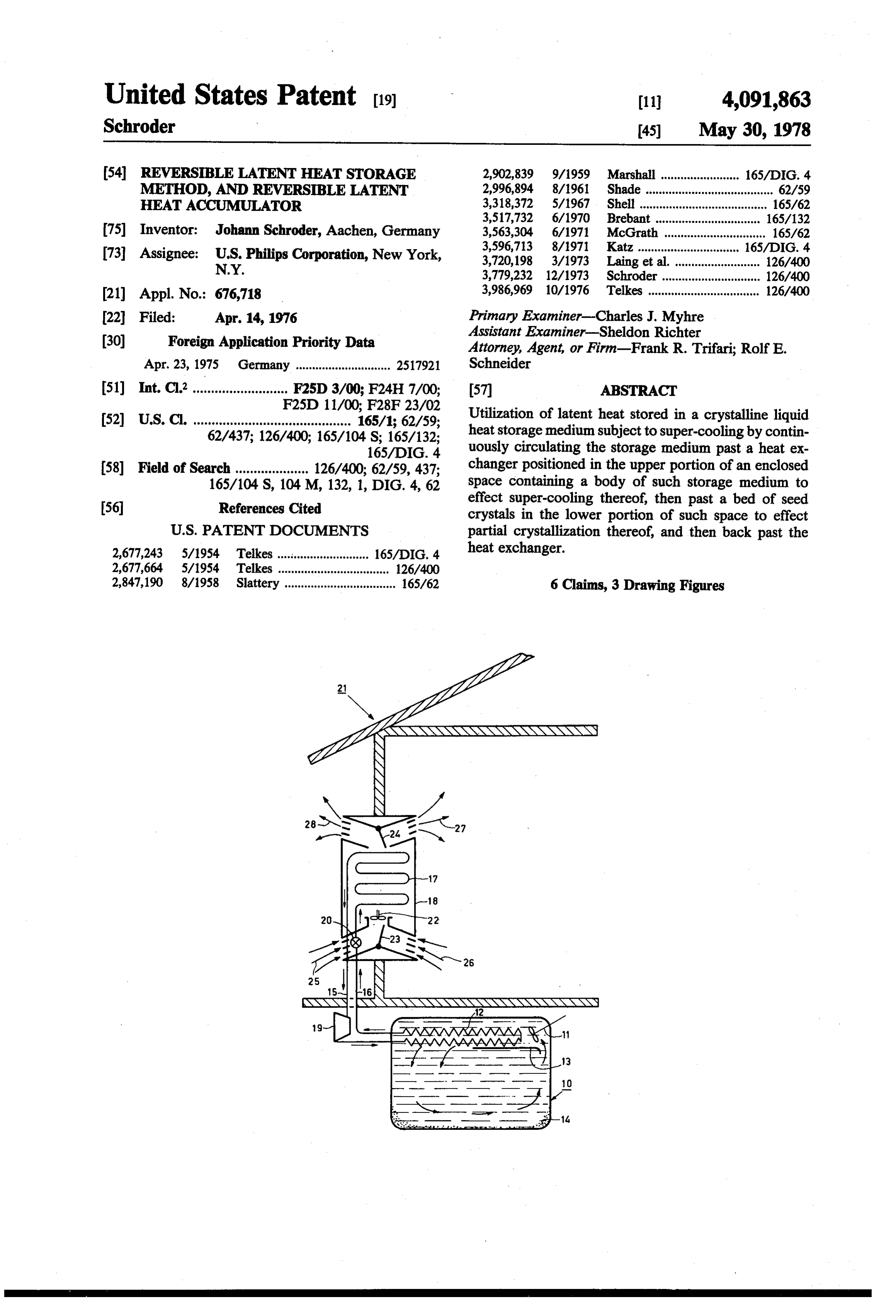
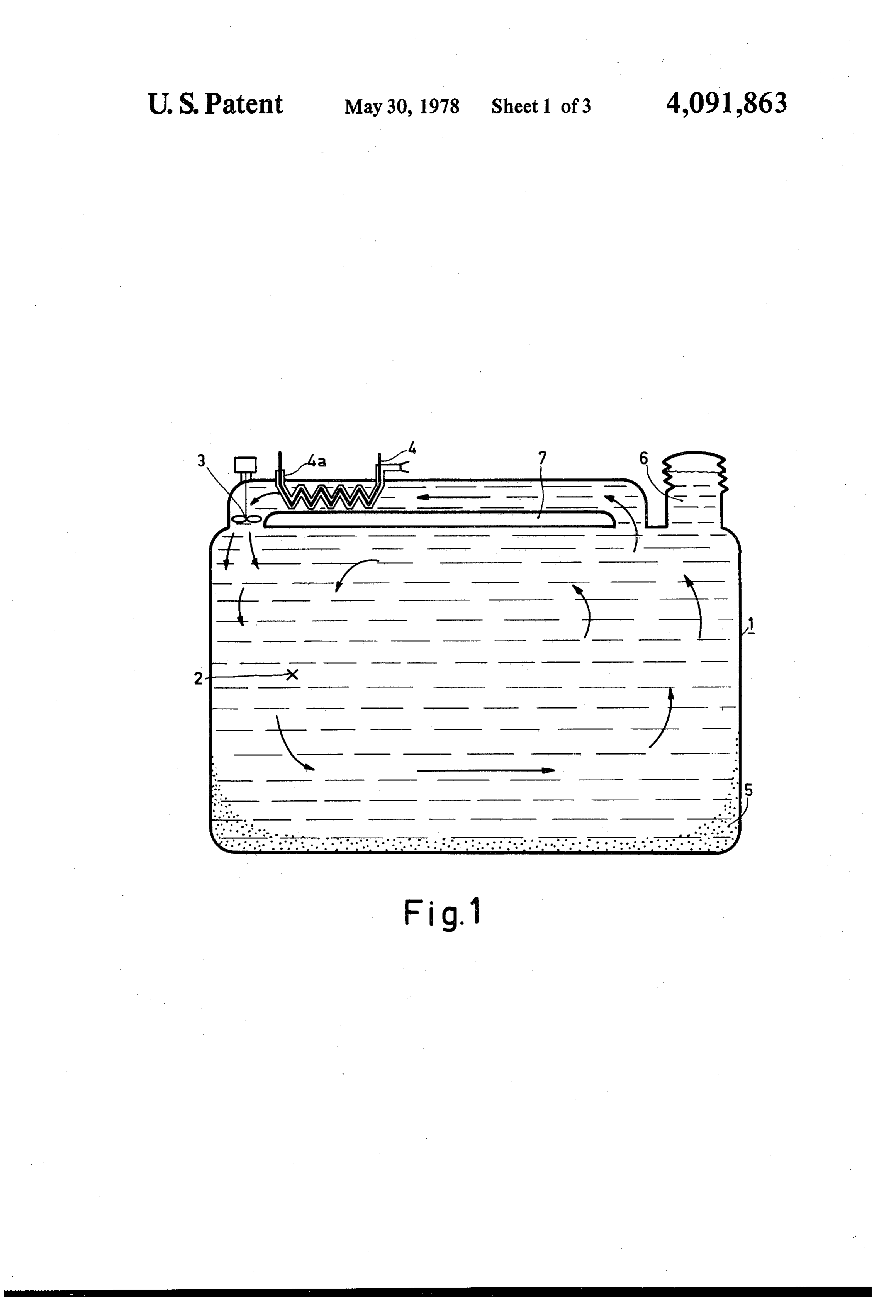
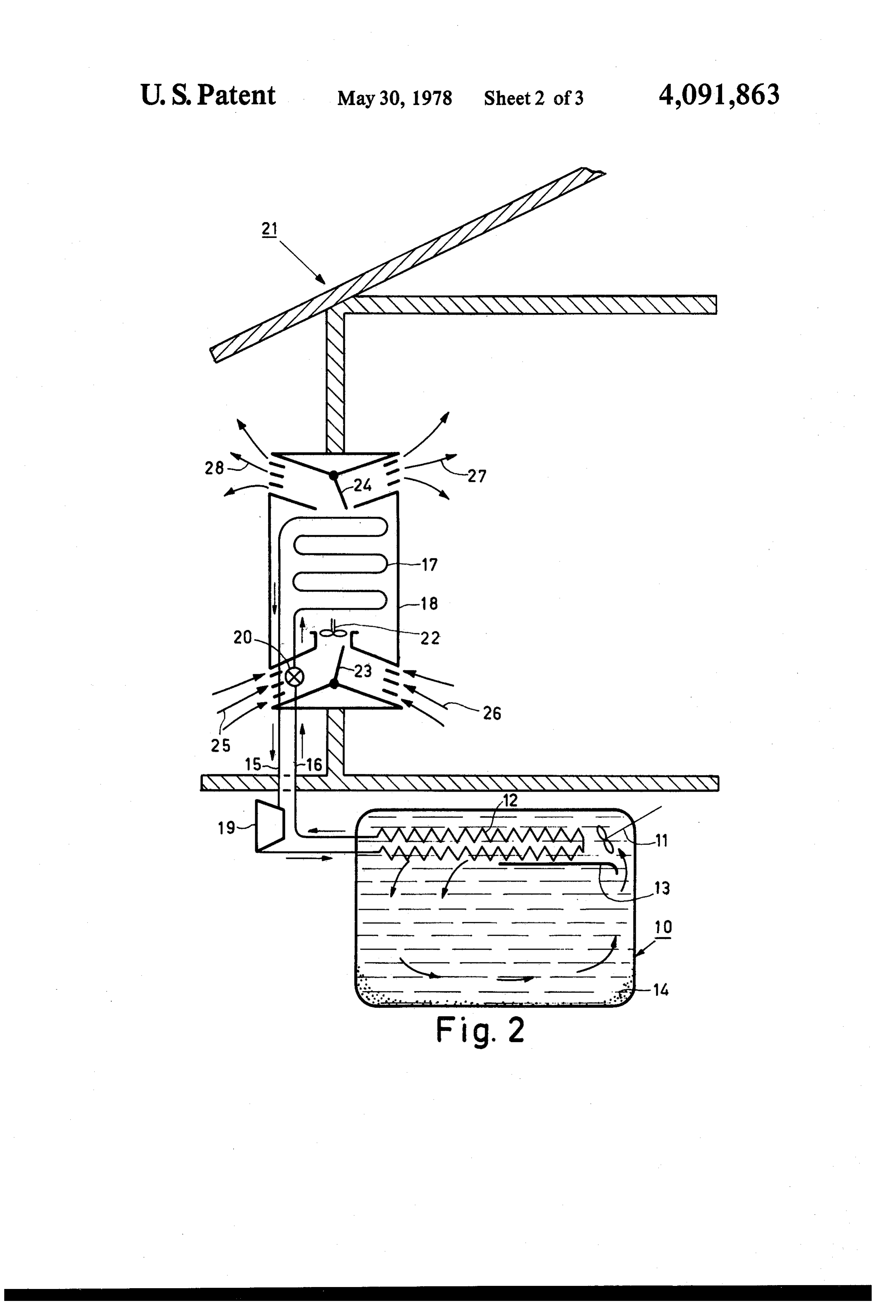
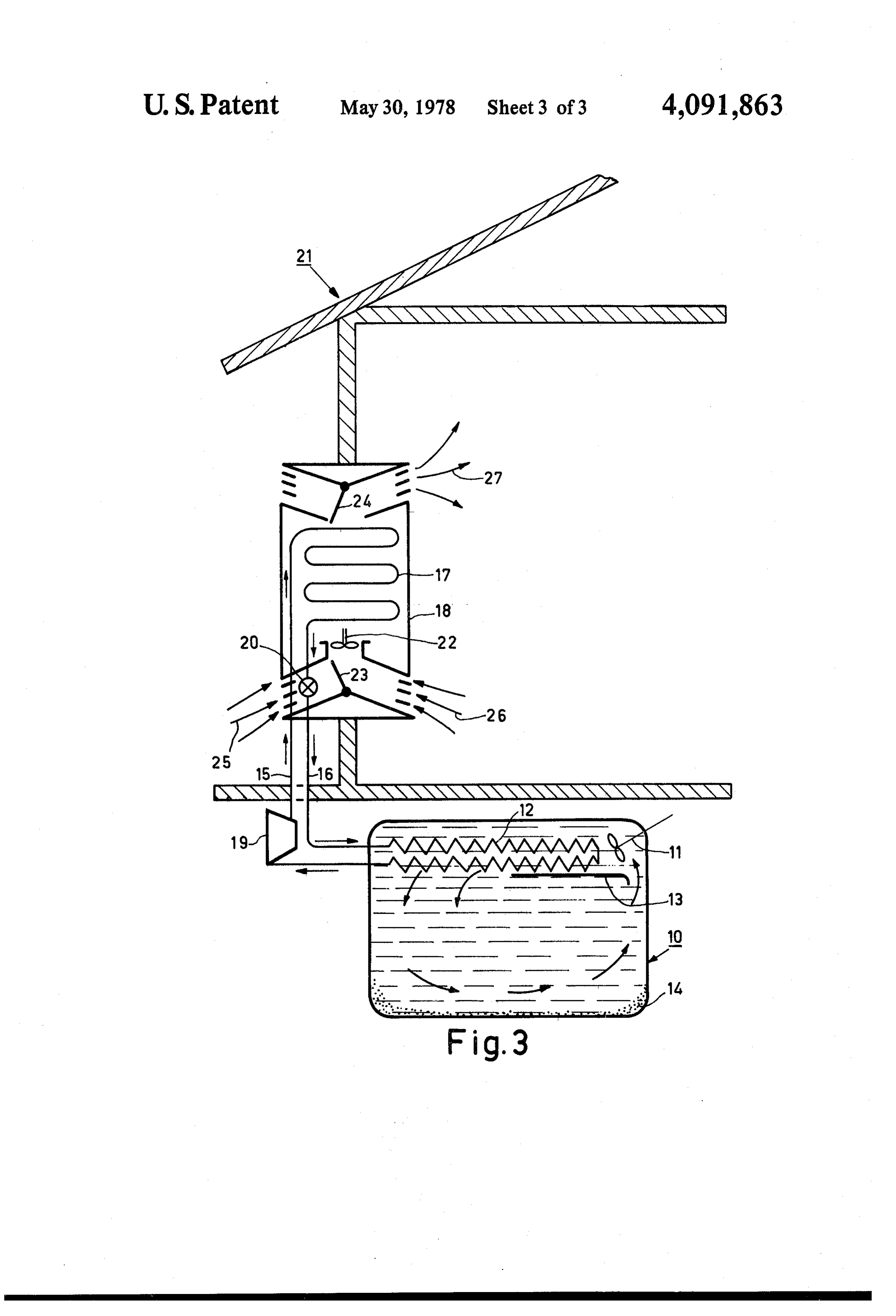
distributed over the entire volume of the heat storage 55 FIG. 1 is a longitudinal sectional view of an embodi medium. ment of the latent heat accumulator in accordance with The invention has for its object to provide a method the invention, and also illustrates the principle of the whereby heat can be applied to and extracted from the method in accordance with the invention. super-coolable heat storage medium in a simple manner. FIGS. 2 and 3 are longitudinal sectional views of a In order to achieve this object, the method according combination of an embodiment of the latent heat accu to the invention is characterized in that (i) the heat mulator in accordance with the invention and a heat storage medium is charged by being conducted past a pump for cooling or heating a house in summer (FIG.2) heat exchanger having a temperature above the melting and in winter (FIG. 3), respectively. point of the heat storage medium and (ii) is discharged The reference 1 in FIG. 1 denotes a closed reservoir by (a) the temperature of the heat exchanger being kept 65 containing a heat storage medium in the form of a salt at a sufficiently low value below this melting point and hydrate 2, for example, an aqueous solution of 44 to (b) the flow rate of the heat storage medium near the 48% by weight KF, a pumping device 3, and a heat heat exchanger being maintained at a sufficiently high exchanger 4. A small quantity of a crystal nucleating
Page 6
material 5 for the heat storage medium is provided on the fan 22. The ratio between these air flows is con the bottom and the side-walls of the reservoir. trolled by the valve 23. The air gives off heat to the heat The reservoir 1 furthermore includes a device 6 for exchanger 17 and flows as cool air 27 into the house 21 compensating for the pressure and the level of the heat and/or flows to the outside as cool air 28. The ratio storage medium. Guide faces 7 are also provided. between these air flows is controlled by the valve 24. Assuming that the accumulator has been charged, so A heat transport medium, for example, a fluorocar that the heat storage medium is in the liquid phase, the bon, heated in the heat exchanger 17, is sucked by the discharging is effected as follows. compressor 19 and is further heated by compression. The pumping device 3 conducts the liquid heat stor After the compression, the heat transport medium flows age medium past the heat exchanger 4, so that the heat 10 through the heat exchanger 12 while giving off heat to storage medium is cooled by the heat exchanger (for the accumulator 10. Subsequently, the pressure of the example, directly via the evaporator of a heat pump, heat transport medium is reduced in the expansion valve FIGS. 2 and 3). The melt 2 is cooled to a temperature 20 and, being a cold, low-pressure medium, it is heated which is only slightly (for example, approximately 5° C) again below its melting point. This method of cooling, in 15 FIG.in 3theshows heat exchanger 17. the operation in winter. Cold outside conjunction with a suitably chosen minimal flow rate of air 25 and/or lukewarm the heat storage medium passing the heat exchanger 4, 22 via the valve 23 and inside air 26 is drawn by the fan ensures that the nucleation and the crystallization ve medium in the heat exchanger 17.byThe is heated the heat transport locity of the heat storage medium are so small at the flows into the house 21. The valve 24 keepsheated the air 27 connec area of the heat exchanger 4 that no or almost no solid 20 tion with the outside atmosphere closed. phase is separated at this area. The supercooled heat storage medium is subsequently passed over the crystal tionTheandcompressor sucks the 19 now operates in the reverse direc heat transport medium which has nucleating material 5 while giving off the meltenthalpy.
The supercooling and the supersaturation of the passing been heated in the accumulator 10. After the compres melt 2 are eliminated at this area due to the crystalliza 25 sion, further increasing the temperature of the heat tion then occurring. Subsequently, the remaining meltis transport medium, this medium flows through the heat exchanger 17 whereby it is cooled. Subsequently, its again conducted, via the guide faces 7, past the heat pressure is reduced in the expansion valve 20, so that it exchanger 4. Following the initial crystallization by means of the crystal nucleating material 5, further crys is further cooled. Heat, from the accumulator, is then tallization can take place by the solidified heat storage 30 taken up again in the heat exchanger 12. Obviously, the heat exchanger 17 can also serve for medium then present at this area. Obviously, the heat heating water. It is alternatively possible to store solar accumulator may be discharged only to the extent that enough liquid heat storage medium is still present for energy in the accumulator, for example, by circulating heat exchange with the heat exchanger 4. Depending on the heat storage medium directly past or through a solar the dimensions and the construction of the accumulator, 35 energy collector.
only a very small quantity of heat storage medium is What is claimed is:
required for this purpose (1% or less). 1. A method of utilizing latent heat stored in a crystal Any crystal growth on the heat exchanger 4 after lizable liquid heat storage medium subject to super prolonged operation can be removed by periodically cooling, which comprises providing a body of said slightly inflating an envelope 4a of synthetic foil pro storage medium in an enclosed space associated with a vided on the heat exchanger 4 by means of a pump or heat exchanger and having a bed of seed crystals in the bellows, so that the crystals are loosened. It is alterna lower portion thereof, maintaining the heat exchanger tively possible to periodically operate the heat pump at a temperature below the melting point of the storage briefly in the opposite direction (FIGS. 2 and 3), so that medium, continuously circulating the storage medium the crystals are melted. Melting can also be achieved by 45 past the heat exchanger to effect super-cooling thereof electric heating. and past the seed crystal bed to effect partial crystalliza In the case of charging, the heat exchanger 4 has a tion thereof and back past the heat exchanger, and temperature which is higher than the melting point of maintaining the flow rate of the storage medium past the heat storage medium. The pumping device 3 again the heat exchanger at a sufficiently high value so that no provides the circulation of liquid heat storage medium 50 or substantially no crystallization of the storage medium past the heat exchanger 4 and subsequently past solidi occurs near the heat exchanger and no or substantially fied storage medium to be melted. no crystals are formed on the heat exchanger. The reference 10 in FIG. 2 denotes a latent heat accu 2. A method according to claim 1, in which the heat mulator in which a pumping device 11, a heat ex exchanger is positioned in the upper portion of said changer 12 and a flow guide partition 13 are arranged. 55 enclosed space.
On the bottom of the accumulator 10 there is provided 3. A method according to claim 1, in which the stor a small quantity of a crystal nucleating material 14 for age medium comprises an aqueous solution of 44 to 48% the heat storage medium, which can circulate in the by weight KF.
liquid phase in the accumulator 10 in the direction de 4. A method according to claim 1, in which the stor noted by the arrows. age medium comprises NaSO 10HO. The heat exchanger 12 communicates, via ducts 15 5. A method according to claim 1, in which the tem and 16, with a heat exchanger 17 in a housing 18. The perature of the heat exchanger is briefly raised above duct 15 includes a compressor 19 and the duct 16 in the melting point of the storage medium in the event of cludes an expansion valve 20. The reference 21 denotes crystal formation on the heat exchanger. the house to be cooled. 65 6. A method according to claim 5, in which the tem There are also provided a fan 22 and valves 23 and 24. perature of the heat exchanger is raised by reversal of a During operation in summer, hot or warm outside air heat pump includingit saidsk heat exchanger. 25 and/or warm air 26 from the house 21 is drawn by
Provenance
- Collection
- Cited prior art
- Original PDF
- patentimages.storage.googleapis.com →
- Filed
- 1976-04-14
- Pages
- 6
- Method
- pdftotext (the PDF's own text layer) + pdftoppm 300dpi page scans
- Source
- Google Patents bibliographic record
- Granted
- 1978-05-30
- Inventors
- Johann Schroder; US Philips Corp
- Transcribed from
- patentimages.storage.googleapis.com →