patent · US3330755
Electrolytic apparatus
11 July 1967
Page 1
Drawing sheet — no readable text.
Page 2
Drawing sheet — no readable text.
Page 3
United States Patent Office 3,330,755 Patented July 11, 1967
3,330,755 tank of apparatus built according to a presently preferred EECTROLYTIC APPARATUS embodiment of the invention;
William J. Mahany, Camandaigua, N.Y. assignor to Elec FIG. 2 is a horizontal sectional view taken along the fro-Ceil Corporation, Canandaigua, N.Y., a corporation of New York line 2-2 of FIG. 1, looking in the direction of the ar rows;
Filed Aig. 14, 1962, Ser. No. 216,799 FIG. 3 is a schematic diagram of the hydraulic and 3 Clainias. (CH. 204—230) pneumatic circuits of the apparatus;
This invention relates to novel apparatus for produc FIG. 4 is a vertical sectional view of the pressure dif ing gases by electrolytic decomposition of a liquid, and O ferential sensing device, which is incorporated in the ap more particularly to apparatus for producing oxygen and paratus as shown in FIG. 3; and FIG. 5 is an electrical schematic diagram of the elec hydrogen by the electrolytic decomposition of water. In a still more specific aspect the invention relates to novel ap trical operating and control portion of the apparatus. Briefly, the apparatus of the present invention includes paratus of this type which is of relatively compact and a pressure tank for containing an electrolytically decom portable construction and especially suitable for econom 5 posable liquid, such as water, a pump for feeding the ical use in applications where only relatively small quan liquid into the tank, accumulators for storing the gases tities of gases are required.
Previously known electrolytic apparatus for producing produced by electrolysis in the tank, pressure equalization means for preventing the buildup of a pressure differential oxygen and hydrogen have been relatively bulky, and between the two accumulators, and a relatively simple sys complex both in construction and operation. Accordingly, 20 tem of automatic controls to achieve fully automatic, fail they have not been suitable for point-of-use installation, especially in applications where only relatively small quan safeTheoperation of the apparatus. pressure equalization means includes a pair of elec tities of the gases are desired. Most small consumers of trical probe chambers connected respectively to the anodic oxygen and hydrogen have heretofore preferred to buy and cathodic gas output sides of the electrolyzer tank, the gases in pressure cylinders and to replace the cylin and through a flow-restrictive device to each other. The ders as they become empty. Such cylinders are, however, chambers are partly filled with an electrically conductive heavy and difficult to handle. They are, moreover, diffi liquid, and a probe extends downwardly within each cham cult to store and are a safety hazard. Furthermore, the ber for contacting the liquid whenever it is above a pre consumer has to pay not only for the gas used, but for the cost of compressing the gas so that it can be packed 30 determined differential level therein. Even a relatively small pressure between the outputs of the electrolyzer drives in a cylinder, for the handling of the cylinder, of storing the liquid downwardly in one chamber below the lower it before and after use, and of returning it when empty. end of the probe in that chamber, thereby breaking an One important object of the present invention is to electrical circuit to produce an electrical signal in re provide novel, economical electrolytic apparatus for pro sponse to the pressure differential. The sensor is ex ducing gases such as hydrogen and oxygen, and more par tremely sensitive, yet fully reliable and dependable in op ticularly to provide apparatus of this type which is es eration. Means responsive to the sensor are provided for pecially suitable for point-of-use installation in situations venting the relatively higher pressure output of the elec where only moderate, or small quantities of the gases are trolyzer, thus to limit the pressure differential to a rela required.
Another object of the invention is to provide apparatus 40 tively small value.
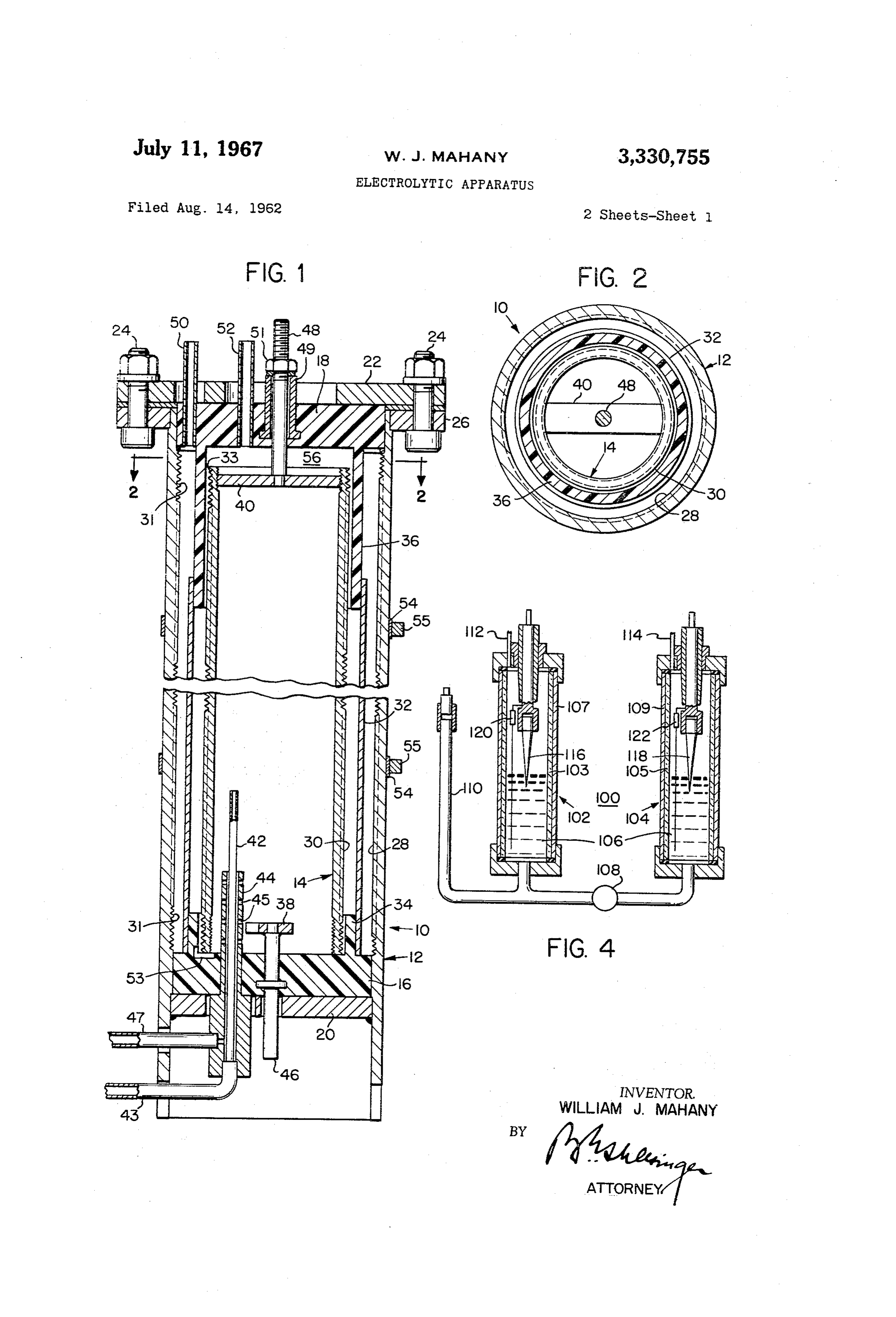
Referring now to the drawings, and first to FIG. 1, the of the character described which is capable of fully auto apparatus shown includes an electrolyzing tank, or gen matic operation, producing hydrogen and oxygen on de erator unit 10 comprising an outer steel tube or cylinder mand as required.
Another object is to provide apparatus of this type and 12 and an inner steel tube or cylinder 14. The tubes 12 which is fully automatic, yet of relatively simple and in tively, 14 function as the cathode and the anode, respec expensive construction, highly dependable, and trouble should be of the electrolyzer unit. The walls of these tubes free and long-lasting in service. of equal thickness. A further object of the invention is to provide apparatus The opposite ends of the outer tube or cylinder 12 are of the character described which includes a relatively sim 50 closed by plastic insulating plates, or discs 16 and 18, respectively, which seal against the inner wall of the tube.
ple and trouble-free pressure balancing system to keep The lower disc 16 is supported by a lower reinforcing the oxygen and hydrogen under equal pressures, thereby to prevent inadvertent mixing of the two gases within the plate 20, which may be made of steel molded to the electrolyzer and to insure continuous trouble-free opera secureddisc plastic 16 and which is welded, or otherwise rigidly within the outer tube or cylinder 12 near the tion.
lower end thereof. The upper insulating disc 18 is re
Another object is to produce apparatus of this type 55 tained in place by a steel cover plate 22, which is mold which includes a novel, highly sensitive, pressure differ ed to plastic disc 18 and which is removably secured to ential sensor for detecting a pressure differential between the outer tube 12 by bolts 24, as shown, or by any other the cathodic and the anodic outputs of the electrolyzer, desired means. The bolts 24 extend through the cover and automatic means responsive to the sensor for limit 60 plate 22 and through a flange 26, which is welded to ing any such pressure differential to relatively small val and extends exteriorly around the outer tube or cylin S. der 12 at the upper end thereof.
Still another object of the invention is to provide ap The inner surface 28 of the outer tube 12 and the paratus of the character described which is readily trans outer surface 30 of the inner tube 14 are preferably portable, but which, if desired, may be placed in a cen threaded for their full heights, as shown at 31 and 33 and their threaded portions are preferably rough sand tral location and its output piped to utilization points. 'blasted or otherwise corrugated or striated in order to The foregoing and other objects and advantages of the increase their effective areas. The threads are prefer invention will become apparent from the following de ably tailed description of a representative embodiment thereof, 70 A porous,plated nickel for greater conductivity.
tubular separator or diaphragm 32, which taken in conjunction with the drawing, wherein:
FIG. 1 is a vertical sectional view of the electrolyzing ismaysupported be, for example, of woven asbestos and preshrunk, between the outer tube 12 and the inner
Page 4
3 The surface level of the electrolyte is kept above the tube 14 upon annular, axially extending collars 34 and lower edge of the upper flange or collar 36 so that the 36, respectively, which are integral with the respective flange or collar 36 acts to seal the oxygen and hydrogen end plates 16 and 18. The inner tube 14 fits loosely inside apart in their two separate outlet regions. Any pressure the collars 34 and 36; and there is adequate clearance differential that may develop between the oxygen and between the inner tube 14 and the upper collar 36 to hydrogen outlet regions is controlled by means to be permit gases generated during electrolysis to pass freely described hereinafter so that the electrolyte remains above between this inner tube 14 and the upper collar 36. the lower edge of the flange or collar 36 on both sides A pair of coaxially arranged tubular ducts 42 and 44 of the flange.
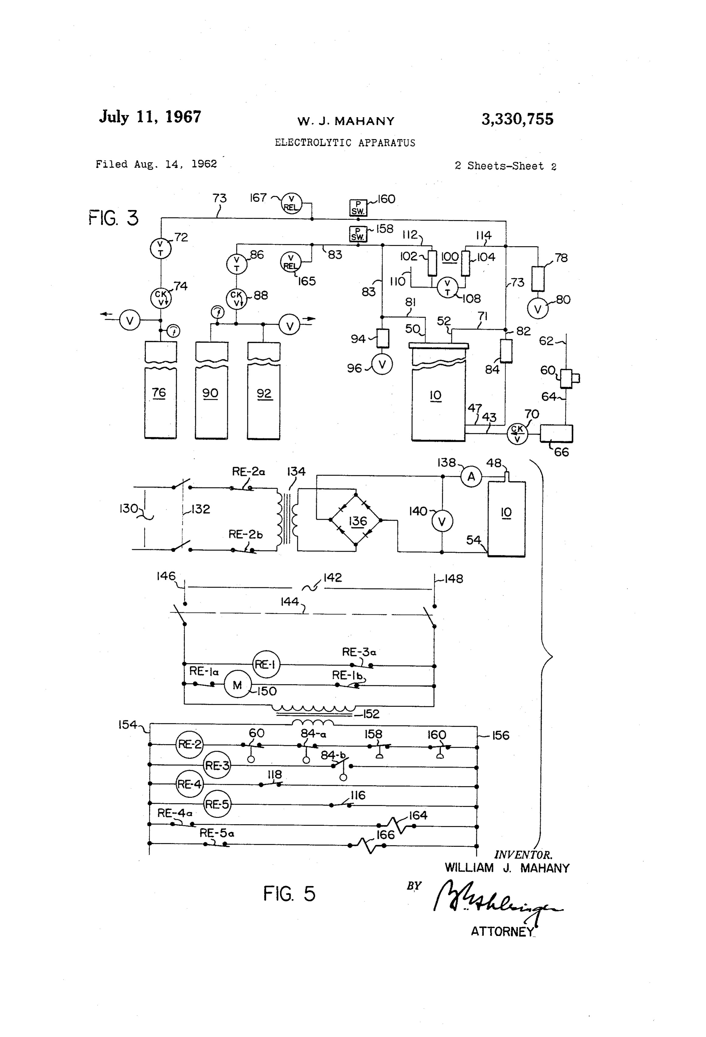
are sealed through the lower insulating disc 16. The inner The hydraulic and pneumatic connections for the ap duct 42 is connected to a pipe 43 and serves as the liquid O paratus are shown in FIG. 3. Water is supplied through inlet to conduct water into the generator unit. The outer an inlet 62 which is preferably connected to a supply of tube 44 is of larger bore diameter than the outside diam preferably distilled water. This supply line is connected eter of tube 42 so that there is space between it and the outside of tube 42. It is provided with a plurality of ports 5 through 64 which a float-operated safety switch 60 to the pipe is connected to a pump 66. The float-operated 45 and serves to connect the electrolyzer through a pipe safety cut-off switch 60 is included for cutting off opera 47 to a liquid level sensor and indicator 84 (FIG. 3). tion of the apparatus in the event of failure of the water The reinforcing plate 20 is apertured to provide clear supply. The outlet of the pump 66 is connected through ance for the duct 44 without making electrical contact a check valve 70 to the inlet 43 of the electrolyzer unit 10. with it. 20 The anodic outlet 52 of the electrolyzer unit is con Electrically conductive plates or straps 38 and 40, re nected through piping 71, 73, a flow control valve 72, spectively, are threaded into the opposite ends of the and a check valve 74 to an oxygen storage tank 76. A inner, anode tube 14, or otherwise conductively secured trap 78 and a drain valve 80 are also connected to the thereto, to effect a relatively low resistance electrical Con anode outlet 52 for removing moisture and other im nection to it. The plates 38 and 40 are welded, or other wise conductively secured to relatively heavy electrical purities from the oxygen. The anodic outlet 52 is also leads or terminals 46 and 48, respectively, which are sealed connected by piping 82 to the upper end of a double throw, liquid-level operated switch 84, the lower end of through the lower and upper insulating plates 16 and which is connected to the inlet 47 at the bottom of the 18, respectively, and which serve as electrical input ter electrolyzer 10. The float-operated switch 84 controls the minals for the inner cylinder 14. A tubular steel insert 30 energization of the pump motor 66 to maintain the de 49, which is molded into the plastic disc 18, and a nut sired level of the electrolyte within the electrolyzer unit 51 which is threaded on the upper anode terminal 48, 0.
serve to secure this terminal in place. The cathodic outlet 50 is connected through piping The upper annular collar 36 is spaced inwardly from 81, 83, a flow control valve 86, and a check valve 88 the outer tube 12 to allow gas generated during elec to storage tanks 90 and 92. As shown, twice the storage trolysis to pass upwardly between the collar 36 and the capacity is provided for the cathode output (hydrogen) tube 12. - as for the anode output (oxygen). The relative capacities A first outlet pipe 50 is molded into and sealed through of the storage tanks 76, 90 and 92 would normally be the upper insulating plate 18 and opens interiorly in the selected on the basis of the expected demand for each annular space between the upper annular collar 36 and 40 particular installation. In those installations wherein it the outer tube 12. A second outlet pipe 52 is also molded is desired to provide primarily oxygen and relatively little into and sealed through the upper insulating plate 18 hydrogen, or no hydrogen, the oxygen storage tank 76 and opens interiorly within the annular collar 36. is preferably made relatively large, and the hydrogen For operation, a solution of sodium, potassium or lith storage tanks 90 and 92 may be replaced by a relatively ium hydroxide or other highly conductive liquid is placed small accumulator, or ballast tank (not shown) which within the electrolyzer unit 10, and water is admitted 45 would serve primarily to reduce undesired, sudden pres through the inlet 42 filling the inner and outer cylinders sure changes in the system. A trap 94 and a drain valve 14 and 12 to a height determined by the liquid level 96 are also connected to the cathode outlet 59 to remove sensor and indicator 84 (FIG. 3). The water flows from water vapor and other impurities that may be carried by cylinder 14 into cylinder 12 through the groove 53 in 50 the cathode gas out of the electrolyzer 10. plate 16 and through the porous baffle 32. The groove 53 A pressure differential sensor 100 is connected between extends under the lower end of tube 14. Instead of a the anode and cathode outlets 52 and 50, respectively, groove, holes may be provided in the lower end of tube for detecting pressure differences between the cathode 14. Lithium hydroxide will minimize foaming. The ter and anode gases in the electrolyzer.
minals 46 and 48 of the inner cylinder are connected to 55 As shown in detail in FIG. 4, the sensor 100 includes the anode of a battery or other source of unidirectional a pair of sealed vessels 102 and 104, which are partially electric current, and the outer cylinder 12 is connected to filled with a conductive fluid 106 and are connected to the cathode. Electrical connections to the outer tube 12 gether at their lower ends through a flow restrictive may be made by means of conductive bands or straps needle valve 108, or any other desired flow restrictive 54 tightened around this tube at axially spaced intervals 60 device. A fill pipe 110 is connected to the lower ends therealong and connected by jumpers to the terminal fluid of the vessels 102 and 104 for introducing the conductive cathode connectors 55. 106 into them. This tube is normally stoppered The water of the electrolyte is decomposed by the cur during operation. Gas inlet tubes 112 and 114, which rent flowing between the outer cylinder 12 and the inner are connected through tubing 83, 73, respectively, to the cylinder 14, forming oxygen, and hydrogen. The oxygen 65 respective outlets 50 and 52 of the electrolyzer 10, are flows upwardly along the outer surface of the inner cylin Sealed
through the upper ends of the vessels 102 and der 14 into the region 56 within the upper annular flange 36 and exhausts through the inner outlet nipple 52. The letsA 50differential
in gas pressure at the electrolyzer out thus causes a corresponding differential hydrogen forms along the inner surface 28 of the outer cylinder and flows upwardly therealong into the space 70 in the levels of the electrolyte 106 in the respective vessels 102 and 104. When there is no pressure differential, that between the outer cylinder 12 and the annular flange or is, when the pressure within the electrolyzer 10 is the collar 36 and exhausts through the outer outlet nipple same at the anode outlet 52 as at the cathode outlet 50, 50. The nipples are connected by piping to the respective the electrolyte 106 stands at the same level in both of oxygen and hydrogen storage tanks where the gases are the vessels 102 and 104.
available for use. 5
Page 5
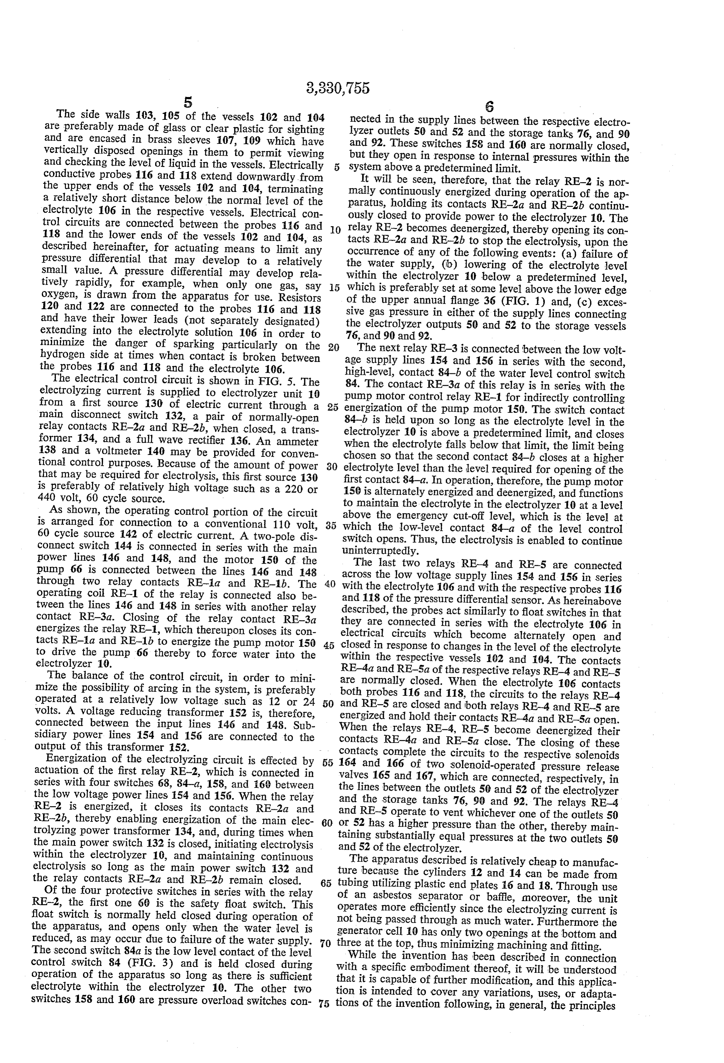
The side walls 103, 105 of the vessels 102 and 104 nected in the supply lines between the respective electro are preferably made of glass or clear plastic for sighting lyzer outlets 50 and 52 and the storage tanks 76, and 90 and are encased in brass sleeves 107, 109 which have and 92. These switches 158 and 160 are normally closed, vertically disposed openings in them to permit viewing but they open in response to internal pressures within the and checking the level of liquid in the vessels. Electrically system above a predetermined limit. conductive probes 116 and 118 extend downwardly from It will be seen, therefore, that the relay RE-2 is nor the upper ends of the vessels 102 and 104, terminating mally continuously energized during operation of the ap a relatively short distance below the normal level of the electrolyte 106 in the respective vessels. Electrical con paratus, ously holding its contacts RE-2a and RE-2b continu closed to provide power to the electrolyzer 10. The trol circuits are connected between the probes 116 and relay RE-2 becomes deemergized, thereby opening its con 118 and the lower ends of the vessels 102 and 104, as tacts RE-2a and RE-2b to stop the electrolysis, upon the described hereinafter, for actuating means to limit any occurrence of any of the following events: (a) failure of pressure differential that may develop to a relatively the water supply, (b) lowering of the electrolyte level small value. A pressure differential may develop rela within the electrolyzer tively rapidly, for example, when only one gas, say 15 which is preferably set at10some below a predetermined level, level above the lower edge oxygen, is drawn from the apparatus for use. Resistors of the upper annual flange 36 (FIG. 1) and, (c) exces 120 and 122 are connected to the probes 116 and 118 sive gas pressure in either of the supply lines connecting and have their lower leads (not separately designated) the electrolyzer outputs 50 and 52 to the storage vessels extending into the electrolyte solution 106 in order to minimize the danger of sparking particularly on the 20 76,The and 90 and 92.
next relay RE-3 is connected between the low volt hydrogen side at times when contact is broken between age supply lines 154 and 156 in series with the second, the probes 116 and 118 and the electrolyte 106. high-level, contact 84-b of the water level control switch The electrical control circuit is shown in FIG. 5. The 84. The contact RE-3a of this relay is in series with the electrolyzing current is supplied to electrolyzer unit 10 pump motor control relay RE-1 for indirectly controlling from a first source 130 of electric current through a 25 energization of the pump motor 150. The switch contact main disconnect switch 132, a pair of normally-open relay contacts RE-2a and RE-2b, when closed, a trans electrolyzer 10upon 84-b is held so long as the electrolyte level in the is above a predetermined limit, and closes former 134, and a full wave rectifier 136. An ammeter when the electrolyte falls below that limit, the limit being 138 and a voltmeter 140 may be provided for conven chosen so that the second contact 84-b closes at a higher tional control purposes. Because of the amount of power 30 electrolyte level than the level required for opening of the that may be required for electrolysis, this first source 130 first contact 84-a. In operation, therefore, the pump motor is preferably of relatively high voltage such as a 220 or 150 is alternately energized and deemergized, and functions 440 volt, 60 cycle source. to maintain the electrolyte in the electrolyzer 10 at a level As shown, the operating control portion of the circuit is arranged for connection to a conventional 110 volt, 35 which the above emergency cut-off level, which is the level at the low-level contact 84-a of the level control 60 cycle source 142 of electric current. A two-pole dis switch opens. Thus, the electrolysis is enabled to continue connect switch 144 is connected in series with the main uninterruptedly.
power lines 146 and 148, and the motor 150 of the The last two relays RE-4 and RE-5 are connected pump 66 is connected between the lines 146 and 148 through two relay contacts RE-1a and RE-1b. The with thetheelectrolyte across low voltage supply lines 154 and 156 in series 106 and with the respective probes 116 operating coil RE-1 of the relay is connected also be and 118 of the pressure differential sensor. As hereinabove tween the lines i46 and 148 in series with another relay described, the probes act similarly to float switches in that contact RE-3a. Closing of the relay contact RE-3a they are connected in series with the electrolyte 106 in energizes the relay RE-1, which thereupon closes its con electrical circuits which become alternately open and tacts RE-1a and RE-1b to energize the pump motor 150 45 closed in response to changes in the level of the electrolyte to drive the pump 66 thereby to force water into the within the respective vessels 102 and 104. The contacts electrolyzer 10. RE-4a and RE-5a of the respective relays RE-4 and RE-5 The balance of the control circuit, in order to mini are normally closed. When mize the possibility of arcing in the system, is preferably both probes 116 and 118, thethecircuits electrolyte 106 contacts to the relays RE-4 operated at a relatively low voltage such as 12 or 24 50 and volts. A voltage reducing transformer 152 is, therefore, energized and hold their contacts RE-4a andand RE-5 are closed and both relays RE-4 RE-5 are
RE-5a open.
connected between the input lines 46 and 148. Sub sidiary power lines 154 and 156 are connected to the When the relays RE-4, RE-5 become deemergized their contacts RE-4a and RE-5a close. The closing of these output of this transformer 152. contacts complete the circuits to the respective solenoids Energization of the electrolyzing circuit is effected by 55 164 actuation of the first relay RE-2, which is connected in valvesand165166 of two solenoid-operated pressure release and 167, which are connected, respectively, in series with four switches 68, 84-a, 158, and 60 between the low voltage power lines 154 and 156. When the relay the and lines between the outlets 50 and 52 of the electrolyzer the storage tanks 76, 90 and 92. The relays RE-4
RE-2 is energized, it closes its contacts RE-2a and and RE-5
RE-2b, thereby enabling energization of the main elec 60 or 52 has aoperate to vent whichever one of the outlets 50 higher pressure than the other, thereby main trolyzing power transformer 134, and, during times when taining substantially equal pressures at the two outlets 50 the main power switch 132 is closed, initiating electrolysis and 52 of the electrolyzer.
within the electrolyzer 10, and maintaining continuous electrolysis so long as the main power switch 132 and tureThebecause apparatus described is relatively cheap to manufac the relay contacts RE-2a and RE-2b remain closed. 65 tubing utilizingtheplastic cylinders 12 and 14 can be made from end plates 16 and 18. Through use
Of the four protective switches in series with the relay
RE-2, the first one 69 is the safety float switch. This of an asbestos separator or baffle, moreover, the unit operates more efficiently since the electrolyzing current is float switch is normally held closed during operation of not being passed through as much water. Furthermore the the apparatus, and opens only when the water level is generator reduced, as may occur due to failure of the water supply. three at thecelltop,10thus has only two openings at the bottom and minimizing machining and fitting.
The second switch 84a is the low level contact of the level While the invention has been described in connection control switch 84 (FIG. 3) and is held closed during with a specific embodiment thereof, it will be understood operation of the apparatus so long as there is Sufficient that it is capable of further modification, and this applica electrolyte within the electrolyzer 10. The other two tion switches 158 and 160 are pressure overload switches con 75 tionsisofintended to cover any variations, uses, or adapta the invention following, in general, the principles
Page 6
7 electrical signals in response to a pressure differential of the invention and including such departures from the in said electrolyzer between said outlets, one of said present disclosure as come within known or customary two signals indicating a relatively higher pressure at practice in the art to which the invention pertains and as one of said outlets, and the other of said two signals may be applied to the essential features hereinbefore set indicating a relatively higher pressure at the other forth, and as fall within the scope of the invention or the outlet, limits of the appended claims. (k) means responsive to said sensor for selectively Having thus described my invention, what I claim is: venting said outlets thereby to reduce such pressure 1. A compact gas generating apparatus comprising (a) an electrolyzer having an inlet for admitting a differential, (l) and a liquid level sensing device for alternately liquid, which is to be electrolytically decomposed, and O energizing and deemergizing said pump in response to two outlets for releasing, respectively, anodic and variations of liquid level within said electrolyzer, cathodic gaseous decomposition products of the liq thereby to maintain the liquid level within predeter
and equalization means for equalizing the gas mined limits.
3. A compact gas generating apparatus comprising pressures in said electrolyzer at said outlets, said pres ?5 (a) an electrolyzer having an inlet for admitting a liq mined limits. uid, which is to be electrolytically decomposed, and (c) a first vessel connected to one of said outlets, two outlets for releasing, respectively, anodic and (d) a second vessel connected to the other one of said cathodic gaseous decomposition products of the liq outlets, (e) means including a flow restrictive device connect 20 ing said second vessel to said first vessel, (b)uid,pressure and equalization means for equalizing the gas (f) an electrically conductive liquid partly filling both pressures in said electrolyzer at said outlets, said of said vessels, and pressure equalization means including (g) electrical probes extending downwardly within said (c) a first vessel connected to one of said outlets, vessels toward said liquid, whereby a relatively slight 25 (d) a second vessel connected to the other one of said differential between the pressures within said electro outlets, lyzer at said outlets will effect a differential in liquid (e) fluid conducting means connecting said second ves level within said vessels so that the probe in one of sel to said first vessel, said vessels contacts the liquid therein and the probe (f) an electrically conductive liquid partly filling both in the other one of said vessels is out of contact with the liquid therein,
g)of electrical said vessels, and probes extending downwardly within said (h) solenoid actuated vent valves connected respective vessels toward said liquid, whereby a relatively slight differential between the pressures within said electro ly to said outlets, and lyzer at said outlets will effect a differential in liquid (i) electrical circuit means for selectively energizing 35 level within said vessels so that the probe in one of said vent valves in response to the making of contacts said vessels contacts the liquid therein and the probe between said probes and said liquid thereby to vent in the other one of said vessels is out of contact with the one of said outlets at which the pressure in Said electrolyzer is relatively higher. the liquid therein, 2. A compact gas generating apparatus suitable for easy 40 (h) solenoid actuated vent valves connected respec portability comprising tively to said outlets, and (a) an electrolyzer having an inlet for admitting a liq (i) electrical circuit means for selectively energizing uid, which is to be electrolytically decomposed into said vent valves in response to the making of contacts constituent gases, and two gas outlets, said electro between said probes and said liquid thereby to vent lyzer including the one of said outlets at which the pressure in said (b) a pair of normally vertical, coaxially arranged, 45 electrolyzer is relatively higher. electrically conductive tubes, insulating end plates References Cited sealed to the outer one of said tubes and supporting
UNITED STATES PATENTS
(c)thea inner porousonecylindrical thereof, and diaphragm supported by said 50 1,322,417 11/1919 Fischer ------------- 204?260 end plates between said tubes, 1819,917 8/1931 Niederreither et al. -- 204–129 (d) said outlets opening within said outer tube on op 1842,703 1/1932 Vorce –––––––––––––– 204-260 posite respective sides of said diaphragm, 1,856,663 5/1932 Smith ----------- 204-280 X (e) inlet means opening within said inner tube near the 2,349,998 5/1944 "TriniulS ------------------- 204-260 lower end thereof for admitting a liquid to be elec 55 2,393,201 1/1946 Stafford ------------ 200-81.6 trolyzed, 2,470,073 5/1949 Low --------------- 204—266 (f) means for supplying liquid to be electrolyzed, 2,520,624 8/1950 Davey ----------- 200-81.6 X (g) a pump for forcing liquid from said supply means 2,695,874 11/1954 Zdansky ------------ 204?258 into said electrolyzer under pressure, 2,825,781 3/1958 Mitchell ----------- 20081.5-? (h) a liquid-level actuated switch for controlling opera 60 2,846,384 8/1958 Denora ----------- 204-266, X tion of said pump, (i) gas storage containers connected separately to said JOHN H. MACK, Primary Examiner.
outlets for storing the gaseous decomposition prod ucts of the liquid electrolyzed in said electrolyzer, HOWARDS. WILLIAMS, Examiner.
a pressure differential sensor connected between 5 A. B. CURTIS, W. VAN SISE, Assistant Examiners. outlets for selectively producing one of two 6
Provenance
- Collection
- Cited prior art
- Original PDF
- patentimages.storage.googleapis.com →
- Filed
- 1962-08-14
- Pages
- 6
- Method
- pdftotext (the PDF's own text layer) + pdftoppm 300dpi page scans
- Source
- Google Patents bibliographic record
- Granted
- 1967-07-11
- Inventors
- William J Mahany; Electro-Cell Corp
- Transcribed from
- patentimages.storage.googleapis.com →