patent · US5603290
Hydrogen engine and combustion control process
18 February 1997
Page 1 — bibliographic record
III III III
United States Patent 19) 11 Patent Number: 5,603,290 Swain et al. (45) Date of Patent: Feb. 18, 1997 (54) HYDROGEN ENGINE AND COMBUSTION 3,471,274 10/1969 Quigley, Jr. et al. .................. 48/180.1 CONTROL PROCESS 3,616,779 11/1971 Newkirk ............................... 123f41.86 3,949,719 4/1976 Bellanca et al. ..................... 23/418.6 (75) Inventors: Michael R. Swain, Coral Gables; 4,557,226 12/1985 Mayer et al. ........................... 1231572 Matthew N. Swain, Miami, both of 4,616,620 10/1986 Paoluccio ............................. 123/4186 Fla. 4,656,991 4/1987 Fukuo et al. . ... 23/41.86 4,721,090 1/1988 Kato ........................................ 123,572 (73) Assignee: The University of Miami, Miami, Fla. 5,231,954 8/1993 Stowe .......................................... 123/3
OTHER PUBLICATIONS
21 Appl. No.: 528,814 Copy of excerpt from Acura Integra Service Manual Jan. (22 Filed: Sep. 15, 1995 1987.
51 Int. Cl. ............... F02M 25/06 Primary Examiner-David A. Okonsky 52 U.S. Cl. ........................................ 123/41.86; 123/572 Attorney, Agent, or Firm-Austin R. Miller (58 Field of Search ................................. 123/41.86,572, (57) ABSTRACT
Hydrogen engine with controlled combustion comprises (56) References Cited suction means connected to the crankcase reducing or pre
combustion chamber.
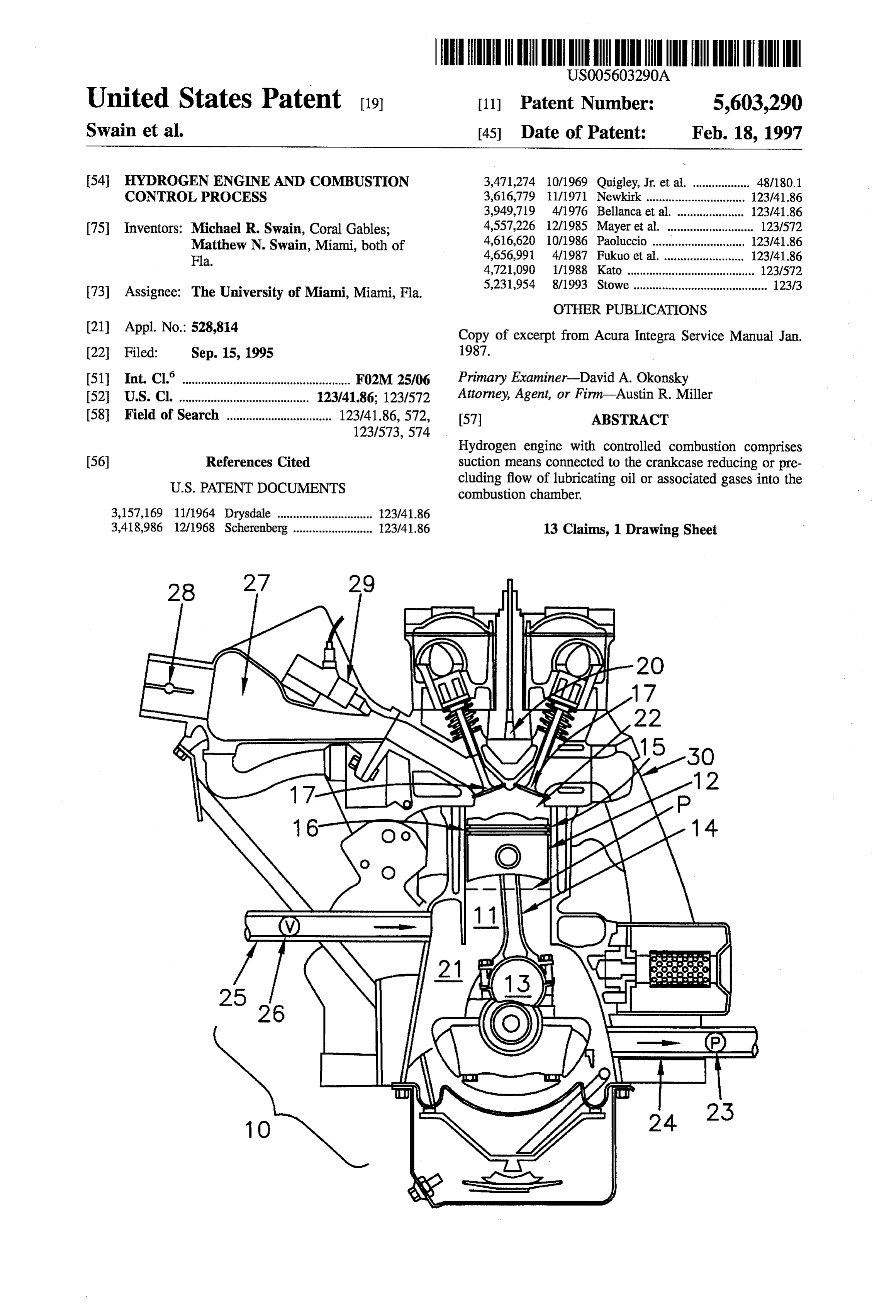
3,157,169 11/1964 Drysdale .............................. 123/41.86 3,418,986 12/1968 Scherenberg ......................... 123/41.86 13 Claims, 1 Drawing Sheet
Page 2
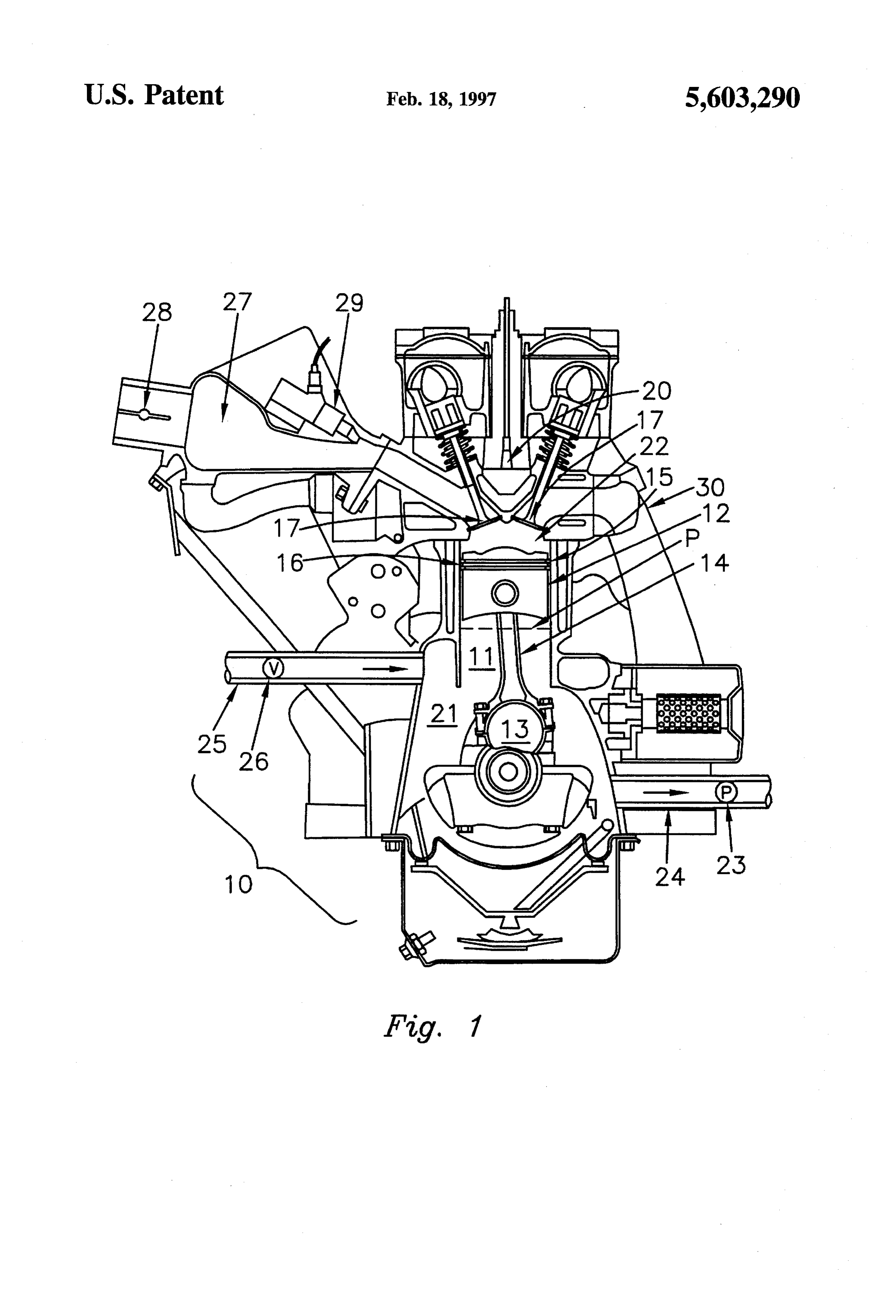
Drawing sheet — no readable text.
Page 3
HYDROGEN ENGINE AND COMBUSTION SUMMARY OF THE INVENTION
CONTROL PROCESS
We have discovered that a major source of engine flash back surprisingly comprises leakage or seepage of engine
GOVERNMENT RIGHTS lubricants and associated gases into the hydrogen combus tion chamber, and that great advantage is gained by reducing
The Government has rights in this invention pursuant to the flow of oil and gases from the piston ring crevice a contract awarded by the U.S. Department of Energy. This volumes into the combustion chamber. We have discovered invention may be manufactured, used and licensed by or for that this can be achieved by forcibly reducing the ambient the Government for governmental purposes without pay O pressure in the engine crankcase. This is preferably done ment of royalty. with a vacuum pump, but can also be done with crankcase vent check valves, intake manifold vacuum, exhaust gas flow driven crankcase scavenging, etc., under some circum
BACKGROUND OF THE INVENTION StalCeS.
1. Field of the Invention 15 The invention overcomes the problem of abnormal com bustion in hydrogen-fueled engines and allows internal
The invention is directed to a new hydrogen engine and to combustion engines operated with hydrogen as the primary a process to eliminate abnormal combustion in a hydrogen fuel to produce much lower emissions and higher efficien fueled engine. cies than those operated on petroleum-based fuels. Hydrogen combustion can provide excellent energy effi 20 This invention allows hydrogen-fueled engines to operate ciency and can produce combustion gases having very low at high loads without complex and expensive fuel injection NOx content. However, when used as the primary fuel in a systems. It further allows hydrogen-fueled engines to oper conventional internal combustion engine, it experiences ate with low friction piston ring packages for better effi abnormal or premature combustion, making it difficult to ciency.
control and to use as a primary fuel. It has now been discovered that internal combustion 2. Description of the Prior Art engines fueled by hydrogen have, in the past, experienced Several patents disclose hydrogen as a fuel. For example, abnormal combustion because of oil and gas leakage past the Quigley, Jr. (U.S. Pat. No. 3,471,274) discloses a hydrogen piston rings and into the combustion chambers. This inven combustion engine that utilizes a vacuum exhaust pump to tion overcomes the problem of abnormal combustion by remove products of combustion. A vacuum exhaust pump is 30 controllably reducing the ambient pressure in the engine connected to an exhaust pipe to remove combustion prod crankcase using, for example, a vacuum pump, or crankcase ucts when the exhaust ports are uncovered by the piston. vent check valves, or the intake manifold vacuum, or by use Stowe (U.S. Pat. No. 5,231,954) discloses a hydrogen/ of exhaust gas flow driven crankcase scavenging, or by other oxygenfuel cell for supplementing gasoline, which is said to 35 leanS.
improve thermal efficiency and reduce emissions. Atmo This invention accordingly relates to the elimination of spheric air and accumulated crankcase gases are swept abnormal combustion in hydrogen-fueled engines by reduc through the crankcase through a crankcase vent hose tube ing the flow of oil and gases from the piston-ring crevice and which forms apart of a positive crankcase ventilation (PCV) into the combustion chamber. This is accomplished by system. reducing the ambient pressure in the engine crankcase. In previous studies (Ernest, R. P., “A Unique Cooling Pressure reduction is preferably performed using a vacuum Approach Makes Aluminum Alloy Cylinder Heads Cost pump, but equivalent pressure reduction means are also Effective." Ford Motor Company, SAE Paper No. 770832, contemplated. The resulting engines operate at high loads 1977), it was noted that the principal obstacle to heat transfer without complex and expensive fuel injection systems. in an aluminum cylinder head was the aluminum-coolant 45 OBJECTS OF THE INVENTION interface at locations where low flow rates of coolant and film boiling can occur. The incidence of film boiling on the It is an object of the invention to provide a hydrogen exhaust ports in the waterjacket has been found to coincide engine having pistons, wherein there is a tendency toward with flashback in the engine. This finding is consistent with premature combustion in the combustion chamber, and to theoretical analysis and has been noted by others (Withalm, 50 reduce or entirely eliminate that tendency. G., and Gelse, W., “The Mercedes-Benz Hydrogen Engine Another object is to provide a hydrogen engine, and a for Application in a Fleet Vehicle,” Proceedings of the 6th method of operating the same, which operates successfully World Hydrogen Energy Conference, Vienna, Austria, for long periods of time under heavy load. 20–24 Jul. 1986). Since surface ignition is not as large a problem with gasoline-fueled engines as with hydrogen 55 entOther objects and advantages will further become appar hereinafter, and in the drawings.
fueled engines, it has not been necessary, in the past, to carefully design cylinder heads with uniform coolant flow BRIEF DESCRIPTION OF THE DRAWINGS rates. Coolant systems which avoid such nonuniformities in local coolant flow rate have been developed (Ernest, 1977; . Turning now to the drawings:
Finlay, I. C., Gallacher, G. R., Biddulph, T. W., and Mar 60 FIG. 1 is a sectional view of a typical engine embodying shall, R. A., "The Application of Precision Cooling to the features of this invention, with certain portions broken away Cylinder-Head of a Small, Automotive, Petrol Engine,” SAE in order to reveal important features. Paper 880263). DESCRIPTION OF SPECIFIC EMBODIMENT The problem remains, however, that abnormal combus tion takes place when the primary fuel is hydrogen, espe 65 In the description which follows, specific terms and cially when attempted to be operated at heavy loads for expressions will be used in the interest of clarity. These extended periods of time. terms are not intended to define or to limit the scope of the
Page 4
invention, which is defined in the appended claims. 2. Load is preferably controlled by operating the engine Turning to FIG. 1 of the drawings, the number 10 desig unthrottled and by recycling varying amounts of con nates a typical engine shown in cross section and having a densed exhaust gases into the inlet system. However, plurality of cylinders 11 containing pistons 12 mechanically underlight load conditions (BMEPless than 30 psi) some connected to crankshaft 13 by means of connecting rods 14. throttling is desirable.
V-type or other engine formats may be used as well. Engine 3. A NOx reducing catalyst is desirably employed to reduce 10 has a configuration that represents just one of many combustion gas NOx even further. A W. R. Grace Co. possible engine configurations, and is merely selected for Davex 178 catalyst has been found to reduce NOx by as purposes of illustration, with emphasis that any engine much as 90% at hydrogen-air equivalence ratios as lean as configuration can be used. O (p=0.98.
Each piston has rings 15, here shown as a plurality of It is important in accordance with this invention that the rings having piston crevice volumes 16 between them. vacuum is applied at a location below the lowest point P of Valves 17 are provided for controlling the flow of incoming descent of the piston rings into the crankcase, which location air and hydrogen, and plugs 20 are provided for igniting the is kept substantially sealed or separated from the combustion hydrogen-air mixture in propertiming with the piston move 15 chamber by the pistons and their rings. This vacuum creates ments within the cylinder 11. The valves 17 also control the a reduction of ambient internal pressure in the crankcase and movement of the combustion products upon completion of reduces or precludes potentially harmful flow of oil or gases the combustion cycle. from the piston ring crevice volumes 16 into the combustion The number 21 designates the crankcase, which is chamber. This, in turn, minimizes the presence of such oil or shielded from the combustion chambers 22 by the pistons 12 20 gases in the combustion chamber and prevents premature and their rings 15. The crankcase 21 is capable of sustaining combustion of oil or gases in the combustion chamber, and at least a partial vacuum. accordingly prevents consequent premature combustion of Although it is intended that there be substantially com the hydrogen-air mixture. This is an important and advan plete isolation between the combustion chambers 22 on the tageous feature of the invention since it enables the efficient one hand and the crankcase 21 on the other hand, there is in 25 and effective utilization of a hydrogen engine under heavy any typical engine, especially after extended wear, a migra load for extended periods of time, all in an efficient manner tion of lubricant and gases across the piston rings in the and with excellent reliability.
direction of the combustion chamber 22. In normal gasoline Although this invention has been shown and described in engines this is only a minor problem, related primarily to consumption of lubricant, and well controlled by advanced 30 connection with an engine of a kind frequently used with gasoline as a fuel, it can be applied to engines of many engineering of the pistons, their rings and the cylinders in which they reciprocate. However it has been discovered in different types. Further, the utilization of this invention is not the special case of the hydrogen engine that even seemingly limited to a four-stroke cycle, but can be applied to two minor migration of lubricant or gases into the combustion stroke cycles, and others as well. chamber, especially after extended engine operation under a While FIG. 1 shows the combination of a vacuum pump heavy load, seriously disturbs the timing of the combustion 35 23 and tubing 24 below the oil filter, it will be appreciated cycle and makes it difficult if not impossible to operate a full that the vacuum pump 23 may be located at any position, so size hydrogen engine under substantial load for considerable long as the vacuum applied by the pump 23 is applied at a periods of time. location below the lowest point P of descent of the piston In accordance with this invention, it has been found 40 rings into the crankcase, at a location essentially completely isolated from the combustion chamber 22.
possible for the first time to operate such a hydrogen engine Vacuum pump 23 is preferably-a positive displacement under heavy load for substantial periods of time. pump designed to prevent back-flow of gases and/or vapors Turning further to FIG. 1, the number 23 represents a into the crankcase chamber after passing through the vacuum pump connected into the crankcase 21 in a sealed vacuum pump. Also, there is preferably an air inlet tube 25 relationship by the tubing 24. 45 provided to permit a limited amount of air flow into the In the operation of the engine, the usual four-stroke cycle crankcase. Such an air inlet tube 25 is preferably designed is preferably used though two-stroke or other cycles may be to permit access of limited air into the crankcase in an used. Air and fuel are drawn through the intake valves 17 amount sufficient to conduct scavenging of the crankcase into the cylinders 11, with closure of the valves 17 in timed chamber while still maintaining a substantial vacuum. Air relationship under the usual cam action, with compression of 50 inlet tube 25 is preferably provided with a valve 26 adapted each piston 12 until the air is fully or at least mostly to control the amount and flow rate of air into crankcase 21. compressed. The mix is then ignited by a sparkplug 20 and Valve 26 is optionally used to control the degree of vacuum the power stroke occurs. Thereafter, the exhaust valve opens within crankcase 21.
and the resulting combustion products are expelled through Engine 10 also includes a throttle 28, an intake manifold the exhaust manifold, in the usual manner. Shortly before 55 27, and a fuel injector 29. An exhaust manifold 30 is dead center has been reached, the air inlet valve 17 opens provided for exhaust of combustion gases. and the cycle is repeated. It is obvious this invention could The vacuum within the crankcase chamber is most pref be used with either premixed fuel and air or fuel and air erably maintained at about 5 inch Hg during operation of the mixed within the intake manifold. Additionally, it is obvious hydrogen engine. Greater degrees of vacuum are, of course, this invention could be used with direct cylinder injection 60 contemplated, but they require additional energy input to the whether ignition is by sparkplug, glow plug or compression vacuum pump. Also, lesser degrees of vacuum are contem ignition. plated. Nonetheless, the vacuum in the crankcase chamber The following is a summary of the design criteria found should preferably be greater than that generated by known desirable for the high efficiency low NOx hydrogen-fueled crankcase scavenging systems (such as the PCV system engine of this invention: 65 disclosed by Stowe in U.S. Pat. No. 5,231,954, incorporated 1. The hydrogen-air equivalence ratio is held approximately herein by reference) that use pressure differentials caused constant at (p=1.0. solely by the intake manifold. The air inlet is preferably
Page 5
provided in the crankcase chamber at a position away from said suction means being connected at a location below the vacuum port to which the vacuum pump is connected. said lower limit of descent of said piston rings into said Such a position away from the vacuum port is preferably crankcase, used to obtain the additional benefit of a sweep of gases thereby reducing ambient pressure in said crankcase and through the crankcase chamber. reducing or precluding flow of oil or gases from said Hydrogen engines are known to operate at wide open piston ring crevice volume into said combustion cham throttle (unthrottled) during normal use, and under normal ber.
and heavy loads. At wide open throttle, the intake manifold 2. The hydrogen engine defined in claim 1, wherein said generates little or no vacuum. Such vacuum generated by the suction means is a vacuum pump connected to said crank intake manifold is generally not sufficient for use in this 10 CaSC.
invention to reduce or eliminate migration of lubricants or combustion gases from the piston ring crevices into the 3. The hydrogen engine defined in claim 1, wherein said combustion chambers. Even when a hydrogen engine is sealing means includes a valve connected to limit said throttled, thereby causing the intake manifold to generate ingress of said air into said crankcase. some vacuum, the operating conditions under which the 15 4. The hydrogen engine defined in claim 1, wherein said hydrogen engine is throttled are not the operating conditions suction means includes a crankcase vent check valve. under which the crankcase vacuum is needed the most. It has 5. The hydrogen engine defined in claim 1, wherein said been discovered that a vacuum in the crankcase chamber suction means includes a means applying vacuum to said according to this invention is most helpful when the throttle crankcase and connected to said crankcase from said inlet is wide open. Under most conditions, the vacuum formed by 20 C2S.
the intake manifold in a hydrogen engine is usually insuf 6. The hydrogen engine defined in claim 1, wherein said ficient to generate a crankcase vacuum of the magnitude suction means includes means for scavenging said crank required at the time it is most needed. Accordingly, it is CaSC.
important to use a suction means such as a vacuum pump or 7. In a method of controlling combustion in a hydrogen an equivalent device capable of generating a crankcase engine having inlet means for hydrogen and air, a cylinder, vacuum at least as great as a maximum vacuum generated by the intake manifold under normal and heavy hydrogen upper andmounted a piston lower in said cylinder for movement between limits in said cylinder, said piston having engine operating conditions.
Various modifications other than those heretofore dis piston rings with piston crevice volume between them, cussed may be made in accordance with this invention. 30 valves, a crankcase and a combustion chamber, Changes of the hydrogen engine construction details and of the step which comprises reducing ambient pressure in the manner in which it is operated, all such changes being said crankcase at a location isolated from said com within the spirit and scope of the invention. For example, bustion chamber and below said lower limit of move engines having various numbers and kinds of cylinders may ment of descent of said piston rings into said crankcase be substituted, different forms of cylinders, pistons, con 35 and thereby reducing or precluding flow of oil or gases necting rods and crankshafts may be used, valve timing may from said piston ring crevice volume into said com be adjusted in a variety of different ways well known to bustion chamber.
persons skilled in the art, and other variations may be made, 8. The method defined in claim 7, wherein said reducing all without departing from the spirit and scope of this step is performed by applying a vacuum to said crankcase. invention as defined in the appended claims. 40 9. The method defined in claim 8, wherein said reducing
What is claimed is:
1. In a hydrogen engine, said engine having inlet means step is performed with a vacuum pump. for hydrogen and air, a cylinder connected to said inlet 10. The method defined in claim8, wherein said reducing means, a piston connected to said cylinder for moving up step is performed with a crankcase vent check valve. and down between upper and lower limits within said 45 step11.isThe method defined in claim8, wherein said reducing performed with a means applying vacuum from said cylinder, said piston having rings with piston crevice volume intake manifold.
between them, valves, a combustion chamber, and a crank 12. The method defined in claim8, wherein said reducing case shielded from said combustion chamber by said piston step is performed by scavenging said crankcase. rings, the combination which comprises:
sealing means substantially shielding said crankcase 50 engineThe13. method defined in claim8, wherein said hydrogen is operated at an equivalence ratio of about 1.0, againstingress of air whereby said crankcase is capable wherein load is controlled by operating unthrottled while of sustaining sub-atmospheric pressure therein, recycling varying amounts of condensed exhaust gas into suction means connected to said crankcase for reducing said inlet means, and wherein a NOx reducing catalyst is ambient pressure in said crankcase at a location sub 55 introduced.
stantially completely isolated from said combustion chamber,
Provenance
- Collection
- Cited prior art
- Original PDF
- patentimages.storage.googleapis.com →
- Filed
- 1995-09-15
- Pages
- 5
- Method
- pdftotext (the PDF's own text layer) + pdftoppm 300dpi page scans
- Source
- Google Patents bibliographic record
- Granted
- 1997-02-18
- Inventors
- Michael R. Swain; Matthew N. Swain; University of Miami
- Transcribed from
- patentimages.storage.googleapis.com →