patent · US3471274
Hydrogen-oxygen fuel internal combustion engine
7 October 1969
Page 1
Drawing sheet — no readable text.
Page 2
United States Patent Office 3,471,274 Patented Oct. 7, 1969
Otto cycle law of constant volume combustion so as to 3,471,274 provide a longer operating life and optimum power.
HYDROGEN-OXYGEN FUEL INTERNAL These objects are carried out in brief by introducing a COMBUSTION ENGINE cold and already mixed gas into the combustion cham Richard E. Quigley, Jr., Centerville, and George N. ber which tends to reduce the rate of the explosion of Medisch, Dayton, Ohio, assignors to the United States 5 of America as represented by the Secretary of the Air each charge and also to eliminate any localized heated zones in the walls of the chamber which would tend to
Force
Filed Oct. 28, 1966, Ser. No. 591,062 increase the speed of the flame during combustion. This Int. Cl, B01 f3/20, 3/02; C101 3/00 cold gas mixture is obtained apart from the engine by U.S. C. 48-180 . r 5 Claims 10 subjecting one of the propellants to a cryogenic heat sink and then combining the latter with the other gas to pro vide a very cold mixture of hydrogen and oxygen in the
ABSTRACT OF THE DISCLOSURE optimum proportions.
The invention will be better understood when refer
The present invention relates to internal combustion 15 ence is made to the following description and the accom engines which operate with a fuel mixture of oxygen and panying drawing in which the figure shows, in diagram hydrogen, and in which the mixture is cooled well below matic form, the improved structure and method for attain ambient temperature before being introduced into the ing the results set forth.
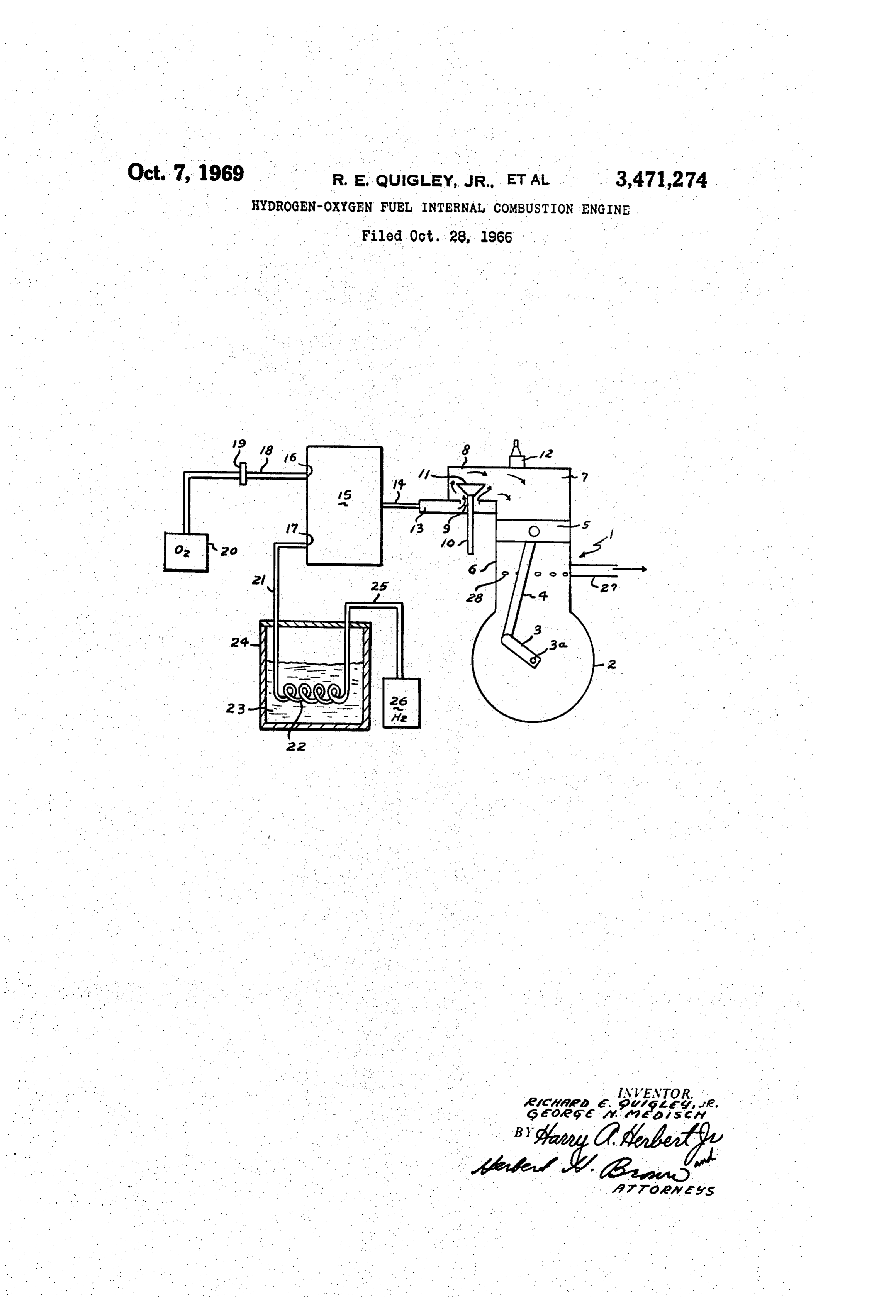
combustion chamber. - In the figure, reference character 1 generally designates 20 by diagram the outline of an automotive engine of well known design. Only those parts of the engine are shown
The invention described herein may be manufactured in detail which are concerned with the invention. It will and used by or for the United States Government for be understood that the engine has the usual crank shaft, governmental purposes without the payment to us of any flywheel, timing gears and valve lifting levers, also a suit royalty thereon. 25 ably positioned water jacket, water pump and oil pressure Prior to this invention, oxygen and hydrogen have been !connections. The crankcase is indicated at 2 and a rotata introduced as a mixture into the combustion chamber ble crank is shown at 3 which is secured to a crankshaft through separate cam-operated valves. The result was 3a. A rod 4 is connected between the crank to a pintle that when these engines are operated according to the in a piston 5. The latter may have piston rings (not Otto cycle, they produce severe detonations. The com- 30 shown). The crankcase carries an upright cylinder 6 at busted gas movements would tend to scrub the cylinder the top position, the upper portion of which serves as a walls of the lubricant and cause over-heating of the com combustion chamber 7. The latter is provided with a hori bustion chamber walls. Backfiring of the charge through Zontal rectangularly shaped extension 8 having an inlet the manifold, caused by localized excessive heat zones in opening 9 along the bottom surface. A stem 10, carrying the cylinder walls may also be present, which gives rise 35 an inlet valve 11 at the top, reciprocates in this opening. to overheating of the valves. These heated spots often The valve has a tapered periphery which can fit snugly would cause premature igniting of the gases. From the within a valve seat of similar shape and formed about operation standpoint, an engine of this character runs the opening 9. The stem 10 is adapted to be moved ver rough and uneven, is hard to start, and exhibits consider tically by a suitably positioned cam-operated rod (not able loss of power. - 40 shown) which is precisely timed by the usual gears. A These difficulties do not appear to lie in any variation spark plug 12 is threaded into the top of the combustion from an optimum ratio between the hydrogen and the chamber. These is an opening in the lower wall of the oxygen content or the compression ratio, but instead, manifold 13 which serves as a vertical support for the appear to be due to a high flame speed within the com valve stem. The outer end of the manifold is closed ex bustion chamber. 45 cept for an opening which receives a conduit 14. Various proposals have been made to eliminate these A mixing tank, which could take the form of a car dangerous backfirings, for example, it has been proposed buretor in a standard engine is indicated at 15. This tank to introduce flame arresters in the induction passage of is provided with a pair of inlet openings 16, 17, the upper the manifold. However, the pressure wave created by the one of which leads by conduit 18 through an adjustable blowback would hurl these arresters out of position. In- 50 orifice device 19 of any suitable and well-known type to creasing the hydrogen flow (thus enriching the mixture a source of oxygen 20. The latter is in the gaseous form ratio) or the coolant water flow (which lowers head tem and under high pressure. The lower opening 17 is con peratures) appears to increase the missing effect of the nected through a conduit 21 to a coil 22 immersed in a engine drastically. bath 23 of liquid nitrogen contained in a closed tank 24. In accordance with our invention, we have discovered 55 Well known provisions are provided to maintain an ade that this rate of flame speed can be reduced in a degree quate filling of the liquid in the tank and also to vent the sufficient to provide satisfactory performance of the en nitrogen gas. The other end of the coil is connected gine without the use of the aforesaid arresters or with through a conduit 25 to a source of high pressure hydro out requiring any critical ratio of the hydrogen to the gen 26 in gaseous form.
OXygen. 60 It is apparent that the oxygen and the hydrogen are An object of the invention is to provide an improved caused to flow through their respective conduits into the method and structure by which the flame speed can be tank 15 where these elements are combined as a homo controlled in an internal combustion engine utilizing geneous mixture. This mixture is caused to flow through hydrogen-oxygen fuel. the conduit 14 and manifold 13 when the valve 11 is A more specific object is to provide an improved en- 65 lifted during the intake stroke of the piston. A four-stroke gine of the type mentioned and in which the combus cycle engine can be advantageously employed, and as tion takes place evenly through the power generating suming that the ignition at spark plug 12 has been properly portion of the cylinder, with no hot spots or backfiring timed through the usual type of gearing, combustion of of the explosions. the mixture will occur at practically constant volume However, a more general object is to improve the oper- 70 (Otto cycle). Since the power stroke exists for only a part ating characteristics of a hydrogen-oxygen engine by elim of the total time of the cycle, a flywheel (not shown) is inating the various causes for departure from the ideal used to smooth out the power pulses and so obtain, essen
Page 3
tially, a uniform rotation of the crankshaft. A vacuum out departing from the general principle and scope of exhaust pump (not shown) is preferably connected to the invention.
the exhaust pipe 27 to remove the products of combus We claim:
tion when the exhaust ports 28 are uncovered by the 1. In the art of eliminating local hot spots in the ex piston. plosion walls of an internal combustion engine which OPERATION OF THE IMPROVED GAS INTAKE operates on a mixture of oxygen and hydrogen, the step of mixing the oxygen and hydrogen before introducing
In accordance with our invention we supply the com the fuel into the combustion chamber, and the further bustion chamber with a cold homogeneous mixture of step of cooling one of the gases to a relatively low tem hydrogen and oxygen in order to avoid the preignition 10 perature prior to the mixing operation in order to intro problems and to reduce the flame speed such that there duce the gaseous mixture in a cold state into the com are no detonations present. The mixing operation is per bustion chamber. .
formed apart from the engine and specifically within the 2. The method according to claim 1 and in which the tank or pot 15 and at a pressure of preferably 153 p.S.i. hydrogen content is cooled to the cryogenic regime of gage. The tank can, of course, be structurally attached to 15 below -190 F.
the engine for manufacturing reasons. Essentially, it oper 3. In an internal combustion engine operating on the ates from the mixing standpoint entirely separate from combined explosive effect of oxygen and hydrogen, means the engine in order to assure a high degree of homogeneity for eliminating local hot spots in the walls of the con before the fuel is introduced into the combustion chamber. bustion chamber during the explosion, said means in The oxygen at source 20 is in the gaseous form and 20 cluding a tank external of the combustion chamber of at ambient temperature. The volume or rate of flow of the engine and within which the two gases are mixed for the oxygen into the mixing chamber can be regulated at introduction into said chamber, means for cooling one of the orifice 19. The hydrogen source 26 is passed through said gases to a temperature considerably below ambient a liquid nitrogen bath at the tank 24. The nitrogen is temperature prior to forming the mixture whereby the maintained at about -320 F. and the hydrogen emerges 25 mixture is introduced into the combustion chamber in a from the tank at a temperature of about -300' F. relatively cold state in order to reduce the rate of flame After passing through the cooling device, the gas flows speed within the chamber.
into the mixing pot 15 in order to be thoroughly mixed 4. Apparatus according to claim 3 and in which said with the introduced oxygen. The gaseous mixture has a cooling means operates only on the hydrogen component temperature in the preferred regime of -258 F. or even 30 of the mixture.
colder depending on the ratio of oxygen to hydrogen as 5. Apparatus according to claim 4 and in which said controlled by the orifice 19. It was shown during tests cooling means operates to lower the temperature of the that the lower the input temperature of the gas mixture hydrogen prior to mixing to a temperature such that the the greater decrease was obtained in the severity of det temperature of the mixture will be less than -190 F. onations of the engine during operation. 35
The cold gas mixture, upon reaching the combustion References Cited chamber is at a cryogenic regime of less than -190 F. UNITED STATES PATENTS at which temperature it tends to cool the walls of the chamber so as to eliminate any local hot spots which 1,275,481 8/1918 Seymour.
could bring on preignition. The cold condition of the 40 3,232,050 2/1966 Robinson et al. -------- 60-36 gas definitely reduces the severity of detonation during combustion so that there is little or no backfire to ruin U.S. C. X.R. the valves by overheating. The overall result is that the MORRIS O. WOLK, Primary Examiner engine operates quieter and has a longer operating life than the prior oxygen-hydrogen engine in which a mix 45 R. E. SERWIN, Assistant Examiner ture of gases is introduced into the combustion chamber U.S. C. X.R. at ambient temperature. 60-36; 123-1, 119
While a certain specific embodiment has been described, it is obvious that numerous changes may be made with
Provenance
- Collection
- Cited prior art
- Original PDF
- patentimages.storage.googleapis.com →
- Filed
- 1966-10-28
- Pages
- 3
- Method
- pdftotext (the PDF's own text layer) + pdftoppm 300dpi page scans
- Source
- Google Patents bibliographic record
- Granted
- 1969-10-07
- Inventors
- Richard E Quigley Jr; George N Medisch; United States Department of the Air Force
- Transcribed from
- patentimages.storage.googleapis.com →