patent · US4622924
Hydrogen engine
18 November 1986
Page 1 — bibliographic record
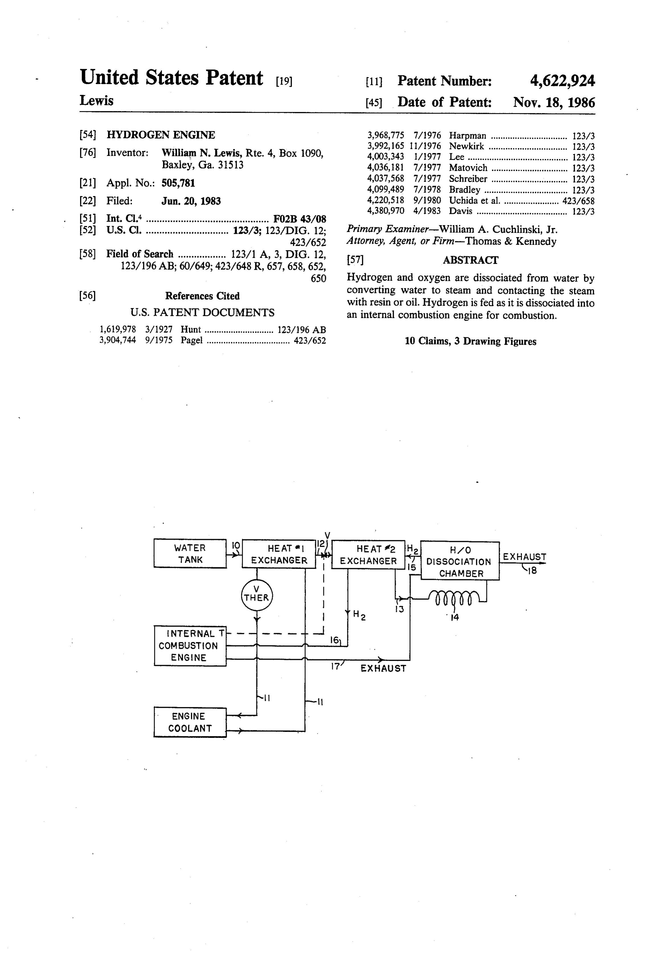
United States Patent (19) 11 Patent Number: 4,622,924 Lewis (45) Date of Patent: Nov. 18, 1986 54 HYDROGEN ENGINE 3,968,775 7/1976 Harpman ................................ 123/3 3,992,165 11/1976 Newkirk ................................. 123/3 76 Inventor: William N. Lewis, Rte. 4, Box 1090, 4,003,343 1/1977 Lee .......................................... 123/3 Baxley, Ga. 31513 4,036, 181 7/1977 Matovich ................................ 123/3 (21) Appl. No.: 505,781 4,037,568 7/1977 Schreiber ................................ 123/3 4,099,489 7/1978 Bradley ................................... 123/3 22) Filed: Jun. 20, 1983 4,220,518 9/1980 Uchida et al. ... 42.3/658 4,380,970 4/1983 Davis ...................................... 123/3 51) Int. Cl." .............................................. FO2B 43/08 52) U.S. Cl. ............................... 123/3; 123/DIG. 12; Primary Examiner-William A. Cuchlinski, Jr. 423/652 Attorney, Agent, or Firm-Thomas & Kennedy 58) Field of Search .................. 123/1 A, 3, DIG. 12, 57 ABSTRACT
650 Hydrogen and oxygen are dissociated from water by (56) References Cited converting water to steam and contacting the steam with resin or oil. Hydrogen is fed as it is dissociated into
3,904,744 9/1975 Pagel ................................... 423/652 10 Claims, 3 Drawing Figures
HEAT 2 HEAT 12 H2 H/O EXHAUST
EXCHANGER EXCHANGER DSSOCATION
CHAMBER
COMBUSTION
ENGINE
- ENGINE
COOLANT
Page 2
Drawing sheet — no readable text.
Page 3
Drawing sheet — no readable text.
Page 4
drogen is dissociated from oxygen, and igniting the
In another form of the invention a power generation
TECHNICAL FIELD process is provided wherein hydrogen is generated and This invention relates to methods and apparatuses for used as engine fuel at substantially the same rates of generating hydrogen and for utilizing hydrogen as a generation and fuel utilization so that hydrogen storage fuel for internal combustion engines. may be substantially avoided. The process comprises the steps of introducing water into a hydrogen-oxygen
BACKGROUND OF THE INVENTION dissociation apparatus through valve means controlled Upon combustion hydrogen releases a substantial by an engine throttle, dissociating hydrogen and oxygen
amount of energy which may be utilized in the genera as it isdissociation in the apparatus, and feeding the hydrogen being generated into the engine.
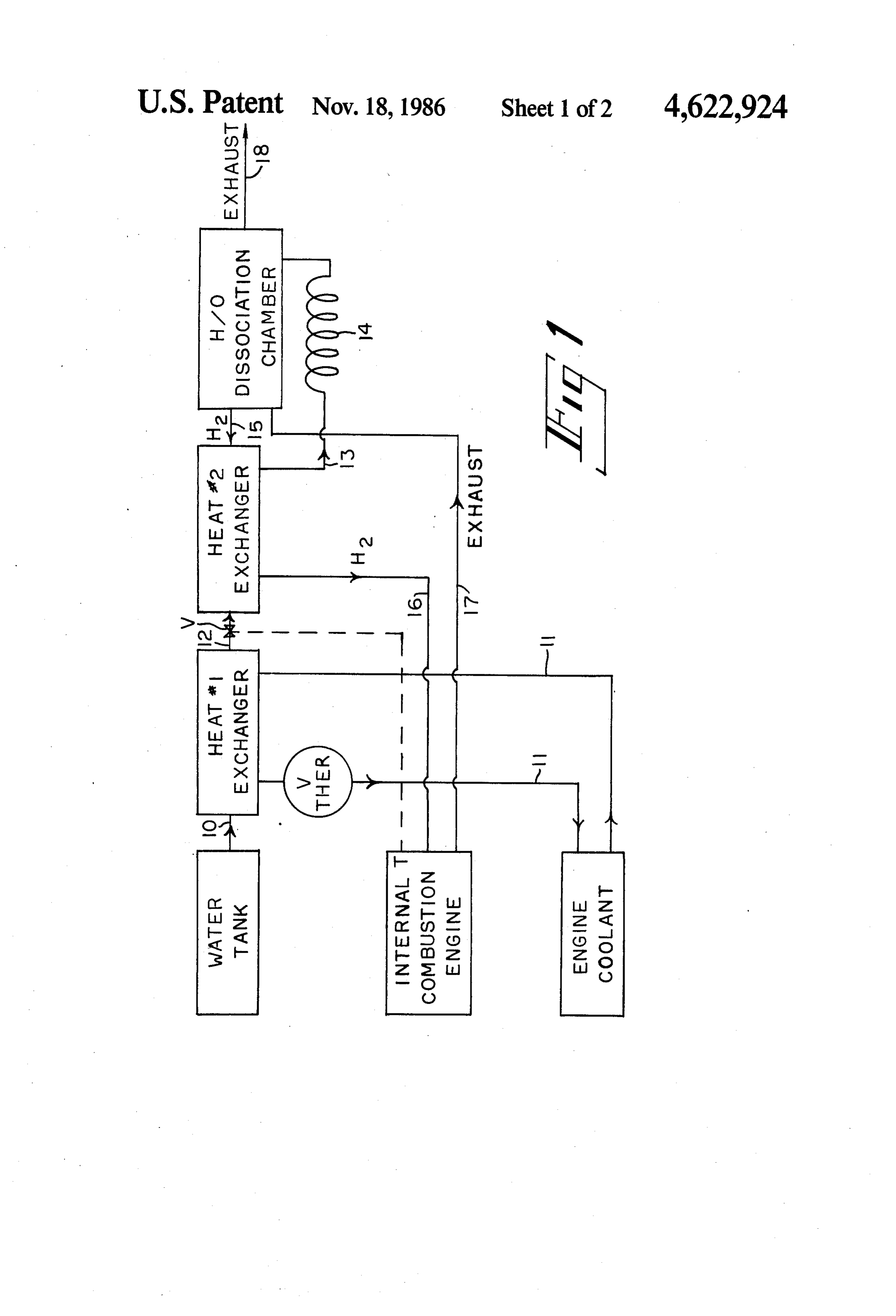
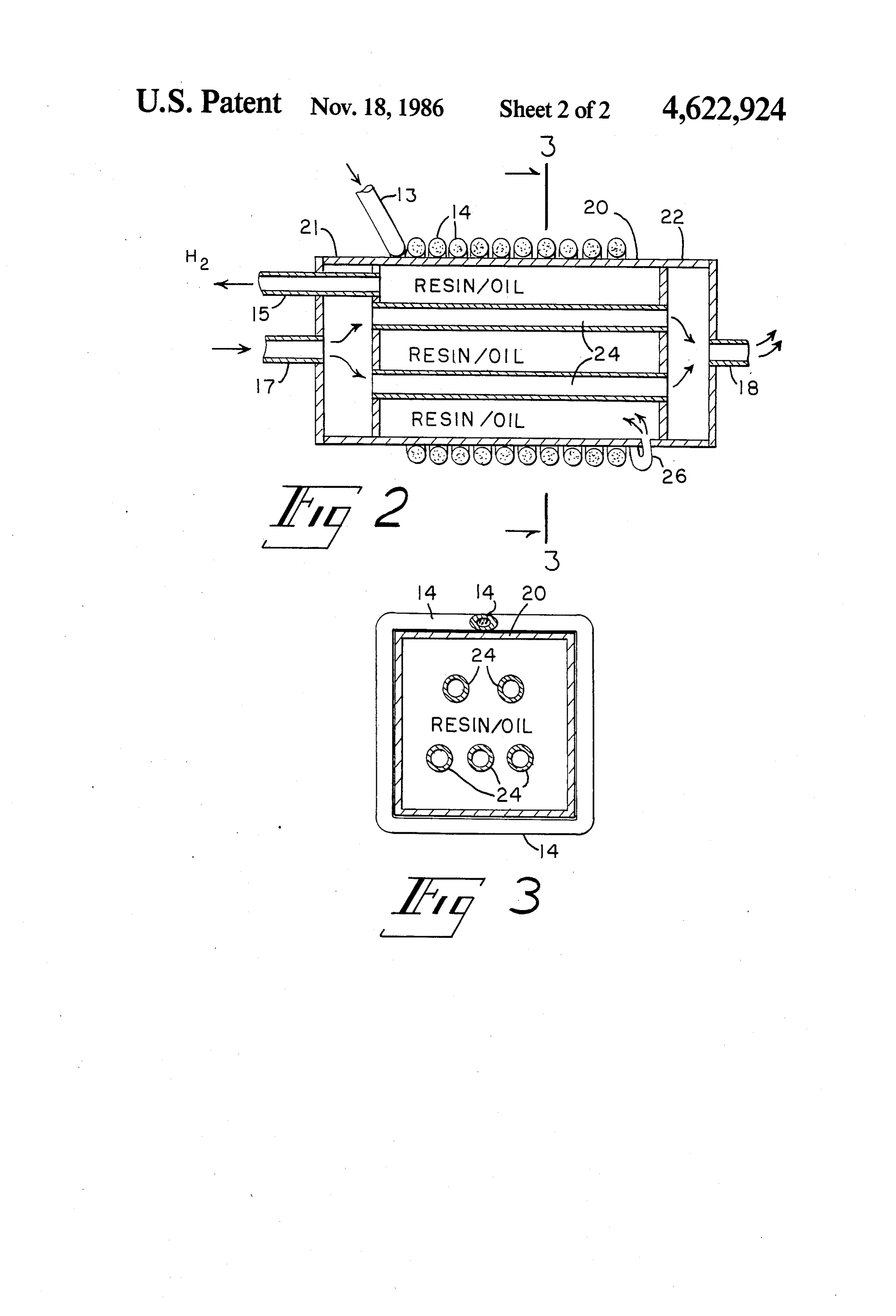
tion of power. However, since it is a chemically active In yet another form of the invention, a power genera element and therefore not available in the free state in tion system comprises an internal combustion engine, a nature in elemental gaseous form, it must be produced 15 fuel tank adapted to hold a supply of water, and a hy and stored for utilization in engines. drogen-oxygen dissociation chamber containing a sup In general, hydrogen is obtained from compounds by ply of oil or resin. The system further includes first breaking chemical bonds. This, of course, requires a conduit means for feeding water from the fuel tank to substantial amount of energy to accomplish. Though the hydrogen-oxygen dissociation chamber, heating there are many ways of liberating hydrogen from hy 20 means for converting water being fed through the con drocarbons, acids, bases and water, it is usually obtained duit means from a liquid to a gaseous phase, and second in commercial quantities from water or petroleum. conduit means for feeding hydrogen generated in the From hydrocarbons a mixture of methane and steam is hydrogen-oxygen dissociation chamber to the internal typically heated to a high temperature in the presence combustion engine for combustion therein. of catalysts in producing large quantities of hydrogen. 25 In still another form of the invention apparatus for From water hydrogen is produced by electrolysis. dissociating hydrogen and oxygen comprises a chamber Methods of producing hydrogen are more specifi housing oil or resin and conduit means passing through cally exemplified in U.S. Pat. Nos. 3,699,718, 3,786,138, the chamber through which hot gases may be passed to 3,816,609, 3,859,373, 4,069,304 and 4,202,744. These heat the oil or resin. A pipe is thermally coupled and methods generally include steam-light hydrocarbon 30 placed in communication with the chamber which pipe reforming, partial oxidation of hydrocarbons and other contains a mass of particulates into which water may be carbonaceous matter, and coal gasification (the Kellogg fed and phase changed into steam upon contact with process). particulates that have been heated by thermal conduc To date, hydrogen engines have had only very lim 35 tion from the chamber and the steam passed into the ited and specialized use, such as in propelling rockets camber and into contact with the oil or resin. and missiles and other military applications. They have BRIEF DESCRIPTION OF THE DRAWING not found general use as pewer sources for driving vehicles over public roads for a number of reasons. principles FIG. 1 is a schematic diagram of a system embodying Probably foremost among such reasons is the danger ticing processes of the invention which may be used in prac associated with the use of hydrogen for its propensity to of the invention. FIG. 2 is a cross-sectional combust and release vast amounts of energy in violent sociating hydrogen from oxygen view of apparatus for dis reactions. To transport gaseous hydrogen in a storage principles of the invention. in accordance with tank in vehicles would thus create a very substantial FIG. 3 is a cross-sectional view taken along plane danger to the motoring public. Another reason is that the expense and storage space requirements involved 45 3-3 of the apparatus illustrated in FIG. 2. are too high where hydrogen is to be produced from DETAILED DESCRIPTION hydrocarbons such as methane. Liquid water would With reference to the schematic diagram presented in not, of course, present a storage or expense problem. FIG. 1, a hydrogen engine that includes a hydrogen However, the rate by which hydrogen could be pro 50 generation duced from water by electrolysis would be insufficient tion enginesystem such as is seen to include an internal combus that conventionally used in power for use as an automative engine fuel.
Accordingly, it is to the provision of methods and which is water cooled with which ing an automotive vehicle
has a throttle T and conventional engine cool apparatuses for producing hydrogen and utilizing it as it ant system. A fuel tank is provided which houses a is generated as a fuel in internal combustion engines to 55 supply of water. A conduit 10 extends from the water which the present invention is primarily directed. tank to a first heat exchanger that is coupled with the SUMMARY OF THE INVENTION engine coolant system via a system of conduits 11 in which a thermionic valve is employed. A conduit 12
In one form of the invention, a gas generation process extends from the first heat exchanger in fluid communi comprises the steps of forming a stream of steam at a 60 cation with conduit 10 to a second heat exchanger temperature of between 500F. and 900 F. and passing through a valve V that is coupled with and controlled the stream through a body of oil or resin whereupon the by the internal combustion engine throttle T. Another stream of steam is at least partially dissociated into hy conduit 13 extends from the second heat exchanger in drogen and oxygen. fluid communication with conduit 12 to a convoluted In another form of the invention a power generation 65 conduit 14 which is in fluid communication with a hy process comprises the steps of forming a stream of drogen-oxygen dissociation chamber. A conduit 15 steam at a temperature of between 500' F. and 900' F., extends from the dissociation chamber back to the sec contacting the stream with resin or oil whereupon hy ond heat exchanger in fluid communication with an
Page 5
other conduit 16 that extends from the second heat the engine. The heat from the exhaust passes through exchanger to the internal combustion engine. Within the conduit 17 and into the intake manifold 21 and the internal combustion engine itself the conduit 16 is through pipes 24 within the tank 20 and from there connected to the carburation or fuel injection subsys through the outlet manifold to the tail pipe 18. This heat tem. Finally, another conduit 17 extends from the en is transmitted to the body of resin or oil in maintaining gine exhaust system of the internal combustion engine its proper temperature.
to the dissociation chamber and into communication It is not fully understood how hydrogen and oxygen with an exhaust pipe 18. is dissociated with the just-described system since the With reference next to FIGS. 2 and 3 the hydrogen temperatures involved are substantially less than that oxygen dissociation chamber is seen to include a tank 20 10 previously thought necessary to produce the energy to one end of which an intake manifold 21 is secured levels required in breaking the oxygen-hydrogen bond. and to the opposite end of which an outlet manifold 22 Apparently the low pressure stream of steam, however, is secured. Five pipes 24 extend through the tank 20 when brought into contact with the surface of the resin between the two manifolds. The conduit 17 is seen to be or oil, is catalyzed in some manner so that the required connected with the intake manifold while the tail pipe 15 temperature to produce the necessary energy is low 18 is coupled with the outlet manifold. The conduit 13 ered. In any event, the system and process has been is seen to merge into the convoluted form of the conduit found to work well in propelling automobiles over 14 which is wrapped tightly around the tank 20 so as to roads solely with a supply of water being used as the be thermally coupled with it. Within the convoluted engine fuel in addition to the supply of resin and oil, and conduit 14 is packed a mass of particulates such as com 20 the use of an auxiliary preheating system. mon iron-bearing rocks. The end of the convoluted OPERATIVE EXAMPLE conduit is provided with an elbow joint 26 through which fluids may be inputted into the bottom of the tank The just described power generation apparatus has 20. been successfully used by mounting it upon an approxi The conduit 15 is seen to extend from the tank 20 25 mately 4,000 pound Ambassador model automobile sold through the intake manifold to the second heat ex by American Motors Corporation with the hydrogen changer. The tank 20 houses a supply of resin or oil. engine's dissociation chamberoriented vertically and Various kinds of oils may be employed such as mineral less than half filled with 8 pounds of standard grade oils and petroleum oils. The preferred resin is a gum or pine tar resin although soybean oil may also be used. 30 (Marion) pine resin and with the steam generating pipe filled with iron rocks. The Ambassador's standard 232
The gum resin may be obtained from Southern, yellow cubic inch internal combustion engine was fueled solely or long-leaf pine trees.
Prior to operation the resin or oil within the hydro with gases generated by the hydrogen engine. The resin and tap water were both heated to approximately 600 gen-oxygen dissociation chamber is preheated to a tem F. and water fed to the dissociation chamber at a rate of perature of between 500' F. and 900' F. as by the use of 35 1 gal/hour. Steam was developed at 5 pounds/square an unshown auxiliary preheat means of conventional inch and passed through the resin continuously for a construction. The temperature of the resin should be at period of approximately 2 hours while the automobile least 500" F. since below that temperature efficiency was being goes down in that an insufficient quantity of hydrogen is of 60 milesdriven per upon public roads at an average speed hour. The temperature of the steam was generated. Conversely, above approximately 900 F., found to drop from approximately
600' F. to approxi depending upon the particular resin or oil employed, mately 500 as it passed through the second heat ex that resin or oil may tend to break down into another changer. Water was consumed at a rate of approxi State.
Once the resin or oil has achieved the proper temper mately 1 gal/hour and resin consumed at a rate of ap ature the engine is operated in the following manner. proximately pound/hour.
It should be understood that the just-described em
Water is fed as by unshown pump means from the water bodiment merely illustrated principle of the invention in tank to the dissociation chamber through the conduits one particular form. Many modifications, additions or 10, 12 and 15, the two heat exchangers and the valve V.
In passing through the first heat exchanger the water is deletions may, of course, be made thereto without de preheated from the heat of the engine coolant. The 50 parture from the spirit and scope of the invention as set water is then fed through the valve V to the second heat forth I in the following claims.
claim:
exchanger with the valve V being controlled by the 1. A gas generation process comprising the steps of position of the engine throttle T. From the second heat forming a stream of steam at a temperature of between exchanger the water is fed through conduit 13 and into 500 F. and 900' F. and passing the stream through a the convoluted pipe 14 where it comes into contact 55 body of oil or resin whereupon the stream of steam is at with the heated mass of particulates and is converted to least partially dissociated into hydrogen and oxygen. a low pressure stream of steam. From here the low 2. The gas generation process of claim 1 wherein the pressure stream of steam passes slowly through the body of resin or oil within the hydrogen dissociation stream of steam is passed through a body of gum resin. chamber. Upon contact with the resin or oil the steam is 60 stream3. The gas generation process of claim 1 wherein the dissociated into hydrogen and oxygen. of steam is passed through a body of pine resin. From the dissociation chamber the dissociated hydro 4. A power generation process comprising the steps gen and oxygen passes through a conduit 15 to the of forming a stream of steam at a temperature of be second heat exchanger wherein the hydrogen is cooled tween 500 F. and 900' F.; contacting the stream with down somewhat from its 600 F. temperature. The 65 resin or oil whereupon hydrogen is dissociated from hydrogen is then fed directly through conduit 16 into oxygen; and igniting the hydrogen.
the fuel intake system of the engine where it is ignited to 5. The power generation process of claim 4 where the produce energy in driving the internal components of stream of steam is passed through a body of resin.
Page 6
6. The power generation process of claim 4 wherein 9. Apparatus for dissociating hydrogen and oxygen the stream of steam is passed through a body of oil. comprising a chamber housing oil or resin; conduit 7. The power generation process of claim 4 wherein means passing through said chamber through which hot the hydrogen is ignited in an internal combustion en gases may be passed to heat said oil or resin; a first pipe gine. in communicatioon with a water tank and thermally 8. A power generation process wherein hydrogen is coupled and communicating with said chamber, said generated and used as engine fuel at substantially the first pipe containing a mass of particulates into which same rates of generation and fuel utilization so that water may be fed and phase-changed into steam upon storage may be substantially avoided, and with said O contact with particulates that have been heated by ther process comprising the steps of introducing water into a mal conduction from said chamber and the steam passed hydrogen-oxygen dissociation apparatus through valve into the chamber and into contact with the oil or resin; and a second pipe communicating with said chamber means controlled by an engine throttle, dissociating through which hydrogen and oxygen dissociated from hydrogen and oxygen in the dissociation apparatus by steam contacted with said oil or resin within said cham vaporizing the water to stream at a temperature of be 15 ber may be conveyed out of said chamber. tween 500 F. and 900 F. and contacting the steam with 10. The apparatus of claim 9 cherein said pipe is con oil or resin, and feeding the hydrogen as it is generated voluted about said dissociation chamber. into the engine for combustion therein. k sk e k
Provenance
- Collection
- Cited prior art
- Original PDF
- patentimages.storage.googleapis.com →
- Filed
- 1983-06-20
- Pages
- 6
- Method
- pdftotext (the PDF's own text layer) + pdftoppm 300dpi page scans
- Source
- Google Patents bibliographic record
- Granted
- 1986-11-18
- Inventors
- William N. Lewis
- Transcribed from
- patentimages.storage.googleapis.com →