patent · US5224457
Dual fuel electronic control system
6 July 1993
Page 1 — bibliographic record
United States Patent (19) 11 Patent Number: 5,224,457 Arsenault et al. (45) Date of Patent: Jul. 6, 1993 54) DUAL FUEL ELECTRONIC CONTROL 4,876,988 10/1989 Paul et al. SYSTEM 4,909,209 3/990 Takahashi ...................... 123/27 GE 4,936,280 6/1990 Langlois ... 123/578 (75) Inventors: Jeff Arsenault, Toronto; Wendelin 4,953,55 9/1990 Fehr et al............................ 123/526 Goetz, Kitchener; James Larocque, 4,955,326 9/1990 Helmich ... ... 123/577 Eden Mills, all of Canada 5,092,305 3/1992 King ........ ... 123/27 GE 5, 7,802 6/1992 Durbin . ... 123/27 GE (73 Assignee: Deere & Company, Moline, Ill. 5,136,986 8/1992 Jensen ............................ 123/27 GE (21) Appl. No.: 843,771 FOREIGN PATENT DOCUMENTS 22 Filed: Feb. 28, 1992 00487.30 4/1977 Japan ................................... 23/577 51 Int. Cl.............................................. FO2M 21/02 0029764. 2/1984 Japan ................................... 123/577 52 U.S. C. .............................. 123/526; 123/27 GE; OTHER PUBLICATIONS 123/577; 123/578 Xylinx, Inc., "The Programmable Gate Array Data
(56) References Cited Primary Examiner-E. Rollins Cross
Re. 26,145 1/1967 Friddell . 57) ABSTRACT 2,678,030 5/954 Bader et al. ......... ... 123A27 GE A dual fuel system for a diesel engine includes a liquid
(diesel) fuel injection system controlled by an engine
4,278,064 7/1981 Regueiro ............................. 123/526 electronic control unit (ECU) and a source of gaseous 4,463,734 8/1984 Akeroyd ............................. 23A526 fuel such as natural gas. A metering valve and a mixer 4,499,885 2/985 Weissenbach et al. ............. 123/526 controls introduction of gaseous fuel from the natural 4,505,249 3/1985 Young ................................. 123/577 gas fuel source into combustion air for the engine. An 4,517,928 5/1985 Wolters ............................... 23/526 electronic governor controls the metering valve and a 4,520,766 6/1985 Akeroyd ............................. 123/577 link controller coordinates operation of the ECU and 4,520,785 6/1985 Batchelor ...................... 123A27 GE 4,527,516 7/1985 Foster . the governor. Preferably, a regulator regulates the natu 4,535,728 8/1985 Batchelor . ral gas pressure supplied to the metering valve. A shut 4,603,674 8/1986 Tanaka ................................ 123/575 off valve controls communication of natural gas be 4,614,168 9/1986 Batchelor . tween the source and the regulator. The link controller 4,619,240 10/1986 Bedford et al................. 123/27 GE also controls the shut-off valve as a function of sensed 4,637,353 1/1987 Codrington . conditions.
4,865,001 9/1989 Jensen . 7 Claims, 57 Drawing Sheets
Page 2
Drawing sheet — no readable text.
Page 3
Drawing sheet — no readable text.
Page 4
Drawing sheet — no readable text.

Page 5
Drawing sheet — no readable text.
Page 6
Drawing sheet — no readable text.
Page 7
PLNKN
VCC
ECUS
PWGND
ECUGRND
BCGRND
NGWolve POSn
Diesel
Speed increment UserDiesel Speed Decrement User Duo Fue Low NGPressure increment Intoke AirTemp Decrement
into keAir
RPM
Page 8
Drawing sheet — no readable text.
Page 9
Drawing sheet — no readable text.
Page 10
Drawing sheet — no readable text.
Page 11
Drawing sheet — no readable text.
Page 12
Drawing sheet — no readable text.
Page 13
Drawing sheet — no readable text.
Page 14
Drawing sheet — no readable text.
Page 15
Drawing sheet — no readable text.
Page 16
Drawing sheet — no readable text.
Page 17
Drawing sheet — no readable text.
Page 18
Drawing sheet — no readable text.
Page 19
Drawing sheet — no readable text.
Page 20
Drawing sheet — no readable text.
Page 21
Drawing sheet — no readable text.
Page 22
DD D DO N N OOD O DOO O RESETB
area B a- 57
IO XTL1-BCK-IO49,
A A A. A C W 66 A 1. A 1 1 1 AA as a & CS1 B-ID50 55
a - a - are are - I52 53 I I I I I I I I I I I I I I I C re 53 Eggs:
NN NNNNNNNN
GG GIGIGIGIGIGIGIG
Page 23
Drawing sheet — no readable text.
Page 24
Drawing sheet — no readable text.
Page 25
Drawing sheet — no readable text.
Page 26
Drawing sheet — no readable text.
Page 27
Drawing sheet — no readable text.
Page 28
Drawing sheet — no readable text.
Page 29
Drawing sheet — no readable text.
Page 30
Drawing sheet — no readable text.
Page 31
Drawing sheet — no readable text.
Page 32
Drawing sheet — no readable text.
Page 33
Drawing sheet — no readable text.
Page 34
Drawing sheet — no readable text.
Page 35
Drawing sheet — no readable text.
Page 36
Drawing sheet — no readable text.
Page 37
Drawing sheet — no readable text.
Page 38
Drawing sheet — no readable text.
Page 39
Drawing sheet — no readable text.
Page 40
Drawing sheet — no readable text.
Page 41
Drawing sheet — no readable text.
Page 42
Drawing sheet — no readable text.
Page 43
Drawing sheet — no readable text.
Page 44
Drawing sheet — no readable text.
Page 45
Drawing sheet — no readable text.
Page 46
Drawing sheet — no readable text.
Page 47
Drawing sheet — no readable text.
Page 48
Drawing sheet — no readable text.
Page 49
Drawing sheet — no readable text.
Page 50
Drawing sheet — no readable text.
Page 51
Drawing sheet — no readable text.
Page 52
Drawing sheet — no readable text.
Page 53
Drawing sheet — no readable text.
Page 54
Drawing sheet — no readable text.
Page 55
Drawing sheet — no readable text.
Page 56
Drawing sheet — no readable text.
Page 57
Drawing sheet — no readable text.
Page 58
A/ESE7 (DELAY CAMGAOMAAP Al/4A. AA7
SAFED SE7AO/W7
WG SOLAWOO AZO7
TORQUE SELECT NORM4L
AU4/. A UEZ. OAAWGEOMEA? OESEL
SAEAD
WG SOYAWOD A/SAAZAA)
OAF
WOAMAZ
Page 59
Sor senses the natural gas pressure and the link control
DUAL FUEL ELECTRONIC CONTROL SYSTEM ler automatically closes the shut-off valve and causes
BACKGROUND OF INVENTION
the engine to be run on solely diesel fuel under the control of the ECU if the sensed natural gas pressure is
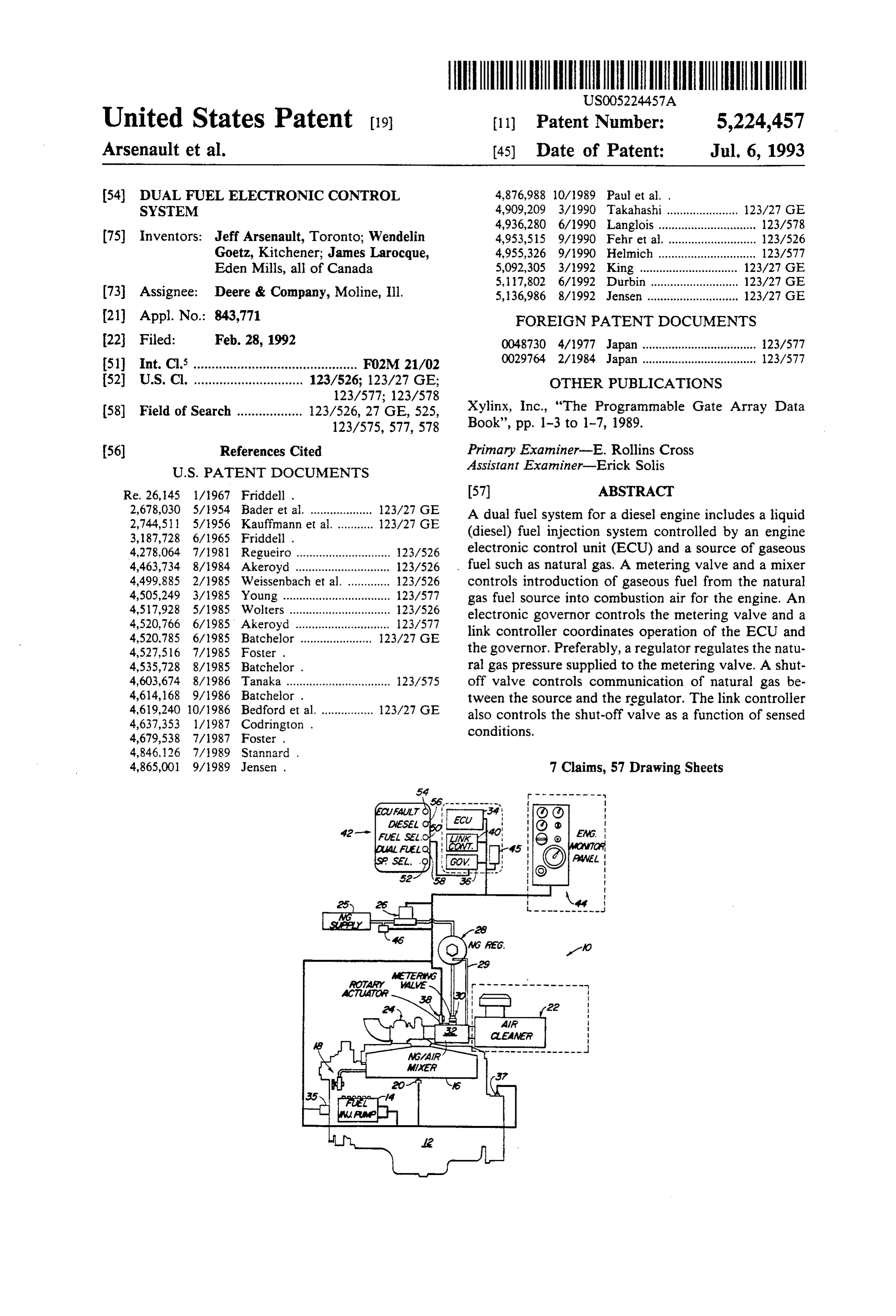
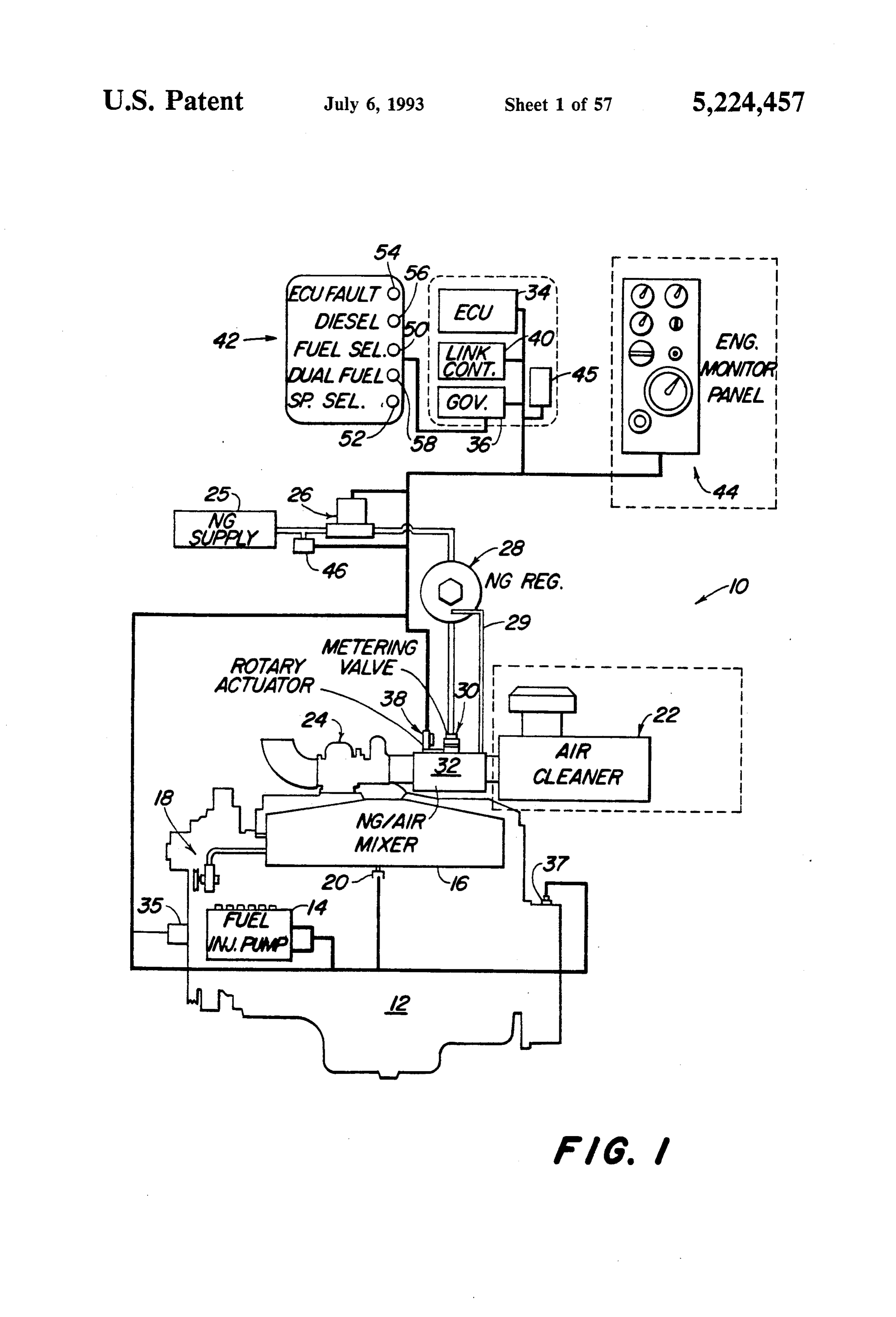
The present invention relates to a system for selec 5 below a certain limit. The link controller also switches tively supplying a diesel engine with diesel fuel only or the engine from solely diesel fuel to a combination of with a combination of diesel fuel and a gas fuel such as natural gas and the diesel fuel in response to an operator natural gas or propane, and for controlling operation of generated command signal. Thus, the invention pro the engine in both fuel supply situations. vides an all electronically controlled diesel pilot ignited Dual fueled engines, using natural gas in the intake 10 natural gas engine. The link controller links together a system and diesel pilot fuel to ignite the mixture, offer production mechanical/electronic diesel injection sys economic benefits with regard to lowering fuel costs. A tem with a production isochronous electronic natural stationary engine, used for irrigation or generator appli gas governing system. It includes safety shutdown fea cations, offers high natural gas utilization due to its high 15 tures, and controls operation on either diesel or dual load factor. fuel, depending on the input conditions. The invention Currently available natural gas engine fumigation allows maximum use of natural gas as a fuel for a diesel systems use mechanical means to meter the natural gas, engine, while ensuring that the engine is operated such as either venturi valves in combination with pres within accepted temperature and pressure limits. sure regulators or mechanically controlled throttle valves. These systems do not allow for precise metering BRIEF DESCRIPTION OF THE DRAWINGS over the engine operating range. In fact, such systems FIG. 1 is a schematic diagram of a dual fuel engine typically included mechanical governing or no govern system according to the present invention. ing at all, except venturi type mixers in the intake sys FIGS. 2a-2e are schematic diagrams illustrating the tem. Such systems are not very accurate. As a result, the switches and indicators which are part of the operator's engine may be over-fueled and harmed or destroyed, or 25 it may operate in an unsatisfactory manner. Addition control panel of FIG. 1.
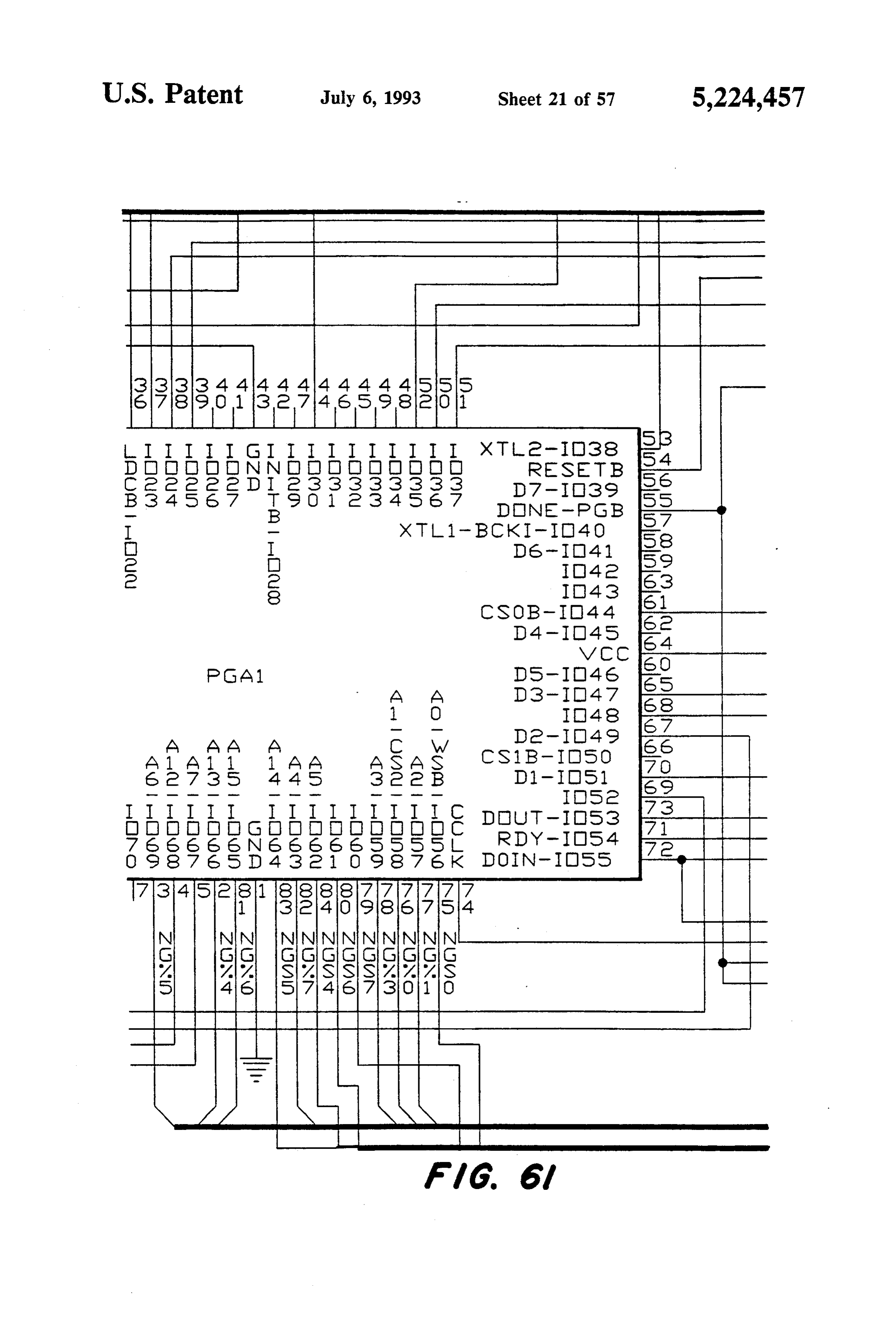
FIG. 3 is a schematic block diagram illustrating the ally, such systems do not adjust diesel engine operation to optimize the use of natural gas. Furthermore, the user connections tion with of the link controller of the present inven other components of a dual fuel engine sys of such a system must decide if the engine should be run on dual fuel or on diesel. Also, such systems do not 30 ten.
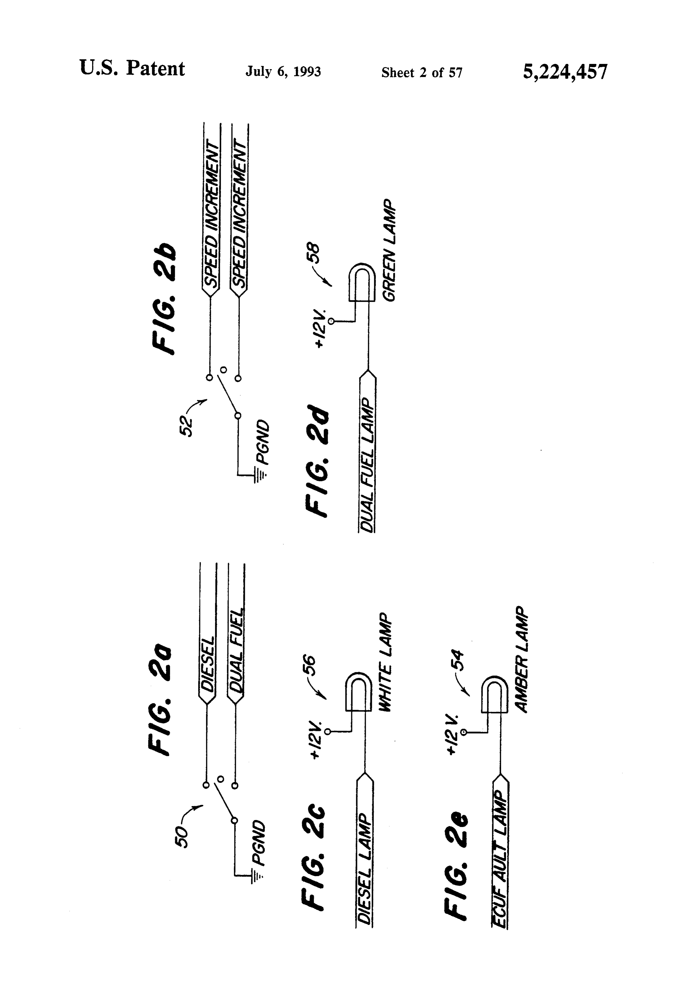
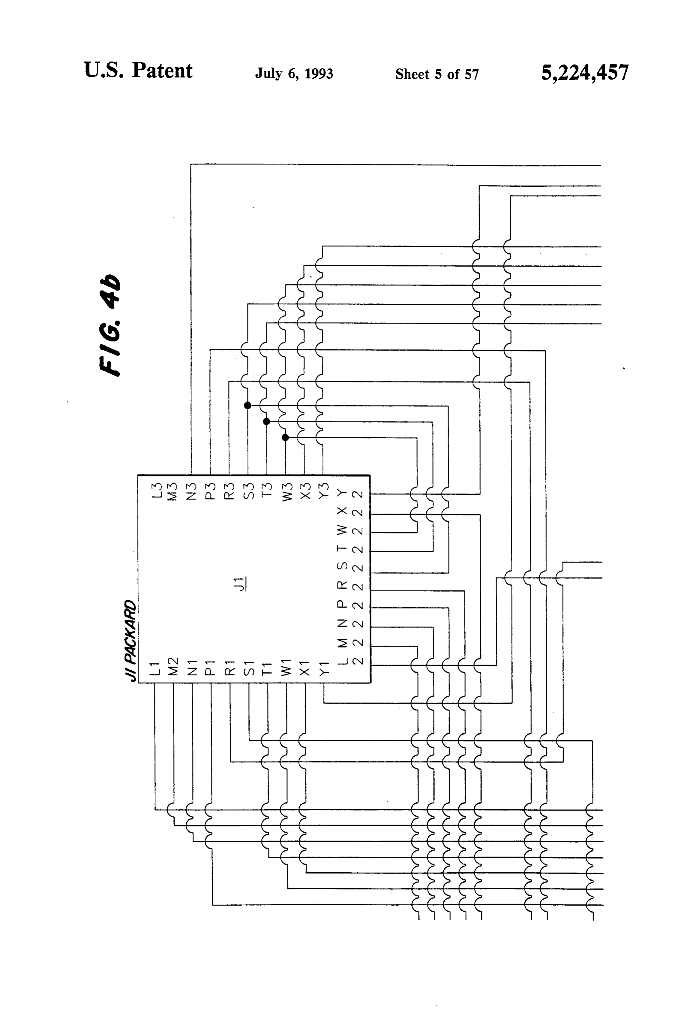
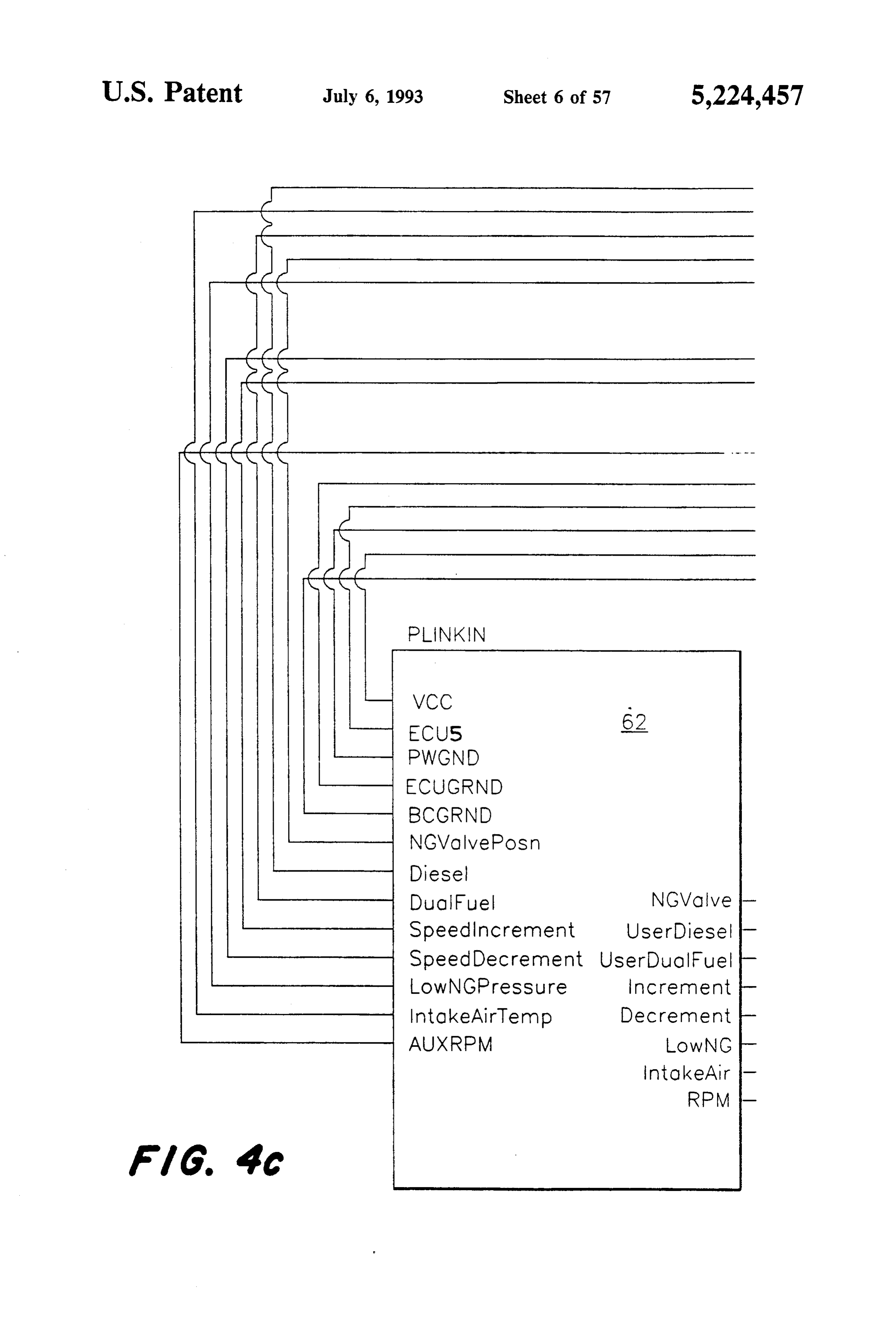
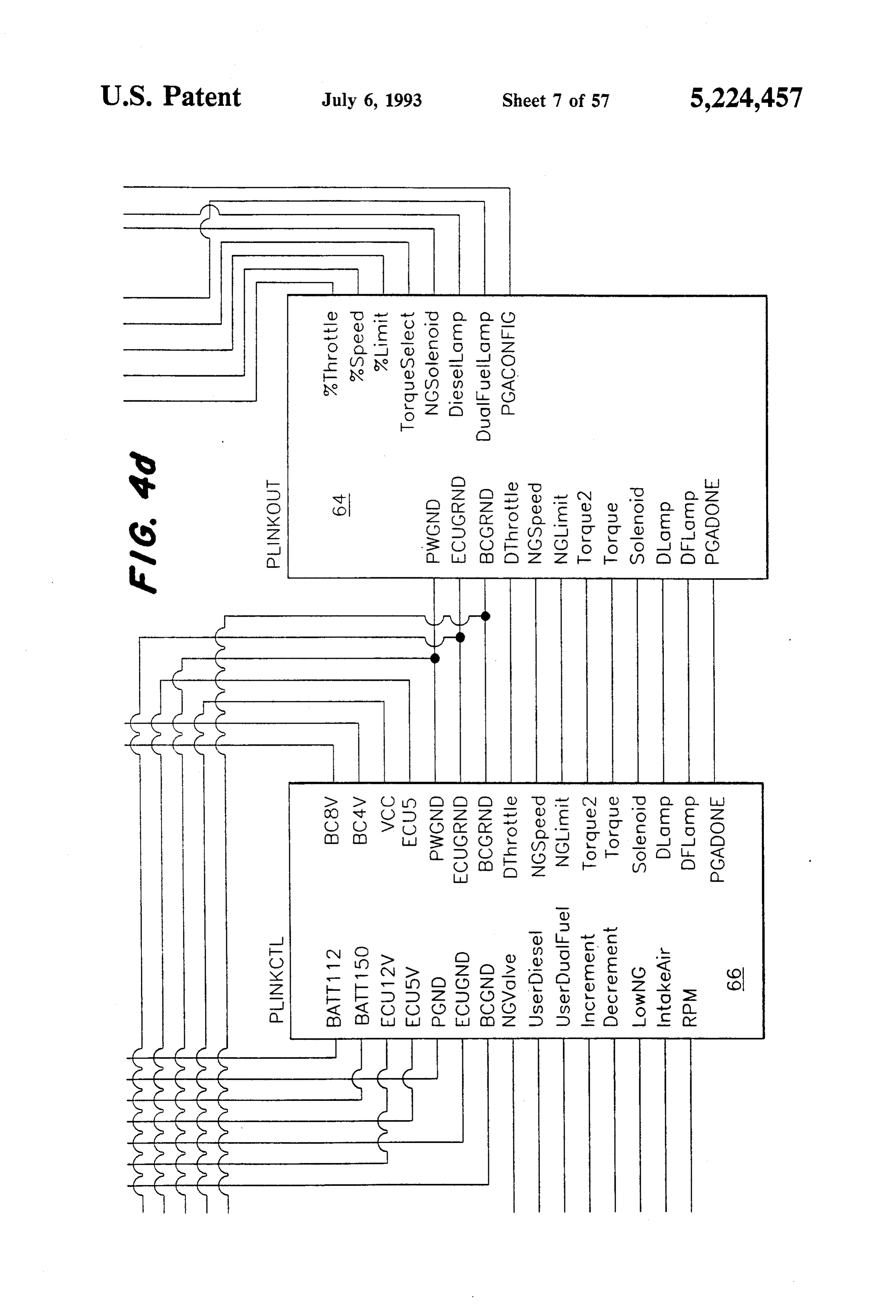
provide for safety shutdowns when using natural gas FIG. 4a shows the arrangement of FIGS. 4b-4d. fuel. FIGS. 4b-4d are combined to form a schematic block diagram showing the three main components of the link
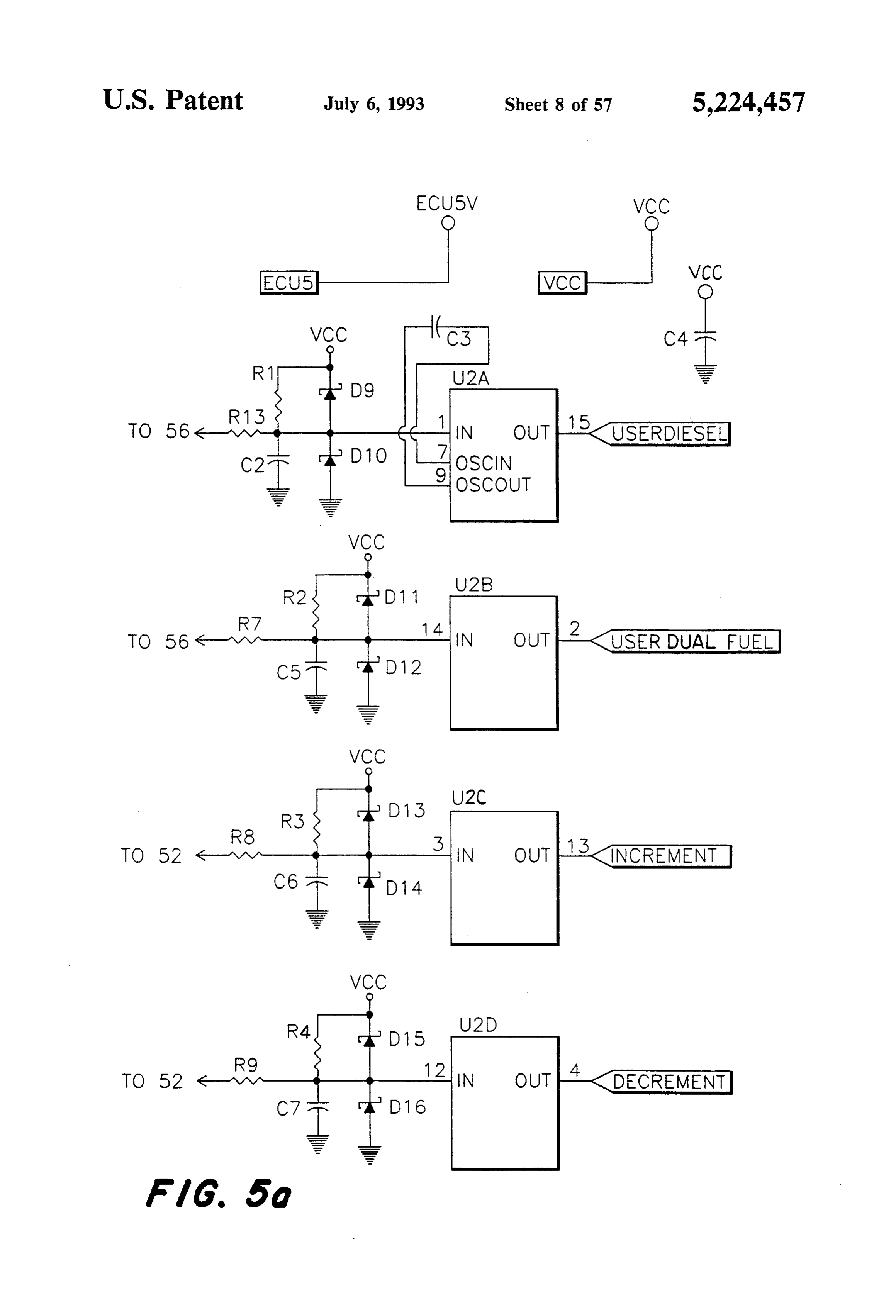
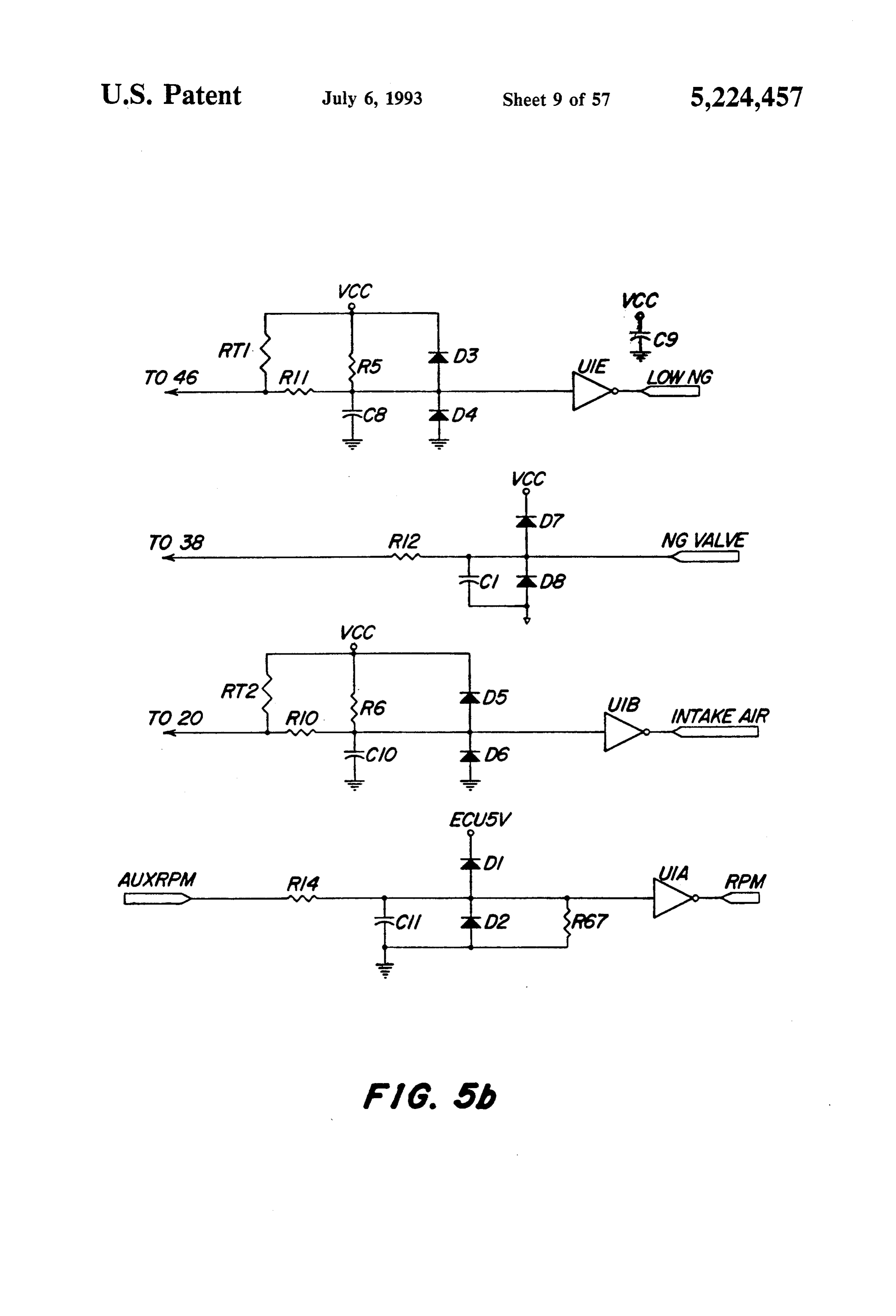
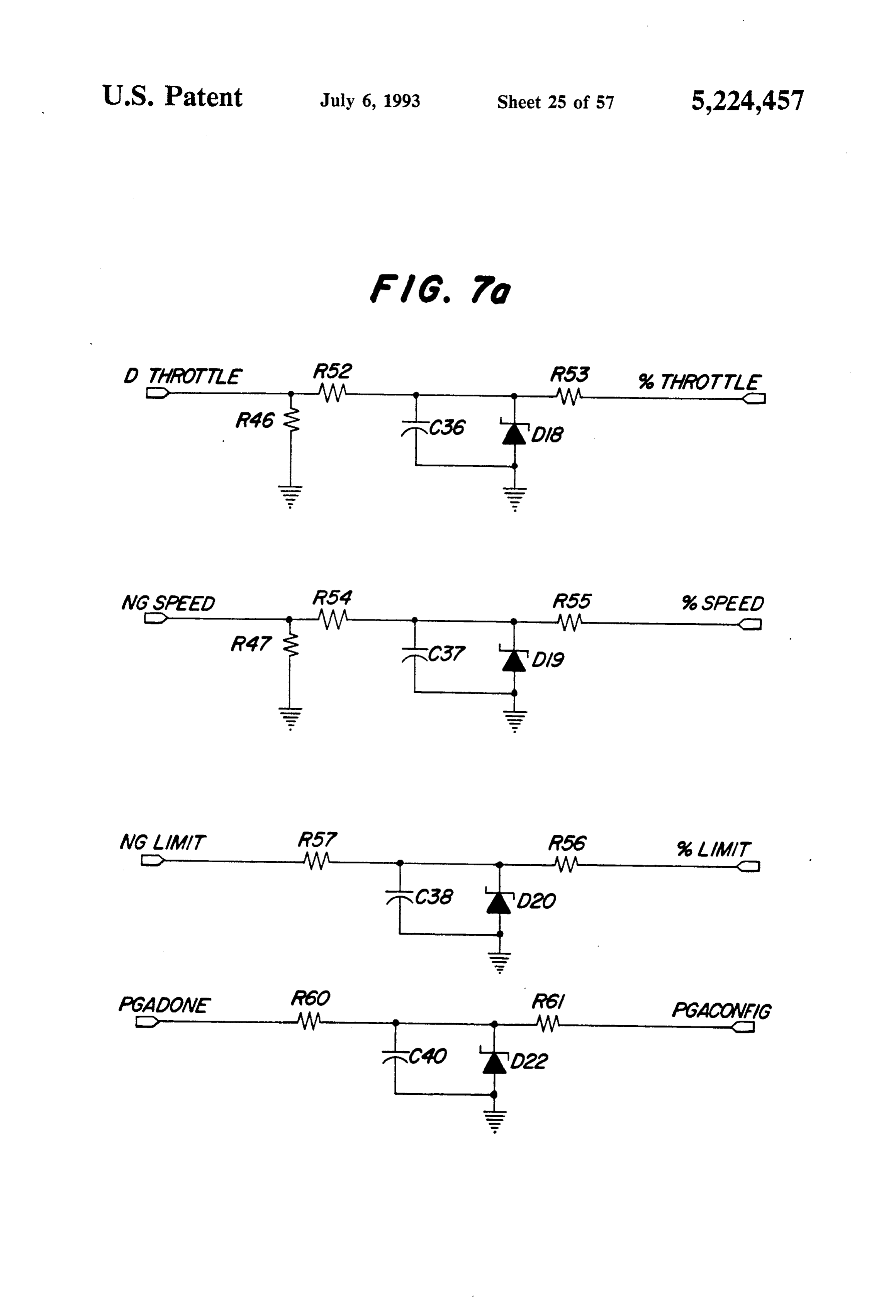
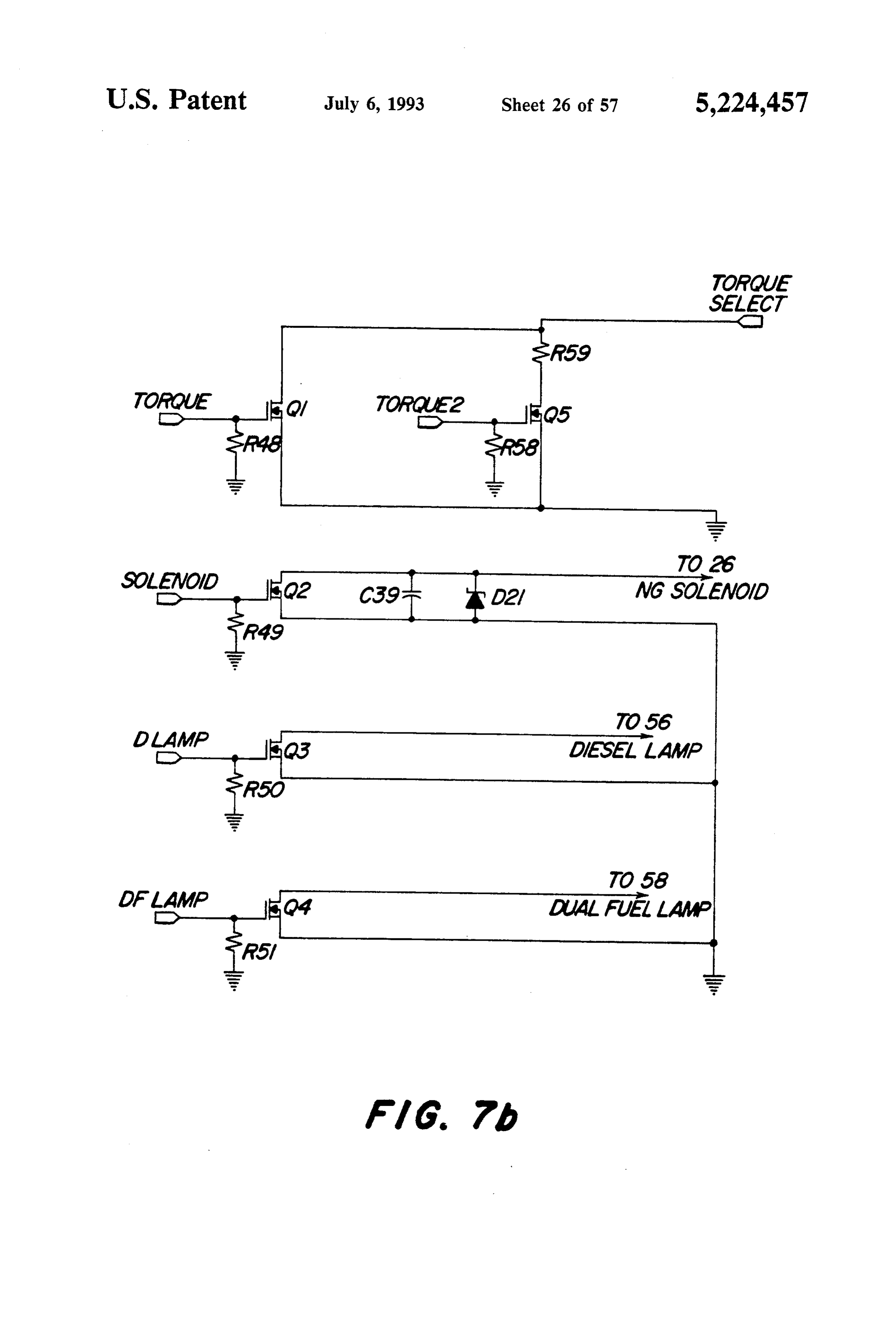
SUMMARY OF INVENTION controller and the connector which connects them to An object of the present invention is to provide an 35 the other parts of the dual fuel system. electronic control system for a diesel engine which may FIGS. 5a and 5b are circuit diagrams illustrating the be selectively supplied with diesel fuel or with a combi ent link controller input conditioning circuitry of the pres nation of diesel and natural gas fuels. VetOn.
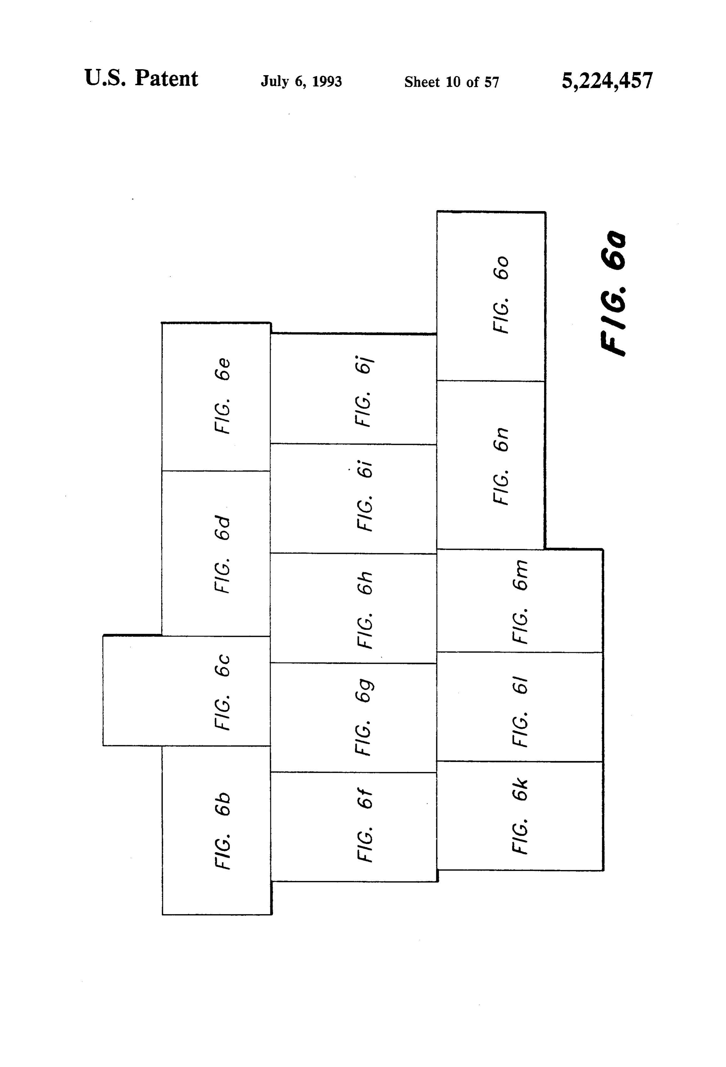
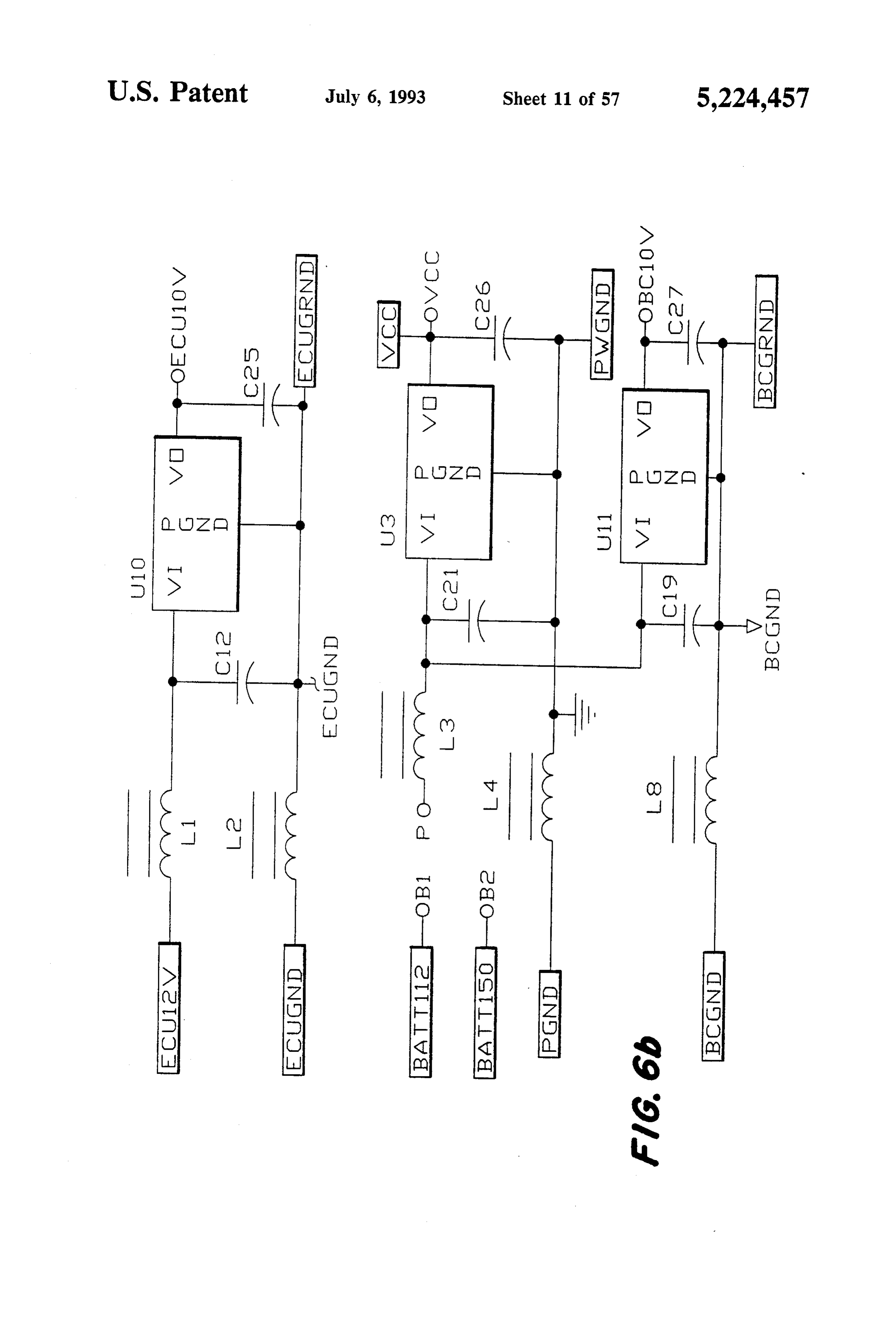
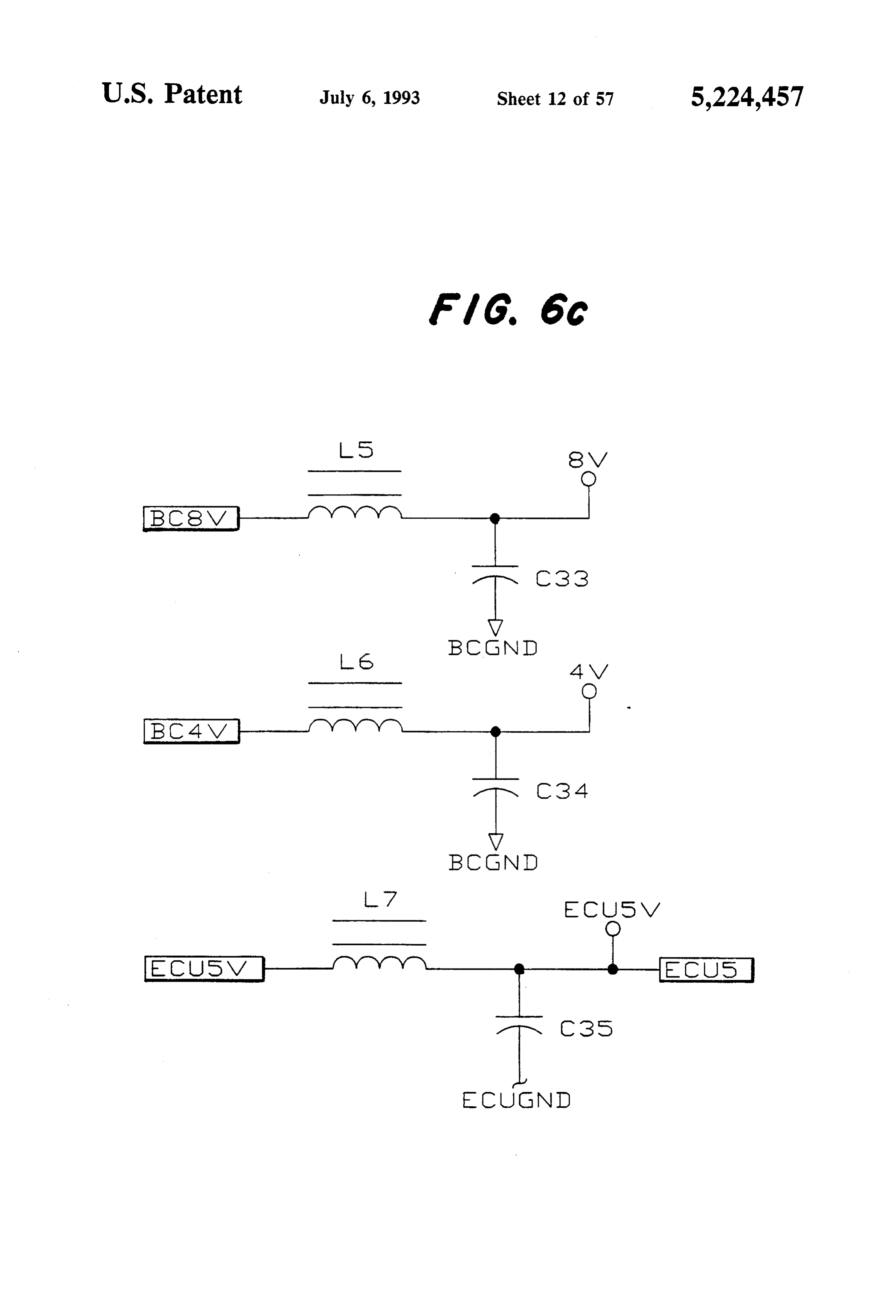
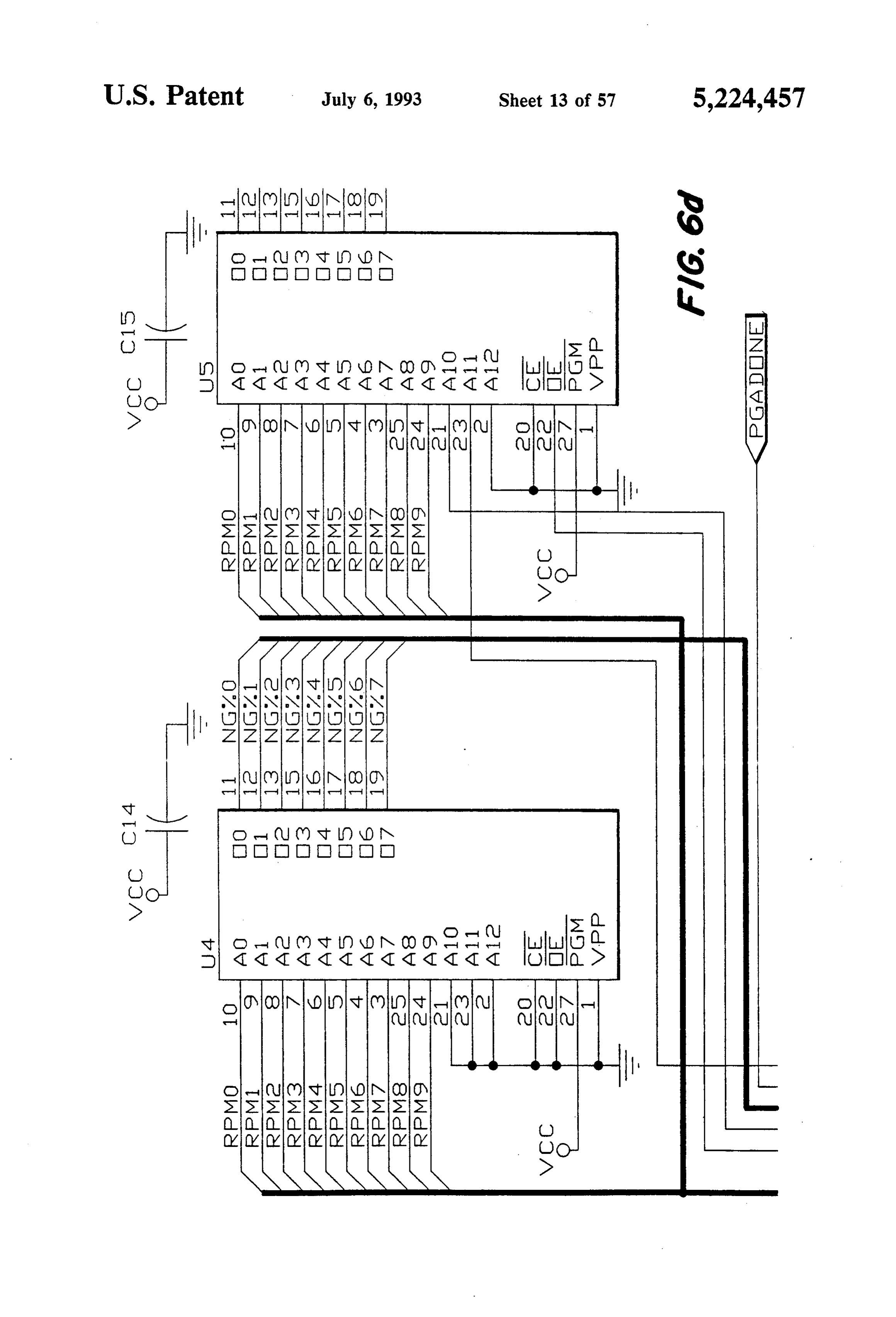
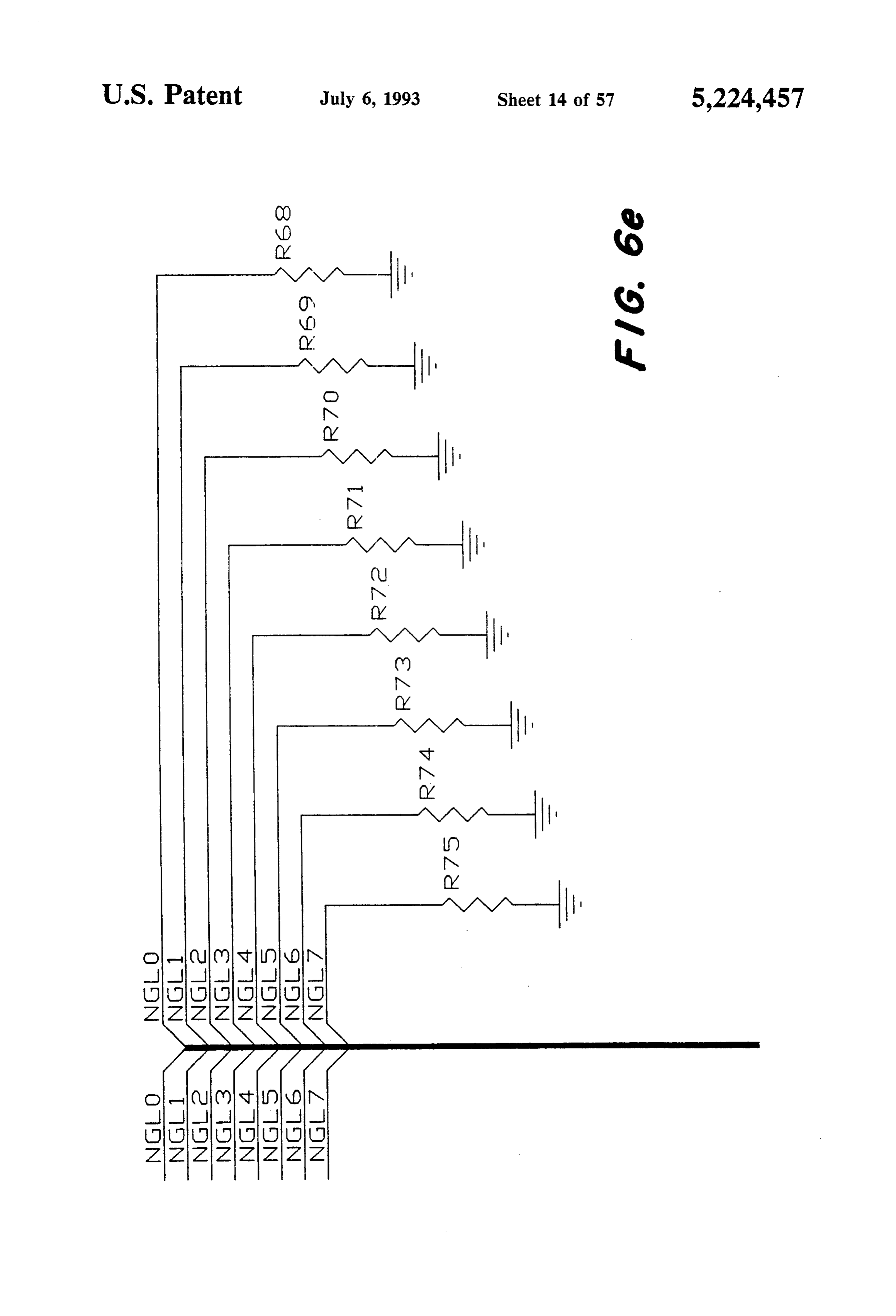
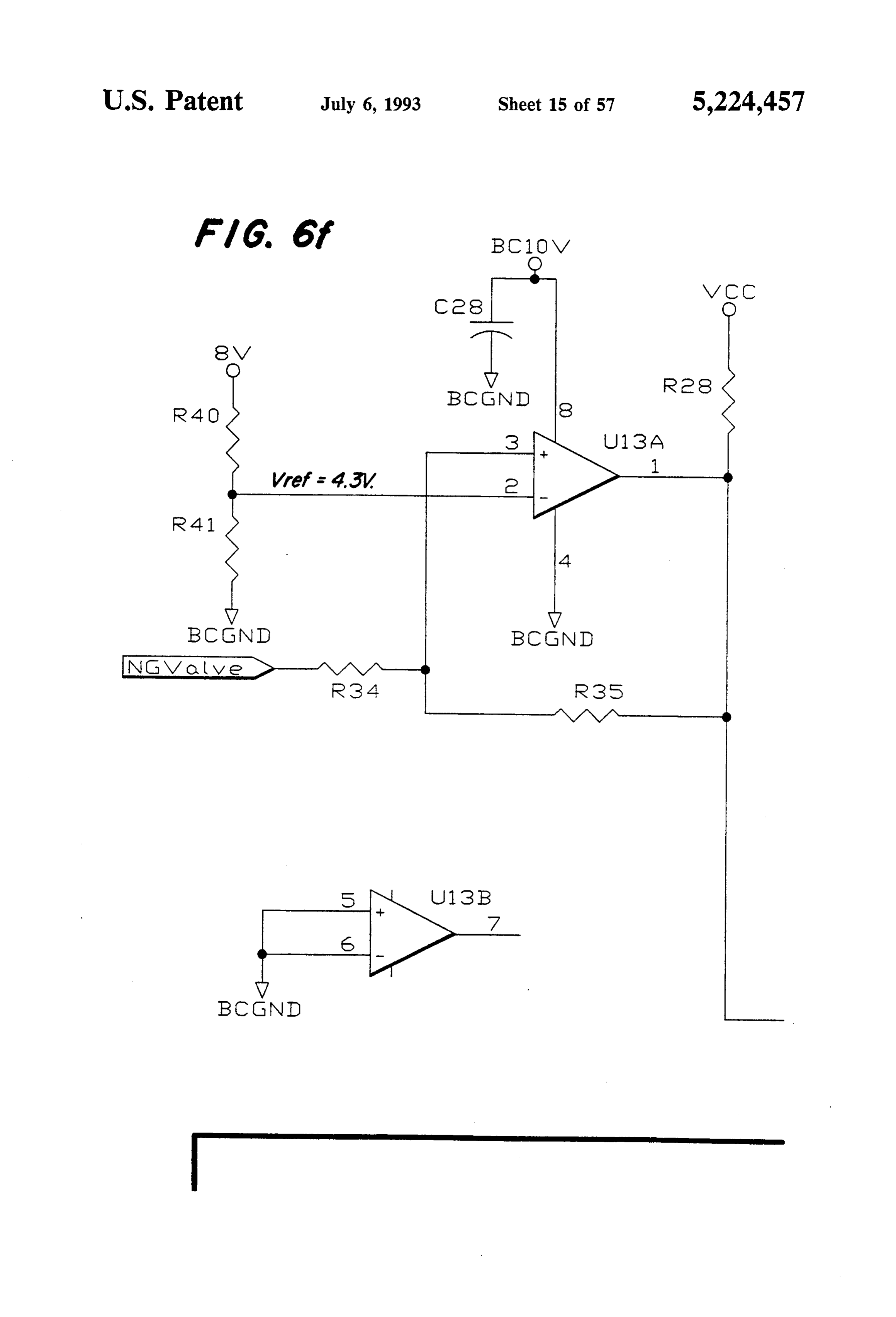
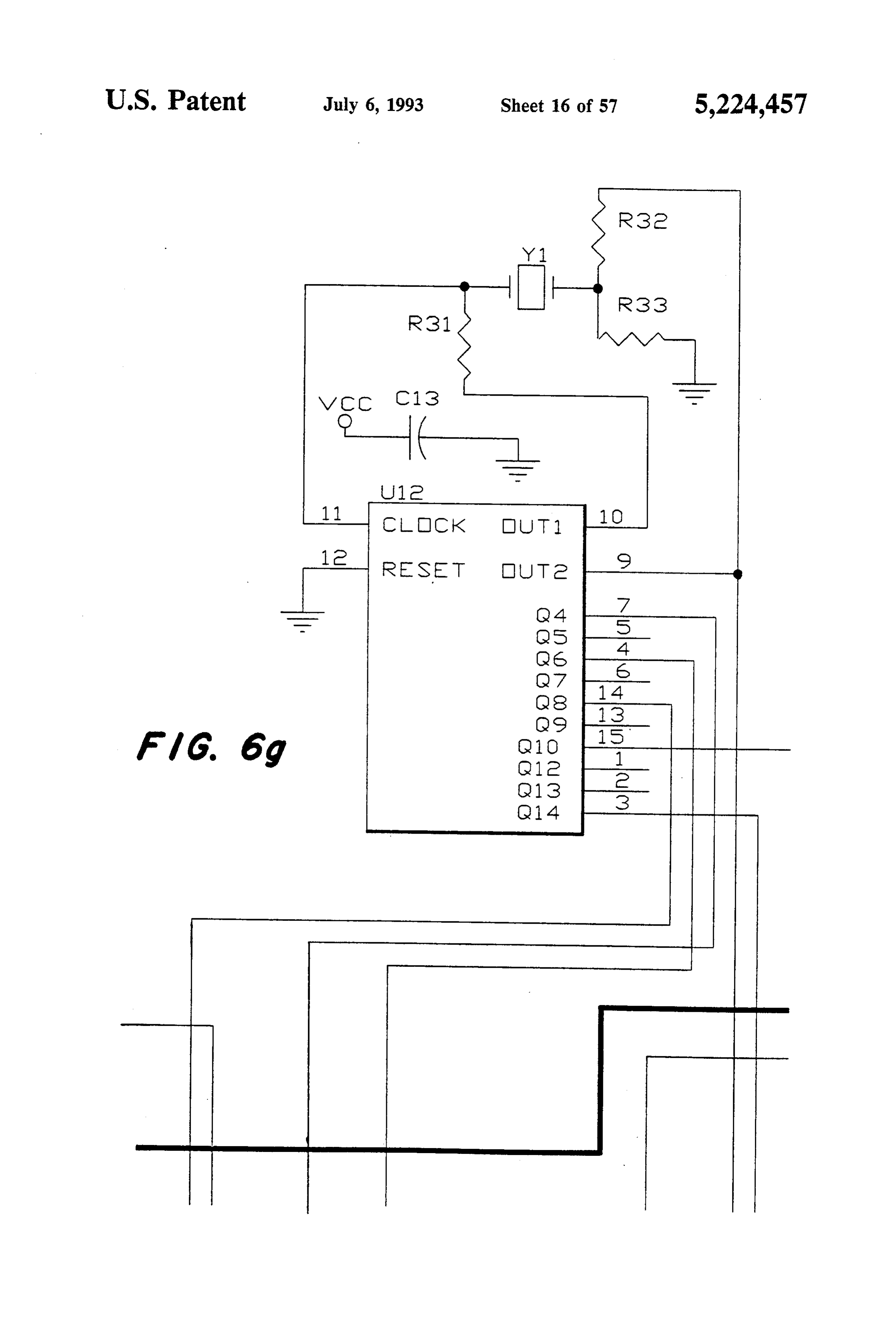
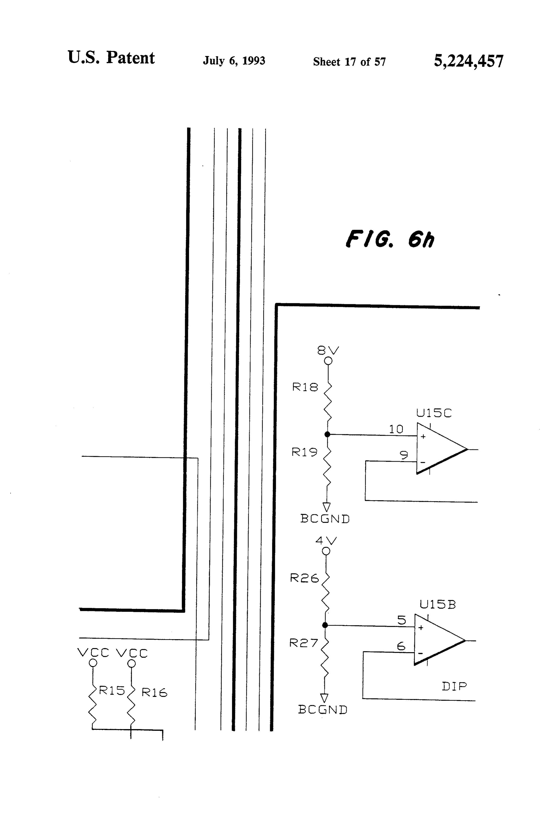
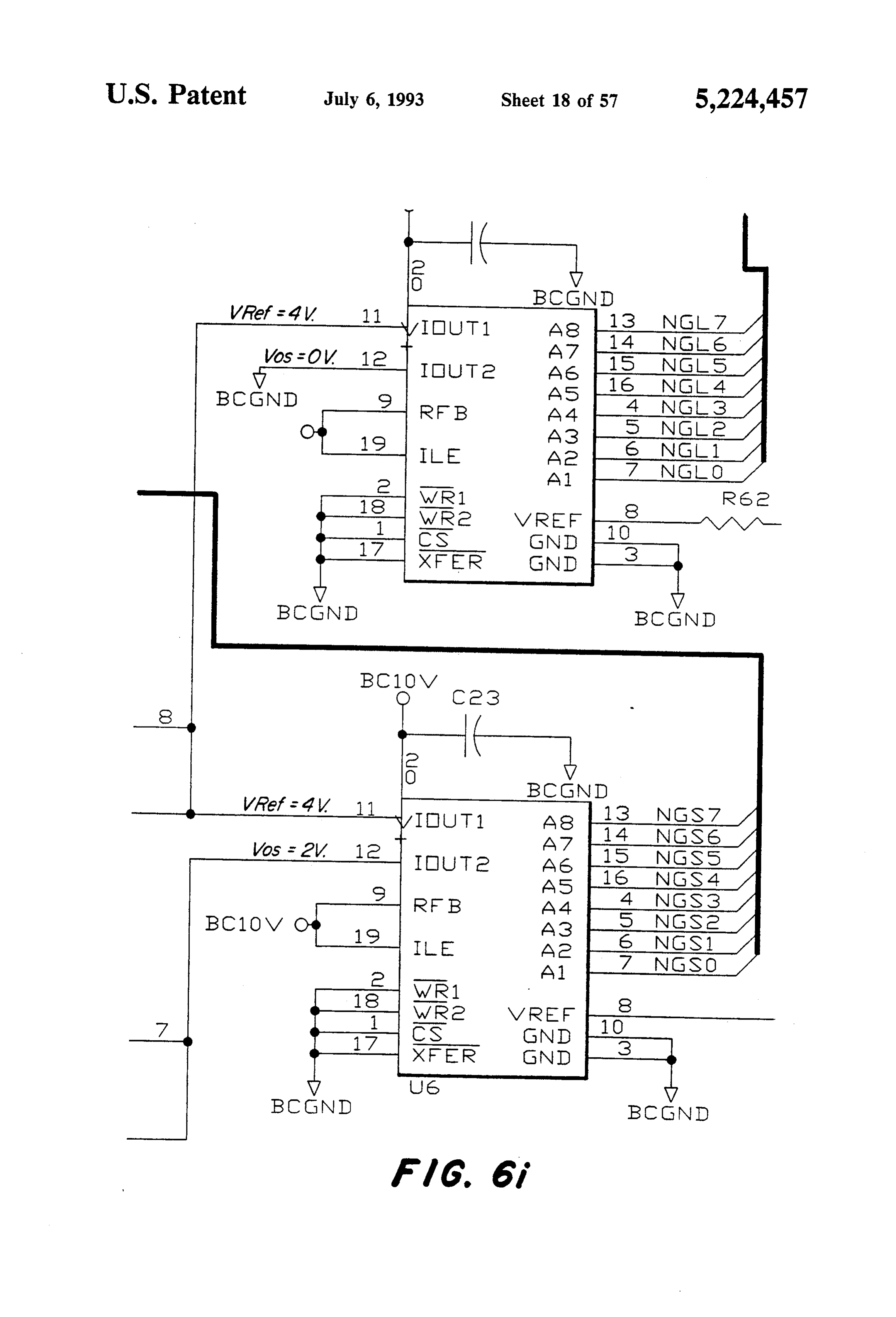
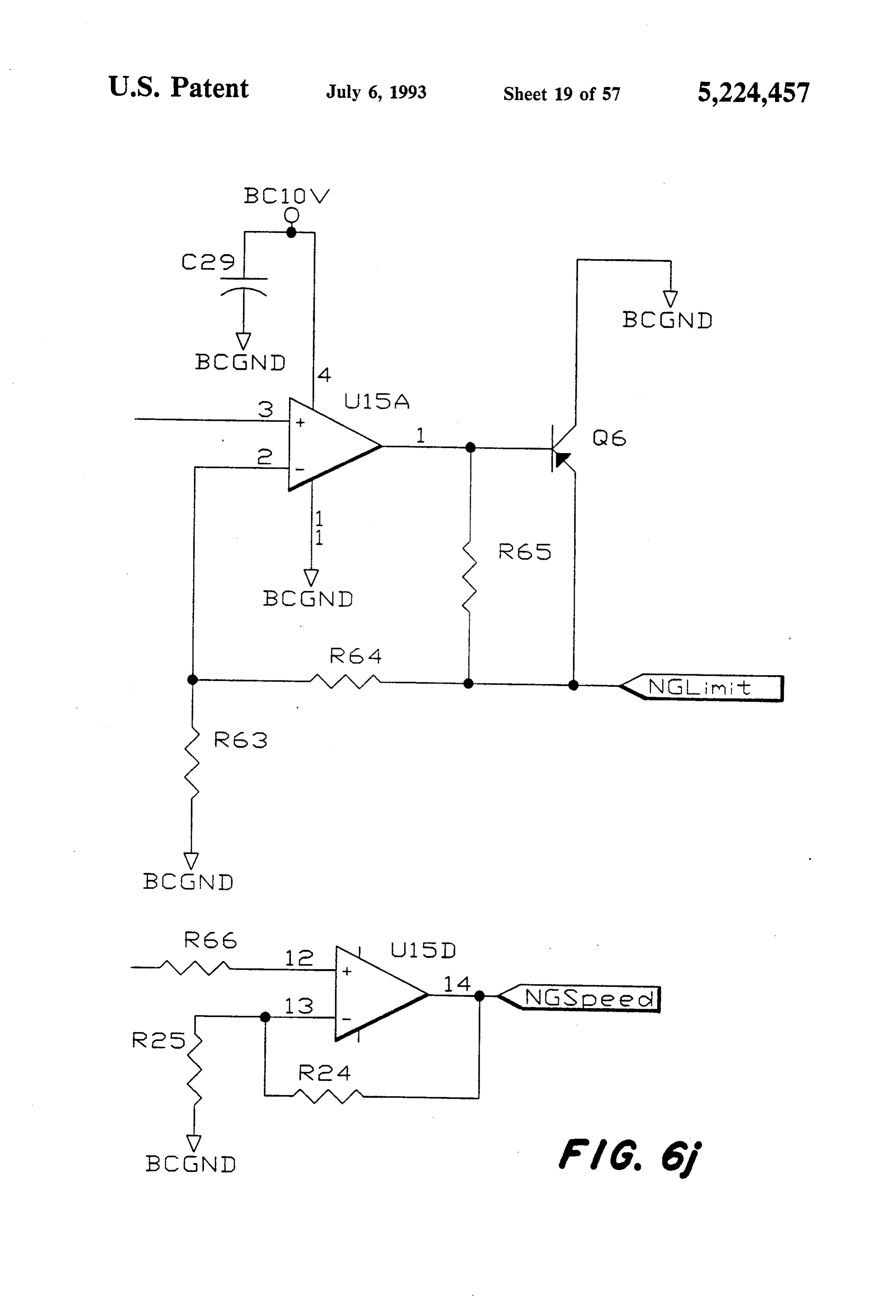
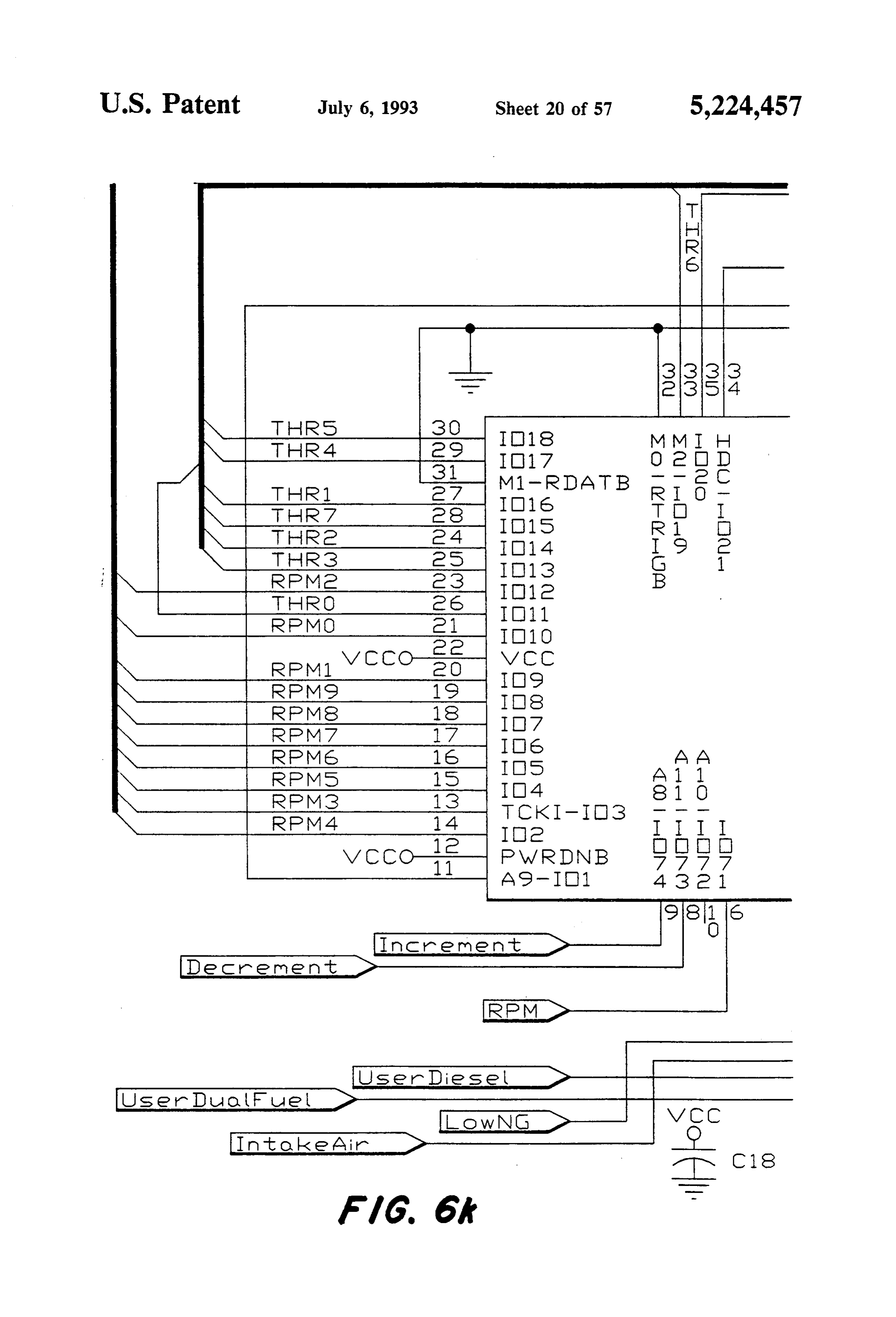
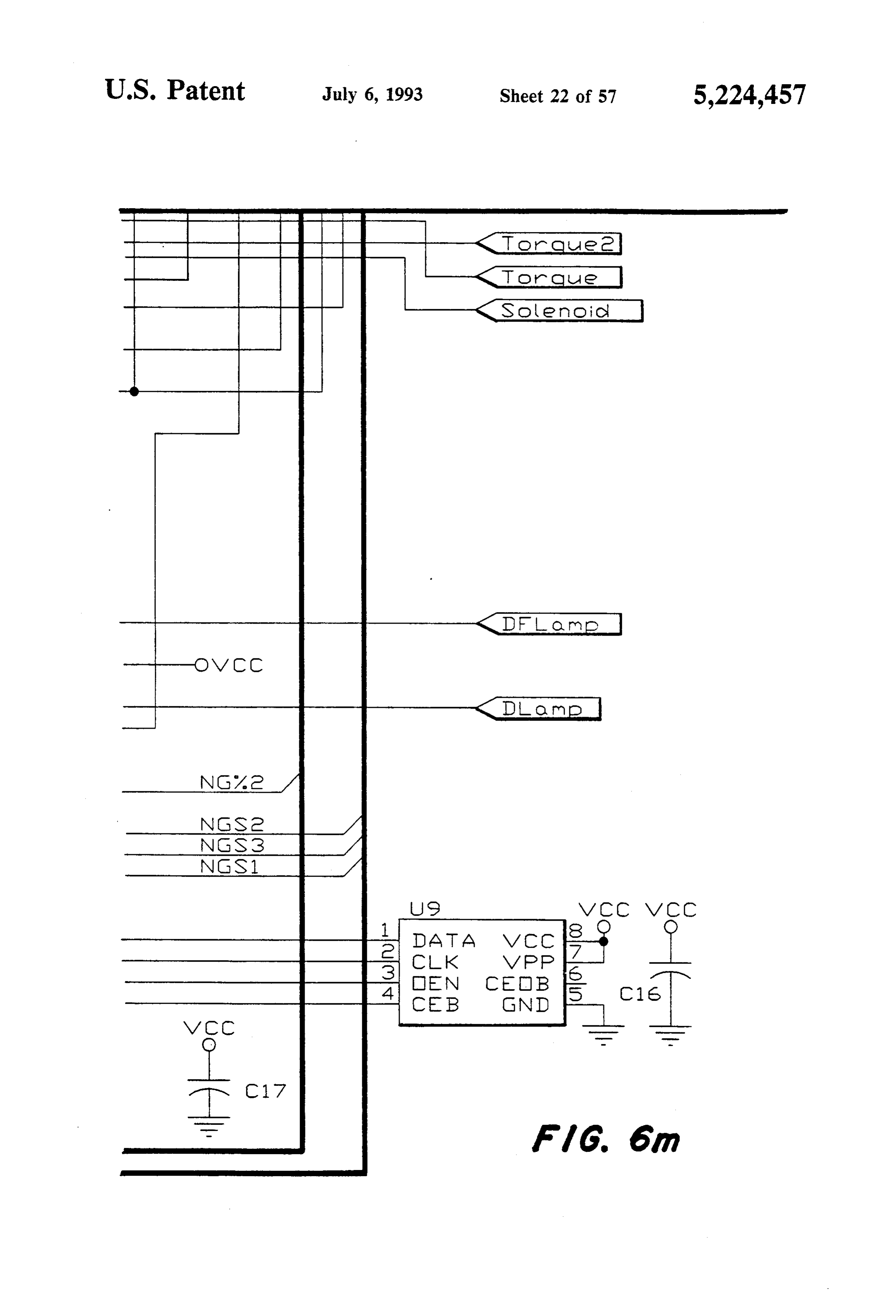
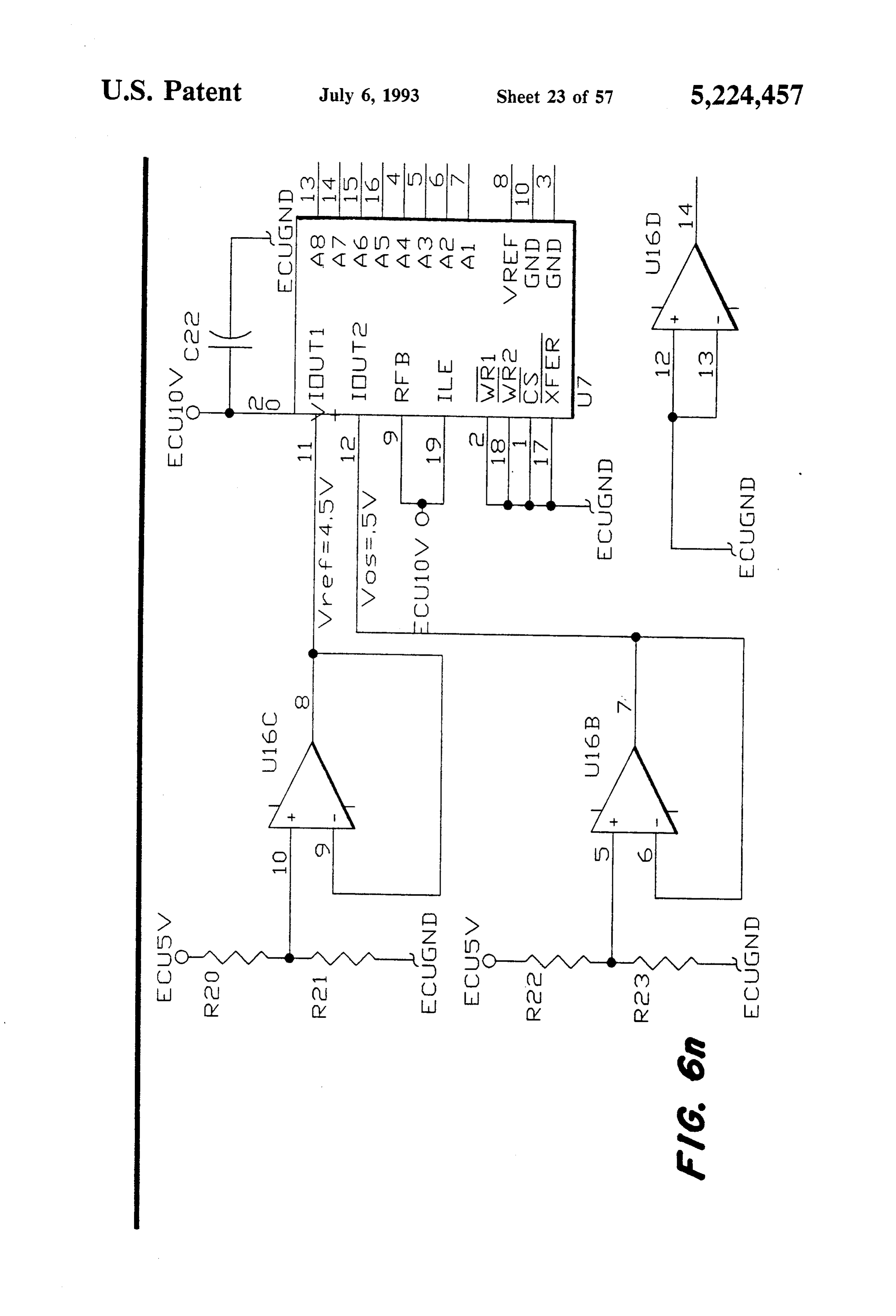
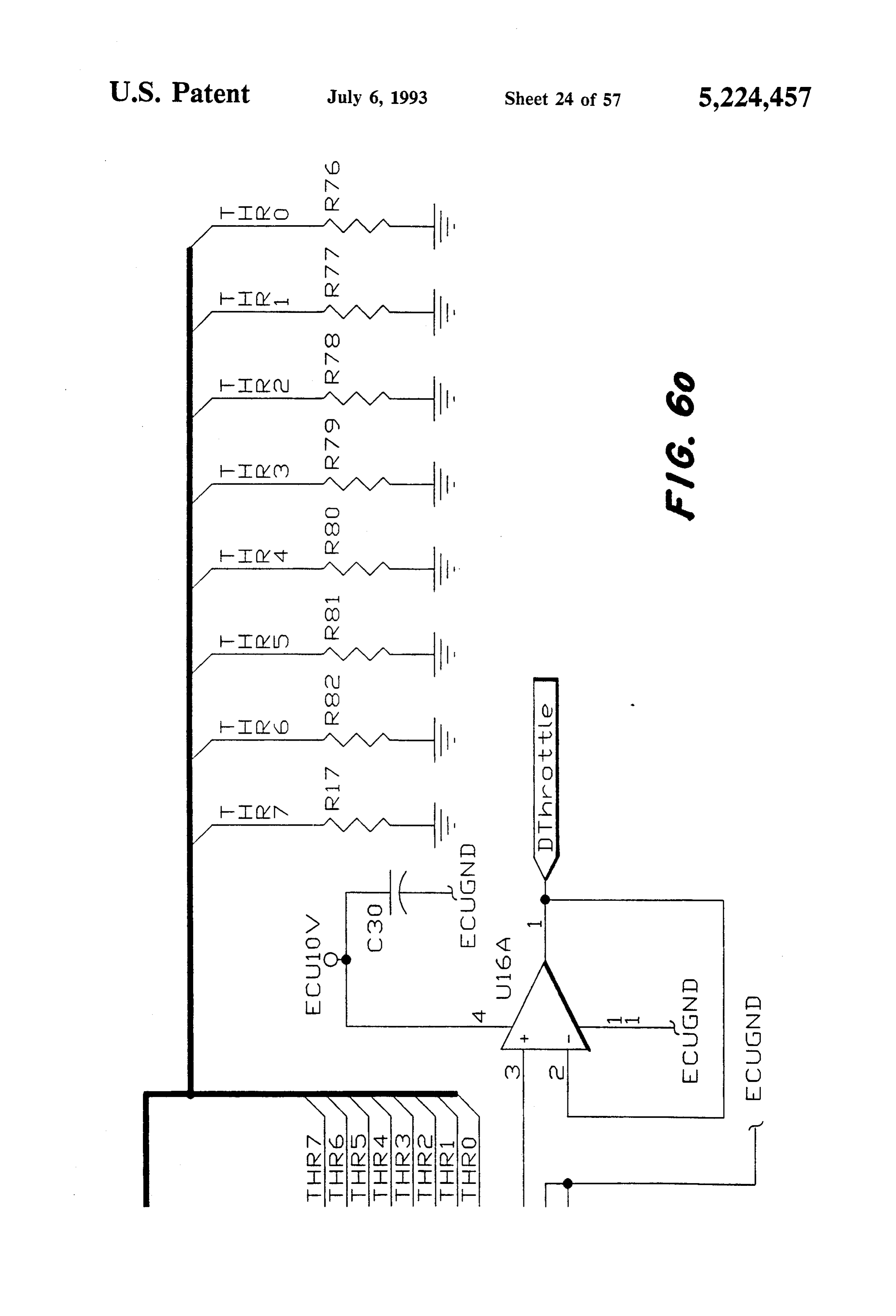
Another object of the present invention is to provide FIG. 6a shows the arrangement of FIGS. 6b-6o. a link controller which links together a production FIGS. 6b-6o are combined to form a circuit diagram mechanical/electronic diesel injection system with a illustrating the link controller control circuitry of the production stationary isochronous electronic natural present invention.
gas governing system. FIGS. 7a and 7b are circuit diagrams illustrating the Another object of the present invention is to provide link controller output conditioning circuitry of the pres such a link controller which incorporates safety shut 45 ent invention.
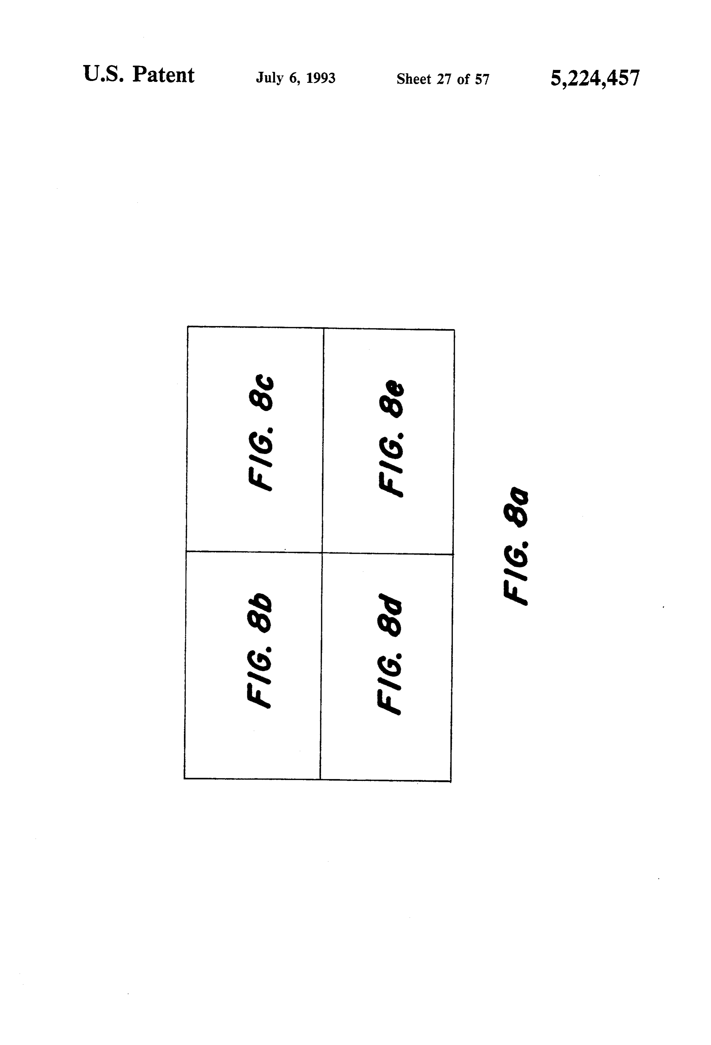
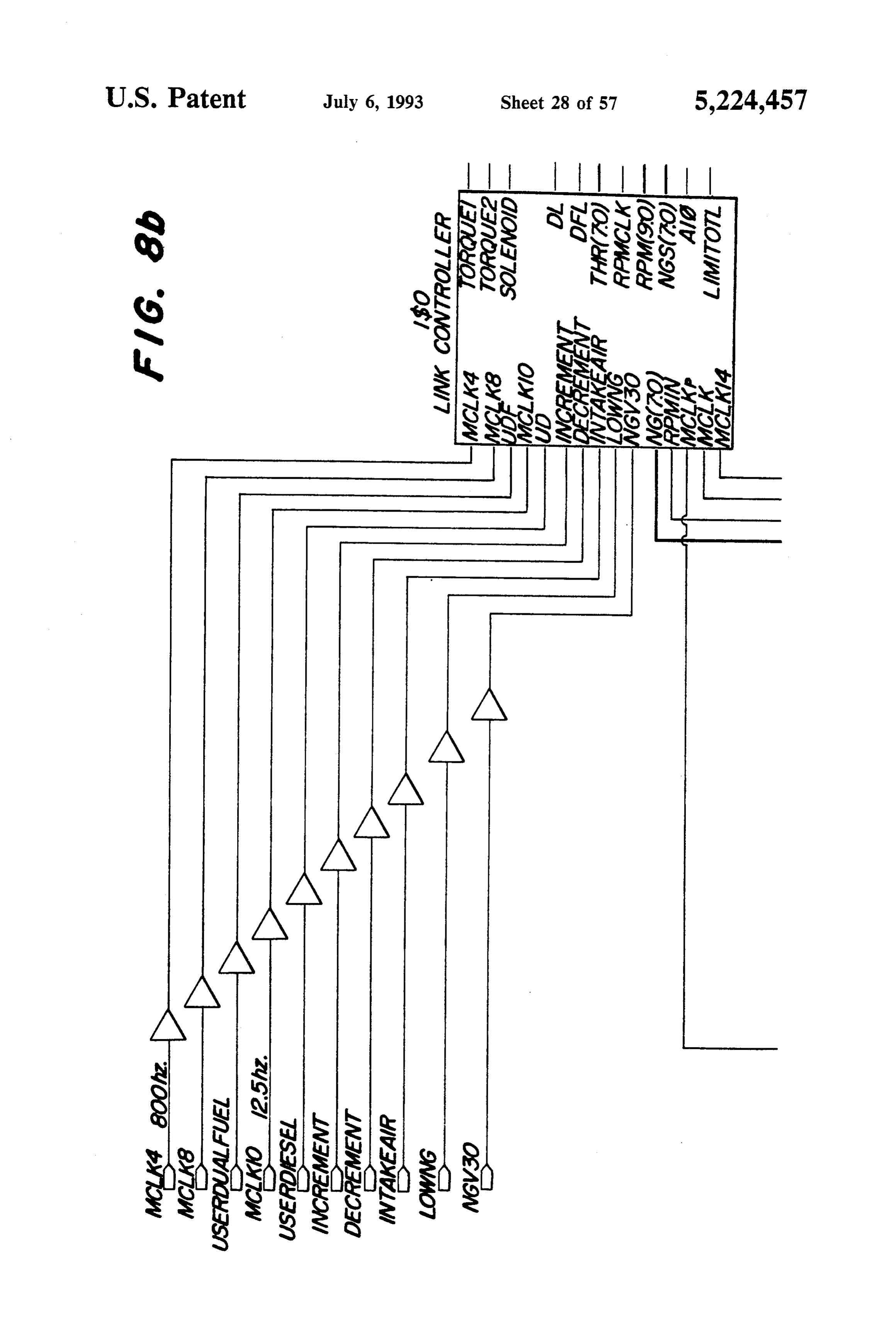
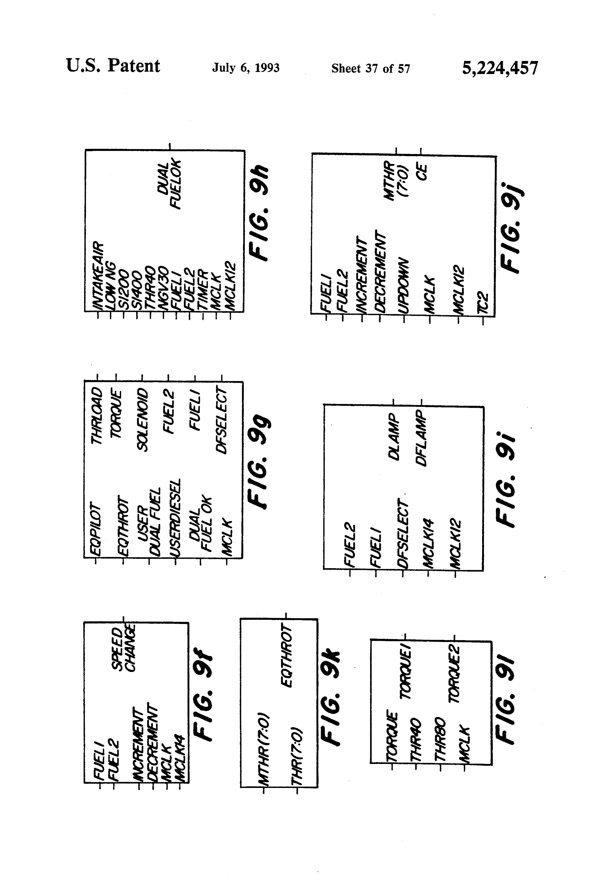
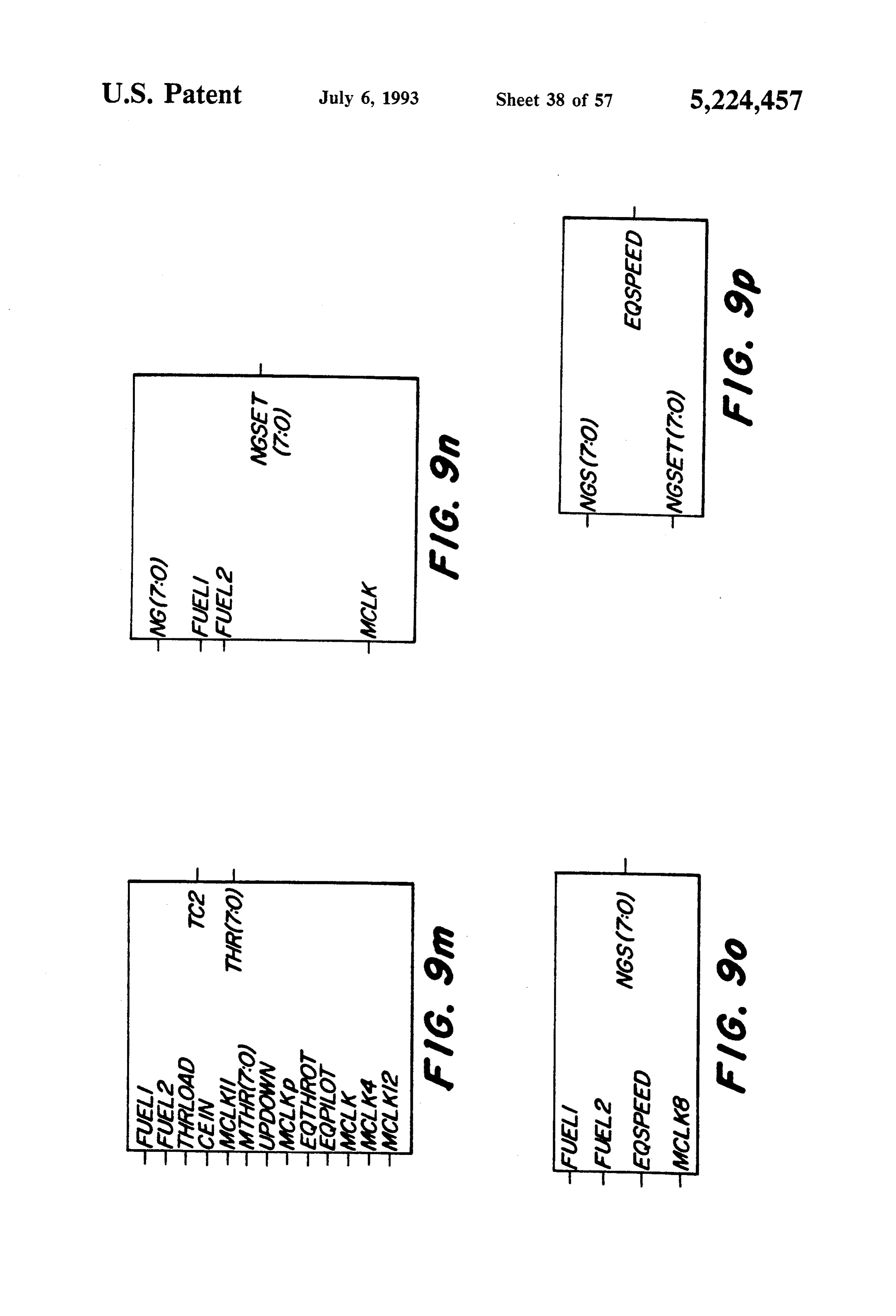
down features, and which controls operation on either FIG. 8a shows the arrangement of FIGS. 8b-8e. diesel or dual fuel, depending on sensed input condi FIGS. 8b-8e are combined to form a top level sche tions. matic diagram illustrating the Programmable Gate Another object of the present invention is to provide Array of the link controller of the present invention. such a link controller which allows maximum use of 50 FIGS. 9a-9p are combined to form a lower level natural gas as a fuel for a diesel engine, ensuring that the Schematic diagram illustrating the Programmable Gate engine is operated within accepted temperature and Array design of the link controller element ISO of pressure limits. FIGS. 8a-8e.
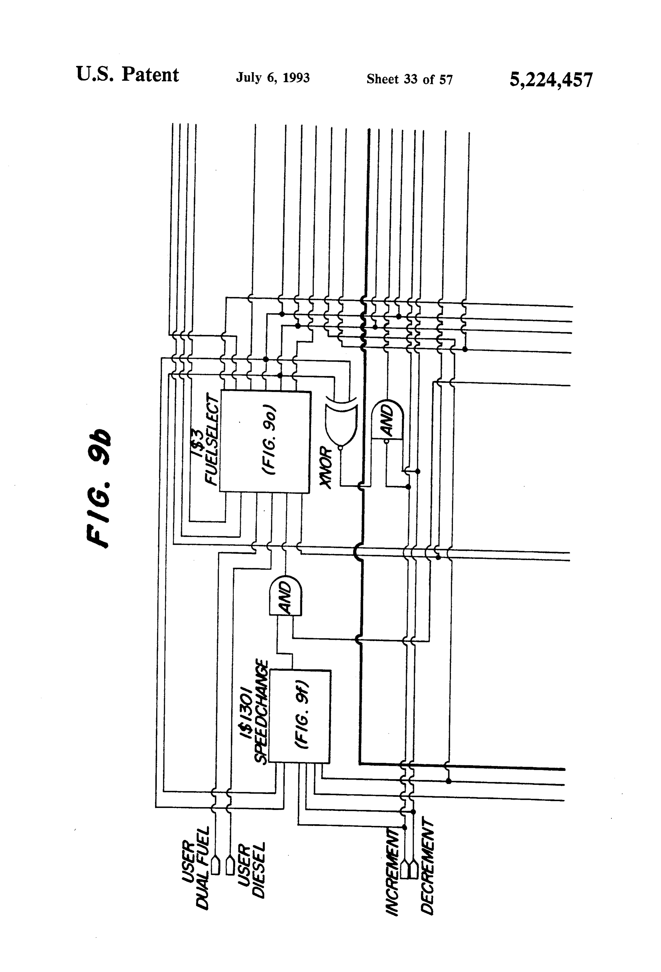
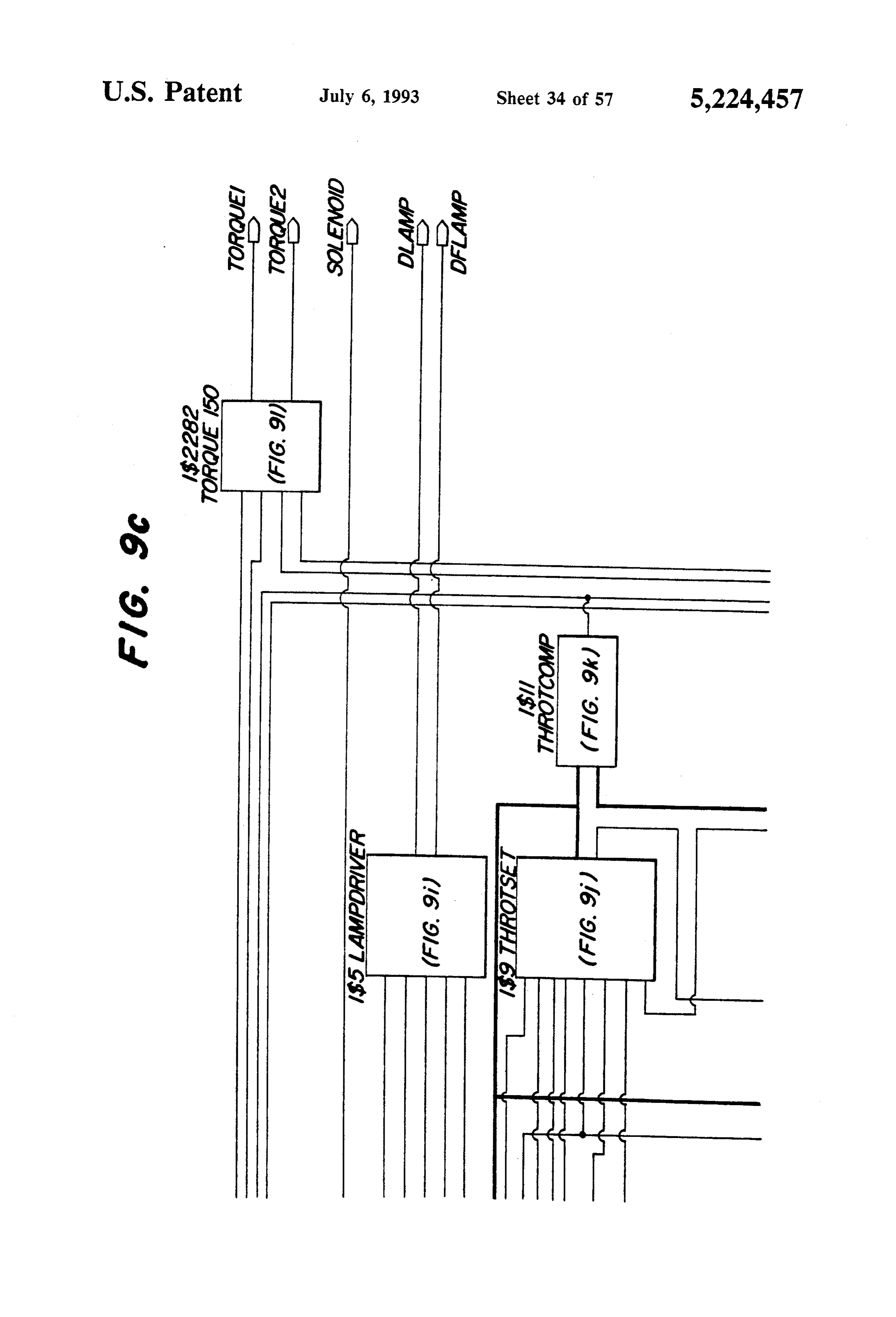
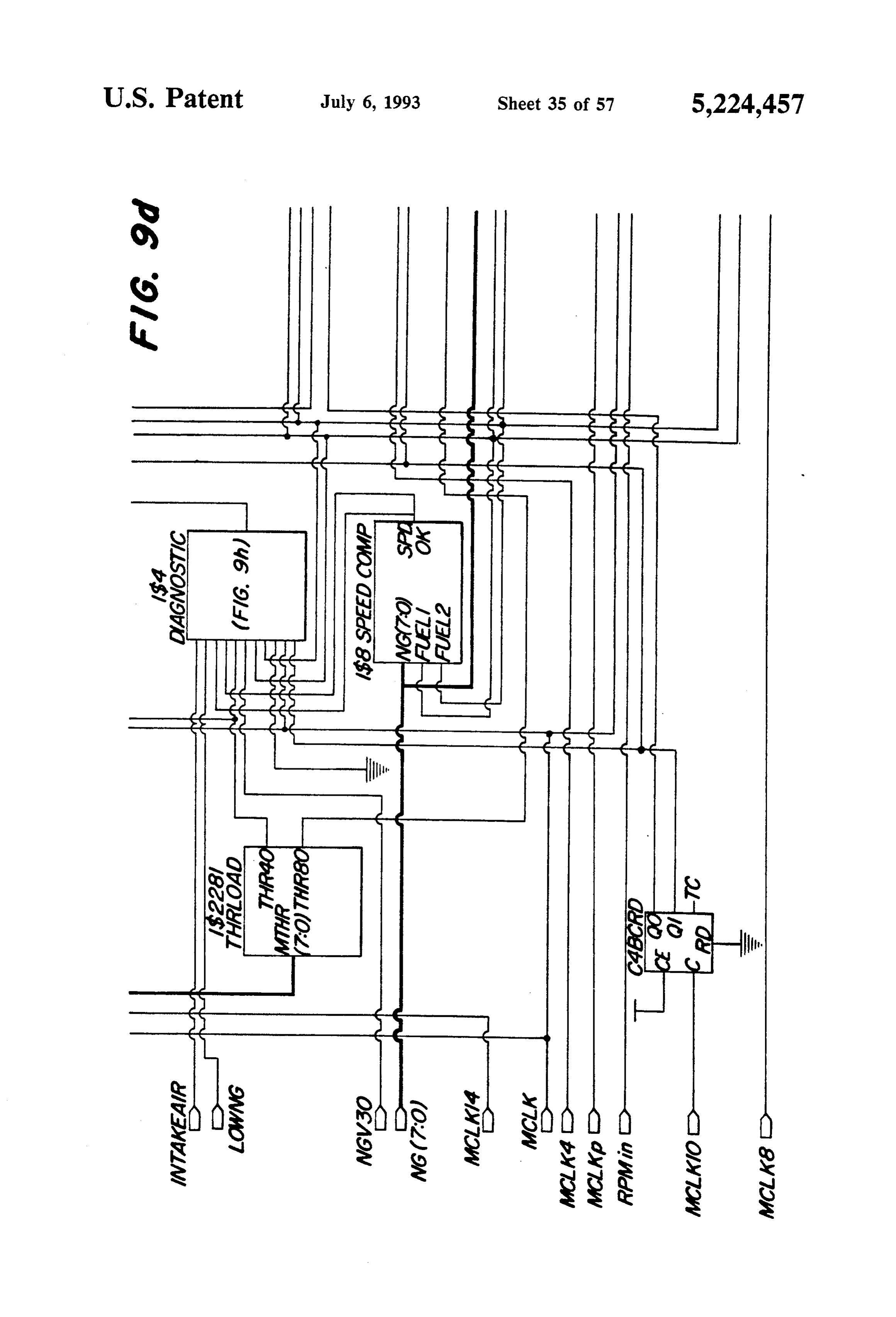
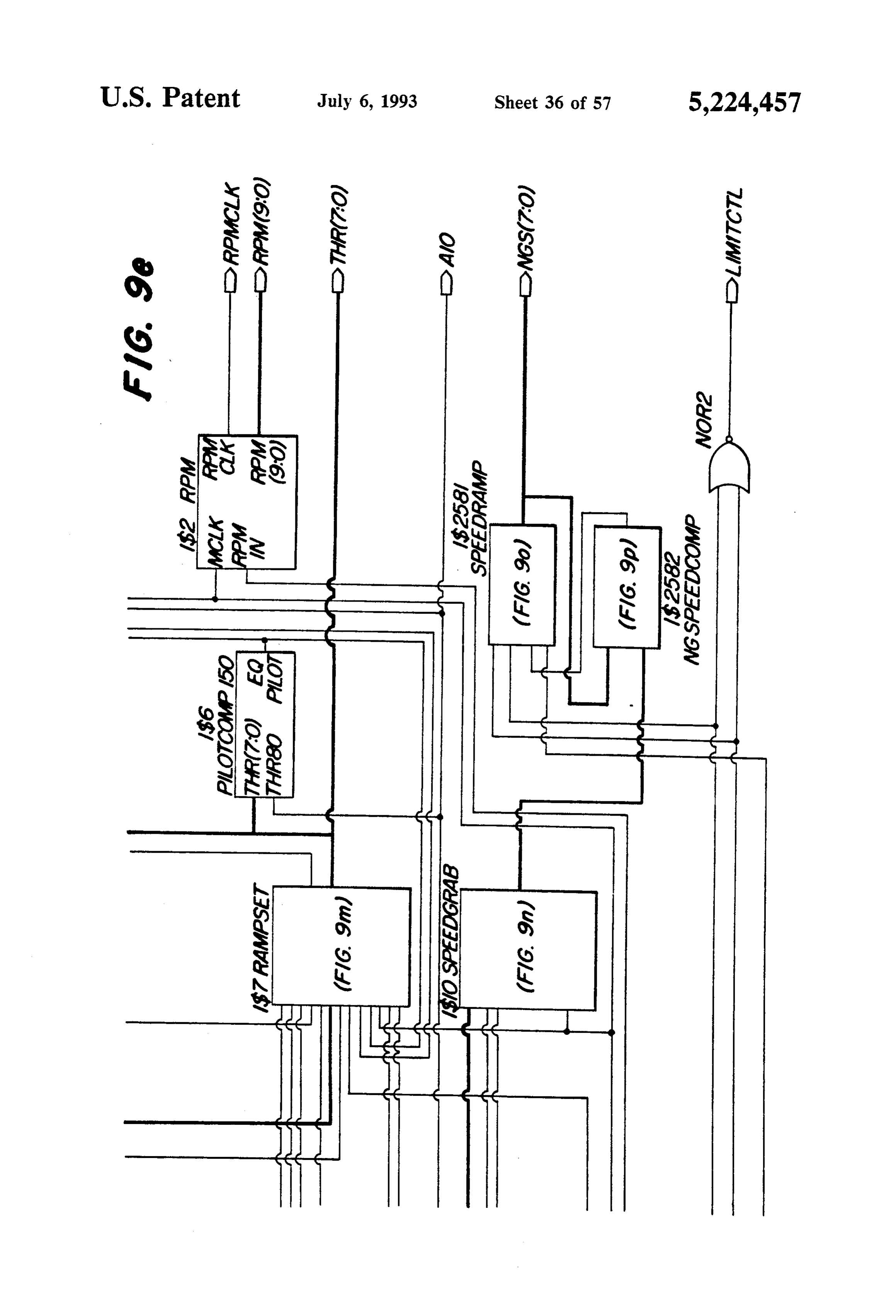
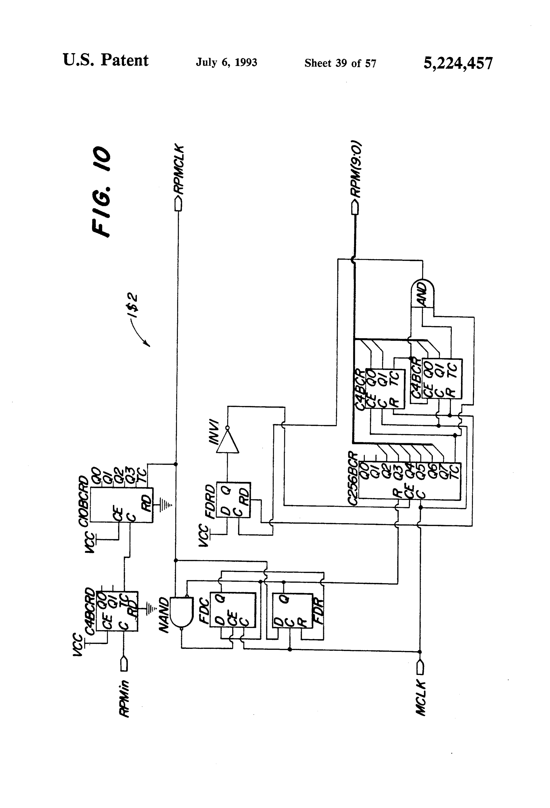
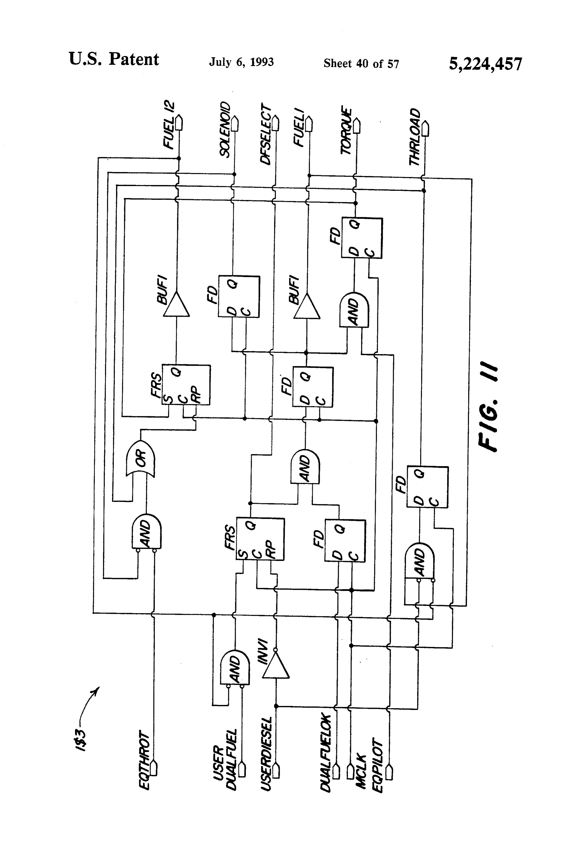
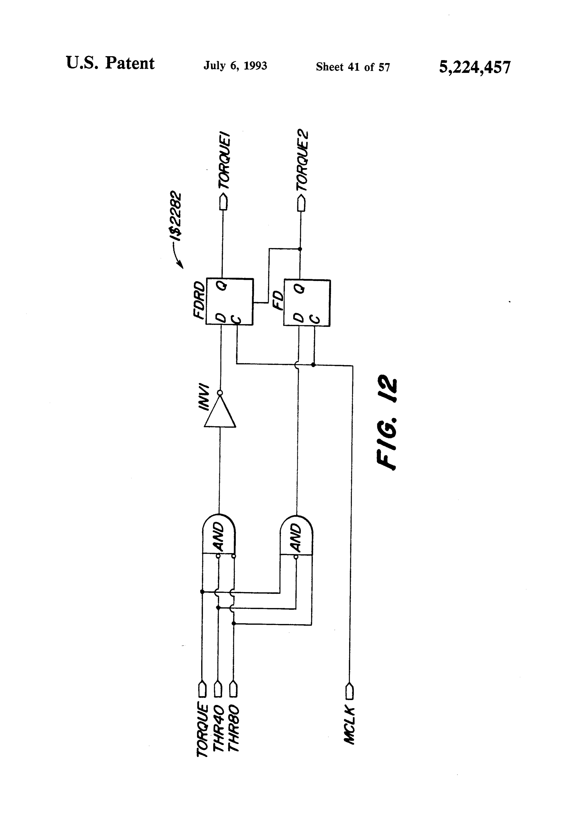
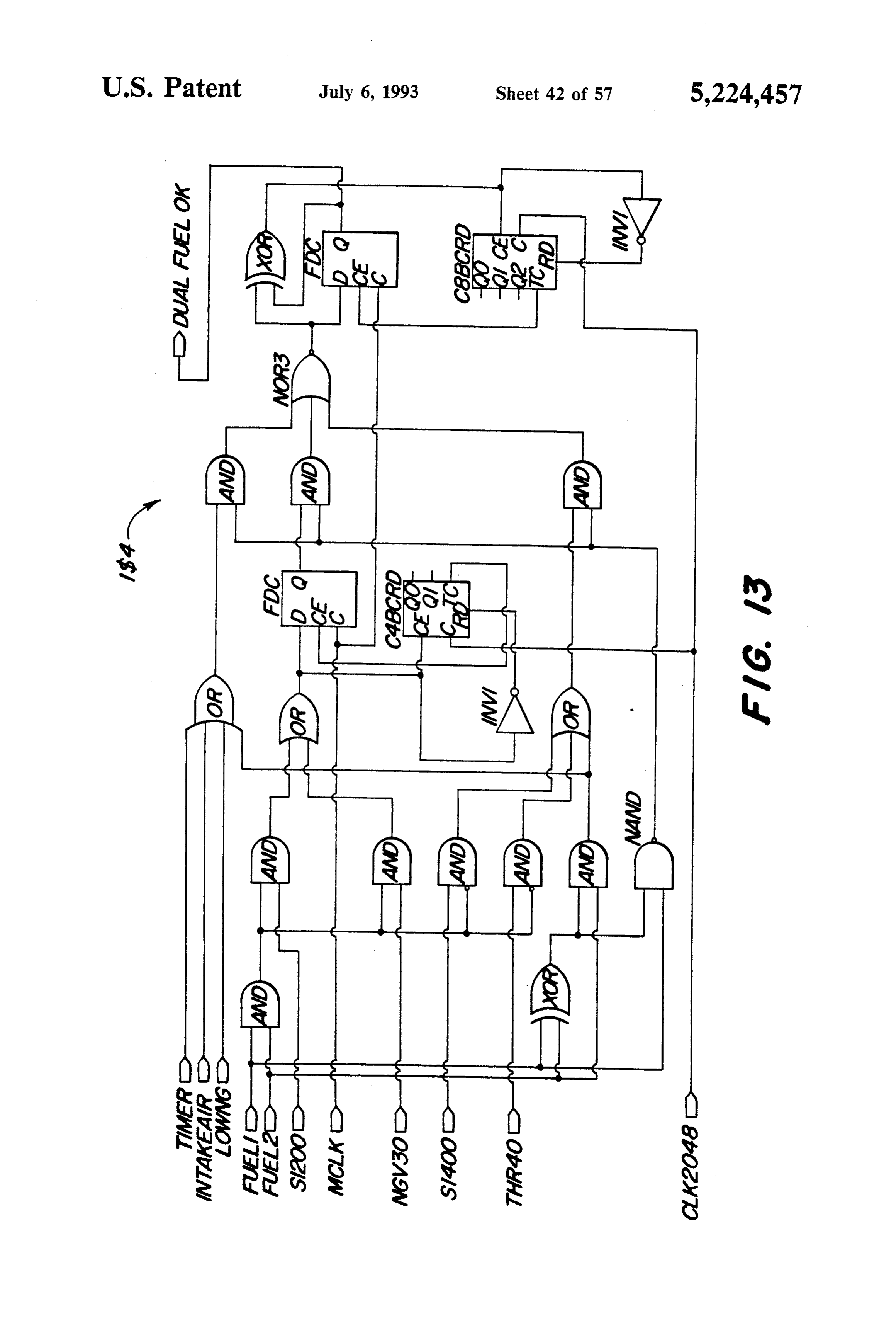
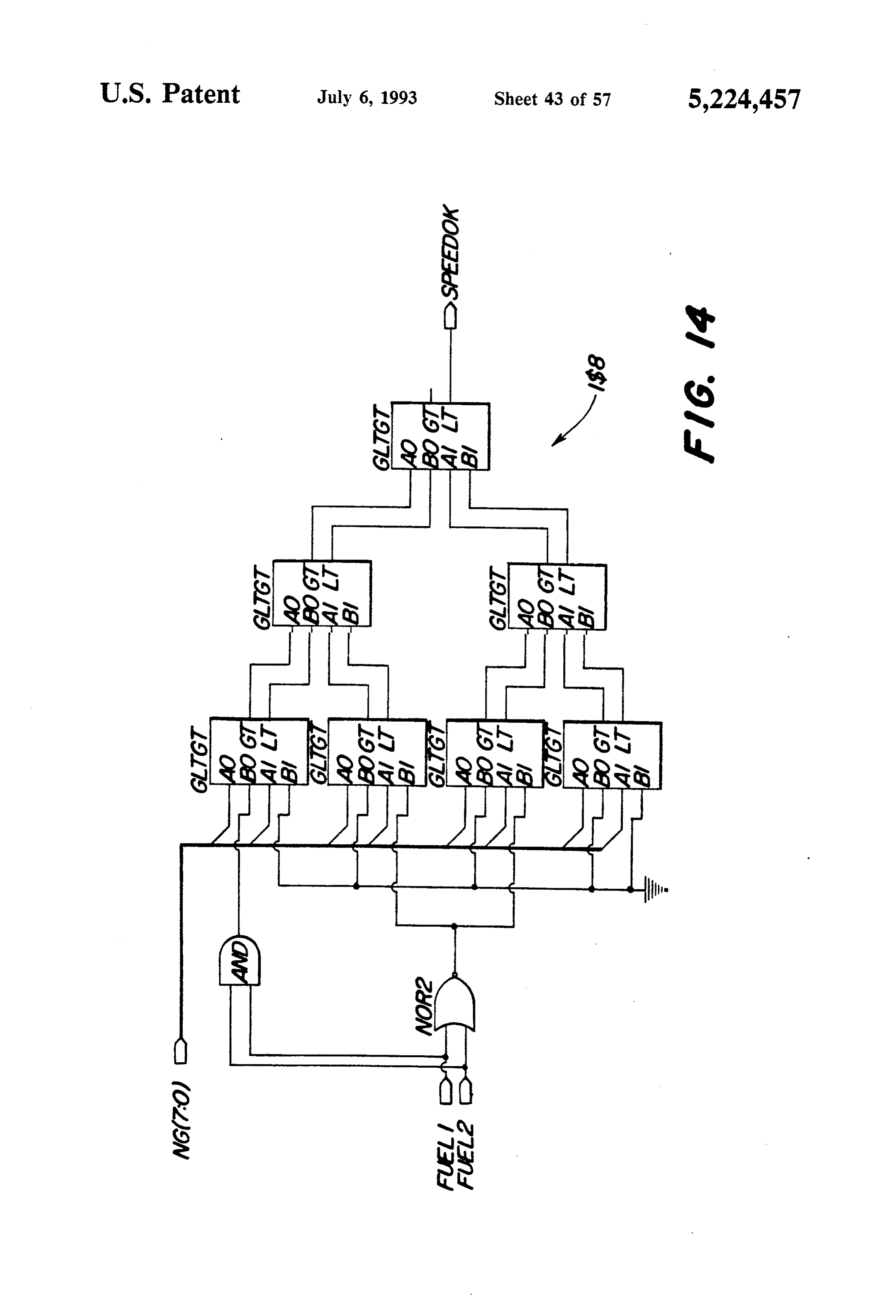
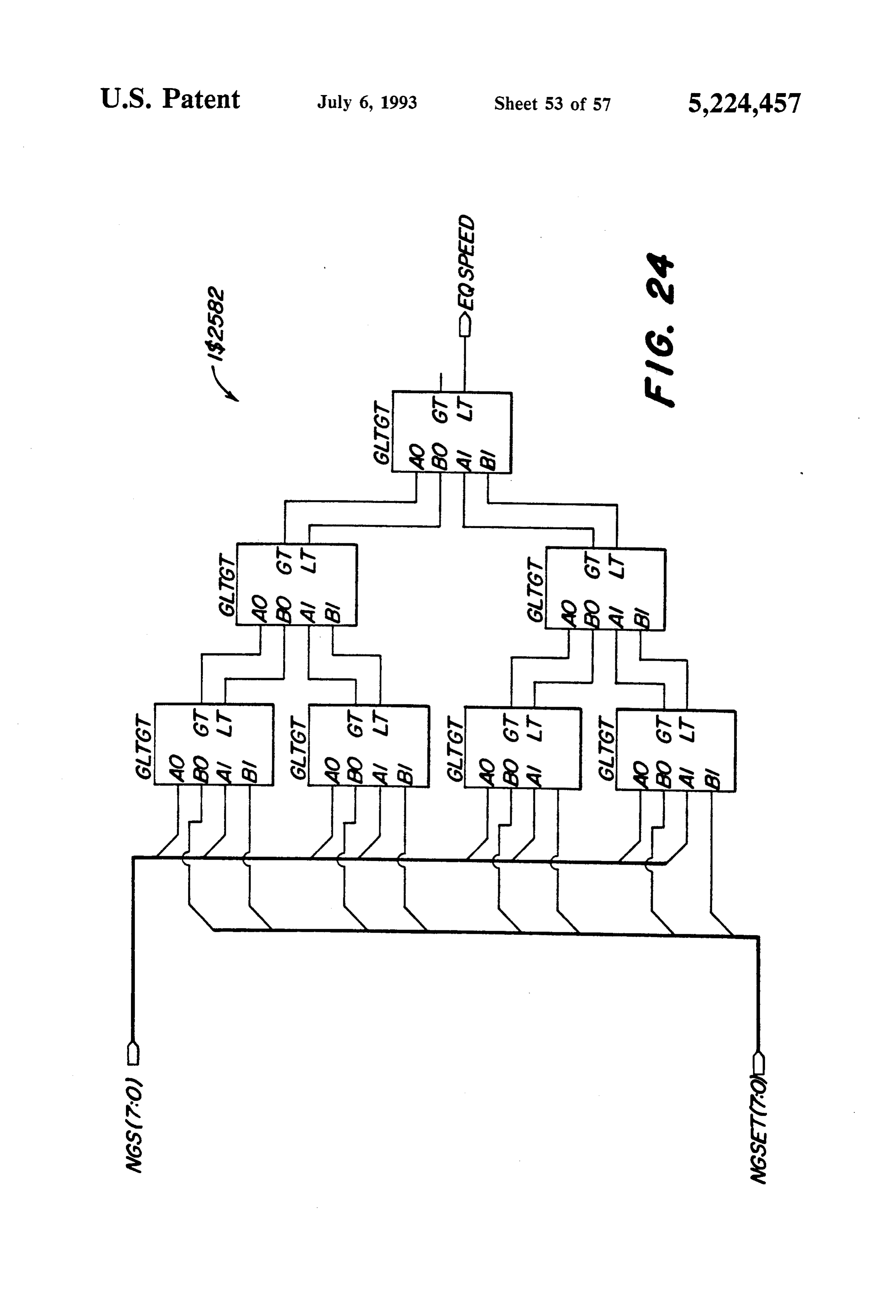
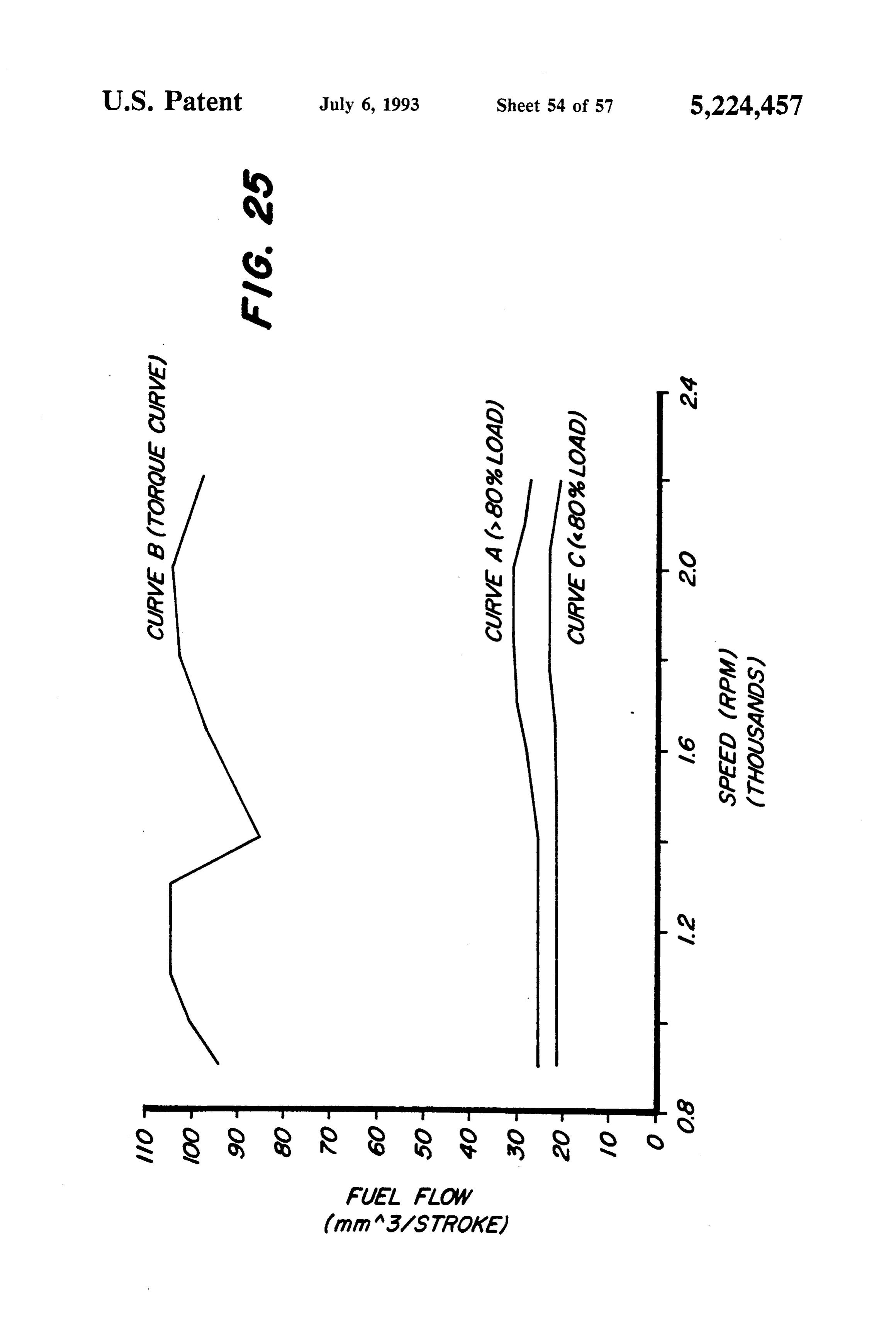
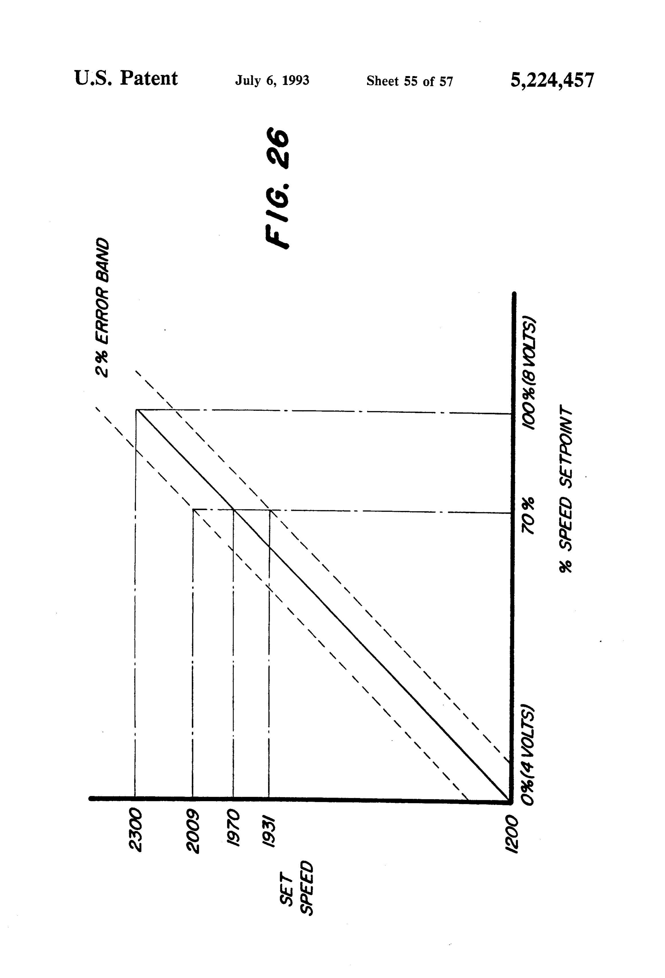
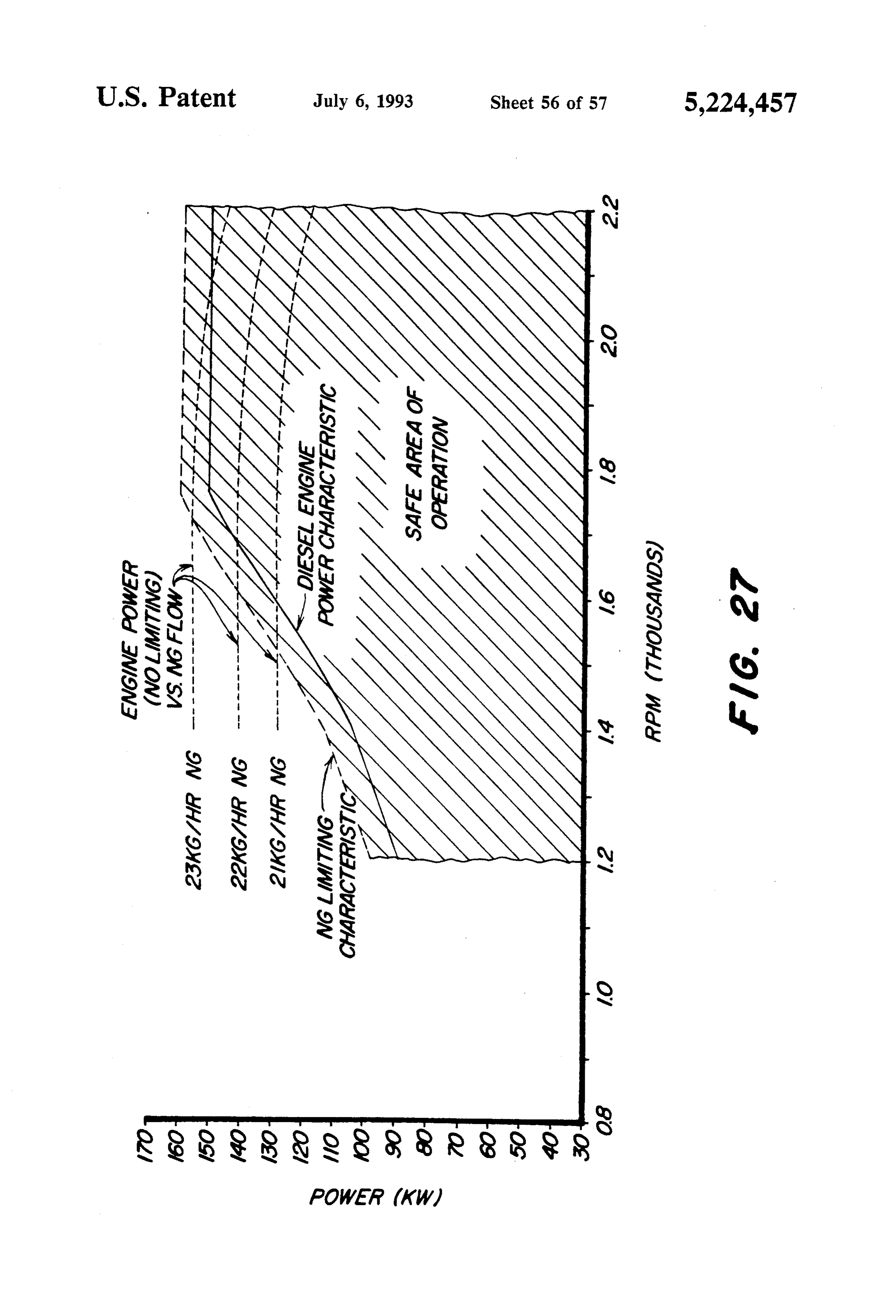
These and other objects are achieved by the present FIG. 10 is a detailed schematic diagram illustrating invention wherein a dual fuel system for a diesel engine 55 the Programmable Gate Array design of the RPM cal includes a liquid (diesel) fuel injection system controlled culation circuitry (element IS2) of FIG.9e. by an engine electronic control unit (ECU) and a source FIG. 11 is a detailed schematic diagram illustrating of gaseous fuel such as natural gas. A metering valve the Programmable Gate Array design of the fuel select and a mixer controls introduction of gaseous fuel from circuit (element IS3) of FIGS. 9b and 9o. the gaseous fuel source into combustion air for the en FIG. 12 is a detailed schematic diagram illustrating gine. An electronic governor controls the metering the Programmable Gate Array design of the torque valve and a link controller coordinates operation of the select circuit (element IS2282) of FIGS. 9c and 91. ECU and the governor. Preferably, a regulator regu FIG. 13 is a detailed schematic diagram illustrating lates the pressure of gaseous fuel supplied to the meter the Programmable Gate Array design of the diagnostics ing valve. A shut-off valve controls communication of 65 circuit (element IS4) of FIGS. 9d and 9h. gaseous fuel between the source and the regulator. The FIG. 14 is a detailed schematic diagram illustrating link controller also controls the shut-off valve as a func the Programmable Gate Array design of the engine tion of sensed conditions. For example, a pressure sen speed comparator circuit (element IS8) of FIG. 9d.
Page 60
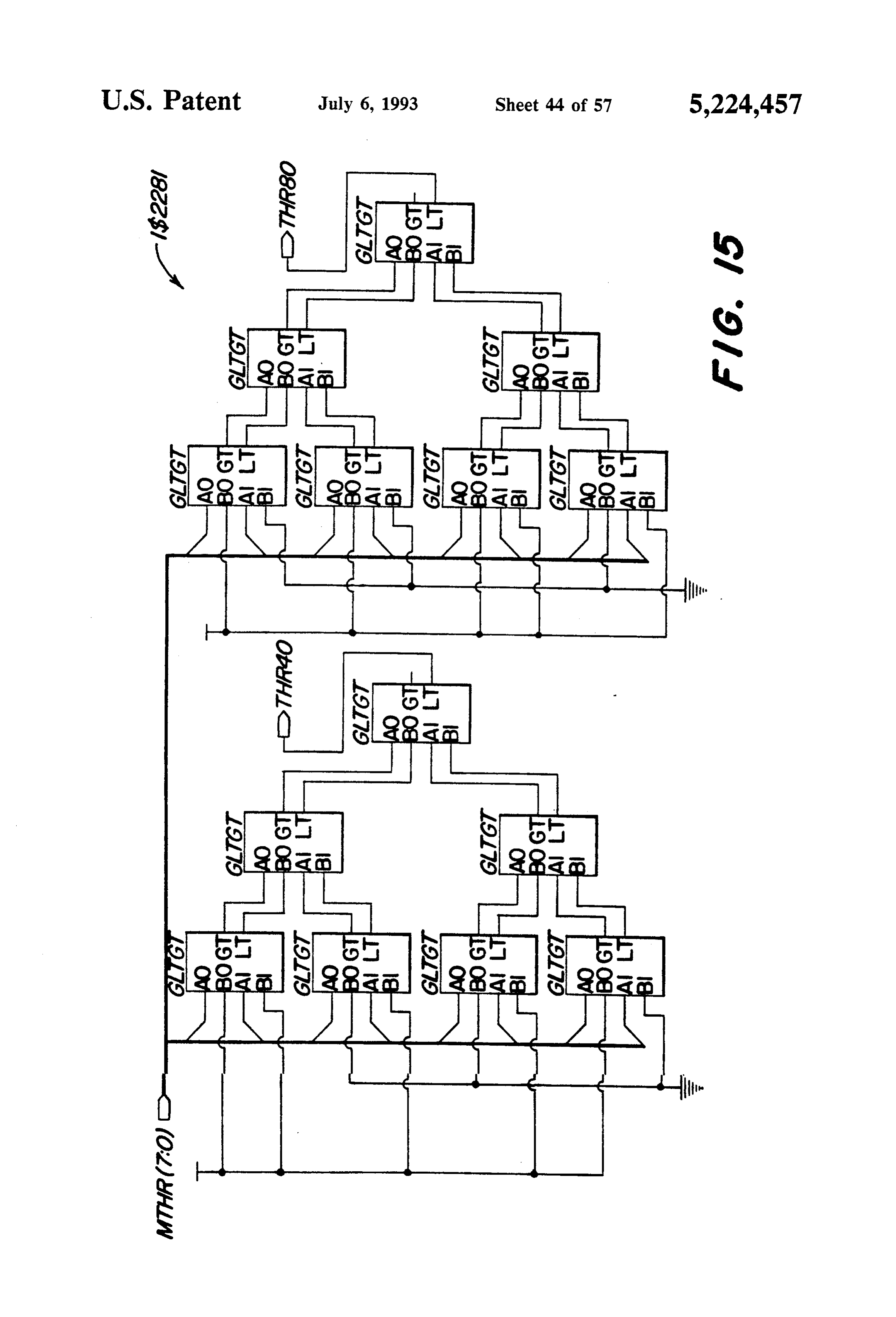
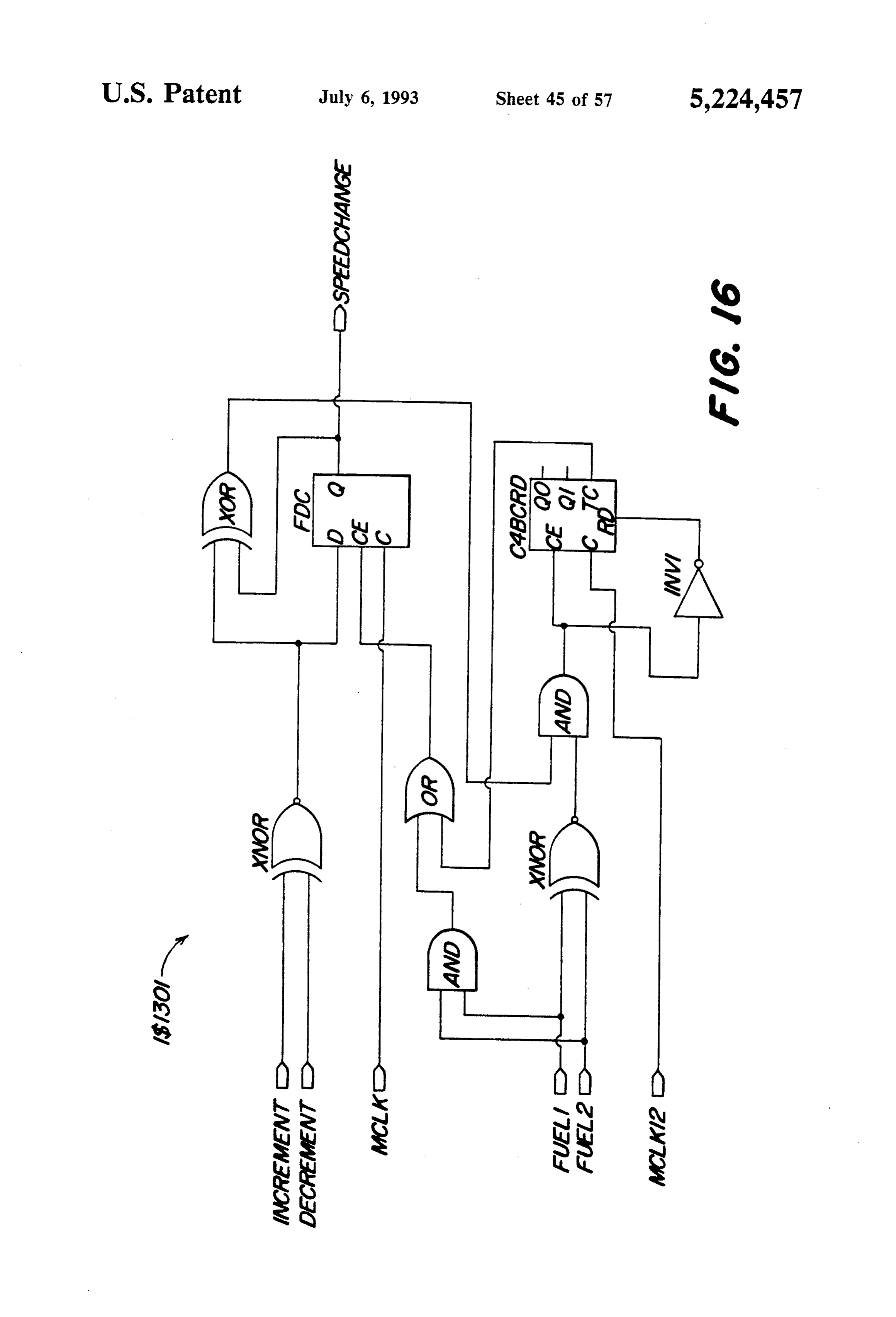
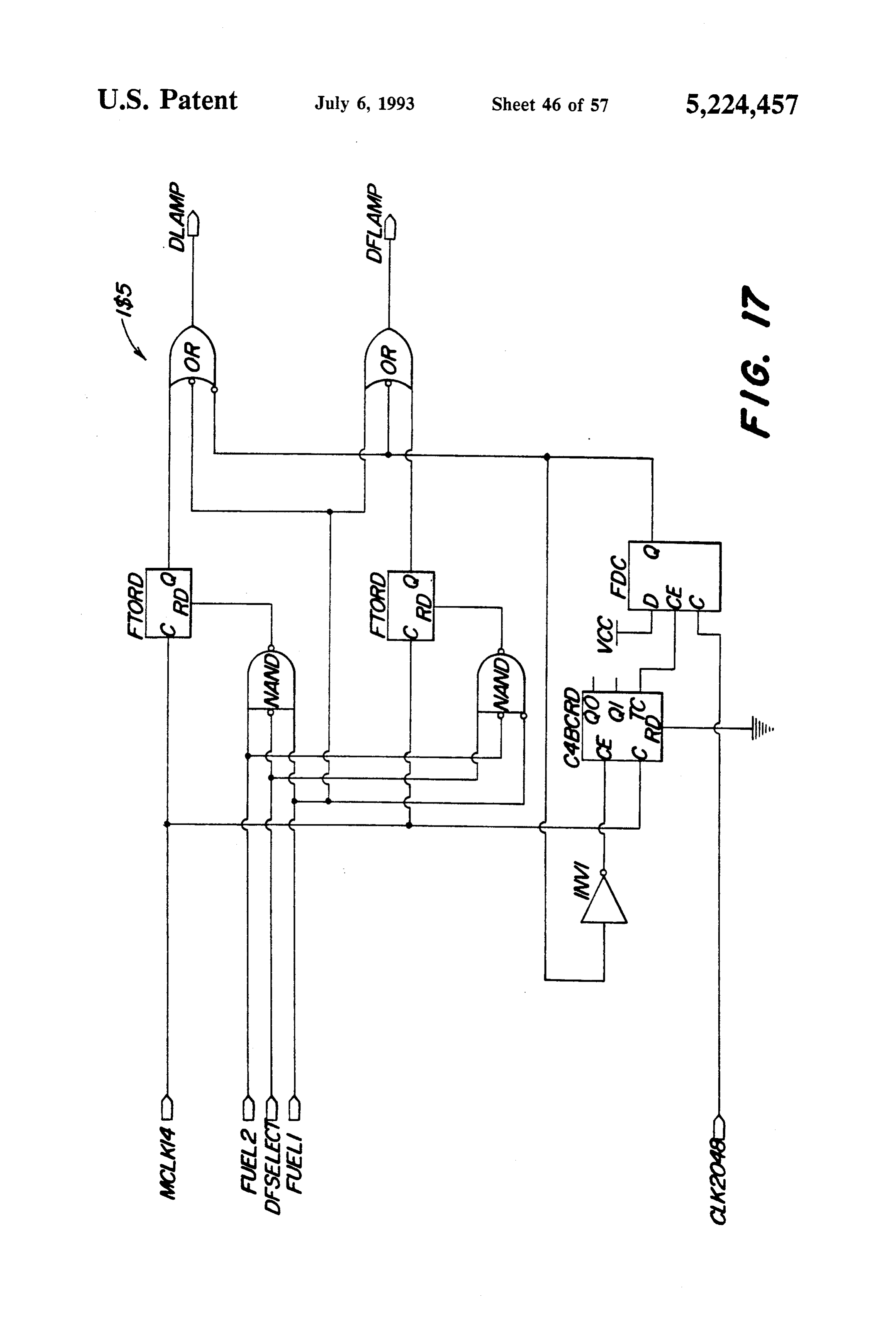
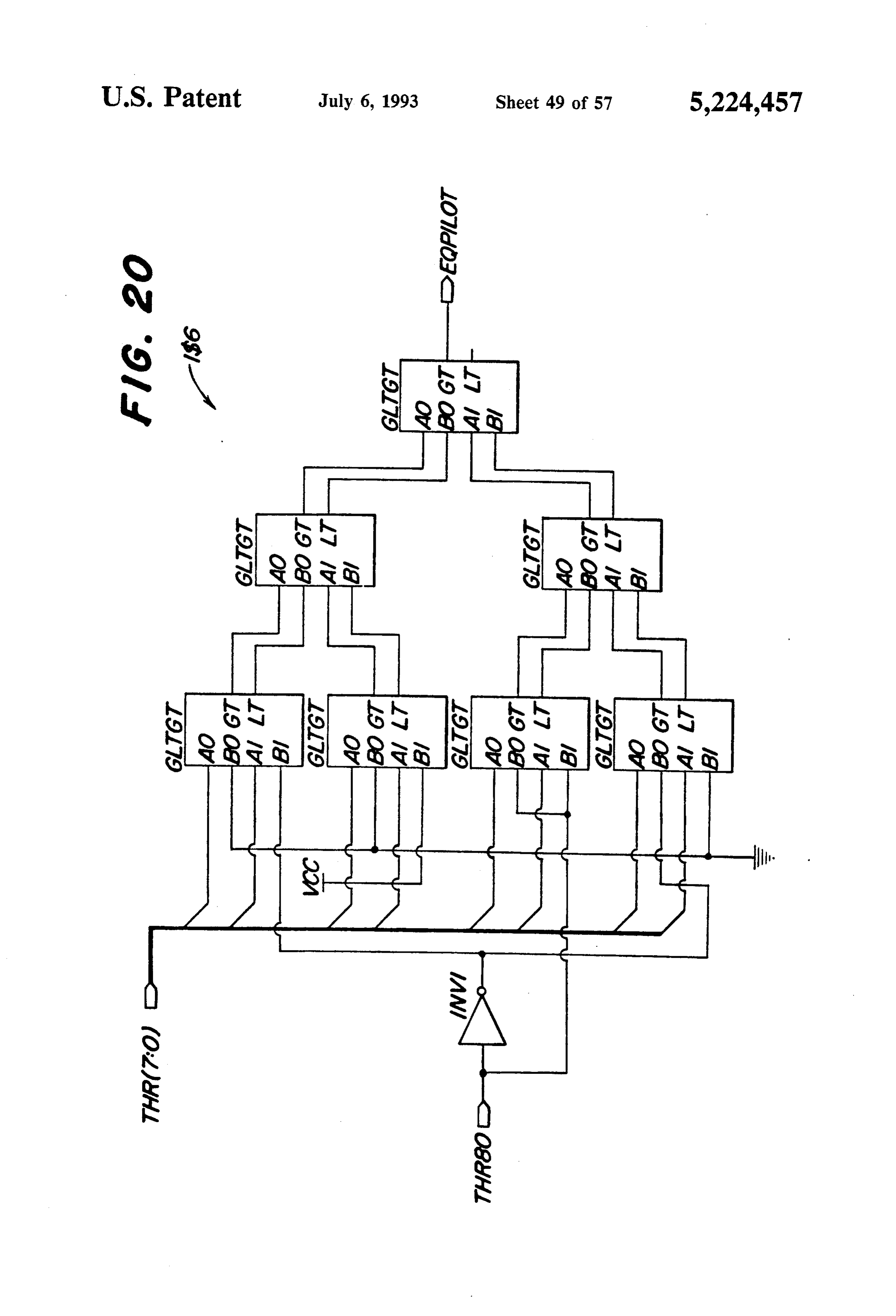
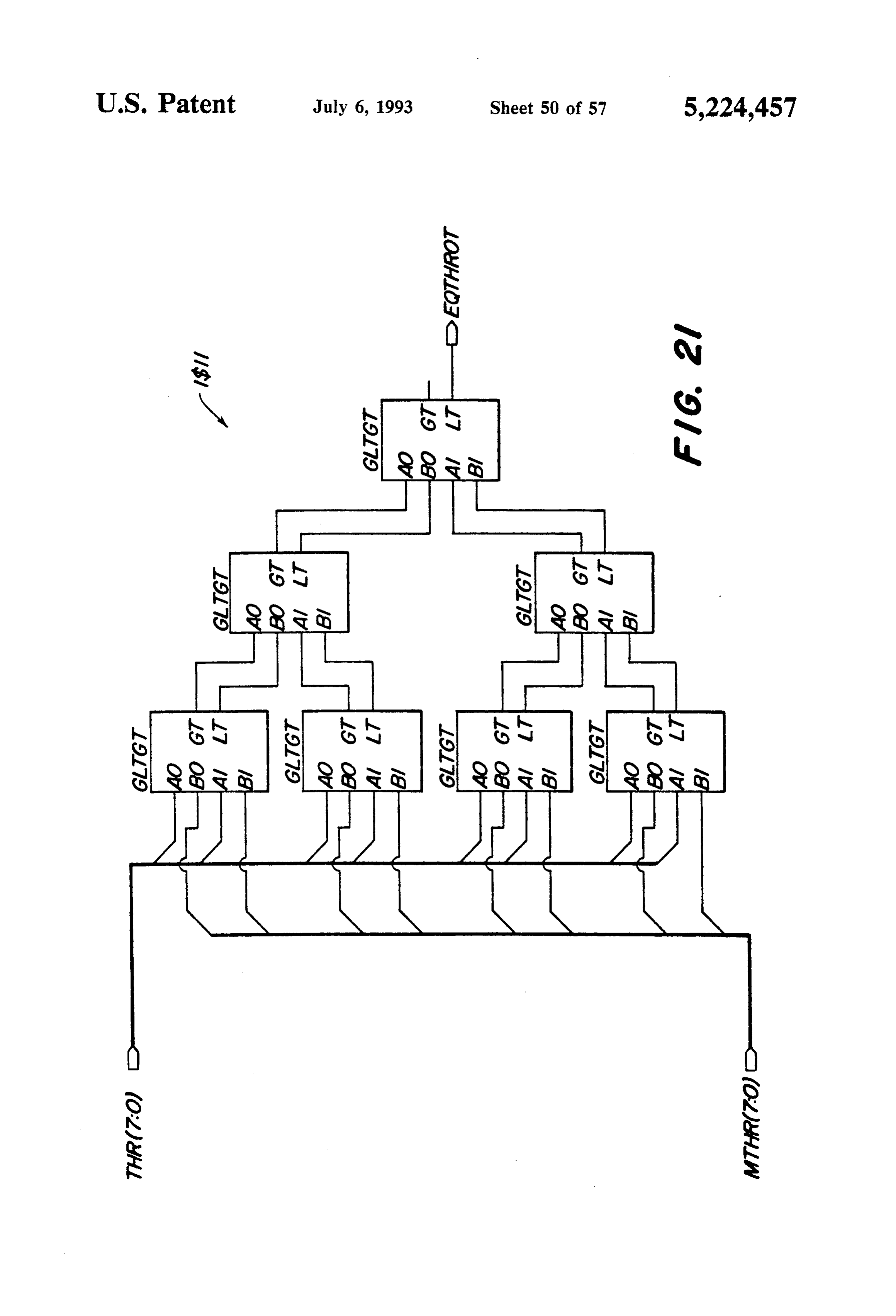
FIG. 15 is a detailed schematic diagram illustrating valve 30. The natural gas regulator 28 works in con the Programmable Gate Array design of the engine junction with a balance tube 29, and thus maintains the load comparator circuit (element IS2281) of FIG. 9d. pressure of the NG supplied to the metering valve 30 FIG, 16 is a detailed schematic diagram illustrating higher than the air pressure at the entrance of the mixer the Programmable Gate Array design of the speed ad 5 32 by a pressure differential in the range of 7 to 11 just detection circuit (element IS1301) of FIGS.9b and inches of water, depending on the engine application. 9f This compensates for the fact that, as engine power is FIG. 17 is a detailed schematic diagram illustrating increased, more air is being pulled through the air the Programmable Gate Array design of the lamp cleaner 22 and more vacuum is drawn in the air mixer driver circuit (element IS5) of FIGS. 9c and 9i O 32. In this way, the supply of NG to the air mixer 32 is FIG. 18 is a detailed schematic diagram illustrating automatically compensated for a dirty air cleaner or for the Programmable Gate Array design of the throttle the absence of an air cleaner, and for changes in engine setpoint circuit (element IS9) of FIGS. 9c and 9i loading.
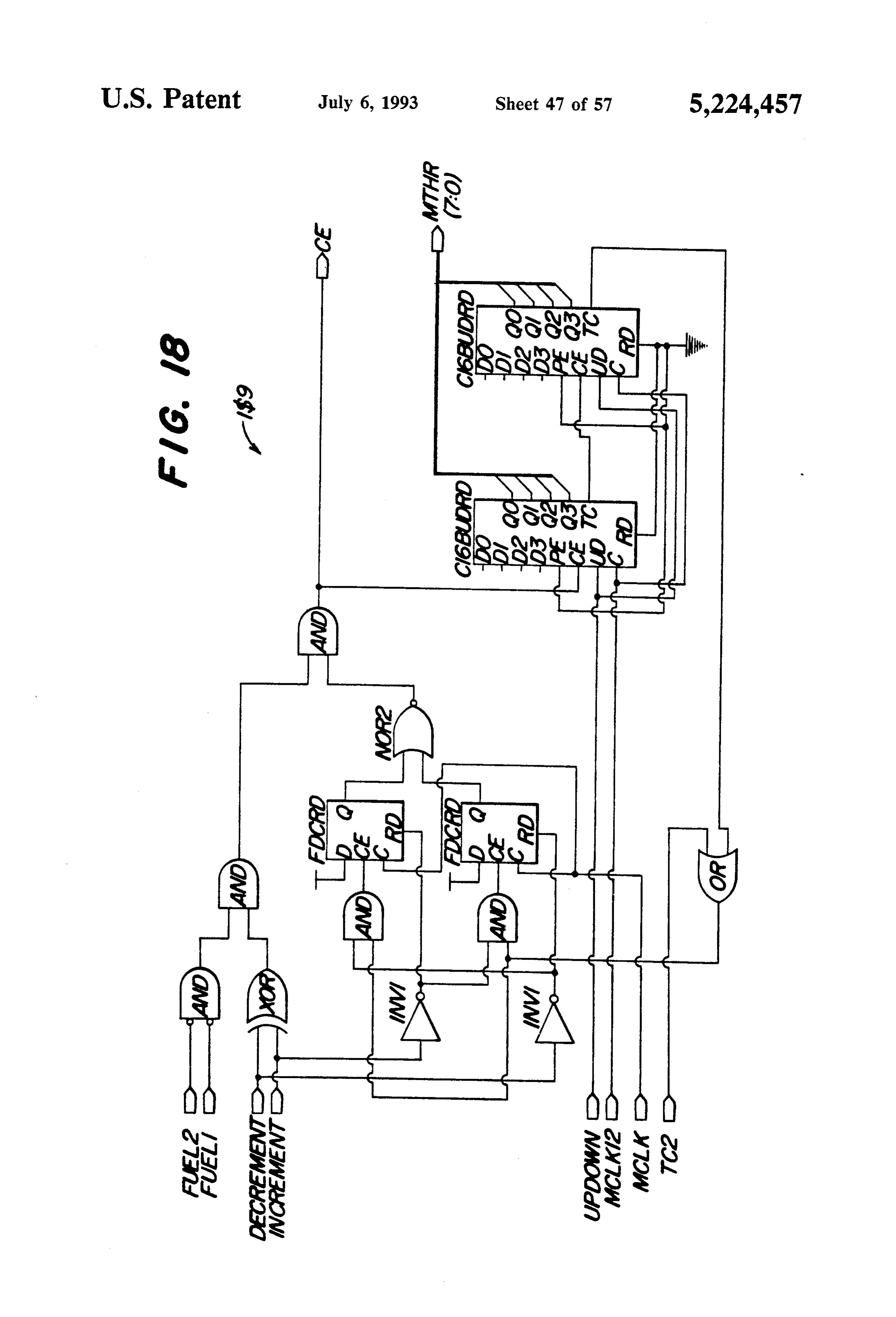
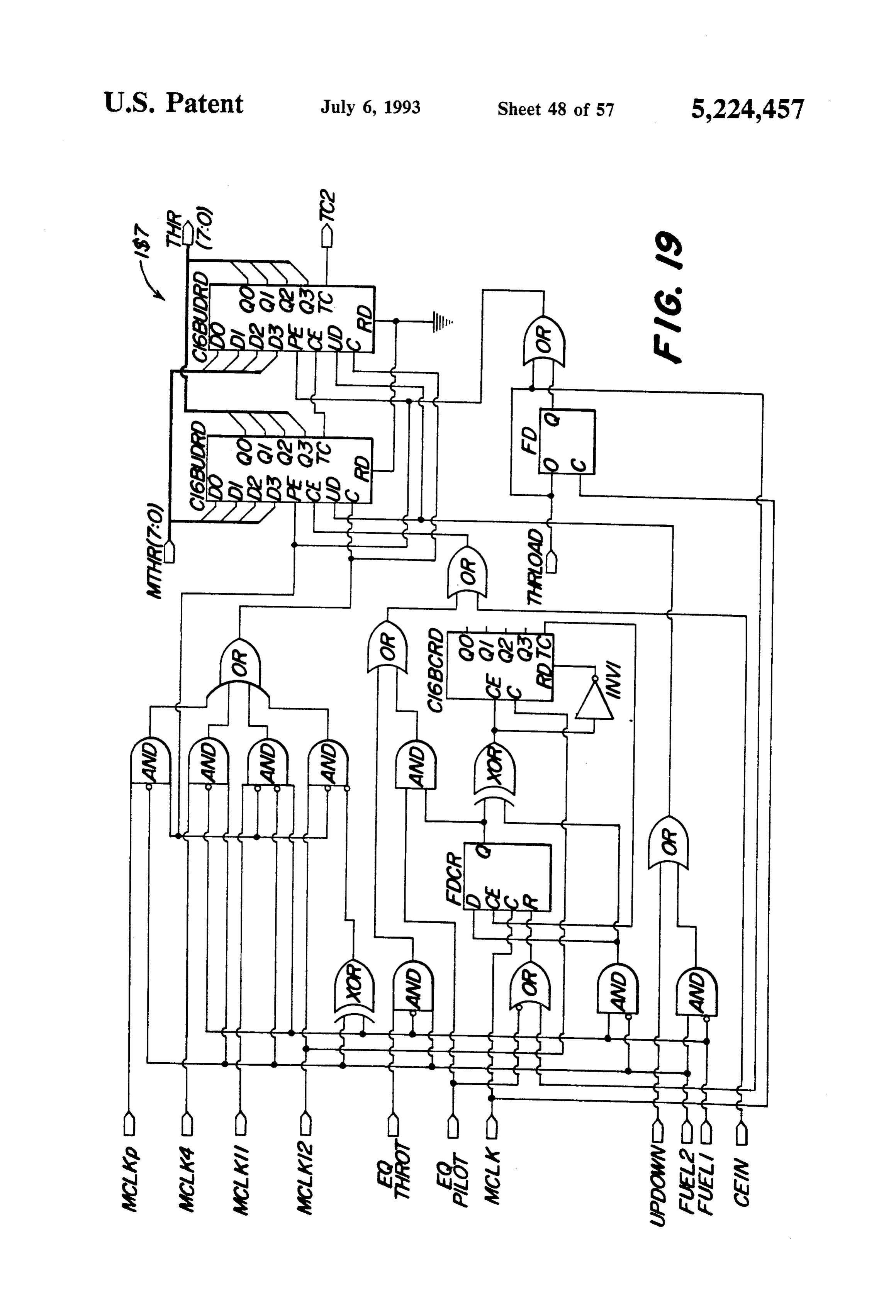
FIG. 19 is a detailed schematic diagram illustrating The mixer 32 is essentially a cylindrical tube with an the Programmable Gate Array design of the throttle 5 aperture (not shown) for connecting to the balance tube ramp control circuit (element IS7) of FIGS. 9e and 9m. 29 and with an aperture (not shown) for receiving NG FIG. 20 is a detailed schematic diagram illustrating the Programmable Gate Array design of the pilot throt from A the metering valve 30.
diesel electronic control unit 34, ECU, controls the tle comparator circuit (element IS6) of FIG. 9e. diesel fuel injection pump 14. Preferably, the ECU 34 is FIG. 21 is a detailed schematic diagram illustrating a commercially available
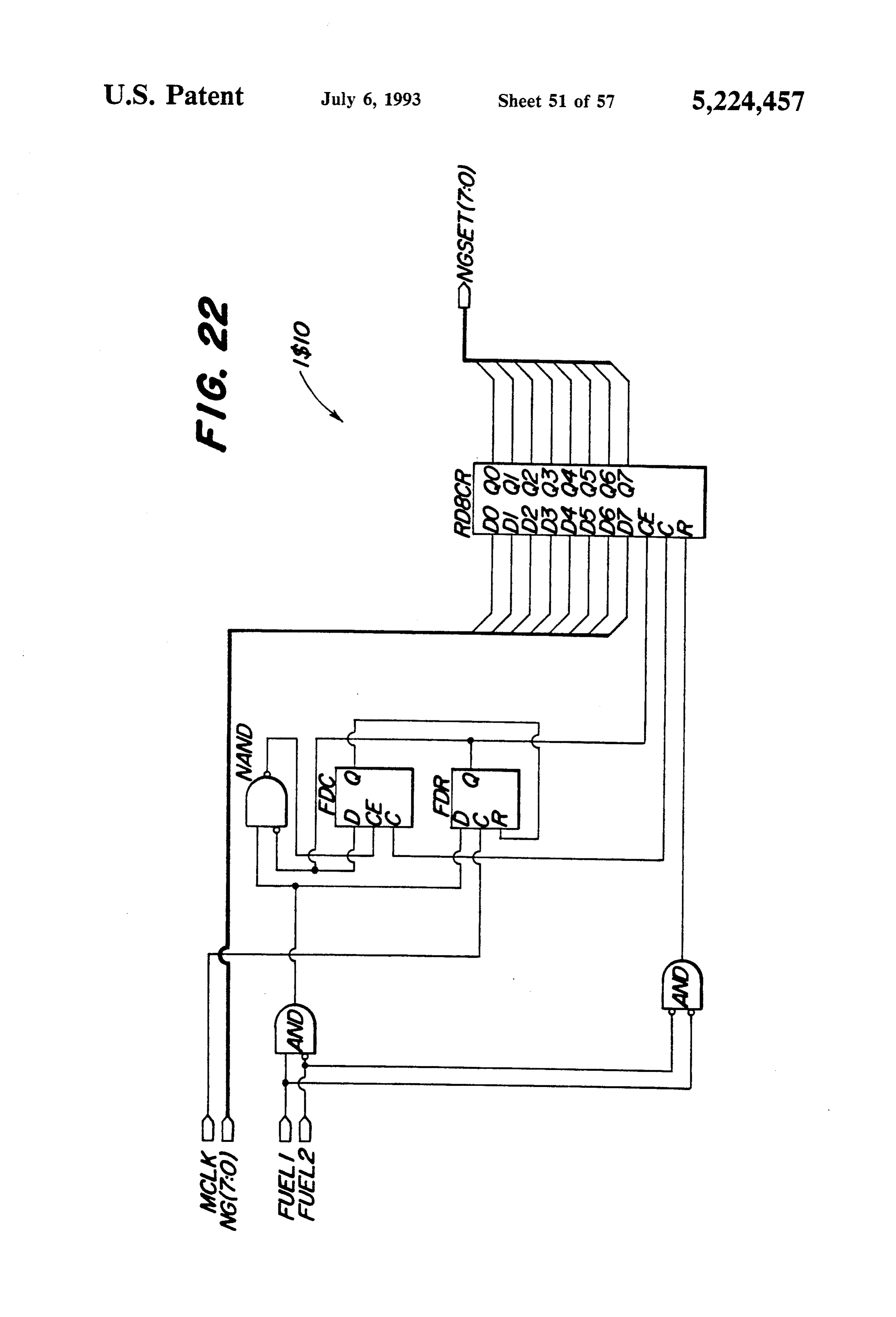
the Programmable Gate Array design of the throttle by Nippondenso. The ECUECU, 34 is such as manufactured preferably configured comparator circuit (element IS11) of FIGS. 9c and 9k. as a MIN/MAX governor for dual fuel operation, and FIG. 22 is a detailed schematic diagram illustrating receives an engine speed signal from a conventional the Programmable Gate Array design of the NG speed engine speed pick-up 35 such as a magnetic pick-up. In setpoint circuit (element IS10) of FIGS. 9e and 9m. 25
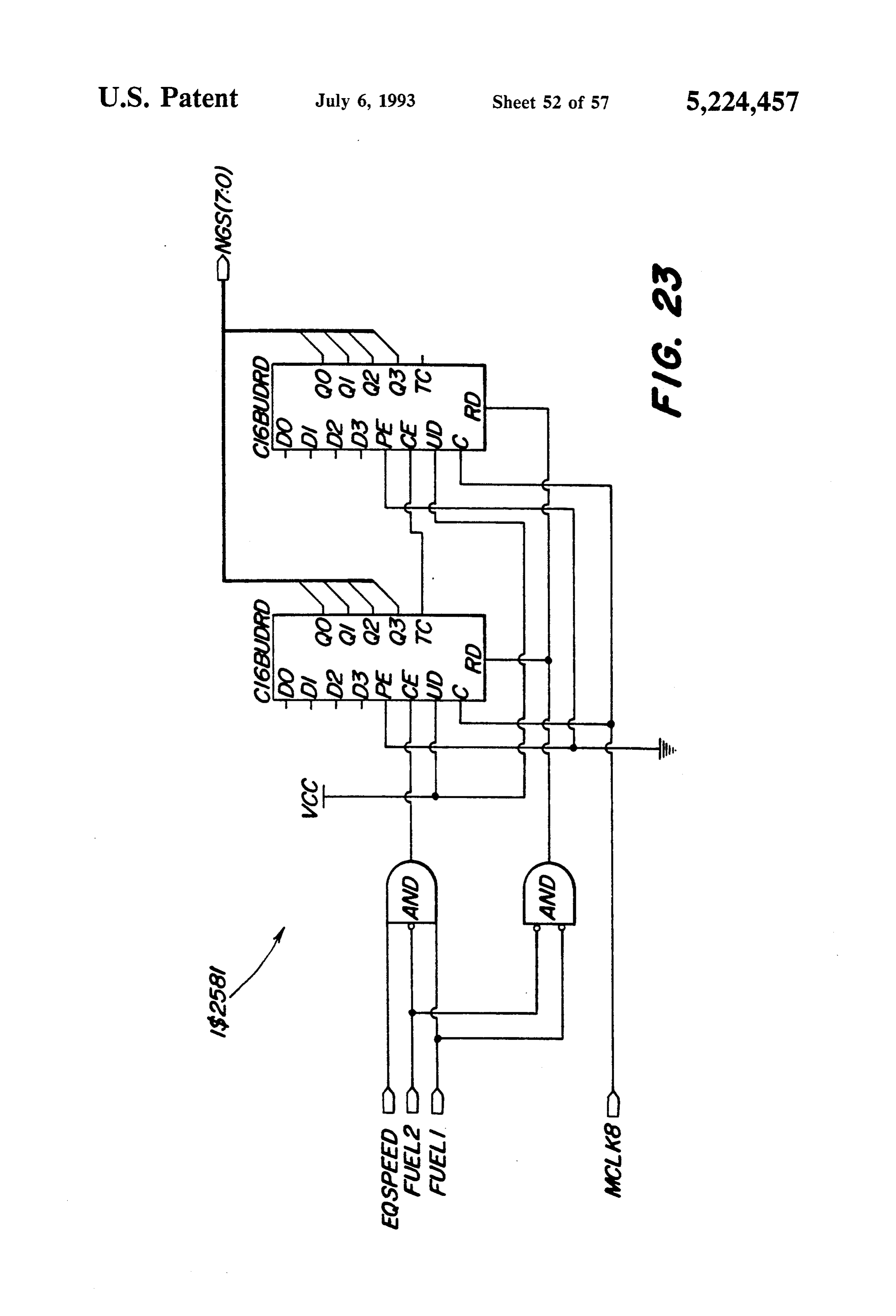
FIG. 23 is a detailed schematic diagram illustrating MIN/MAX mode, diesel fuel delivery is primarily a the Programmable Gate Array design of the Speedramp function of the setting of a throttle (not shown), how circuit (element IS2581) of FIGS. 9e and 9o, ever, idle speed and maximum speed are still governed FIG. 24 is a detailed schematic diagram illustrating by the ECU 34. In addition, the required diesel pilot the Programmable Gate Array design of the NGspeed 30 quantities for dual fuel operation are "end pro comp circuit (element IS2582) of FIGS. 9e and 9p. grammed" into the ECU memory as de-rated torque FIG. 25 is a graphical illustration of the ECU torque curves, as best seen in FIG. 25, wherein curve B is the limiting curves which are "end programmed' into the torque curve for pure diesel fuel operation, curve A is ECU memory, the dual fuel boost pilot torque curve for greater than 80% load and curve C is the dual fuel pilot torque curve
FIG. 26 is a graphical illustration of the speed set 35 for point requirements for the governor of the present in less than 80% load.
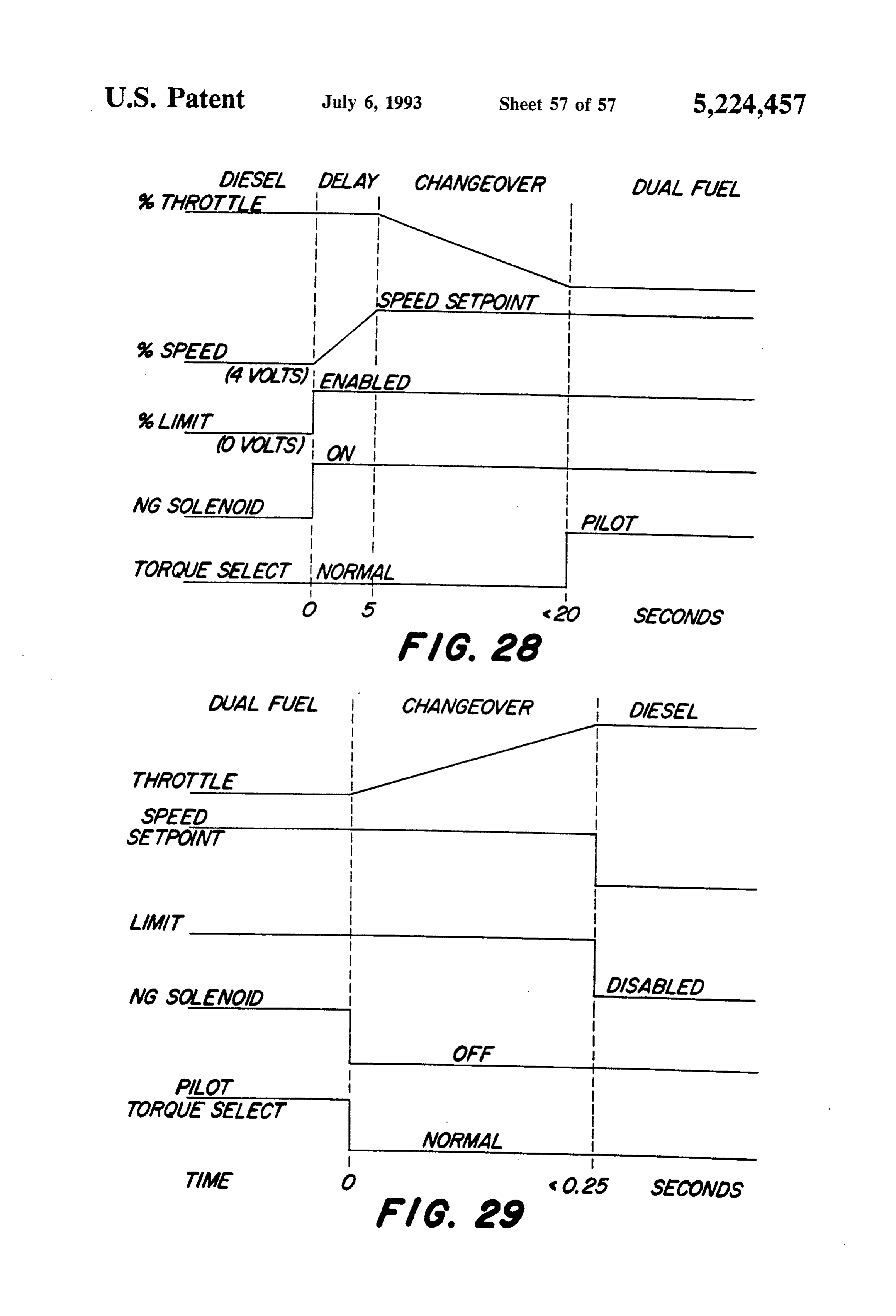
vention. A governor or NG controller 36 controls a rotary FIG. 27 is a graphical illustration of the NG fuel actuator 38, which in turn controls the metering valve limiting curves for the dual fuel engine of the present 30. The metering valve 30 is preferably a commercially invention. 40 available metering valve, such as part number 252-688 FIG. 28 illustrates the changeover sequence from manufactured by Century, and the rotary actuator 38 is diesel fuel to dual fuel operation. preferably a commercially available rotary actuator, FIG. 29 illustrates the changeover sequence from such as a "DYNA 7000" manufactured by Barber-Col dual fuel to diesel fuel operation. man. The governor 36 receives an engine speed signal 45 from a conventional engine speed pick-up 37 such as a
DETALED DESCRIPTION magnetic pick-up.
Referring to FIG. 1, the dual fuel engine system 10 The governor 36 is preferably a commercially avail includes a conventional diesel engine 12 which is sup able governor, such as model DYN1 10524, manufac plied with diesel fuel from a standard diesel fuel injec tured by Barber-Colman. The governor 36 includes an tion pump 14. Also included is a conventional intake SO internal speed adjust potentiometer (not shown) which manifold 16. An optional intercooler pump 18 and Sets the low governing speed for dual fuel operation and charge air temperature switch 20 may be included in the the governor 36 provides the required speed governing case of an engine over a certain horsepower, such as 200 range of 1200 to 2300 RpM which is controlled by a hp. Air is supplied to the engine 12 by a conventional air voltage from the link controller 40. Preferably, the cleaner 22 and turbocharger 24. The turbocharger 24 55 governor 36 will have a speed setpoint versus RPM preferably includes an o-ring seal (not shown) in the characteristic within the limits shown in FIG. 26. compressor housing to prevent leakage to atmosphere The link controller 40 manages the operation of the of the air/gas mixture which flows through the com diesel ECU 34 and NG controller 36, and provides pressor. operator controls via an operator's panel 42. In addi Natural gas NG is supplied to the engine 12 from a tion, the link controller 40 will automatically switch NG source 25 (preferable 20 psi) via a solenoid between diesel and dual fuel operation as conditions operated NG shutoff valve 26, a NG regulator 28, a permit and as commanded by the operator. The gover metering or NG valve 30 and a NG/air mixer 32. Thus, nor 36 is a speed control governor which tries to main the natural gas is introduced at the natural gas/air mixer tain a constant engine speed. It receives signals from the 32 between the inlet to the compressor of the turbo 65 link controller 40 which represent a desired engine charger 24 and the air cleaner 22. speed, for example, 1800 rpm. The governor 36 func The natural gas regulator 28 reduces the incoming tions to maintain this 1800 rpm engine speed by opening pressure down to a useable pressure for the metering and closing metering valve 38.
Page 61
A transient voltage protection device TVP 45 is a FIG. 3 illustrates the interconnections between the known current production circuit breaker type module link controller 40, the ECU 34, the operator's panel 42, that protects the ECU 34, link controller 40 and the the governor 36 and the solenoid-operated NG shut-off governor 36 against voltage spikes and reverse battery valve 26. Thus, the link controller 40 is not a 'stand connection. 5 alone' electronic controller. It functions as an interface A low pressure switch 46 detects whether the pres between the operator and the ECU 34 (used for govern sure supplied by the natural gas supply 25 is sufficient to ing the engine 12 in diesel operation) and the governor fully power the engine 12. Switch 46 is preferably a 36 (used for speed control in dual fuel operation). Thus, normally-closed pressure sensitive switch which opens the electronics for the complete dual fuel control sys at pressures above approximately 18 psi. Once open, O tem consists of an operator's panel 42, the link control internal hysteresis prevents the switch 46 from closing ler 40, the ECU 34 and the governor 36. until the pressure is below approximately 13 psi. If the Link Controller low NG pressure switch 46 closes, the link controller 40 will force a return to pure diesel operation or prohibit a FIG. 4 shows the overall link controller 40 system. changeover to dual fuel operation. 15 The design is partitioned into input and output condi The charge air temperature switch 20 senses air tem tioning circuitry 62, 64 and control circuitry 66, and is perature in the intake manifold, and, is preferably a integrated into the dual fuel system via a connector (J1), normally-open temperature sensitive switch, which such as a 30-pin Packard-type connector.
closes at temperatures above 53° C. (128 F.). Once Referring now to FIGS. 5, the input conditioning closed, internal hysteresis prevents the switch 20 from, 20 circuitry 62 for the link controller 40 provides low pass reopening until the temperature is below 48 C. (118 filtering of all incoming signals, protects against exter F.). If the intake air temperature is too high the switch nally generated voltage or current spikes such as ESD 20 closes and the link controller 40 will force a return to (electro static discharge), and conditions signals from pure diesel fuel operation or prohibit a changeover to mechanical switch contacts and external sensors in dual fuel operation. This can help avoid knocking in 25 order to help reduce noise and switch contact bounce. higher horsepower engines, and protect the engine 12 if The four switch inputs (User Diesel/User Dual Fuel, an external hose or if the belt that drives the intercooler Increment/Decrement, LowNG, Intake Air) to the link pump 18 would break. controller 40 have similar input protection circuitry, Appropriate connections may also be made to an with the exception of the intake air temperature sensor engine monitoring panel 44 which could include con 30 switch 20 and the low NG pressure switch 16. For these ventional engine gauges such as a tachometer, a fuel inputs positive temperature coefficient thermistors gauge, a temperature gauge, an oil pressure gauge and (RT1 and RT2) are used to provide "contact wetting etC, to these sensor switches. This means that when the Referring now to FIG. 2, the operator's panel 42 Sensor switch closes, current will flow through the includes a fuel select switch 50 which is a single pole, 35 thermistor and across the contact to help keep the double throw, momentary contact switch which selects contact clean. As the thermistor heats up, this current diesel or dual fuel operation. A speed control switch 52 flow is reduced to a trickle current. The other two is a single pole, double throw, momentary contact inputs are provided by sealed, "dry" gold contact switch which provides a speed increment or speed dec Switches and so no "contact wetting is required. rement signal to the link controller 40. The link control 40 The resistors R7-R11, R13 and capacitors C1, C2, ler 40 in turn generates a diesel throttle signal (%. Throt C5-C8, C11 provide a low-pass RC filter to ground tle) which is supplied to the ECU 34. The diesel throttle with a 3dB cut-off frequency of 1.45 kHz. The resistors signal is in effect a fuel setting. Engine speed is deter R1-R6 are internal pull ups to Vcc for the case when a mined by the engine load. switch is open.
The operator's panel 42 also includes the following 45 The Schottky diode clamps (D9-D16) protect the indicator lamps. A diesel fault lamp 54 is controlled by MC14490 switch debouncer (U2A-U2D) against posi the ECU 34 and is lit to indicate the presence of an ECU tive or negative voltages, limiting the input voltages 34 fault. A diesel lamp 56 which is controlled by the link from (GND -0.4V) to (Vcc +0.4 V). The signal diode controller 40 and is lit to indicate that the engine 12 is SO clamps (D1-D8) protect the MC74HC14 Schmitt trig running on pure diesel fuel. A dual fuel lamp 58 is con ger (U1A-U1F) against positive or negative voltages, limiting the input voltages from (GND -0.7 V) to (Vcc trolled by the link controller 40 and is lit to indicate that the engine 12 is running in its dual fuel mode. The ECU +0.7 V).
34, the NG governor 36 and the link controller 40 are The MC14490 is a switch debouncing circuit, used preferably mounted in a housing (not shown) to which for the elimination of extraneous level changes that the panel 42 is mounted. 55 result from the opening and closing of user-controlled The following Table describes the operation of lamps mechanical switches. The MC14490 takes an input sig 56 and 58: nal from the operator switches and generates a clean digital signal four clock periods after the input has stabi
Diesel Dual Fuel lized. This applies to opening and closing the contact.
Lamp Lamp Operation Mode The capacitor C3 sets the internal R-C oscillator at 87 ON OFF Diesel node/switch over to diesel
Hz which requires that the switch contact settle out in
ON FLASH User select dual fuel/switchover to 20 msec before a transition is detected.
dual fuel disabled/speed adjustment The MC74HC14 Schmitt trigger circuit serves the while running dual fuel same purpose as the MC14490 for the engine sensor 65 switches, enhancing noise immunity by reducing wave
OFF ON Dual fuel mode/switchover to dual fuel form transition times.
FLASH ON Switchover to diesel fault
The NG valve position input is an analog 0-5 signal from a feedback position sensor (not shown) on the NG
Page 62
rotary actuator 38. This signal provides an indication of Regulators (U3, U10, U11) are low dropout voltage the engine load while operating on dual fuel. The input regulators for 5 and 10 V supplies. They can source 1 is filtered by the low-pass RC network to governor 36 amp of output current with a dropout voltage of 0.5 V GND with a 3dB cut-off frequency of 159 Hz with the to 1 V over the 40 C. to 125° C. operating range. The diodes providing overvoltage protection by limiting the 5 1 uF and 110 uF capacitors, C12, C25 for example, input voltage between -0.7 V and 5.7 V. included with each such regulator, are required to main The AUXRPM input is a 0-5 V TTL signal from the tain stability and regulation during transients and are ECU 34 which is generated by the speed sensor 35 on physically located close to the regulators. the engine 12. The ECU 34 outputs 10 pulses per engine The oscillator circuit consists of a 12.8 kHz tuning revolution, and the link controller 40 uses this signal to O fork series oscillator (Y1), three resistors (R31, R32, calculate engine RPM. Engine speeds in the range of R33) and the MC14060 (U12) oscillator/divider. This 1200 to 2400 RPM generate RPM input frequencies of provides a free-running clock frequency of 12.8 kHz, 200 to 400 Hz. This input is low-pass filtered by the RC and also provides several divided-down clock frequen network to ECU 34 GND (396 Hz 3 dB cut-off). The 15 cies, all for use within the PGA for timing applications pull-down resistor (R67) pulls the input low in the case (Q4: 800 Hz, Q6:200 Hz, Q8: 50 Hz, Q10: 12.5 Hz, Q14: where there is no RPM input connected. 0.78 Hz).
Referring now to FIG. 6, there is shown the link The 12.8 kHz base frequency was chosen as the most controller control circuitry 66 which manages the dual appropriate for RPM calculation, based on the incom fuel operation of the engine 12. The link controller 66 is 20 ing RPM signal from the ECU 34, and is sufficient for primarily a digital controller, with some analog input allThe other control functions. and output circuitry. The link controller control cir feedbackLM2903 comparator U13 compares the position signal from the rotary actuator 38 with a 4.3 V cuitry 66 includes a Programmable Gate Array (PGA) reference. This provides an indication of whether the (described in detail later), such as is commercially avail able from Xilinx, Inc. The Xilinx PGA is a standard 25 engine is running under or over 30% load on dual fuel. R34 and R35 provide 50 mV of hysteresis to the com off-the-shelf component available in military and auto parator circuit and the 10K pullup resister R28 to Vcc motive temperature ranges. The PGA is electronically ensures that the comparator output is compatible to configured at power-up, by data downloaded from an PGA logic levels.
8-pin serial PROM (Programmable Read-Only Mem The 27C64 EPROMs (U4, U5 of FIG. 6) provide 2 ory) U9. The PGA is configured through the use of lookup tables as a function of engine RPM: development tools, which are also commercially avail 1. NG 7% Speed Setpoint for governor 36. able from Xilinx, Inc., to implement the circuits and 2. NG 9% Limit for NG Valve Position limiting on functions which will be described in detail later. dual fuel.
The link controller 40 provides regulated power supplies and separate grounds for the digital portions of 35 table is purpose
The
of the NG % Speed setpoint lookup provide a speed setpoint voltage to the gover its control circuitry 66, for the ECU 34 interface cir nor 36, based on the engine RPM measured at the time cuitry and governor 36 interface circuitry. The power of switchover from diesel to dual fuel. The ECU 34 supply for the dual fuel system consists of a 12V battery requires a 0.5-4.5 VDC throttle voltage to determine (not shown) and alternator (not shown), and the Tran fueling, whereas the governor 36 requires a 4-8 VDC sient Voltage Protection (TVP) module 45. A 12 V speed setpoint voltage. This fundamental difference supply for the link controller 40 is provided from an between the controllers requires that the link controller output of the TVP module, which protects the ECU 34, 40 calculate and provide the appropriate signals, to governor 36 and control circuitry 66 from reverse volt ensure smooth transitions between diesel and dual fuel age connection and large inductive load dumps from modes.
the alternator. 45 The purpose of the NG 26 Limit lookup table is to For the control circuitry 66 digital circuitry, +12 V prevent over-fueling of the engine by the governor 36. is brought in on pin BATT150, with GND brought in The governor 36 is a speed governor so it will supply directly from battery negative. For the ECU 34 inter whatever NG is required to attain the speed setpoint. It face circuitry, +12 V is brought in on the ECU 12 V has been determined from engine mapping work that pin with GND connected to the ECU signal GND. For 50 engine over-fueling at certain speeds will cause the the governor 36 interface circuitry + 12 V is brought in engine to knock. The NG% Limit places limits on the on a 12V pin with GND connected to the governor 36 position of NG valve 30 as a function of RPM, in order power GND. In addition, the link controller 40 control to prevent engine knocking. The NG% Limit Lookup circuitry 66 takes in regulated 4 V and 8 V supplies from table actually contains two maps of NG valve 30 posi the governor 36 and regulated 5 V supply from the 55 tion as a function of RPM:
ECU 34. These are used strictly for the purpose of 1. position limit with normal diesel pilot. providing voltage references for analog inputs and out 2. position limit with boost diesel pilot. puts. The PGA controls the selection of normal or boost The ferrite beads (L1-L8) are used on power and diesel pilot.
GND inputs to enhance noise immunity of control cir The three DAC0830 digital-to-analog converters, cuitry 66. At low frequencies, the ferrite beads look like (U6, U7, U8) are required to convert internal digital a short circuit, but at higher frequencies, they act like a values to external analog control voltages:
50 ohm resistor. Thus, each ferrite bead in combination 1. NGLimit: 0-8 VDC required by governor 36. with one of capacitors C12, C19, C21, C33, C34 and 2. NGSpeed: 4-8 VDC required by governor 36. C35, provides a low-pass filter with a 3dB cutoff fre 65 3. DThrottle: 0.5-4.5 VDC required by ECU 34. quency of 3.18 KHz. This input protection increases the The digital-to-analog converters (DAC) U6-U8 are link controller's immunity to electromagnetic interfer configured for single power supply operation with level ence (EMI). shift and span-adjustable outputs. The LM124 op amps
Page 63
U15, U16 take their inputs from the appropriate resis cuits are embodied within the configured PGA, and tor/divider networks to provide the various reference thus, a description of the structure and function of these and offset voltages for the 3 ranges required. The output circuits will constitute a description of the structure and LM124 stages for NGLimit and NGSpeed have again function of the PGA.
of 2, so the reference voltages provided at the DAC The Link Controller design uses the XC3042PC84I inputs are those required at the output. This is due to 50 version of the PGA. This is an 84-pin surface mount the fact that the DAC will only output 0-5 VDC in this device with 74 user-available inputs and outputs, and configuration. As this is not a microprocessor applica 144 Configurable Logic Blocks “CLB". tion, the two Write lines, Chip Select and Transfer pins The PGA performs the following functions: are not used and are tied to GND, and the RFB and O 1. Calculates an engine RPM value from the ECU 34 ILE pins are tied to 10 V. supplied RPM signal.
The pulldown resistors (R17, R68-R82) are used to 2. Allows start-up in pure diesel fuel mode and allows pull down the DAC inputs for NGLimit and DThrottle. normal diesel operation if desired. In the case of NGLimit, the lookup table output is en 3. Controls fuel selection and changeover from diesel abled low by the PGA during diesel operation in order 15 to dual fuel and vise versa. to force 100% 7% Limit on the governor 36 (no NG). In 4. Controls operator speed adjustments and provide . the case of DThrottle, the % Throttle signal to the appropriate signals to the ECU 34 and governor ECU 34 is ensured to be low (0.5 V) at power up. 36. This includes selection of the ECU 34 Torque Link Controller Output Conditioning Circuitry 20 limiting function (Torque Select). 5. Compares NG Valve 30 position with a fixed refer
Referring now to FIG. 7, the output conditioning ence value representing approximately the position circuitry 64 protects the internal control circuitry 66 at 30% load.
from voltage and current spikes which may occur exter 6. Compares diesel throttle with fixed reference val nally. The circuitry 64 also conditions outgoing signals ues representing approximately 40% load and 80% to provide appropriate impedance matching and cur load values.
rent capabilities. 7. Monitors diagnostics (Intake Air Temperature, The three analog output signals are %. Throttle Low NG Pressure, Engine RPM and Engine (0.5-4.5 VDC) to the ECU 34% Speed (4–8 VDC) and Load) which would affect the engine mode of % Limit (0.6-8 VDC) to the governor 36. Each of the operation and forces a fuel changeover to diesel, if analog output voltages has a Zener diode which limits necessary.
the voltage at the outputs to 5.1 V (% Throttle) and 8.7 8. Controls illumination of the Diesel lamp 56 and V. Each resistor R52, R54 provides internal current Dual Fuel lamp 58.
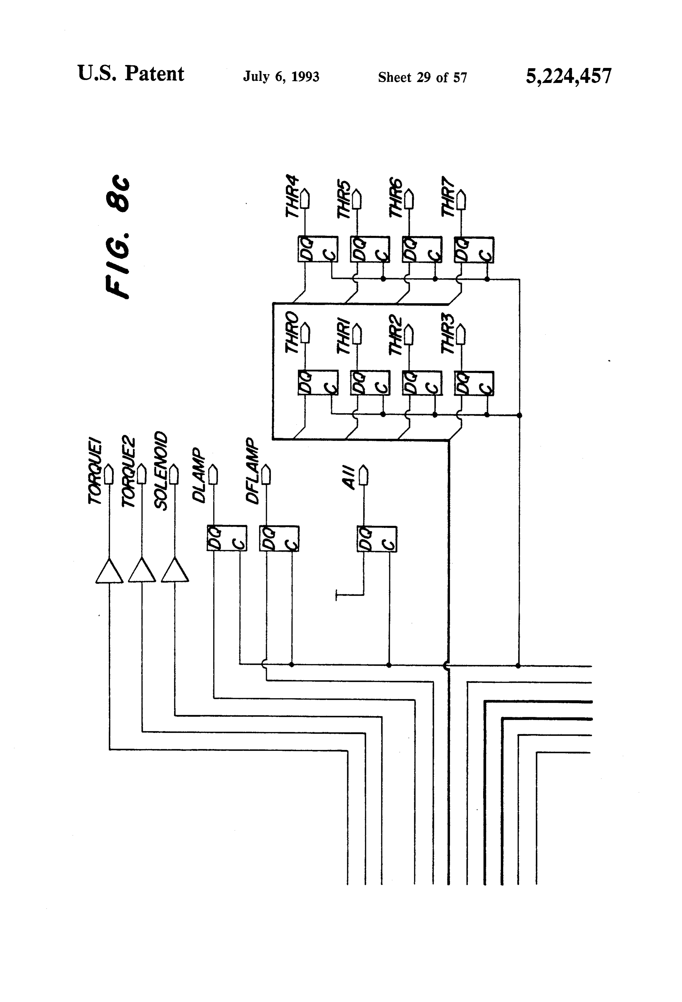
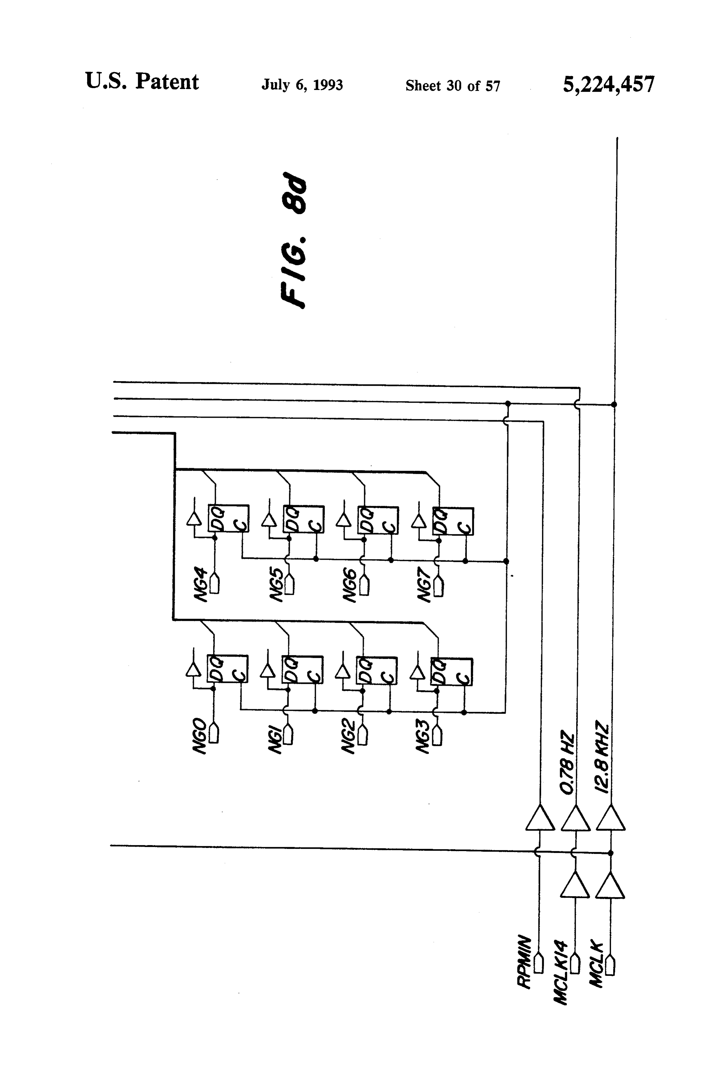
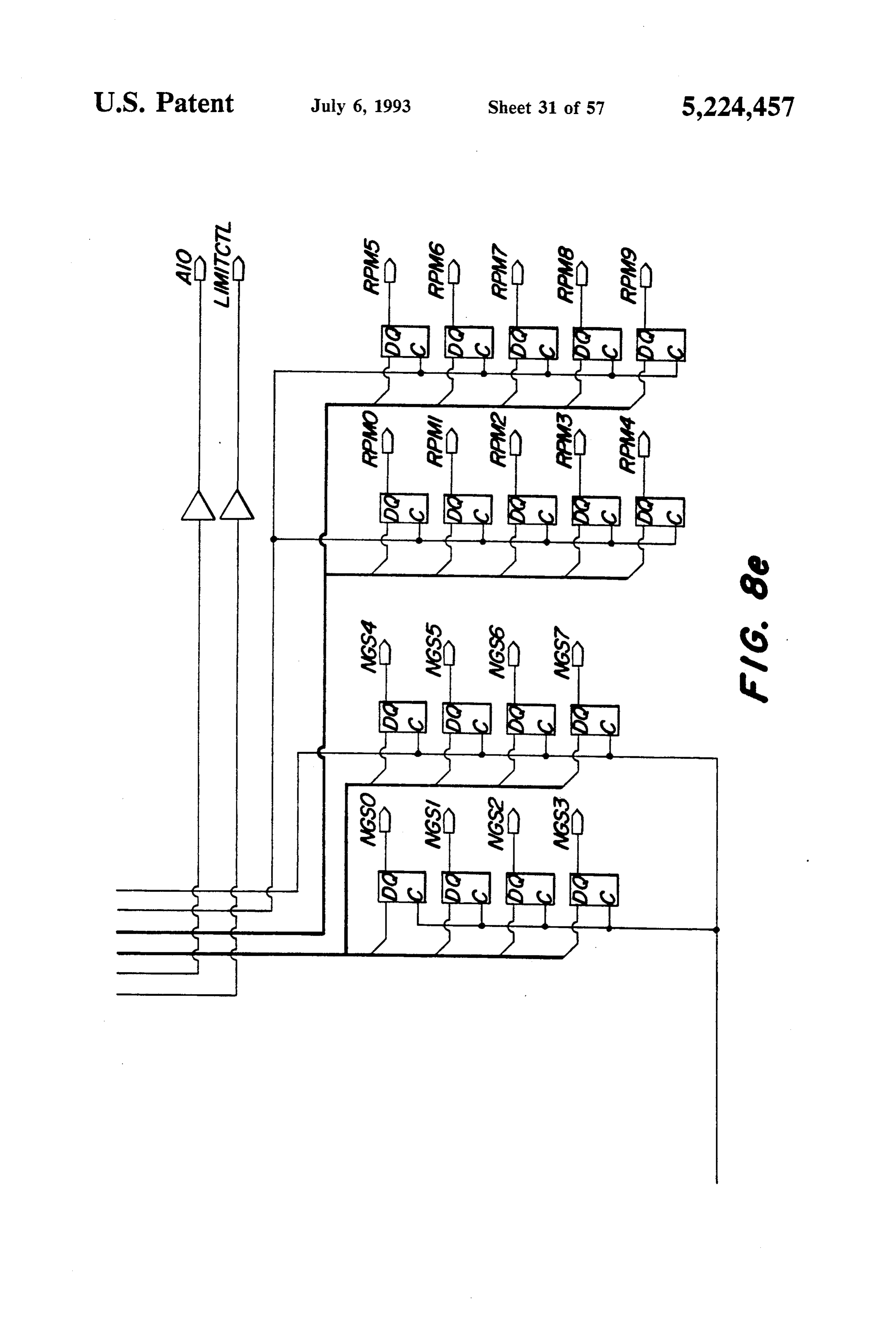
limiting while the resistors R46, R47 for %. Throttle and The control circuitry implemented by the PGA will % Speed pull the outputs to GND at power-up. now be described in a hierarchical manner. Referring The PGACONFIG output is a digital test signal used 35 now to FIG. 8, there is shown a top level schematic of to indicate if the PGA configuration at power up was the functional blocks in the PGA.
successfully completed. The output protection circuitry The Link Controller (ISO) functional block represents used is similar to that used for the three analog signals. all digital logic which is configured using the Xilinx The diesel lamp 56 and dual fuel lamp 58 run off the PGA CLBs (not shown). The circuitry shown external 12 V supply (12 V, 500 mA typical) and are turned on to this block is configured using the Xilinx PGA Input or off by the link controller 40. The resistors R50, R51 /Output Blocks (IOBs) (not shown). The inputs and provide pulldown at power-up and internal current outputs are buffered or latched and can be configured limiting. The logic-level FETs Q3, Q4, when turned on for CMOS or TTL logic.
(logic 1 at input), will sink the required current from the The following inputs are buffered: lamps. 45 1. A UserDualFuel input allows the user to select The Torque Select driver circuit is similar to the dual fuel operation from a momentary contact switch. Diesel and Dual Fuel Lamp drivers with Q1 and Q5 A UserDualFuel = 1 represents no selection, while a wired together in a wired-OR configuration. With R59 UserDualFuel =0 represents dual fuel selection. in series with Q5, the Torque Select output can be con 2. A UserDiesel input allows the user to select diesel trolled to one of 3 states. These states are selected by the 50 operation from a momentary contact switch. A User link controller 40 PGA. Diesel = 1 represents no selection, while a User The NG solenoid output driver circuit is also very Diesel =0 represents diesel fuel selection. similar to the above three discussed, with the 2 watt 3. An increment input allows the user to increase Zener diode (D21) added to provide protection against engine speed via actuation of a momentary contact inductive kickback from the solenoid of NG valve 26. 55 switch. An Increment = 1 represents no selection, while Programmable Gate Array an Increment=0 represents an increase in engine speed. 4. A Decrement input allows the user to decrease
The majority of the link controller 40 logic and con engine speed via actuation of a momentary contact trol functions are designed into the PGA. Similar to a switch. A Decrement=1 represents no selection, while microprocessor, the PGA is a program-driven logic a Decrement c0 represents a decrease in engine speed. device. As stated earlier, an external serial PROM (Pro 5. An Intake Air sensor switch input indicates when grammable Read-Only Memory) downloads a desired the intake air temperature to the engine exceeds 53 internal configuration into the PGA at power-up. A degrees C. An IntakeAir =l represents no fault configuration program is loaded automatically from the (T<53), while an IntakeAir=0 represents a fault PROM upon power-up or following an external reset. 65 (Td 53).
The configuration program is derived from the circuit 6. A LowNG sensor switch input indicates when diagrams shown in FIGS. 8-22 using the commercially available NG Pressure for dual fuel operation is less available Xilinx design tools and software. These cir than 13 psi.
Page 64
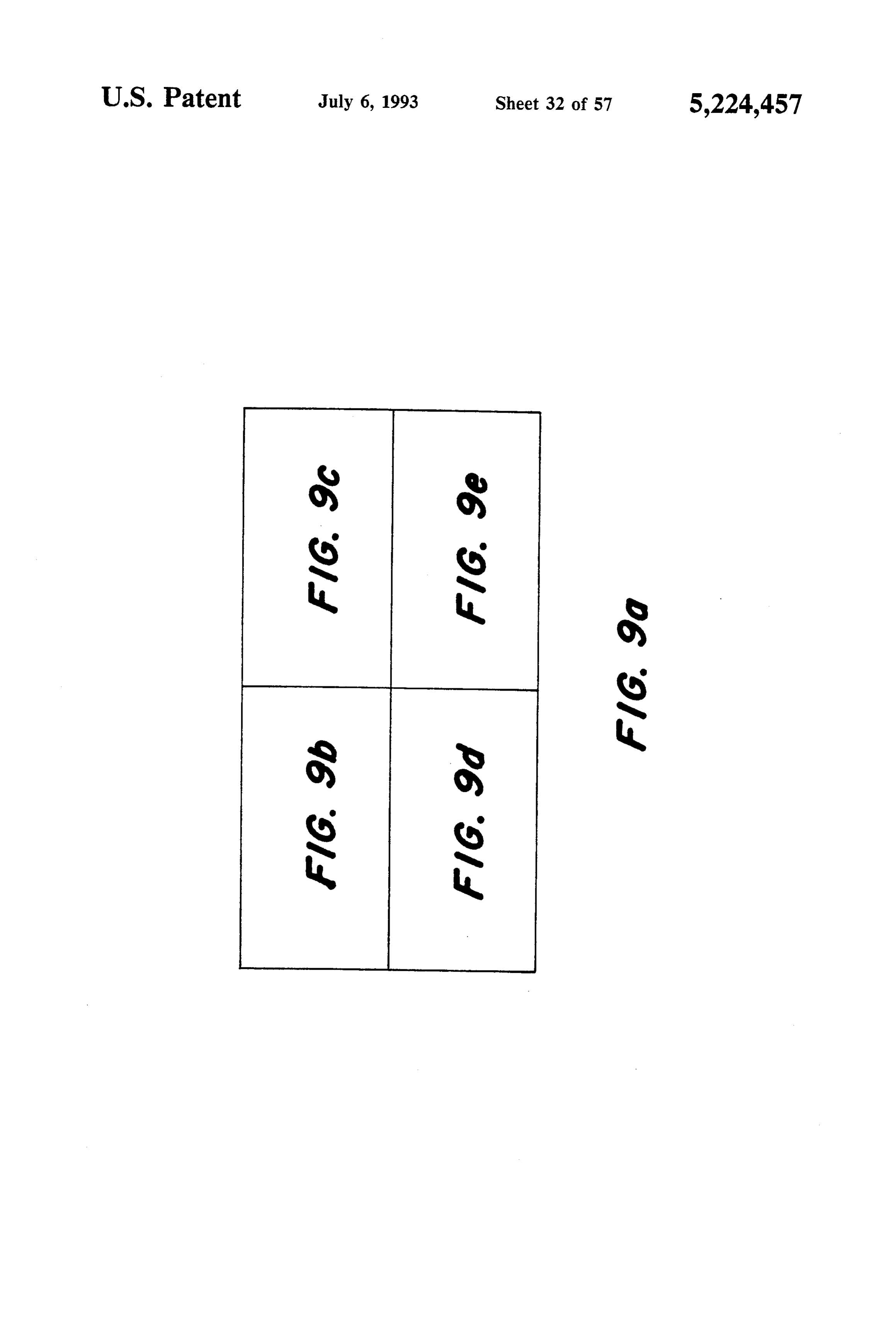
7. The RPMin (0-5 VDC TTL) signal, 10 pulses per ISO is partitioned into 13 functional blocks and some engine revolution, is the engine speed signal from the associated "glue' logic:
ECU 34 auxiliary speed sensor. The Link Controller 1. RPM (FIG. 10).
user this signal to measure engine RPM. The RPM calculation circuit takes the auxiliary speed 8. MCLK (12.8 kHz) is a master clock signal, gener 5 sensor input from the diesel ECU 34 (10 pulses per ated externally, which clocks the majority of the PGA engine revolution, 0-5 VDC, TTL) and calculates a control circuitry. 10-bit engine RPM value (RPM(9:0)), which is used to 9. MCLK4 (800 Hz) is a clock signal, generated exter address the link controller 40 Lookup tables. nally, used to ramp the diesel throttle (% Throttle) 2. Fuel Select (FIG. 11).
when switching from dual fuel to diesel fuel. O The fuel select circuit has several functions. At powe 10. MCLK8 (50 Hz) is a clock signal, generated exter rup the system defaults to diesel operation mode. If the nally, used to ramp the % Speed setpoint from 0 to the link controller 40 diagnostics (FIG. 13) determines that captured value. conditions are OK for dual fuel operation, this circuit 11. MCLK10 (12.5 Hz) is a clock signal, generated 5 allows the user to select diesel fuel or dual fuel modes. externally, used to ramp the diesel throttle when If conditions do not permit dual fuel operation (such as switching from diesel fuel to dual fuel. This clock signal low NG pressure) this circuit will disable dual fuel also determines the rate of user speed adjustments. operation. This could result in a forced return to diesel. 12. MCLK14 (0.78 Hz) clock signal, generated exter In all cases this circuit also controls the selection of nally, used to clock the link controller timer circuits. diesel ECU 34 torque limiting function (Torque) and 13. NGV30 is the output signal from the NG Valve NG3. Solenoid enable/disable (which controls valve 26).
position feedback comparator (not shown), and pro vides an indication of engine load while operating on The Torque circuit monitors the Torque output of dual fuel. the fuel select circuit (FIG. 11) and the outputs of the The following inputs are latched: Thrload circuit (FIG. 15) to control the ECU 34 25 Torque Select O/P FETs.
1. NGO, NG1, NG2, NG3, NG4, NG5, NG6, and 4. Diagnostic (FIG. 13).
NG7 are 8-bit Speed Setpoint values from an EPROM
Lookup table, used to provide a speed setpoint to the engine diagnostics
The load. NG circuit monitors the engine speed, pressure and intake air temperature governor 36 at switchover to dual fuel. and determines if conditions are OK for dual fuel opera The following are buffered outputs: 30 tion. The result is output via a single control line (Dual 1. Torque and Torque2 are ECU 34 Torque limiting FuelOK). Engine speed is actually monitored by the select lines which select one of three torque curves SpeedComp circuit (FIG. 14) and engine load by a which are programmed into the ECU 34 (see FIG. 23). Thrload150 circuit (FIG. 15) which pass their result to 2. A Solenoid output enables or disables the NG the diagnostic circuit.
supply solenoid valve 26. 35 The diagnostic circuitry implements a 1.25 second 3. A10 is a control line for address bit A10 of a lookup time delay filter in detecting any changes in the fault table which makes available position limit values with status of the dual fuel engine. This means that any fault both the normal and boost diesel pilot quantities, must be present or absent for 1.25 seconds in order for 4. A11 is a control line for address bit A11 of a lookup it to be detected. Also, when operating on dual fuel, the table which makes position limit values for engines with speed and NG Valve Position faults are flagged as a different horsepower ratings. critical errors. Therefore, if either of these two faults 5. Limitctl is a control line for an output enable (OE) occur the link controller 40 disallows dual fuel opera line of an NGLimit Lookup Table which permits the tion. A system reset is required to permit dual fuel oper link controller 40 to tri-state the lookup table outputs at On.
when running on diesel fuel. Pull down resistors at the 45 5. SpeedComp (FIG. 14).
lookup table output force 100% 9%. Limit value during The Speed comparison circuit compares the engine diesel fuel operation (no NG). speed with two internally set pre-determined speed The following are latched outputs: Settings to determine if it is less than these two values. 1. DLamp is the diesel lamp control line. During diesel operation, the link controller 40 monitors 2. DFLamp is the dual fuel lamp control line. 50 when the engine speed is less than 1400 RPM (this dis 3. THRO, THR1, THR2, THR3, THR4, THR5, ables Switchover to dual fuel), while during dual fuel THR6 and THR7 are a 8-bit throttle value sent to the operation it monitors when the engine speed is less than diesel ECU 34. These digital values are converted to 1200 RPM (this forces a return to diesel). 0.5–4.5 VDC analog voltages by a DAC0830 digital-to 6. Thrload 150 (FIG. 15).
analog converter (U7 of FIG. 6). 55 The comparator circuit used to provide an indication 4. RPMO, RPM1, RPM2, RPM3, RPM4, RPM5, of engine load. The circuit compares the throttle value RPM6, RPM7, RPM8 and RPM9 are a 10-bit RPM set by the operator with internally programmed con value calculated by the link controller 40 from the stant values for 40% and 80% load. The outputs THR40 RPMin input signals and are used to address EPROM and THR80 are then used by the Diagnostic circuit Lookup tables (U4, U5 of FIG. 6). (FIG. 13), the Torque circuit (FIG. 12) and to control 5. NGSO, NGS1, NGS2, NGS3, NGS4, NGS5, the A10 output address bit.
NGS6 and NGS7 are an 8-bit speed setpoint value sent 7. Speed Change (FIG. 16).
to the governor 36. These digital values are converted The speed change circuit detects when the operator to 4-8 VDC analog voltages by a DAC0830 digital-to has selected a speed adjustment during dual fuel opera analog converter (U6 of FIG. 6). 65 tion (by toggling Switch 52) and forces a return to diesel Referring now to FIG. 9, this schematic is a func fuel operation, where the speed adjustment is made by tional block diagram for the PGA of the link controller changing the throttle signal (%. Throttle) to the ECU element ISO of FIG, 8. The link controller 40 element 34. There is a 2.5 second time delay filter implemented
Page 65
before returning to dual fuel operation following any The Speedramp circuit ramps the NG Speed setpoint speed adjustments. (NGS(7:0)) from 0% to the latched speed setpoint value 8. LampDriver (FIG. 17). (NGSet(7:0)).
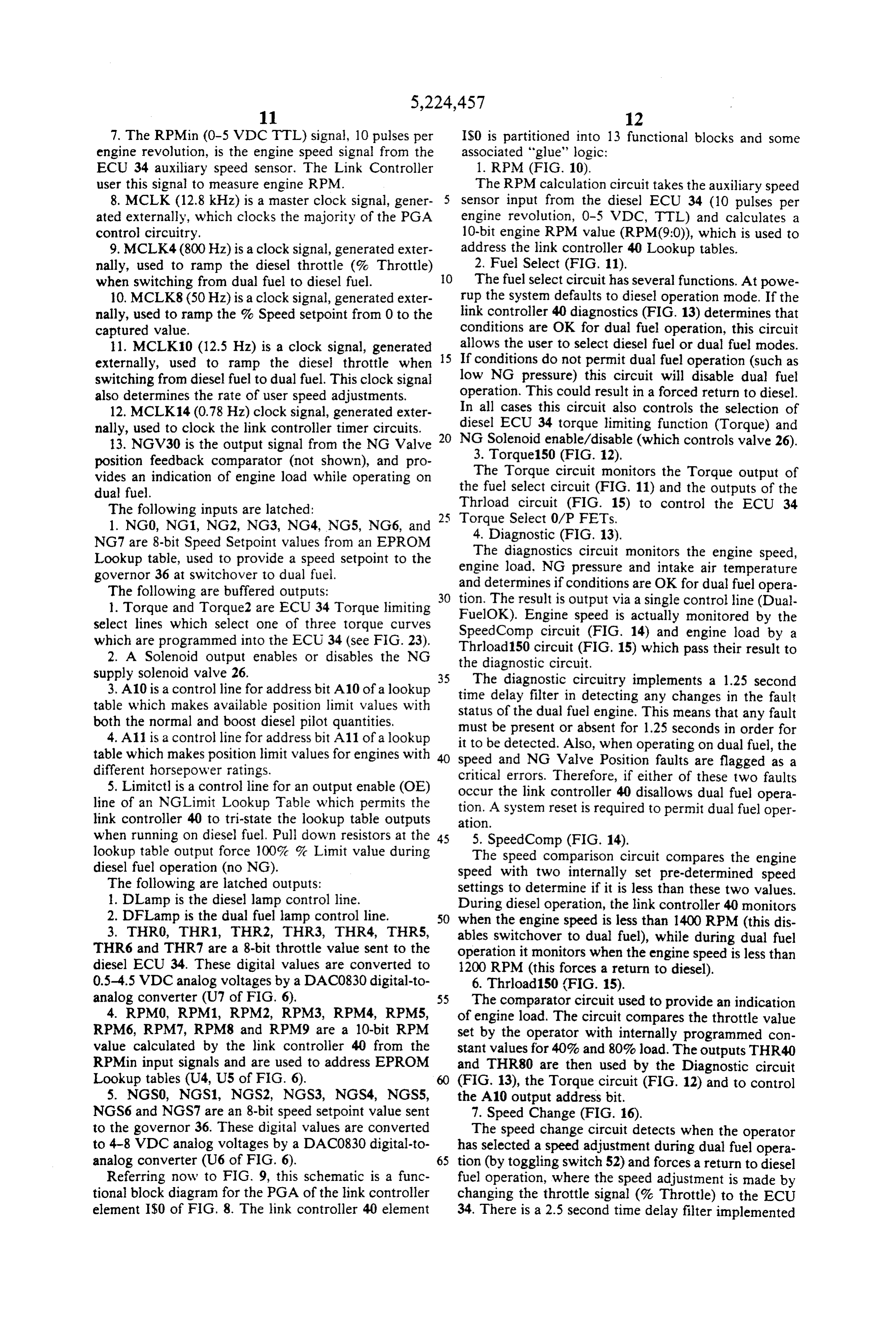
The lampdriver circuit controls the state of the Diesel 15. NG SpeedComp (FIG. 24).
lamp 56 and the Dual Fuel lamp 50. The lamps are 5 The speed setpoint comparator circuit compares the illuminated for 5 seconds at power-up as a test feature. NG Speed value (NGS(7:0)) with the latched speed Following this the lamps indicate the status of the sys setpoint (NGSet(7:0)). Once these two values are equal, tem as follows: the NG SpeedComp circuit signals the Speedramp cir
cuit to stop ramping up.
Diesel Dual Fuel Engine Status Referring now to FIG. 10, this schematic diagram represents the RPM calculation circuitry of the link
ON OFF diesel operation controller 40 (element (IS2) of FIG. 9). The input ON FLASH user select dual fuel switchover to dual fuel disabled (RPMin) from the ECU 34 auxiliary speed sensor is a OFF ON dual fuel operation 15 0-5 VDCTTL signal (10 pulses per engine revolution) FLASH ON switchover to diesel fault and the output is a 10-bit RPM value (RPM(9:0)), used to address Lookup tables on the link controller 40 PCB.
9 and 10. Throtset (FIG. 18), Rampset (FIG. 19). This circuit counts the time required for 40 RPM input The throtset and rampset circuitry work together to pulses and uses this value to address the Lookup tables. control the throttle signal to the diesel ECU 34. The (C10BCRD)counter
8-bit digital throttle value (THR(7:0)) is converted to a counter outputcounts
40 RPM pulses and sets the decade 1. This transition latches the RPM 0.5-4.5VDC analog voltage by the DAC0830 digital-to count (RPMCLK) from the 12-bit binary counter analog converter (U7).
At power-up (diesel mode), the user can increase or 25 itself (TC=0) and it counts to 40decade
again.
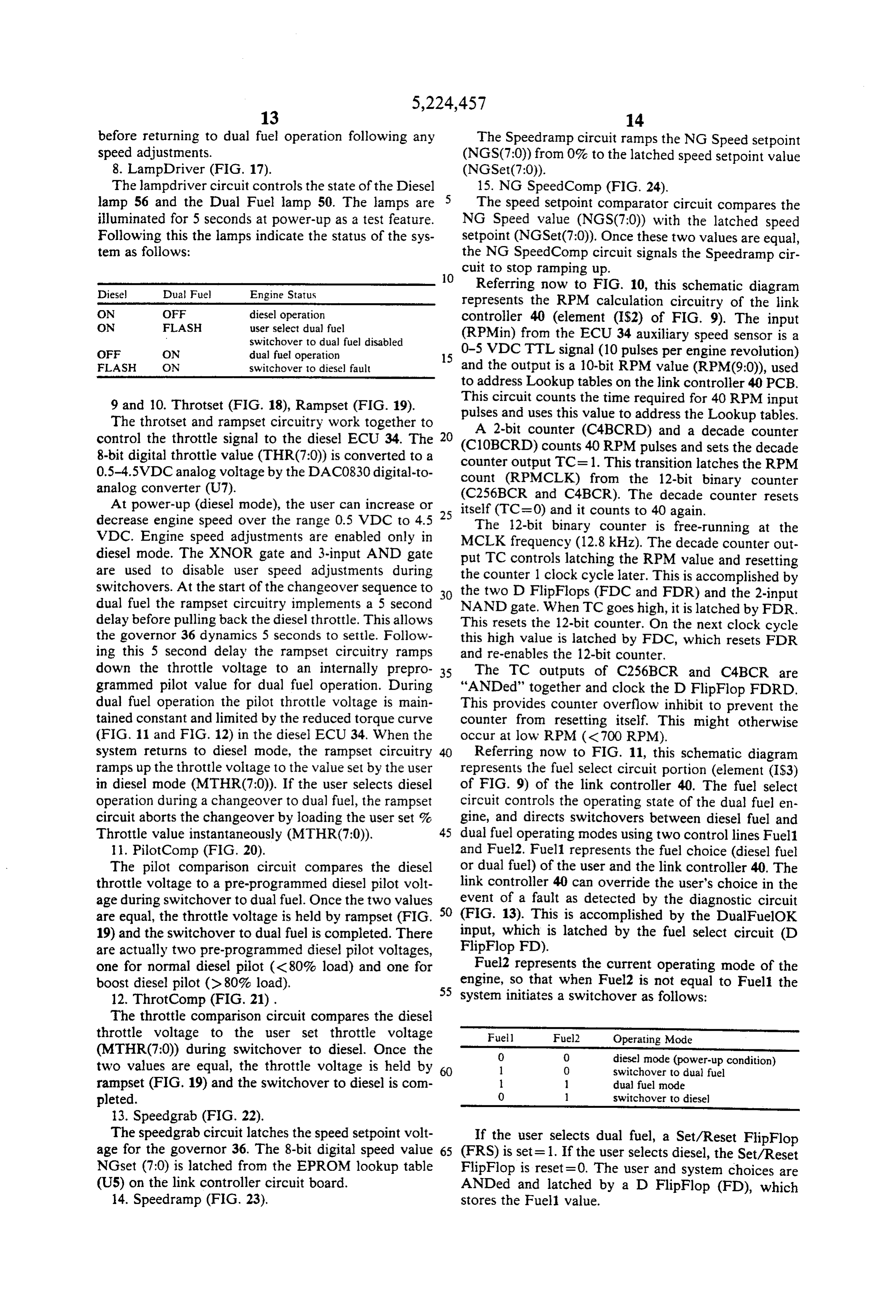
counter resets decrease engine speed over the range 0.5 VDC to 4.5 The 12-bit binary counter is free-running at the VDC. Engine speed adjustments are enabled only in MCLK frequency (12.8 kHz). The decade counter out diesel mode. The XNOR gate and 3-input AND gate put TC controls latching the RPM value and resetting are used to disable user speed adjustments during the counter 1 clock cycle later. This is accomplished by switchovers. At the start of the changeover sequence to the two D FlipFlops (FDC and FDR) and the 2-input dual fuel the rampset circuitry implements a 5 second 30 NAND gate. When TC goes high, it is latched by FDR. delay before pulling back the diesel throttle. This allows This resets the 12-bit counter. On the next clock cycle the governor 36 dynamics 5 seconds to settle. Follow this high value is latched by FDC, which resets FDR ing this 5 second delay the rampset circuitry ramps and re-enables the 12-bit counter, down the throttle voltage to an internally prepro 35 The TC outputs of C256BCR and C4BCR are grammed pilot value for dual fuel operation. During "ANDed" together and clock the D FlipFlop FDRD. dual fuel operation the pilot throttle voltage is main This provides counter overflow inhibit to prevent the tained constant and limited by the reduced torque curve counter from resetting itself. This might otherwise (FIG. 11 and FIG. 12) in the diesel ECU 34. When the occur at low RPM (< 700 RPM). system returns to diesel mode, the rampset circuitry Referring now to FIG. 11, this schematic diagram ramps up the throttle voltage to the value set by the user represents the fuel select circuit portion (element (IS3) in diesel mode (MTHR(7:0)). If the user selects diesel of FIG. 9) of the link controller 40. The fuel select operation during a changeover to dual fuel, the rampset circuit controls the operating state of the dual fuel en circuit aborts the changeover by loading the user set % gine, and directs switchovers between diesel fuel and Throttle value instantaneously (MTHR(7:0)). 45 dual fuel operating modes using two control lines Fuel1 11. PilotComp (FIG. 20). and Fuel2. Fuel1 represents the fuel choice (diesel fuel The pilot comparison circuit compares the diesel or dual fuel) of the user and the link controller 40. The throttle voltage to a pre-programmed diesel pilot volt link controller 40 can override the user's choice in the age during switchover to dual fuel. Once the two values 50 event of a fault as detected by the diagnostic circuit are equal, the throttle voltage is held by rampset (FIG. (FIG. 13). This is accomplished by the DualFuelOK 19) and the switchover to dual fuel is completed. There input, which is latched by the fuel select circuit (D are actually two pre-programmed diesel pilot voltages, FlipFlop FD).
one for normal diesel pilot (<80% load) and one for Fuel2 represents the current operating mode of the boost diesel pilot (>80% load). engine, so that when Fuel2 is not equal to Fuel the 55 system initiates a switchover as follows:
12. ThrotComp (FIG. 21).
The throttle comparison circuit compares the diesel throttle voltage to the user set throttle voltage Fuell Fuel2 Operating Mode (MTHR(7:0)) during switchover to diesel. Once the 0 O diesel mode (power-up condition) two values are equal, the throttle voltage is held by l O switchover to dual fuel rampset (FIG. 19) and the switchover to diesel is com l dual fuel mode pleted. O l switchover to diesel 13. Speedgrab (FIG. 22).
The speedgrab circuit latches the speed setpoint volt If the user selects dual fuel, a Set/Reset FlipFlop age for the governor 36. The 8-bit digital speed value 65 (FRS) is set=1. If the user selects diesel, the Set/Reset NGset (7:0) is latched from the EPROM lookup table FlipFlop is reset=0. The user and system choices are (US) on the link controller circuit board. ANDed and latched by a D FlipFlop (FD), which 14. Speedramp (FIG. 23). stores the Fuel value.
Page 66
The Fuel2 value is latched by a Set/Reset FlipFlop If the intake air temperature is greater than 53 C. (FRS). It is set = 1 by the link controller 40 at the termi (lntakeAir = 1 or NG pressure is less than 13 psi nation of a switchover to dual fuel and reset = 0 follow (LowNG = 1), then Dual FuelOK = 0, otherwise Dual ing a return to diesel fuel operation. These functions FuelOK is determined by engine speed, engine load and coincide directly with selecting the reduced ECU 34 the mode of operation.
torque curve (Set Fuel2) and throttle equal to user set In diesel operation (Fuel1=0, Fuel2=0), the link value (EQThrot=0, Reset Fuel2). controller 40 monitors if engine speed is less than 1400 If the user selects diesel during a switchover to dual RPM (S1400 = 1) or if engine load is less than 40% fuel (Fuel1 = 1, Fuel2=0), both Fuel 1 and Fuel2 are (THR40 = 1), while S1200 and NGV30 are disabled. If reset to 0 and the THRLoad output is set = 1 which 10 S1400 = 1 OR THR40 = 1 then Dual FuelOK-0. signals the Rampset circuit (IS7) to latch the user set % In dual fuel operation (Fuel1 = 1, Fuel2= 1), the link Throttle value (MTHR(7:0)). controller 40 monitors if engine speed is less than 1200 The Torque select and NG Solenoid enable values RPM (S1200 = 1) or if engine load is less than 30% are stored in D FlipFlop (FD). At powerup, both values (NGV30 = 1), while S1400 and THR40 are disabled. If are reset. The Torque value is set = 1 at the end of the 5 S1200 = 1 OR NGV30=1 then Dual FuelOK-0. switchover sequence when the EQPilot input makes a All Diagnostic faults are disabled during switchovers, high-to-low transition. It is reset=0 at the start of a since changes in throttle and NG Valve Position must switchover to diesel when EQPilot makes a low-to-high occur and must not be interpreted as a fault. Also, the transition. The Solenoid value is set = 1 at the start of a Diagnostic circuit implements a 1.25 second time delay switchover to dual fuel (when Fuel 1 is set = 1) and re 20 filter in detecting any changes in the fault status of the set=0 at the start of a switchover to diesel (when Fuel 1 dual fuel engine. The XOR gate close to the Dual is Reset=0). FuelOK output detects the change in the fault status The DFSelect output line indicates the users choice which enables the counter (C8BCRD) to count for 1.25 of operating mode (1 = Dual Fuel, 0= Diesel Fuel). seconds. If the change in fault status still exists, it is This output is used only by the LampDriver -circuit 25 latched by the Flip Flop (FDC) to the Dual FuelOK (FIG. 17) which flashes the dual fuel lamp 58 if dual fuel output.
operation has been selected by the user, but is not al The NG Valve Position fault (NGV30) or speed fault lowed by the link controller 40 due a detected fault (S1200) which can occur during dual fuel operation are (such as low NG pressure). interpreted as critical faults. Therefore, if this fault oc Referring now to FIG. 12, this schematic diagram 30 curs while operating on dual fuel, the link controller 40 represents the ECU torque select circuit portion (ele will force a return to diesel and not allow the system to ment (IS2282) of FIG. 9) of the link controller 40. The return to dual fuel. A 0.75 second time delay filter, torque select circuit monitors the Torque output from similar to the one described above, is also implemented the fuel select circuit (FIG. 11) and the THR40 and for monitoring NG Valve Position and speed during THR80 outputs of the Thrload circuit (FIG. 15) and 35 dual fuel operation.
controls the state of the ECU 34 torque select FETs Referring now to FIG. 14, this schematic diagram (Q1, Q5 in FIG. 6). This circuit selects normal rated represents Speed Comparison Circuit (element IS8 of torque curve for diesel fuel operation and either normal FIG. 9) of the link controller 40. The speed comparator diesel pilot (<80% load) or boost diesel pilot (>80% circuit compares the engine speed with two internally load) for dual fuel operation. set speed settings to determine if it is less than these two In connection with this torque curve selection func values.
tion, it was determined that a particular throttle setting Engine RPM is calculated by the RPM circuit (FIG. will correspond to a particular level of load on the 10) which addresses the two link controller 40 Lookup engine. This is because the throttle setting relates di tables. The NG% Speed setpoint Lookup table (U4 of rectly to the amount of fuel flowing to the engine, and 45 FIG. 6) provides a linear RPM output with approxi the amount of fuel determines how much load the en mately 5 RPM resolution.
gine can sustain at a particular speed. Also, the Throtset The 8-bit speed setpoint (NG(7:0)) is used by this circuit (FIG. 18) generates a MTHR value which repre circuit to monitor engine speed and the speedgrab cir sents a user selected throttle setting, and this MTHR cuit (FIG. 22) to provide a speed setpoint to the gover value is provided as an input to the Thrload circuit 50. nor 36.
(FIG. 15) which compares this throttle setting value to The speed comparator circuit uses a greater than/less a pair of threshold values. Thus, the Throtset circuit than (GLTGT) comparator tree to monitor the engine (FIG. 18), the Thrload circuit (FIG. 15) and the Torque RPM. The output of the speedcomp circuit is used by circuit (FIG. 12) cooperate together, and essentially the diagnostic circuit (FIG. 13).
operate to select the torque curve as a function of en 55 Referring now to FIG. 15, this schematic diagram gine load (as represented by the MTHR signal). More represents the Load Comparison Circuit (element particularly, during dual fuel operation, either torque I$2281 of FIG. 9) of the link controller 40. The load curve A or C is selected (viewing FIG. 25), depending comparison circuit monitors the diesel %. Throttle set upon the relationship of engine load to the threshold ting for comparison with two internally set values rep values. resenting 40% and 80% engine load. The outputs pro Referring now to FIG. 13, this schematic diagram vide an indication of how heavily the engine is loaded. represents the Diagnostic Circuit (element IS4 of FIG. The load comparison circuit uses a greater than/less 9) of the link controller 40. The diagnostic circuit moni than comparator tree (GLTGT) to monitor the two tors the status of sensors for engine speed, engine load, conditions.
intake air temperature and NG pressure and determines 65 Referring now to FIG. 16, this schematic diagram if conditions are OK for dual fuel operation. The result represents the Speed Change Detect Circuit (element is communicated via a single output control line Dual I$1301 of FIG. 9) of the link controller 40. The speed Fuel OK. change circuit detects when the operator has selected
Page 67
an increase or decrease in engine speed. If the engine is User speed adjustments (Increment and Decrement) operating in diesel fuel mode, the speed adjustment are enabled only in diesel mode (Fuel1 = 0, Fuel2=O) occurs instantaneously. If the engine is operating in dual via the clock enable (CE) line on the 8-bit counter (2- fuel mode, the speed change circuit flags the diagnostic C16BUDRD). This clock enable signal is also used by circuit (FIG. 13) to return to diesel operation, where the rampset circuit. The throttle output is the 8-bit value the speed adjustment is made. Once any speed adjust MTHR(7:0). At power-up the counter is reset to 00, ments are complete, the circuit will allow the link con which corresponds to diesel throttle voltage at idle. troller to return to dual fuel operation automatically External to throtset, the Increment and Decrement (unless diesel operation was manually selected, or con inputs pass through a logic AND gate to determine the ditions at the new speed are not suitable for dual fuel 10 value on the UpDown input.
operation as determined by the diagnostic circuit (FIG. The throtset circuit also contains logic to prevent the 13)). user from overflowing or underflowing the 8-bit In dual fuel mode (Fuel1 = 1, Fuel2= 1) there is no counter. It is imperative that the %. Throttle signal for delay in returning to diesel when a speed adjustment is the engine NOT go from 0% to 100% instantaneously made. Once the speed adjustment is complete there is a 15 or from 100% to 0%. If the counter counts up to FF or 2.5 second delay before returning to dual fuel. The 2.5 down to 00, its terminal count TC) signal will go high. second time delay filter is implemented with a 2-bit This will inhibit the count enable and force the throttle binary counter (C4BCRD) and provides a window of value to remain at the maximum or minimum value by time for minor speed adjustments in diesel mode. The setting one of the two D Flipflops (FDCRD). Only one speed change circuit is disabled during changeovers via D FlipFlop is enabled at a time, depending on whether the 2-input XNOR gate (XNOR2) fed by Fuel1 and the user counts up to maximum or down to minimum Fuel2. throttle.
Referring now to FIG. 17, this schematic diagram The throtset circuit is clocked by MCLK12, which represents the Lamp Driver Circuit (element IS5 of 25 allows the user to change % Throttle from 0% to 100% FIG. 9) of the link controller 40. The lamp driver cir in 80 seconds (MCLK12 is currently a 3.125 Hz clock). cuit controls the state of the diesel indicator lamp 56 and Referring now to FIG. 19, this schematic diagram the dual fuel indicator lamp 58. represents the throttle ramping or "rampset" circuit At power-up a 2-bit binary counter (C4BCRD) (element IS7 of FIG. 9) of the link controller 40. The counts up from 0 to 3 at a rate of 0.78 Hz. While it 30 rampset circuit works in conjunction with the throtset counts, the D FlipFlop at its output (FDC) is reset and circuit (FIG. 18) to control the throttle signal to the forces the two indicator lamps ON. Once the counter ECU 34. The throttle voltage sent to the ECU 34 is the reaches 3 (in 5 sec.), its terminal count line (TC) goes output of the rampset circuit (THR(7:0)), and so this high enabling the D FlipFlop to be Set = 1, which re value can be set by the user and ramped up and down moves the forced ON condition for the two lamps and during fuel switchovers.
disables the 2-bit counter. 35 User speed adjustments (Increment and Decrement) Once the forced ON condition is removed after pow are enabled only in diesel fuel mode (Fuel1=0- er-up, the lamps are controlled by three inputs from the Fuel2=0) via the clock enable output (CEin) of the fuel select circuit (FIG. 11). The lamps are forced ON throtset circuit to the clock enable line of the 8-bit by the Fuel2 input, and toggled or turned OFF via the 40 counter (2 Cl6BUDRD). At power-up, the counter is two T Flipflops with Reset (FTORD). A summary of reset to 00, which corresponds to the diesel throttle input/output is shown below (l=ON, T = toggle, voltage at idle. External to rampset, the Increment and 0=OFF): Decrement inputs pass through a logic AND gate to determine the value on the UpDown input.
Fuell Fuel2 DFSelect DLamp DFLamp Mode
The logic to prevent the counter from overflowing 45 and underflowing is contained in the throtset circuit and
diesel select dual fuel is similar to the corresponding logic described hereinbe l O O 1 switch to fore in connection with the throtset circuit. When oper dual fuel ating in diesel mode the throttle values MTHR(7:0) in 1 l O 1 dual fuel throtset and THRC7:0) in rampset are equal and are O T 1. select diesel 50 simultaneously adjusted by the user.
0 l T force to diesel At the start of switchover to dual fuel (Fuel1 = 1, Fuel2=0) the rampset circuit counts a 5 second delay before ramping down the diesel throttle (THR (7:0)).
Referring now to FIG. 18, this schematic diagram The start of switchover is determined by lower XOR2 represents the throttle control, or "throtset" circuit 55 gate in the schematic, which enables the 4-bit counter (element IS9 of FIG. 9) of the link controller 40. The (C16BCRD) to count for 5 seconds. Following the throtset circuit works in conjunction with the rampset delay, the signal to enable the throttle counter to count circuit (FIG. 19) to control the throttle signal to the down is latched by the Flip Flop FDCR. The 8-bit diesel ECU 34. The link controller 40 allows the user to counter counts down (with EQPilot = 1, UpDown=0) set the engine speed only in diesel operation. When the 60 until EQPilot is Reset=0 by the Pilotcomp circuit IS6). system switches over to dual fuel, the throttle voltage is EQPilot is Reset=0 when the throttle voltage ramped down to a predetermined pilot value and the THR(7:0) equals the internally set diesel pilot voltage. governor 36 adds NG to keep the engine at the desired User adjustments and EQThrot are disabled during the speed. When the system returns to diesel operation, the switchover to dual fuel.
link controller 40 must ramp the throttle voltage to the 65 However, if the user selects diesel during a switch user-set value before switchover to dual fuel occurred. over to dual fuel, the THRLoad input from the Fuel The purpose of the throtset circuit is to store the throt Select circuit (IS3) enables Rampset to load the user set tle voltage set by the user. % Throttle value (MTHR(7:0)).
Page 68
During dual fuel operation (Fuel1 = 1, Fuel2= 1) the to dual fuel. The speed setpoint is reset during diesel throttle voltage is held constant at the diesel pilot volt fuel operation by the 2-input AND gate (AND2B). age. User adjustments, EQThrot and EQPilot are dis Referring now to FIG. 23, this schematic diagram abled, but any user adjustments detected by the speed represents the NG Speedramp circuit (element IS2581 change circuits (IS1381) would force a return to diesel of FIG. 9) of the link controller 40. NG Speedramp operation. circuit ramps up the NG % Speed setpoint from 00 During switchover to diesel fuel operation (Fuel1 = 0, (Hex) to the speed setpoint value latched from the Fuel2= 1) the 8-bit counter is enabled to count up (via NGSpeed lookup table (U4) on the Link Controller EQThrot=1, UpDown = 1) until EQThrot is Reset = 0 circuit board. Ramping up the % Speed setpoint pre by the ThrotComp circuit (FIG. 21). EQThrot is Re vents the NG governor 36 from "kicking' the rotary set=0 when the throttle voltage THR(7:0) equals the actuator 38 to wide open throttle at the start of a user-set throttle voltage for diesel-only operation changeover to dual fuel.
MTHR(7:0). User speed adjustments and EQPilot are The speedramp circuit consists of an 8-bit binary disabled. up-down counter (2-Cl6BUDRD) with an asynchro The MCLKp 12.8 kHz clock frequency is used to 15 nous reset. At the start of a switchover to dual fuel load MTHR(7:0) if the operator aborts dual fuel (Fuel1 = 1, Fuel2=0, EQSpeed = 1) the counter is en changeover. The MCLK4800 Hz clock frequency is abled to count up at a rate of 50 Hz. This means that the used to ramp up diesel throttle on switchover from dual circuit will count from 00 (Hex) to FF (Hex) in 5 sec fuel to diesel fuel. The MCLK11 6.25 Hz clock fre onds, before the diesel %. Throttle begins ramping quency is used to ramp down diesel throttle on switch 20 down. Once the % Speed value (NGS(7:0) equals the % over to dual fuel. The MCLK12 3.125 Hz clock fre Speed setpoint, the NGSpeedcomp circuit (IS2582) quency is used to allow user to adjust throttle from to forces EQSpeed=0 which disables the updown counter 100% in 80 seconds. and causes it to hold its present value. On returning to Referring now to FIG. 20, this schematic diagram diesel operation (Fuel1=0, Fuel2=0) the speedramp represents the pilot comparison "pilotcomp" circuit 25 CICult S reset, (element IS6 of FIG. 9) of the link controller 40. The Referring now to FIG. 24, this schematic diagram pilotcomp circuit compares the diesel throttle voltage represents the NG Speedcomp circuit (element IS2582 to a preprogrammed programmed diesel pilot voltage of FIG. 9) of the link controller 40. The NGSpeedcomp during switchover to dual fuel and outputs EQPilot = 1 circuit compares the NG 7% Speed value (NGS(7:0)) when throttle is not equal to pilot, and EQPilot=0 30 with the desired NG 7% Speed setpoint (NGSet(7:0)) when throttle is equal to pilot. The pilotcomp circuit during a switchover to dual fuel operation and outputs has diesel pilot values programmed for normal (K80% EQSpeed = 1 when NGS(7:0) is not equal to load) and boost (>80% load) pilot conditions, with the NGSet(7:0) and outputs EQSpeed =0 when NGS(7:0) is appropriate value selected by the THR80 input from equal to NGSet (7:0).
the THRLoad circuit (IS2281). 35 The NGSpeedcomp circuit uses a greater than/less Referring now to FIG. 21, this schematic diagram than comparator tree (GLTGT) to compare each bit of represents the diesel throttle comparison "throtcomp" the 8-bit values to give EQSpeed.
circuit element IS11 of FIG. 9) of the link controller 40. Mode of Operation The throtcomp circuit compares the diesel throttle volt age (THR(7:0)) to the user-set throttle voltage At power up, the ECU 34 momentarily illuminates (MTHR(7:0)) during not equal to MTHR(7:0), and the amber Fault lamp 54 on the operator's panel, as a EQThrot=0 when THR(7:0) equal to MTHR(7:0). The test feature. Upon start-up, the link controller 40 de throtcomp circuit uses greater than /less than compara faults to diesel operation and the ECU 34 manages the tor tree (GTLT) to compare each bit of the 8-bit values engine starting procedure as for a normal diesel engine. to give EQThrot. 45 The link controller 40 selects the normal torque curve Referring now to FIG. 22, this schematic diagram and generates a 0%. Throttle signal to idle the engine. represents the speedgrab circuit (element IS10 of FIG. At power-up, the link controller 40 illuminates the 9) of the link controller 40. The speedgrab circuit pro diesel lamp 56 and the dual fuel lamp 58 for 5 seconds as vides the speed setpoint voltage to the governor 36. a test feature, after which only the diesel lamp 56 re There is no user speed adjustment allowed while oper SO mains on. The solenoid of the NG shut-off valve re ating on dual fuel; the speedgrab circuit simply latches mains off and the link controller 40 provides a 0% an 8-bit speed setpoint value (NG(7:0)) from the link Speed setpoint and 100% Limit to the governor 36 to controller 40 % Speed setpoint lookup table (U4 of ensure that the rotary actuator 38 closes the metering FIG. 6) and outputs this (NGSet(7:0)) for comparison valve 30.
with the NG SPeed setpoint output (NGS(7:0)) from 55 After starting, the operator may change the engine the Speedramp circuit (IS2581). If a user speed adjust speed via the speed control switch 52 on the operator's ment is detected by the speed change circuit (IS1381), panel 42. The fuel pump 14 must be operating when the link controller 40 forces a return to diesel operations adjusting the engine speed because the throttle signal is where the speed change is made. On returning to dual a fuel set point for the ECU 34. The engine must be fuel operation the speedgrab circuit would latch the connected to the load and operating under normal load new speed setpoint value. conditions for proper adjustment of speed when operat The speedgrab circuit consists of an 8-bit loadable ing on diesel. This is because the % Throttle signal is a register (RD8CR) which latches the NGSpeed setpoint fuel setpoint for the ECU 34. The link controller 40 will value at the start of a switchover to dual fuel (Fuel1 = 1, ramp the throttle signal sent to the ECU 34, at a fixed Fuel2=0). The two D Flipflops (FDR and FDC) and 65 rate in response to the + speed and - speed inputs 2-input NAND gate are used to generate a 2-clock from switch 52, accelerating and decelerating the en cycle load enable signal, which ensures that only one gine 12. Operator speed adjustments are possible only in speed setpoint value is latched at the start of switchover diesel operation, and not during fuel switchovers or
Page 69
dual fuel operation. If the system is running on dual fuel, shaded in FIG. 27). If NG flow were reduced by reduc the link controller 40 will automatically force a return ing maximum supply pressure for instance, the engine to diesel operation in order to adjust the engine speed. might operate within the safe area at low speeds, but at When any speed adjustments are complete, the engine higher speeds the engine would not produce adequate will be returned to dual fuel operation automatically power. By limiting the maximum position of the NG unless otherwise selected. With the ECU 34 governing valve at various speeds, dual fuel power can be limited as a fuel controller and the governor 36 governing as a to a value of approximately 5% greater than on diesel speed controller, this restriction ensures that for any fuel. This achieves safe dual fuel operation over a wide system initiated switchovers in the absence of an opera range of speeds and full power operation is maintained. tor, the engine will continue to run at the same speed in 10 The changeover sequence from diesel to dual fuel is both diesel and dual fuel modes. illustrated by FIG. 28. The diesel lamp 56 is turned The operator selects dual fuel operation via the fuel OFF while the dual fuel lamp 58 is turned ON. The link select switch 50 on the operator's panel. If the present controller 40 monitors the engine speed and captures a operating conditions are suitable for dual fuel operation, speed setpoint voltage for the governor 36 representing the link controller 40 will initiate a switchover. If the 15 the same speed. At the same time, the link controller 40 operating conditions are not suitable for dual fuel opera opens the NG supply solenoid valve 26 and enables the tion, the link controller 40 will continue to operate the limit voltage to the governor 36. The link controller 40 engine on diesel. The dual fuel indicator lamp 58 will implements a 5 second delay before ramping down the flash on and off to indicate that the operator has se % Throttle signal to the ECU 34. During this time, the lected dual fuel operation. When conditions are suitable 20 % Speed setpoint is ramped up from 0 to the captured for dual fuel operation the link controller 40 will auto value. This is to allow the governor 36 internal dynam matically switch to dual fuel, enabling the NG system ics time to adjust to the release of the % limit voltage, and extinguishing the diesel lamp 56. The operator can and permits the NG regulator 28 to stabilize the NG also abort a switchover to dual fuel operation by select supply pressure to the metering valve 30. ing diesel operation via the fuel select switch 50 on the 25 The % Throttle signal to the ECU 34 is ramped down operator's panel 42. from the user-selected value to a programmed diesel If, during dual fuel operation, engine speed changes pilot value. The %. Throttle signal is ramped down at a are made via the speed select switch 52, the system clock frequency of 6.25 Hz, which corresponds to a responds by automatically returning to pure diesel fuel time of 30 seconds to ramp %. Throttle from 100% to operation. Once the engine speed has been adjusted, the 25%. This slow ramping speed is required in order to system automatically returns to dual fuel operation at avoid a large speed drop during switchover. At this the new speed. point, the governor 36 assumes control of the engine As part of the dual fuel engine diagnostics, the link speed.
controller 40 monitors the intake air temperature sensor The link controller 40 selects the de-rated torque 20, the low NG pressure sensor and calculates engine 35 curve programmed into the ECU 34 representing the RPM and engine load to determine if conditions permit required diesel pilot quantity for dual fuel operation the engine 12 to be operated on dual fuel. under the given load conditions. This occurs when the With the engine 12 running on pure diesel fuel, the link controller 40 detects that the % Throttle signal has following conditions must exist for the link controller reached the programmed pilot value. 40 to allow dual fuel operation: dual fuel operation must Once the engine is operating on dual fuel, the opera be selected via fuel select switch 50, the NG supply tor can adjust the engine speed. The link controller 40 pressure must be greater than 18 psi (sensor switch 46 detects a speed change and forces a return to pure diesel open), the engine speed must be greater than 1400 fuel operation where the speed adjustment is made. RPM, the engine load must be greater than 40% as Once any speed adjustments are complete, the link con determined by the %. Throttle signal required by the 45 troller 40 automatically returns to dual fuel mode, un ECU, and the intake air temperature must be less than less diesel was manually selected.
53 C. (sensor switch 20 open). As part of the dual fuel diagnostics the link controller During dual fuel operation of the engine 12 the gov 40 will force a return to diesel if any one of the follow ernor 36 governs to a speed setpoint voltage provided ing conditions occur:
by the link controller 40. This signal corresponds to the 50 NG supply pressure < 13 psi (sensor switch 46 RPM at which the engine is running just prior to the closed), start of the changeover sequence. The speed values are OR engine speed (1200 RPM, generated by a look-up table in the link controller 40 OR engine load (30%, which contains speed setpoint versus RPM information. OR Intake Air Temperature>53 C. (switch sensor The governor 36 preferably has a % Speed setpoint 55 20 closed).
versus RPM characteristic within the limits shown in The operator can also force a return to diesel fuel FIG. 26. operation by selecting diesel operation using the fuel The link controller 40 also provides a % Limit signal select switch 50 on the operator's panel 24. to the governor 36 to prevent over-fueling of the dual The changeover sequence from dual fuel to diesel fuel engine at lower RPM. This allows the link control fuel operation is illustrated by FIG. 29. The dual fuel ler 40 to approximate the torque curve of the diesel lamp 58 is turned OFF while the diesel lamp 56 is engine 12. The limit signal is also generated by a limit turned ON. The link controller 40 selects the normal versus RPM look-up table in the link controller 40. torque curve in the ECU 34 and closes the NG supply FIG. 27 shows the NG fuel limiting requirement for solenoid valve 26. The %. Throttle signal to the ECU 34 safe engine operation and the limit versus RPM rela 65 is ramped up from the programmed diesel pilot quantity tionship programmed into the link controller 40. With to the value last set by the operator in diesel fuel mode. out this limiting feature, the engine power at lower The %. Throttle is ramped up at a clock frequency of speeds would exceed the safe area of operation (shown 800 Hz, which corresponds to a time of 255 milliseconds
Page 70
to ramp from 25% to 100%. This fast ramping speed is -continued required to avoid a large speed drop during switchover, re-r-terremierestamaa-ana
as the NG supply is shut off. At this point, the ECU 34 Reference Description Temp, Tolerance
re-assumes control of the engine 12.
The % Speed setpoint to the governor 36 is reset to 4 5 Cl2,C}9.C21, 1 F Capacitor -40° C./- 100° C. V and the 9% Limit signal is set to 100%. This ensures that the metering valve 30 is closed during diesel fuel C25,C26,C27 10 F -55 C./-- 105 C. - 10% - operation. Capacitor 50% If a diagnostic fault (e.g. high intake air temperature D1, D2, D3, Signal Diode - 40 C./-- 85 C. 5% or low NG pressure) forces a return to pure diesel fuel O operation, the dual fuel lamp 58 will flash on and off and D9, D10, Dll, Schottky Diode - 40 C/--85 C. h5% the diesel lamp 56 is turned on. If the detected fault later D12, d13, disappears, the link controller 40 will return the engine D14, D15,
12 to dual fuel operation. The lamps would then indi D18 5.1 V, 225 mW -40 C./--85 C. 5% cate dual fuel operation. 15 Zener
If the user selected a return to diesel, the dual fuel D19,020 8.7 V, 225 mW -40 C.M.--85 C. 5% lamp 58 is extinguished and the diesel lamp 56 is turned Zener
O. Zener
It should be mentioned that the link controller 40 ED22 5.6 W, 225 mW - 40 C.M.--85 C. 59. diagnostic circuitry implements a 1.25 second time 20 Zener delay filter for detecting any changes in the fault status J1 30-pin
Connector
of the dual fuel engine. This means that any fault must Ll,L2,L3, LA, Ferrite Beads -40 C.A.--85 C. 5% be absent or present for at least 1.25 seconds for it to be detected by the link controller 40. Also, the speed and 25 PGA Xilinx PGA -40 C./+85 C. Digital load faults during dual fuel operation are latched as Q1.Q2.O3,O4,
FET
critical faults. Therefore... the occurrence of one of these Q6 PNP Transistor -40 C.A.--85 C. faults would disallow any return to dual fuel operation R1,R2,R3,R4, 22K Resistor -55 C.M-125 C. 1% without a power-down or system reset. A 0.75 second time delay filter is implemented in the detection of these R7.R8,R9. 1. K Resistor -55 C.A.- 25 C. 1% faults.
The link controller 40 software controls the selection R12, Rl5.R16, OK Resistor - 55 C./- 125° C. 19. of the appropriate one of the ECU 34 torque curves shown in FIG. 25. The boost pilot curve A is selected if the engine 12 is operating over 80% load. Under heavy 35 R58,R65, and load conditions, the additional diesel fuel in the dual fuel mixture helps to cool the diesel injectors and prevent R14 4.02K Resistor -55 C/- 25 C. C. nozzle sooting. Under 80% load the minimum de-rated R18,R19.R2, 9.09K Resistor -55 C/- 25 C. 1% pilot curve C is used to minimize fuel operating costs. R24,R25,R63, OOK Resistor -55 C.M-125 C. 1. While the invention has been described in conjunc tion with a specific embodiment, it is to be understood R3 4.87M Resistor --55 C/- 25 C. 19. that many alternatives, modifications, and variations R32,R33 464K Resistor -55 C.A. 125 C. 1%
will be apparent to those skilled in the art in light of the R40 18.7K Resistor -55° C.A.L. 125° C. le. foregoing description. For example, a microprocessor R4 21.5K Resistor -55 C.A.-- 125 C. % could replace the PGA and its serial PROM, the 45 R55 R52,R53,R54, 30 ohn
Resistor
EPROMs and the oscillator circuitry. Alternatively, R56,R57 Slohm Resistor -55 C./- 125° C. although such an alternate design would require a much R59,R60,R6 2K Resistor -55 C.7-125 C. 1% larger circuit board and would lack the flexibility of a R62, R66 51. K Resistor -55 C.A.-- 125 C. 19. programmable device, the link controller could be built RT, RT2 TOR THERMIS- - 40 C./-- 85 C. NA with discrete IC components since the PGA integrates a large number of discrete functions into a single custom 50 Ul Schmitt Trigger -55" C./+ 125 C. Digital IC. Accordingly, this invention is intended to embrace U2 Switch
Debouncer
all such alternatives, modifications, and variations U3 5 V Regulator - 40 C.A.- 25 C. 59.
which fall within the spirit and scope of the claims U6,U7,U8 EPROM -40 C./+85 C. Digital which are appended hereto following the part list. Digital-analog -40' C./--85' C. 1/2LSB Converter
The following is a parts list of the components in 55 U9 Serial PROM -40 C./+85 C. Digital cluded in the circuits of FIGS. 5, 6, and 7, it being U10, U11 10 V Regulator -40 C./--85 C. 5% understood that the particular parts may be varied with U2 Oscillator/
Divider
out departing from the scope of this invention. U13 Comparator -40 C./+85 C. Analog
Reference Description Temp. Tolerance "treaterineralleesonianslam
C7, C8, C10, Capacitor We claim:
1. A dual fuel system for an engine having a liquid 65 fuel Supply, a source of gaseous fuel, and a controller
C30 coupled to the supply, to the source and to the engine, C3,C4.C9, .01 uF -550° C.A.- OO C. t20% the controller operating the engine in a first mode C36.C37,C38, Capacitor wherein it is supplied with liquid fuel only and in a
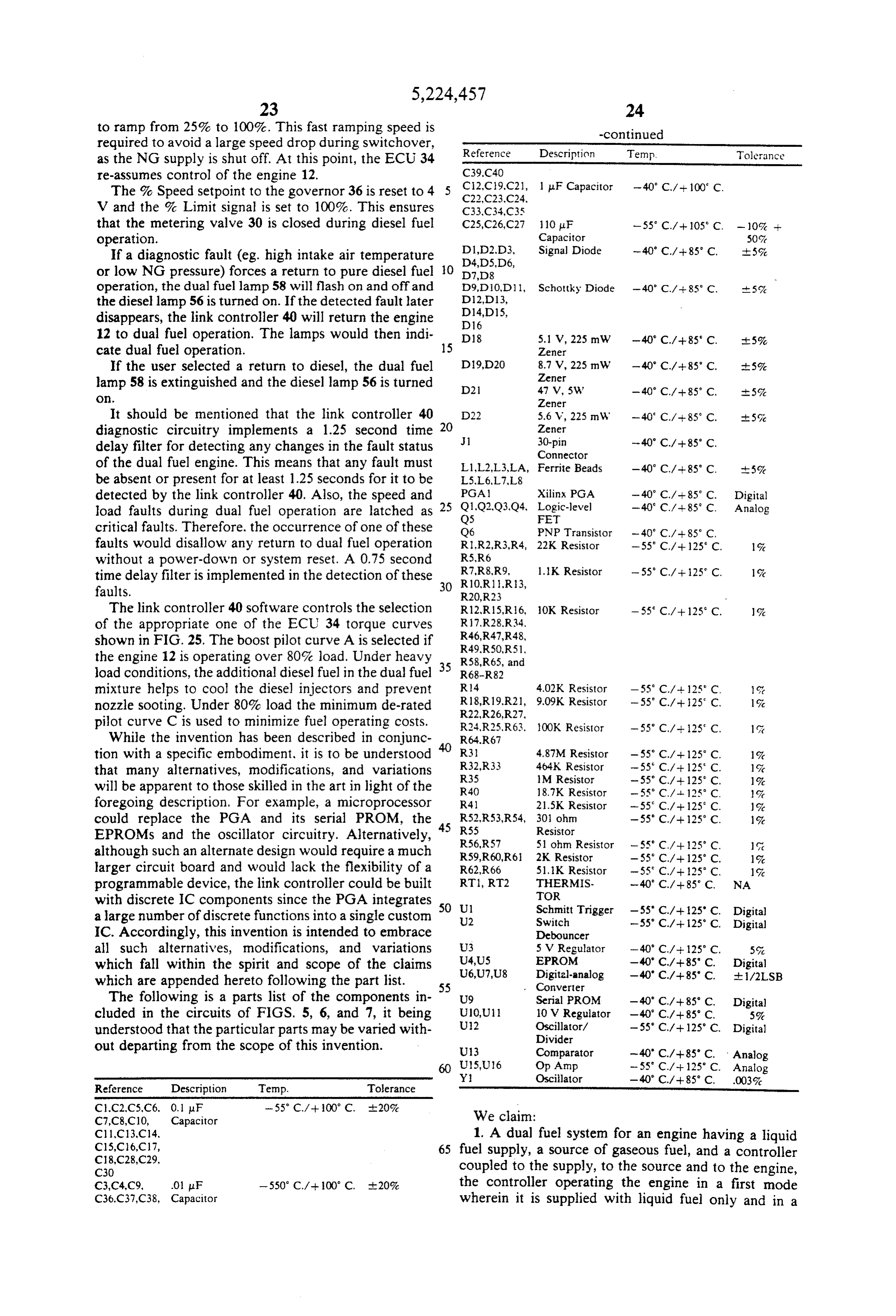
Page 71
second mode wherein it is supplied with both liquid and and in a second mode wherein it is supplied with both gaseous fuel, characterized by: liquid and gaseous fuel, characterized by: an engine speed sensor generating a speed signal rep an air temperature sensor for sensing the temperature resenting a rotation speed of the engine; and of engine intake air; and the controller comprising means responsive to the 5 the controller comprises means responsive to the speed signal for maintaining engine speed during sensed air temperature for automatically prevent dual fuel operation substantially the same as the ing conversion of the engine from liquid to dual engine speed during liquid fuel operation. fuel operation if the sensed air temperature is 2. A dual fuel system for an engine having a liquid greater than a certain temperature. fuel supply, a source of gaseous fuel, a fuel select com 10 5. A dual fuel system for an engine having a liquid mand device having a first position for commanding fuel supply, a source of gaseous fuel, and a controller liquid fuel operation of the engine and having a second coupled to the supply, to the source and to the engine, position for commanding dual liquid and gaseous fuel the controller operating the engine in a first mode operation of the engine, and a controller responsive to wherein it is supplied with liquid fuel only and in a the fuel select command device for operating the engine 5 second mode wherein it is supplied with both liquid and in a first mode wherein it is supplied with liquid fuel gaseous fuel, characterized by:
only and in a second mode wherein it is supplied with an air temperature sensor for sensing the temperature both liquid and gaseous fuel, characterized by: of engine intake air; and an engine speed sensor generating a speed signal rep the controller comprises means responsive to the resenting a rotation speed of the engine; and 20 sensed air temperature of automatically converting the controller comprises means responsive to the the engine from dual fuel operation to liquid opera engine speed signal for automatically preventing tion if the sensed air temperature is greater than a conversion of the engine from liquid to dual fuel certain temperature.
operation if the sensed engine speed is less than a 6. A dual fuel system for an engine having a liquid certain speed. 25 fuel supply, a source of gaseous fuel, and a controller 3. A dual fuel system for an engine having a liquid coupled to the supply, to the source and to the engine, fuel supply, a source of gaseous fuel, a fuel select com the controller operating the engine in a first mode mand device having a first position for commanding wherein it is supplied with liquid fuel only and in a liquid fuel operation of the engine and having a second second mode wherein it is supplied with both liquid and position for commanding dual liquid and gaseous fuel 30 gaseous fuel, characterized by:
operation of the engine, and a controller responsive to an operator adjustable speed command device gener the fuel select command device for operating the engine ating a signal representing a desired increase or in a first mode wherein it is supplied with liquid fuel decrease in operating speed of the engine; and only and in a second mode wherein it is supplied with the controller comprises means for receiving the both liquid and gaseous fuel, characterized by: 35 signal from the speed command device and for means for generating a load signal representing a load automatically converting the engine from dual fuel on the engine; and operation to liquid fuel operation in response to the controller comprises means responsive to the load adjustment of the speed command device to in signal for automatically preventing conversion of crease the operating speed of the engine and also in the engine from liquid to dual fuel operation if the 40 response to adjustment of the speed command de engine load is less than a certain load. vice to decrease the operating speed of the engine. 4. A dual fuel system for an engine having a liquid 7. The invention of claim 6, wherein the link control fuel supply, a source of gaseous fuel, a fuel Select com ler comprises:
mand device having a first position for command liquid means for detecting completion of an adjustment to fuel operation of the engine and having a second posi 45 the engine speed; and tion for commanding dual liquid and gaseous fuel opera Ineans for automatically converting the engine back tion of the engine, and a controller responsive to the to dual fuel operation in response to the completion fuel select command device for operating the engine in of an adjustment to the engine speed. a first mode wherein it is supplied with liquid fuel only sk sk k ak sk
Provenance
- Collection
- Cited prior art
- Original PDF
- patentimages.storage.googleapis.com →
- Filed
- 1992-02-28
- Pages
- 71
- Method
- pdftotext (the PDF's own text layer) + pdftoppm 300dpi page scans
- Source
- Google Patents bibliographic record
- Granted
- 1993-07-06
- Inventors
- Jeff Arsenault; Wendelin Goetz; James Larocque; Deere and Co
- Transcribed from
- patentimages.storage.googleapis.com →