patent · US10066838
Dual fuel heating system
4 September 2018
Page 1 — bibliographic record
MAIMULTAMINHA CUI LINTUL MIODI MINI
United States Patent (10) Patent No.: US 10 ,066 ,838 B2 (45) Date of Patent: Sep . 4 , 2018 (54 ) DUAL FUEL HEATING SYSTEM (2015.04 ); Y1OT 137/87129 (2015 .04 ); Y1OT
(71) Applicant: David Deng, Diamond Bar, CA (US) (2015 .04 ); Y1OT 137 / 87917 (2015 .04 ) (72) Inventor: David Deng, Diamond Bar, CA (US) (58 ) Field of Classification Search CPC . . ......... F23C 1 /08 ; F23C 1 /00 ( * ) Notice : Subject to any disclaimer, the term of this USPC .................................... 431/280, 285; 126 / 77 patent is extended or adjusted under 35 See application file for complete search history . U . S .C . 154 (b ) by 307 days . References Cited
(21) Appl. No.: 14/859,202 U . S . PATENT DOCUMENTS (22 ) Filed : Sep . 18 , 2015 660,948 A 10 / 1900 Carlisle
(65 ) Prior Publication Data (Continued )
FOREIGN PATENT DOCUMENTS
Related U . S . Application Data CA 2391757 1/ 2003 (63 ) Continuation of application No. 14 /311, 091, filed on CN 2421550 2 /2001 Jun . 20 , 2014 , now Pat. No . 9 , 140 ,457 , which is a (Continued ) ( Continued )
OTHER PUBLICATIONS
F24C 1/02 ( 2006 .01) Consumer Guide to Vent- Free Gas Supplemental Heating Products, F16K 11 /083 (2006 .01) est. 2007 .
F23C 1/08 ( 2006 .01 ) ( Continued )
F23K 5 / 06 ( 2006 .01) Primary Examiner — Avinash Savani F23N 1/ 00 (2006 .01) (74 ) Attorney, Agent, or Firm - Innovation Capital Law (Continued ) Group , LLP; Vic Lin (52 ) U .S . CI. (57) ABSTRACT
(2013 .01); F23C 1/08 (2013.01); F23K 5 /005 A dual fuel heating system can be used in a gas appliance . ( 2013.01); F23K 5 /06 (2013.01); F23N 1/007 A dual fuel heating system can have a fuel selector valve for (2013 .01); F24H 3 /006 ( 2013 .01) ; F24H selecting between a first fuel and a second fuel different from 9 / 1881 ( 2013 . 01 ); F23N 2035 /18 ( 2013 .01); the first. The dual fuelheating system can include a regulator F23N 2037 /02 (2013 .01); F23N 2037/08 unit configured to regulate the pressure of the two different ( 2013 . 01) ; Y10T 137 / 86501 (2015 . 04 ); YIOT fuels. The selector valve determines which flow path for 137 /86541 (2015 .04 ); Y10T 137 / 86566 which fuel is open and which is closed .
137 /86823 (2015 .04 ); Y1OT 137 /86831 20 Claims, 44 Drawing Sheets
SODSPACE
EZ EZZIZTEITITZ
Page 2
US 10 ,Page
Related U . S . Application Data 3 , 590 , 806 A
continuation of application No. 12 / 797, 451, filed on 3 , 800 ,830 A 4 /1974 Etter Jun . 9 , 2010 , now Pat. No . 8 ,757 , 139 . 3 ,814 ,570 A 6 / 1974 Guigues et al.
(60) Provisional application No .61/ 221,521, filed on Jun . 3 , 829 ,279 A 8 / 1974 Qualley et al. 29 , 2009, provisional application No. 61/ 221,520 , 3 , 843, 107 A 10 / 1974 Atkins filed on Jun . 29 , 2009 , provisional application No . 3 ,843 ,310 A 10 / 1974 Massi
61/ 221,529, filed on Jun . 29, 2009, provisional 3 ,884 ,413 A 5 / 1975 Berquist application No. 61/ 221,528 , filed on Jun . 29 , 2009, 3 ,902,316 A 9 / 1975 Huellmantel provisional application No. 61/287 , 147 , filed on Dec. 3 ,909, 188 A
16 , 2009 , provisional application No. 61/ 286 , 355 , 3 , 967,590 A 7 / 1976 Hays et al. filed on Dec . 14 , 2009, provisional application No . 3 ,989 ,064 A 11/ 1976 Branson et al. 61/ 286 , 354 , filed on Dec . 14 , 2009, provisional 3 , 989, 188 A 11/ 1976 Branson application No. 61 /286 ,352 , filed on Dec . 14 , 2009 , 4 ,007, 760 A 2 / 1977 Branson et al . provisional application No. 61/304,373 , filed on Feb . D243 ,694 S 3 / 1977 Faulkner
12 , 2010 . 4 ,010 ,728 A
(51) Int . CI. 4 , 076 ,011 A 2 / 1978 Proulx
F24H 3 /00 ( 2006 .01) 4 ,085 ,720 A * 4 / 1978 Etoh FO2M 13 /06 F24H 9 / 18 ( 2006 .01) 123/ 179 . 16
( 56 ) References Cited 4 , 108 , 144 A 8 /1978 Wilhoite
U . S . PATENT DOCUMENTS 4 , 141,505 A 2 / 1979 Reichelderfer
743,714 A 11/ 1903 Guese 4 , 184 ,473 A 1/ 1980 McIntire et al. 1, 051,072 A 1/ 1913 Bradley 4 ,217 , 869 A 8 /1980 Masaki
1 ,216 , 529 A 2 / 1917 Wilcox 4 ,249 , 886 A 2 /1981 Bush 1 ,327 , 252 A 1 / 1920 Paulson 4 , 282, 855 A 8 / 1981 Perry 1 ,465, 292 A 8 /1923 Wessig 4 , 290 ,450 A 9 / 1981 Swanson 1 ,589 , 386 A 6 / 1926 Harper 4 , 301, 825 A 11/ 1981 Simko 1 ,639 ,115 A 8 / 1927 Smith 4 ,312 , 372 A 1 / 1982 Amos et al . 1 ,639,780 A 8 / 1927 Mulholland 4 ,329 , 137 A 5 / 1982 Werne 1 ,707 ,007 A 3 / 1929 Harper 4 , 340 , 362 A 7/ 1982 Chalupsky et al. 1 ,580 , 179 A 4 / 1929 Twombly 4 ,348 ,172 A 9 / 1982 Miller 1 , 860 , 942 A 5 / 1932 Morse 4 ,355 ,659 A 10 / 1982 Kelchner 1 ,867, 110 A 7 / 1932 Signore 4 ,359 ,284 A 11/ 1982 Kude et al. 1 , 961,086 A 5 / 1934 Sherman et al. 4 ,373 , 507 A 2 / 1983 Schwartz 2 ,054 ,588 A 9 / 1936 Stephens 4 ,386 ,599 A 6 / 1983 Berryhill 2 ,095, 064 A 10 / 1937 Harper 4 ,465 ,456 A 8 / 1984 Hynek et al. 2 ,108,299 A 2 / 1938 Steffen 4 ,474 , 166 A 10 / 1984 Shaftner et al. 2 , 120 , 864 A 6 / 1938 Kagi 4 ,502 ,453 A * 3 / 1985 Kabasin .............. FO2D 19 /0655 2 , 132 ,020 A 10 / 1938 Forster 123 / 1 A
2 , 161,523 A 6 / 1939 Moecker, Jr. et al. 4 ,509,912 A 4 / 1985 Van Berkum 2 ,319 ,676 A 5 / 1943 Guelson 4 ,574 ,763 A 3 /1986 Hallberg 2 ,380 ,956 A 8 / 1945 Evarts 4 ,597 ,733 A 7 / 1986 Dean et al . 2 ,422, 368 A 6 / 1947 Ray 4 ,614 , 168 A 9 / 1986 Batchelor 2 ,423,682 A 7 / 1947 Castle 4 ,637 ,429 A 1/ 1987 Dietiker et al. 2 ,443, 892 A 6 / 1948 Caparone 4 ,640 ,680 A 2 / 1987 Schilling 2 ,497,486 A 2 / 1950 Barber 4 ,686 , 891 A 8 /1987 Pouchard 2 ,518,894 A 8 / 1950 Humbarger et al. 4 ,718 ,448 A 1 / 1988 Love et al. 2 ,520 ,591 A 8 / 1950 Wilmarth 4 ,718 ,846 A 1/ 1988 Oguri et al. 2 , 556 ,337 A 6 / 1951 Paille 4 ,768 ,543 A 9 / 1988 Wienke et al. 2 ,630 ,821 A 3/ 1953 Arey et al. 4 , 768, 947 A 9 /1988 Adachi 2 ,652 ,225 A 9 / 1953 Peterson et al. 4 ,782 ,814 A 11/ 1988 Cherryholmes 2 ,661, 157 A 12 / 1953 Reichelderfer 4 ,793 ,323 A 12 / 1988 Guida et al. 2 ,672,735 A 3 / 1954 Jones et al. 4 ,796 ,652 A 1/ 1989 Hafla 2 ,687 , 140 A 8 / 1954 St. Clair et al. 4 ,836 ,668 A 6 / 1989 Christianson 2 , 747 ,613 A 5 / 1956 Reinhart 4 ,838 ,241 A 6 / 1989 Rieger 2 ,796 , 506 A 6 / 1957 Lumbert 4 , 848 , 133 A 7 /1989 Paulis et al. 2 ,905, 361 A 9 / 1959 Noall 4 ,848 ,313 A 7 / 1989 Velie 2 ,949 ,524 A 8 / 1960 Scarioni 4 , 850 , 530 A 7 / 1989 Uecker 2 ,986 , 002 A 5 / 1961 Ferri 4 , 874 ,006 A 10 / 1989 Iqbal 3 , 001, 541 A 9 / 1961 St. Clair et al. 4 ,930 ,538 A 6 / 1990 Browne 3 ,001,547 A 9 / 1961 Brumbaugh 4 ,957 ,085 A 9 / 1990 Sverdlin 3 ,032 ,096 A 5 /1962 Stoul 4 , 962,749 A 10 / 1990 Dempsey et al. 3 , 139 ,879 A 7 / 1964 Bauer et al. 4 , 965, 707 A 10 / 1990 Butterfield 3 , 177,794 A 4 / 1965 Laing 4 , 999 ,792 A 3 / 1991 Anderson et al. 3 ,244 , 193 A 4 / 1966 Loveless 5 , 000 , 162 A 3 / 1991 Shimek et al. 3 ,295, 585 A 1 / 1967 Kovach , Jr. et al . 5 , 025 ,990 A 6 / 1991 Ridenour 3 ,331,392 A 7 / 1967 Davidson et al. 5 ,027, 854 A 7 / 1991 Genbauffe 3 , 387 ,600 A 6 / 1968 Terzian 5 ,090 ,899 A 2/ 1992 Kee 3 ,417 ,779 A 12/ 1968 Golay 5 , 107 ,821 A 4 / 1992 von Blanquet 3, 430 ,655 A 3 / 1969 Forney 5 , 172 ,728 A 12 / 1992 Tsukazaki
Page 3
(56 ) References Cited 6 ,607 , 854 B1
U . S . PATENT DOCUMENTS 6, 779,333 B2 8/ 2004 Gerhold
5 , 193,746 A 3 / 1993 Iwamura et al. 6, 843, 244 B2 1/ 2005 McCalley et al. 5 ,239,979 A 8/ 1993 Maurice et al. 6, 845,966 B1 1 /2005 Albizuri 5 , 243 ,963 A 9 / 1993 Riener 6, 848, 441 B2 2 / 2005 Bachinski et al. 5 ,249, 567 A 10 / 1993 Maitland et al. 6 , 884, 065 B2 4 /2005 Vandrak et al. 5 , 251,066 A 10 / 1993 Appelbaum 6 , 901, 962 B2 6 /2005 Kroupa et al. 5 , 251 ,823 A 10 / 1993 Joshi et al. 6 ,904 , 873 B1 6 /2005 Ashton 5 ,278,936 A 1 / 1994 Shao 6 , 910, 496 B2 6 / 2005 Strom 5 ,278, 966 A 1/ 1994 Parks et al. 6 , 928, 821 B2 8 / 2005 Gerhold 5 , 301, 825 A 4 / 1994 Scala et al. 6 , 938, 634 B2 9 /2005 Dewey 5 , 379 ,794 A 1 / 1995 Brown 6 , 959, 144 B2 10 /2005 Shimonoma 5 ,380, 956 A 1 / 1995 Loo et al. 7 ,013, 079 B2 3/ 2006 Ito et al. 5 ,397, 233 A 3 / 1995 Eavenson et al. 7 ,013, 886 B2 3 /2006 Deng 5 ,413, 141 A 5 / 1995 Dietiker 7, 044 ,729 B2 5 /2006 Ayastuy 5 ,437,304 A 8 / 1995 Delcroix 7 ,048, 538 B2 5 /2006 Albizuri 5 ,452,709 A 9 / 1995 Mealer 7 ,156,370 B2 1/2007 Albizuri 5 ,458 ,294 A 10 / 1995 Zachary et al. 7 ,174 , 912 B2 2 /2007 Lowe 5 ,470 ,018 A 11/ 1995 Smith 7 ,174 ,913 B2 2 /2007 Albizuri 5 ,513 , 798 A 5 / 1996 Tavor 7 ,201,186 B2 4 / 2007 Ayastuy 5 ,542 ,407 A 8 / 1996 Hawkinson 7 ,251,940 B2 8 /2007 Graves et al. 5 ,542 ,609 A 8 / 1996 Myers et al. 7 , 255,100 B2 8 /2007 Repper et al. 5 ,553,603 A 9 / 1996 Barudi et al. 7 , 258, 285 B1 8 / 2007 Combs et al. 5 , 567, 141 A 10 / 1996 Joshi et al. 7 ,299 ,799 B2 11/2007 Albizuri 5 ,584 ,680 A 12/ 1996 Kim 7 , 300, 278 B2 11/ 2007 Vandrak et al. 5 ,591 ,024 A 1 / 1997 Eavenson et al. 7 , 367 ,352 B25 /2008 Hagen et al. 5 ,603,211 A 2 / 1997 Graves B2 6 /2008 Zielinski et al. 5 ,630 ,821 A 5 / 1997 Klass 7 ,422, 011 B2 9/ 2008 Bachinski et al. 5 ,642 ,580 A 7 / 1997 Hess et al. 7 , 434, 447 B2 10 /2008 Deng
5 ,645 ,043 A 7 / 1997 Long et al. 7 ,458,386 B2 12/2008 Zhang 5 ,674 , 065 A 10 / 1997 Grando et al. 7 ,487, 888 B1 2 / 2009 Pierre, Jr . 5 ,712 , 728 A 1/ 1998 Chen 7 ,490 , 869 B2 2 /2009 Iturralde et al. D391 , 345 S 2 / 1998 Mandir et al. 7 ,528,608 B2 5 / 2009 Elexpuru et al. 5 ,782 ,626 A 7 / 1998 Joos et al. 7 , 533 , 656 B2 5 /2009 Dingle 5 , 787 ,874 A 8 / 1998 Krohn et al. 7 ,591 ,257 B2 9 /2009 Bayer et al. 5 , 787 ,928 A 8 / 1998 Allen et al. 7 ,600,529 B2 10 / 2009 Querejeta 5 ,795, 145 A 8/ 1998 Manning et al. 7, 607,325 B2 . 10 / 2009 Elexpuru et al. 5 , 807,098 A 9 / 1998 Deng 7 ,607, 426 B2 10 / 2009 Deng 5 ,814 ,121 A 9 / 1998 Travis 7 , 634 ,993 B2 12 /2009 Bellomo 5 ,838,243 A 11/ 1998 Gallo 7 ,637, 476 B2 12 /2009 Mugica et al. 5 ,890, 459 A 4 / 1999 Hedrick et al. 7 ,641,470 B2 1/ 2010 Albizuri 5 , 906 , 197 A 5 / 1999 French et al. 7 , 651, 330 B2 1/ 2010 Albizuri 5 ,908, 066 A 6 / 1999 Rauch 7 ,654 , 820 B2 2 / 2010 Deng 5 ,915 , 952 A 6 / 1999 Manning et al. 7 , 677, 236 B2 3 / 2010 Deng 5 ,928,540 A 7 / 1999 Antoine et al. 7 ,699 ,334 B1 4 /2010 Mann et al.
5 ,931,661 A 8 / 1999 Kingery 7 ,730, 765 B2 6 /2010 Deng 5 ,937, 139 A 8 / 1999 Peterson et al. 7 , 758, 323 B2 7 /2010 Orue 5 ,941,699 A 8 / 1999 Abele 7 ,766, 006 B1 8 / 2010 Manning 5 , 966 ,937 A 10 / 1999 Graves 7 ,861, 706 B2 1/ 2011 Bellomo 5 , 971 ,746 A 10 / 1999 Givens et al. 7 ,901,204 B2 3 / 2011 Stephens et al. 5 ,975, 112 A 11/ 1999 Ohmi et al . 7 , 909, 601 B2 3/ 2011 Stephens et al. 5 ,980, 379 A 11/ 1999 Shibata 7 ,942,164 B2 5 / 2011 Hsiao 5 ,987,889 A 11/ 1999 Graves et al. 7 , 967 , 005 B2 6 / 2011 Parrish 5 , 988 ,204 A 11/ 1999 Reinhardt et al. 7 ,967, 006 B2 6 / 2011 Deng 6 ,006 , 743 A 12 / 1999 Shimek et al. 7 , 967, 007 B2 6 / 2011 Deng 6 ,027 ,335 A 2 /2000 Griffioen et al. 8 ,011, 920 B2 9 / 2011 Deng 6 ,035 ,893 A 3 / 2000 Ohmi et al. 8 ,057,219 B1 11/ 2011 Manning et al. 6 ,045 ,058 A 4 / 2000 Dobbeling et al. 8 ,075 ,305 B2 12/ 2011 Stephens et al. 6 , 068 ,017 A 5 /2000 Haworth et al. 8 ,104 ,258 B1 * 1/2012 Jansen . . . . . FO2C 7 /232 6 ,076 ,517 A 6 / 2000 Kahlke et al. 137 / 240 6 , 135, 063 A 10 / 2000 Welden 8, 152 ,515 B2 4 /2012 Deng 6 , 145, 502 A 11/ 2000 Lyons et al. 8 ,235,708 B2 8 /2012 Deng 6 , 162 ,048 A 12 / 2000 Griffioen et al. 8 ,241, 034 B2 8 /2012 Deng 6 , 210, 267 B1 4 / 2001 Long et al. 8 , 281, 781 B2 10 /2012 Deng 6 ,227 ,451 B15 / 2001 Caruso 8 , 297 ,968 B2 10 /2012 Deng 6, 237,588 B1 5 / 2001 Hawkinson 8,317, 511 B2 11/2012 Deng 6 ,244, 223 B1 6 / 2001 Welk 8 , 393, 138 B2 3 /2013 Hu 6 ,244, 524 B1 6 / 2001 Tackels et al. 8, 465,277 B2 6 /2013 Deng 6, 257,270 B1 7 / 2001 Ohmi et al. 8 , 506, 290 B2 8/ 2013 Deng 6 , 290, 361 B1 9 / 2001 Berzin 8 , 516, 878 B2 8 /2013 Deng 6, 293 ,784 B1 9 / 2001 Griffioen 8,517, 718 B2 8 /2013 Deng 6,327,427 B1 12/ 2001 Burkett 8, 545 , 216 B2 10 /2013 Deng 6 ,340 ,298 B11 / 2002 Vandrak et al. 8 , 568, 136 B2 10 / 2013 Deng 6,354 , 072 B1 3 / 2002 Hura 8 , 757, 139 B2 6 /2014 Deng 6 ,354, 078 B13 /2002 Karlsson et al. 8,757, 202 B2 6 / 2014 Deng 6 , 367, 239 B1 4 / 2002 Brown et al. 8, 764 ,436 B2 7 / 2014 Deng 6 ,543 ,235 B1 4 /2003 Crocker et al. 8 ,808 ,075 B2 8/ 2014 Gebke et al.
Page 4
( 56 ) References Cited 58 219320 A 12/ 1983
U . S . PATENT DOCUMENTS 62169926 7 / 1987
2002/0058266 A1 5 /2002 Clough et al. 05256422 5 /1993 2002/0160325 Al 10 /2002 Deng 10141656 5 / 1998 2002 /0160326 Al 10 / 2002 Deng 11192166 7 /1999 2003 /0010952 AL 1/2003 Morete 11193929 7 / 1999 2003 /0102025 A1 6 / 2003 Garcha 11 - 344216 12 / 1999 2003 /0217555 A1 11/2003 Gerhold 2000234738 8 / 2000 2004 /0109680 A 6 / 2004 Rinnai 2003 056845 A 2 /2003 2004 /0151480 AL 8 / 2004 Rinnai =
2004 /0159317 Al 8 /2004 Walther et al. 2003 074837 A 3 /2003 2004 /0226600 A 11/ 2004 Starer et al. 2003 074838 A 3 / 2003 2004 /0238030 Al 12/2004 Dewey , Jr . 2003 - 83537 3 /2003 2005 /0036770 Al 2 /2005 Ito et al. 2003- 90517 3 /2003 2005 /0053887 A1 3 /2005 Westergaard 200390498 3 /2003 2005 /0139209 Al 6 / 2005 Deng 2005257169 9 /2005 2005 /0167530 Al 8 / 2005 Ward et al. 2006029763 2 /2006 2005 /0202361 Al 9 / 2005 Albizuri JP 2007017030 1 / 2007 2005/0208443 Al 9 / 2005 Bachinski et al. JP 2010071477 4 /2010 2005/ 02 14705 A1 9 / 2005 Jaulent wo 02061336 8 /2002 2006 /0096644 Al 5 /2006 Goldfarb et al. WO WO 2008 /071970 6 /2008 2006 /0154194 Al 7 / 2006 Panther et al. WO 2008112933 9 /2008
2007 /0000254 A1 1/2007 Laster et al. OTHER PUBLICATIONS
2007/0154856 A1 7 / 2007 Hallit et al. Heat and Glo , Escape Series Gas Fireplaces, Mar. 2005.
2007 /0215223 Al 9 /2007 Morris Heat and Glo , Escape- 42DV Owner's Manual, Rev. i, Dec . 2006 . 2007 /0224558 A1 9 / 2007 Flick et al. International Search Report and Written Opinion for Application 2007/0277803 Al 12/ 2007 Deng No . PCT-US2008-056910 , dated Jul. 16 , 2008 . 2008 /0121116 AL 5 /2008 Albizuri International Search Report and Written Opinion for International 2008 /0153045 A 6 /2008 Deng Application No . PCT/US2010 /039668 , Notification dated Oct. 1 , 2008 /0168980 A1 7 / 2008 Lyons et al. 2010 .
2008/ 0227041 A1 9 / 2008 Kirchner et al. International Search Report and Written Opinion for International
2008/0236689 Al 10 / 2008 Albizuri Application No . PCT/US2010 /039687, Notification dated Oct. 5 , 2008/0237525 A1 * 10 /2008 Morris ............... FO2M 37/ 0023 2010 .
251/ 356 International Search Report and Written Opinion for International 2008 /0314090 A1 12/2008 Orue Orue et al. Application No. PCT/US2010 /039655 , Notification dated Jan . 14 , 2009 /0039072 AL 2 /2009 Llona 2011.
2009/0140193 Al 6 / 2009 Albizuri Landa International Search Report and Written Opinion for International 2009/0150050 A1 6 / 2009 Mashida et al. Application No. PCT/US2010 /039681, Notification dated Jan . 12 , 2009/0159068 AL 6 / 2009 Querejeta et al . 2011 .
2009 /0173075 A 7 /2009 Miura et al . Napoleon , Park Avenue Installation and Operation Instructions, Jul. 2009/ 0270023 Al 10 / 2009 Bartmann 20 , 2006 .
2010 / 0035195 A1 2 / 2010 Querejeta Andueza et al. Napoleon , The Madison Installation and Operation Instructions, 2010 /0086884 Al 4 / 2010 Querejeta Andueza et al. May 24 , 2005 .
2010 /0086885 Al 4 / 2010 Querejeta Andueza et al. International Preliminary Report on Patentability for International 2010 /0089385 Al 4 / 2010 Albizuri Application No. PCT/US2010 / 039655, Notification dated Oct. 14 , 2010 /0089386 A1 4 / 2010 Albizuri 2011 .
2010 / 0095945 Al 4 / 2010 Manning International Preliminary Report on Patentability for International 2010 /0154777 A1 6 / 2010 Carvalho et al. Application No. PCT/US2010 / 039668, Notification dated Oct. 14 , 2010 /0255433 A1 10 / 2010 Querejeta Andueza et al. 2011.
2010 /0275953 AL 11/ 2010 Orue Orue et al. International Preliminary Report on Patentability for International 2010 /0310997 Al 12 / 2010 Mugica Odriozola et al. Application No. PCT/US2010 /039681, Notification dated Oct. 14 , 2011/0143294 A1 6 / 2011 Deng 2011.
2011/0269390 AL 11 /2011 Pinkalla et al. International Preliminary Report on Patentability for International 2012/0031392 AL 2 / 2012 Deng Application No. PCT /US2010 / 039687 , Notification dated Sep . 20 , 2012 /0248359 Al 10 / 2012 Dederich et al. 2011.
2012 /0273070 A1 11/ 2012 Freers et al. European Search Report for European Application No. 07009672 . 2 2013 /0122439 AL 5 /2013 Deng dated Mar. 29 , 2012 .
2014 / 0045419 Al 2 / 2014 Bartmann Quite Fireplace Fan , How the Quite fireplace Fan Works in a Direct Vent Fireplace , http ://www .qtfpsfan . com /how _ it _ works.htm , Feb .
FOREIGN PATENT DOCUMENTS 17 , 2009 .
Procom Heating, Inc. v. GHP Group , Inc. (W . D . KY, Case No .
CN 2430629 Y 5 /2001 1 : 13 -cv - 001673 -GNS-HBB ): GHP ' s 2nd Amended Initial Invalid
ity Contentions, Claims Chart -Exhibit H , Sep . 4 , 2015 .
CN 1873268 12 /2006 Country Flame Technologies Inglenook Fireplace Gas Log Set
Model INGLS 24 - N or INGLS 24 -P Natural Gas or Propane
DE 720 854 C 5 / 1942 Conversion Kit , Installation , Operation , and Maintenance Manual, EP 0915295 5 / 1999 2004 .
EP 1970625 9 / 2008 Desa Heating Products , Technical Service Training Manual, 2004 . GB 2210155 6 / 1989 Flagro F -400T Dual Fuel Construction Heater, Operating Instruc JP 51114989 10 / 1976 tionsManual.
Page 5
US 10 ,Page
( 56 ) References Cited Installation Instructions and Owner 's Manuals for Empire Unvented Gas Fireplace Model VFHS- 32 , Aug. 2002 .
OTHER PUBLICATIONS Procom Heating, Inc. v. GHP Group , Inc. ( W .D . KY, Case No. 1 : 13 -cv - 00163-GNS -HBB ): GHP's Answer to the First Amended
Heat Wagon S1505 Construction Heater, Installation and Mainte Complaint, Aug. 27 , 2014 nance Manual, Jul. 29, 2002. Procom Heating, Inc. v. GHP Group, Inc . (W . D . KY, Case No. Jotul GF 3 BVAllagash B - Vent Gas Heater, Installation and Oper 1 : 13 - cv - 00163 -GNS -HBB ): Procom Heating 's First Amended ating Instructions, Dec. 2000 . Complaint, Aug. 13 , 2014 .
Vanguard Unvented ( Vent-Free ) Propane/LP Gas Log Heater Procom Heating , Inc . v. GHP Group , Inc. ( W . D . KY, Case No. Manual, Feb . 2004 . 1 : 13 -cv - 00163-GNS -HBB ): Claims Construction Memorandum White Mountain Hearth , The Vail Vent- Free Gas Fireplace, Instal Opinion and Order, Jul. 8 , 2015.
lation Instructions and Owner' s Manual, Mar. 2006 . Procom Heating, Inc. v. GHP Group , Inc. ( W .D . KY, Case No. Installation Instructions and Owner 's Manuals for Empire Unvented 1: 13 -cv -00163-GNS -HBB ): GHP' s Initial Invalidity Contentions, Gas Fireplace Model VFHS -36 , Mar. 2001. Mar. 31, 2014 .
Installation Instructions and Owner 's Manuals for Empire Unvented Procom Heating, Inc. v. GHP Group, Inc . (W . D . KY, Case No. Gas Fireplace Model VFHS -33 , Apr. 2001. 1 : 13 -cv -00163 -GNS -HBB ): GHP's 2nd Amended Initial Invalidity Installation Instructions and Owner 's Manuals for Empire Unvented Contentions, Sep . 4 , 2015 .
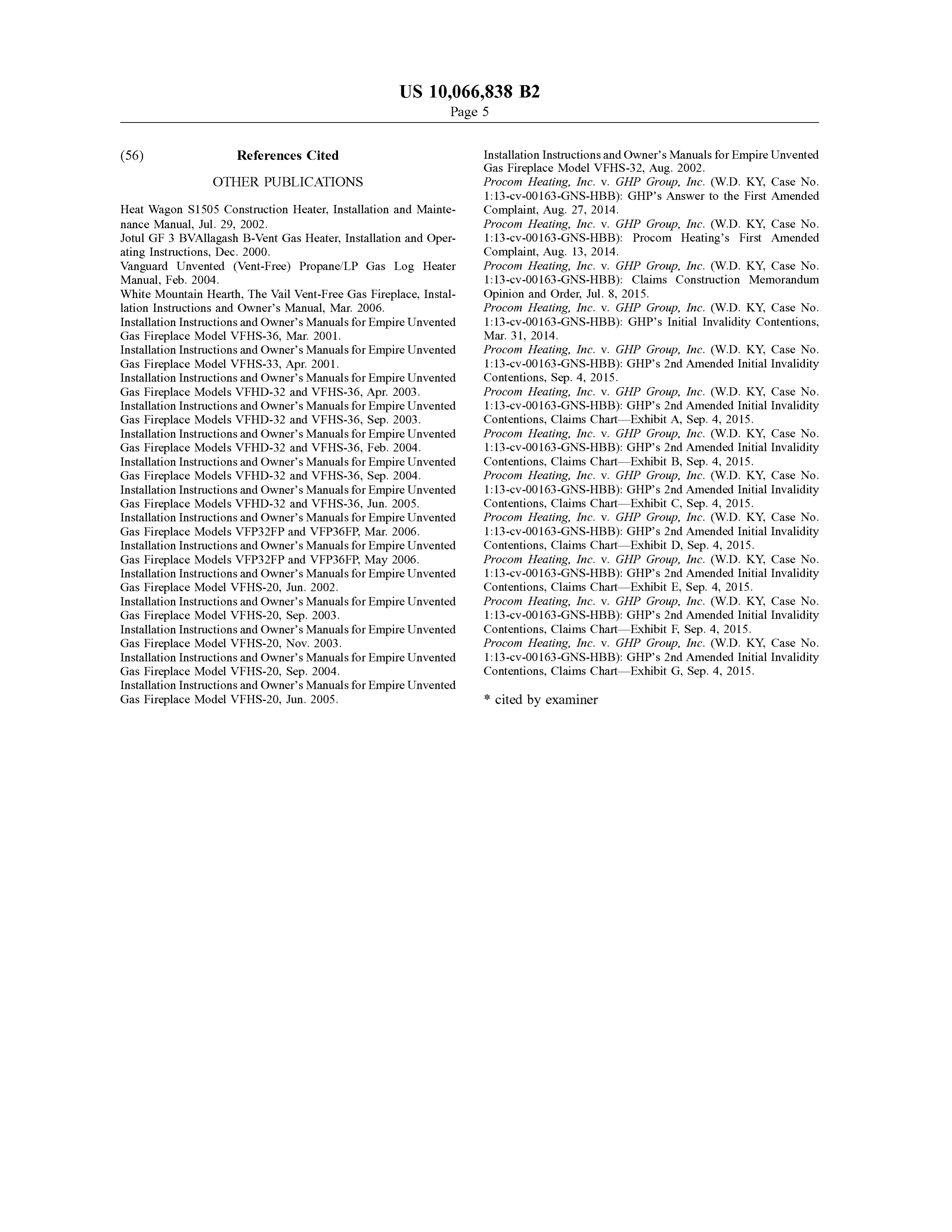
Gas Fireplace Models VFHD - 32 and VFHS -36 , Apr. 2003 . Procom Heating , Inc . V . GHP Group , Inc. (W .D . KY, Case No. Installation Instructions and Owner 's Manuals for Empire Unvented 1: 13 -cv -00163-GNS-HBB ): GHP' s 2nd Amended Initial Invalidity Gas Fireplace Models VFHD - 32 and VFHS -36 , Sep . 2003 . Contentions, Claims Chart — Exhibit A , Sep . 4 , 2015 . Installation Instructions and Owner 's Manuals for Empire Unvented Procom Heating, Inc . v. GHP Group , Inc. ( W .D . KY, Case No. Gas Fireplace Models VFHD - 32 and VFHS - 36 , Feb . 2004 . 1 : 13 - cv -00163 -GNS-HBB ): GHP 's 2nd Amended Initial Invalidity Installation Instructions and Owner 's Manuals for Empire Unvented Contentions, Claims Chart — Exhibit B , Sep . 4 , 2015 . Gas Fireplace Models VFHD -32 and VFHS- 36 , Sep . 2004 . Procom Heating, Inc . v. GHP Group , Inc. ( W .D . KY, Case No. Installation Instructions and Owner's Manuals for Empire Unvented 1 : 13 -cv - 00163-GNS-HBB ): GHP' s 2nd Amended Initial Invalidity Gas Fireplace Models VFHD - 32 and VFHS - 36 , Jun. 2005. Contentions, Claims Chart Exhibit C , Sep . 4 , 2015 . Installation Instructions and Owner 's Manuals for Empire Unvented Procom Heating , Inc . v. GHP Group , Inc . (W .D . KY, Case No. Gas Fireplace Models VFP32FP and VFP36FP , Mar. 2006 . 1 : 13 - cv - 00163 -GNS -HBB ): GHP ' s 2nd Amended Initial Invalidity Installation Instructions and Owner's Manuals for Empire Unvented Contentions, Claims Chart — Exhibit D , Sep . 4 , 2015 . Gas Fireplace Models VFP32FP and VFP36FP , May 2006 . Procom Heating , Inc . V . GHP Group , Inc . (W .D . KY, Case No. Installation Instructions and Owner 's Manuals for Empire Unvented 1: 13 -cv -00163 -GNS -HBB ): GHP 's 2nd Amended Initial Invalidity Gas Fireplace Model VFHS - 20 , Jun . 2002 . Contentions, Claims Chart — Exhibit E , Sep . 4 , 2015 . Installation Instructions and Owner's Manuals for Empire Unvented Procom Heating , Inc . V . GHP Group, Inc. ( W .D . KY, Case No. Gas Fireplace Model VFHS - 20 , Sep . 2003. 1 : 13 -cv -00163 -GNS -HBB ): GHP 's 2nd Amended Initial Invalidity Installation Instructions and Owner's Manuals for Empire Unvented Contentions, Claims Chart — Exhibit F , Sep . 4 , 2015 . Gas Fireplace Model VFHS - 20 , Nov . 2003. Procom Heating, Inc . v . GHP Group , Inc . (W .D . KY, Case No. Installation Instructions and Owner 's Manuals for Empire Unvented 1: 13 -cv - 00163 -GNS -HBB ): GHP 's 2nd Amended Initial Invalidity Gas Fireplace Model VFHS- 20 , Sep . 2004 . Contentions, Claims Chart — Exhibit G , Sep . 4 , 2015 . Installation Instructions and Owner's Manuals for Empire Unvented
Gas Fireplace Model VFHS- 20 , Jun . 2005 . * cited by examiner
Page 6
Drawing sheet — no readable text.
Page 7
Drawing sheet — no readable text.
Page 8
Drawing sheet — no readable text.
Page 9
Drawing sheet — no readable text.
Page 10
Drawing sheet — no readable text.
Page 11
Drawing sheet — no readable text.
Page 12
Drawing sheet — no readable text.
Page 13
Drawing sheet — no readable text.
Page 14
Drawing sheet — no readable text.
Page 15
Drawing sheet — no readable text.
Page 16
Drawing sheet — no readable text.
Page 17
Drawing sheet — no readable text.
Page 18
Drawing sheet — no readable text.
Page 19
Drawing sheet — no readable text.
Page 20
Drawing sheet — no readable text.
Page 21
Drawing sheet — no readable text.
Page 22
Drawing sheet — no readable text.
Page 23
Drawing sheet — no readable text.
Page 24
Drawing sheet — no readable text.
Page 25
Drawing sheet — no readable text.
Page 26
Drawing sheet — no readable text.
Page 27
Drawing sheet — no readable text.

Page 28
Drawing sheet — no readable text.
Page 29
Drawing sheet — no readable text.
Page 30
Drawing sheet — no readable text.
Page 31
Drawing sheet — no readable text.
Page 32
Drawing sheet — no readable text.
Page 33
Drawing sheet — no readable text.
Page 34
Drawing sheet — no readable text.
Page 35
Drawing sheet — no readable text.
Page 36
Drawing sheet — no readable text.
Page 37
Drawing sheet — no readable text.
Page 38
Drawing sheet — no readable text.
Page 39
Drawing sheet — no readable text.
Page 40
Drawing sheet — no readable text.
Page 41
Drawing sheet — no readable text.
Page 42
U .S . Patent Sep. 4,2018 Sheet 37 of 44 US 10,066,838 B2 16 1 * * * ** * R . HHH2XwON www ** * ww end link the arey e th what
m Wwwwwwwww
wwwwwwwwwwwwwwwwwwwww
Kanada
HititRR
Izi
WHO FIG.27B
ekic
stimu
HAAnywer * * * y
FIG
AFYT MY
Why
wwwwwwwwwwwwwwwwwwwwwwwwwww
Page 43
U . S . Patent Sep . 4 , 2018 Sheet 38 of 44 US 10 , 066 ,838 B2
the
FIG toisaimprimary man gem ngaruhiy mima tematike baptiem TY WWW
his istoran marre
FIG windsuitrey ndo
padapredah and maisonreligione *
ti h ti eiterbilgothinnin w
FIG
Page 44
Drawing sheet — no readable text.
Page 45
Drawing sheet — no readable text.
Page 46
Drawing sheet — no readable text.
Page 47
Drawing sheet — no readable text.
Page 48
Drawing sheet — no readable text.
Page 49
Drawing sheet — no readable text.
Page 50
DUAL FUEL HEATING SYSTEM interface surface wherein manipulation of said interface surface controls the amount of air flow and the type of gas
CROSS -REFERENCE TO RELATED to flow to the combustion chamber. In some embodiments , APPLICATIONS an axis of rotation of the air shutter control and an axis of 5 rotation of a gas pathway can be coincident. In some
This application is a continuation of U . S . patent applica - embodiments, the air shutter control can be configured to tion Ser. No. 14 /311 ,091 , filed Jun . 20 , 2014 , now U .S . Pat. allow for fine tuning adjustmentof the air shutter from either No . 9, 140,457 , which is a continuation of U .S . patent of the first or second positions .
application Ser. No. 12/797 ,451, filed Jun . 9 , 2010 , now U .S . Certain embodiments of an apparatus further comprise an Pat. No . 8 ,757 , 139 , which claims priority to U . S . Provi- 10 outlet valve that can control a flow of fuel to either a first sional Appl. Nos.: (1 ) 61/221,521, filed Jun . 29 , 2009 ; (2 ) ODS nozzle and first burner nozzle or a second ODS nozzle 61/221 .520 . filed Jun . 29 . 2009 ; (3 ) 61/221.529 , filed Jun . and second burner nozzle , wherein the first ODS nozzle and 29 . 2009: ( 4 ) 61/ 221. 528 . filed Jun . 29 . 2009 : (5 ) 61/ 287, first burner nozzle can be configured for the first fuel and the 147 , filed Dec . 16 , 2009; (6 ) 61/286 , 355 , filed Dec . 14 , second ODS nozzle and second burner nozzle can be con 2009; ( 7 ) 61/ 286 , 354, filed Dec. 14 , 2009 ; ( 8 ) 61/ 286 , 352 , 15 figured for the second fuel. The air shutter control in some filed Dec . 14 , 2009 ; and (9 ) 61/ 304 ,373 , filed Feb . 12, 2010 ; embodiments also controls the outlet valve so that in the first the entire contents of all of which are hereby incorporated by position the air shutter control permits the fuel to flow to the reference herein and made a part of this specification . The first ODS nozzle and the first burner nozzle and prevents following U .S . patentapplication .Nos . are also incorporated flow to the second ODS nozzle and the second burner nozzle by reference herein and made a part of this specification : Ser. 20 and in the second position the air shutter control permits the No . 11/ 443 ,484 , filed May 30 , 2006 ( now U . S . Pat. No. fuel to flow to the second ODS nozzle and the second burner 7 ,607 ,426 ) ; Ser. No . 11/ 443 , 446 , filed May 30 , 2006 (now nozzle and prevents flow to the first ODS nozzle and the first U . S . Pat. No. 7 ,677 , 236 ); Ser. No . 11/443 ,492 , filed May 30 , burner nozzle .
2006 ( now U . S . Pat. No. 7 , 434 ,447 ) ; Ser. No. 11/443 ,473 , Certain embodiments of an apparatus also comprise an filed May 30 , 2006 ; Ser. No . 11/649, 976 , filed Jan . 5 . 2007 25 entry valve . The air shutter control can be configured to (now U . S . Pat. No . 8 .011 . 920 ): Ser. No. 12 /047 .206 , filed control the entry valve , wherein the air shutter control in the Mar. 12 , 2008 ; Ser. No. 12 /047, 156 , filed Mar. 12 , 2008 first position permits the first fuel to flow through the entry (now U . S . Pat. No . 8 , 152,515 ) ; and Ser. No . 12 /048 , 191. valve and prevents the second fuel from flowing through the filed Mar. 13 , 2008 ( now U .S . Pat. No . 8 , 241,034 ). Any and entry valve and the air shutter control in the second position all priority claims identified in the Application Data Sheet, 30 permits the second fuel to flow through the entry valve and or any correction thereto , are hereby incorporated by refer prevents the first fuel from flowing through the entry valve . ence under 37 CFR 1.57. The apparatus can further comprise an outlet valve control ling a flow of fuel to either a first ODS nozzle and a first
BACKGROUND OF THE INVENTION burner nozzle or a second ODS nozzle and a second burner 35 nozzle , wherein the first ODS nozzle and first burner nozzle
Field of the Invention are configured for the first fuel and the second ODS nozzle Certain embodiments disclosed herein relate generally to and second burner nozzle are configured for the second fuel, a heating source for use in a gas appliance particularly wherein the air shutter control also controls the outlet valve adapted for dual fuel use. The gas appliance can include , but so that the first position permits the fuel to flow to the first is not limited to : heaters, boilers, dryers , washing machines, 40 ODS nozzle and the first burner nozzle and prevents flow to ovens, fireplaces , stoves , etc . the second ODS nozzle and the second burner nozzle and the Description of the Related Art second position permits the fuel to flow to the second ODS Many varieties of heating sources, such as heaters , boil - nozzle and the second burner nozzle and prevents flow to the ers , dryers , washing machines , ovens, fireplaces , stoves , and first ODS nozzle and the first burner nozzle . other heat-producing devices utilize pressurized , combus- 45 In some embodiments , an apparatus for heating comprises tible fuels . Some such devices operate with liquid propane, a sealed combustion chamber, a fuel line, an air shutter and while others operate with natural gas . However, such a fitting. The air shutter control can control the air shutter devices and certain components thereof have various limi through the same fitting that the fuel line uses to pass into the tations and disadvantages. sealed combustion chamber.
50 According to some embodiments, an apparatus for heat
SUMMARY OF THE INVENTION ing with one of a first fuel and a second fuel different than the first fuel can comprise a fuel line , an air vent, and an air
According to some embodiments, an apparatus for heat- shutter for adjusting the amount of air from the air vent to ing with one of a first fuel and second fuel different than the be mixed with fuel in the fuel line . The air shutter can first fuel can comprise a sealed combustion chamber, an air 55 comprise a first air opening , a second air opening, a first shutter within the combustion chamber ; and an air shutter position wherein the first air opening is open to a first fuel control outside the combustion chamber. The air shutter air position and the second air opening is closed and a control can be coupled to the air shutter and can control the second position wherein the second air opening is open to a amount of air flow through the air shutter and the type of gas second fuel air position and the first air opening is closed . to flow to the combustion chamber. The air shutter control 60 The air shutter can be configured for fine tuning adjustment can have a first position wherein the air shutter is opened to to allow more or less air flow through the first opening from a first fuel air flow position and a second position wherein the first position and to allow more or less air flow through the air shutter is opened to a second fuel air flow position . the second opening from the second position . In some embodiments, rotation of the air shutter control Certain embodiments of the apparatus further comprise a can control the amount of air flow through the air shutter and 65 third position wherein both the first and second air openings the type of gas to flow to the combustion chamber. In some are closed such that the little to no air from the air vent is embodiments, the apparatus can further comprise a user mixed with fuel in the fuel line. Some embodiments further
Page 51
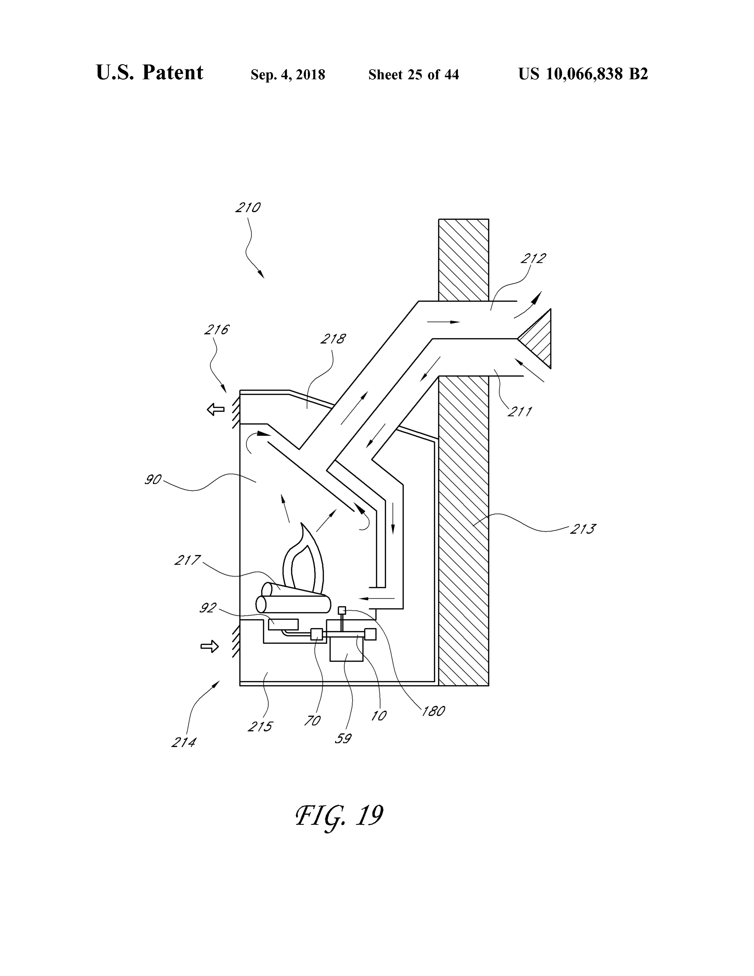
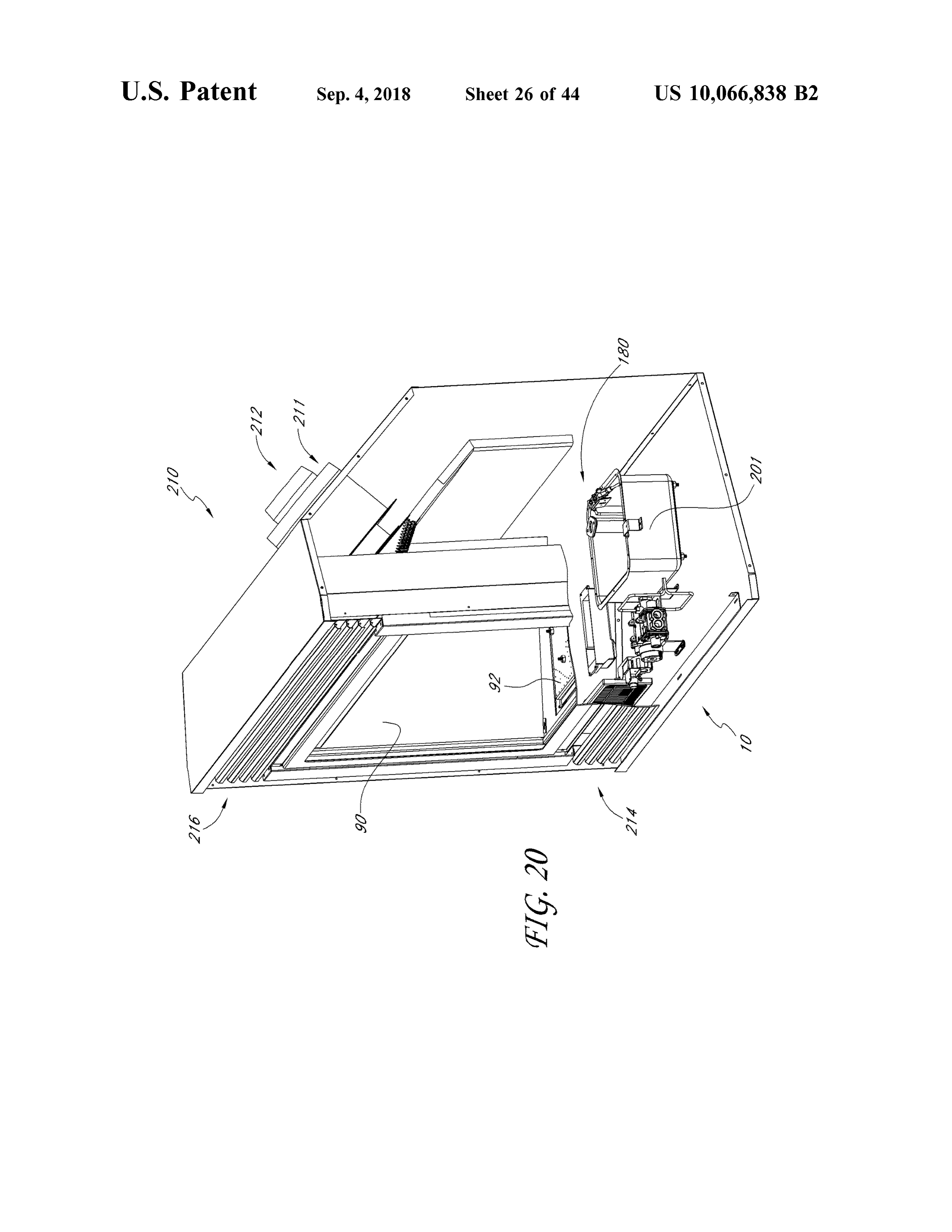
comprise a sealed combustion chamber , an air shutter con FIG . 20 shows a partial cross -section and disassemble trol and a fitting wherein the air shutter is within the view of a direct vent heater 210 .
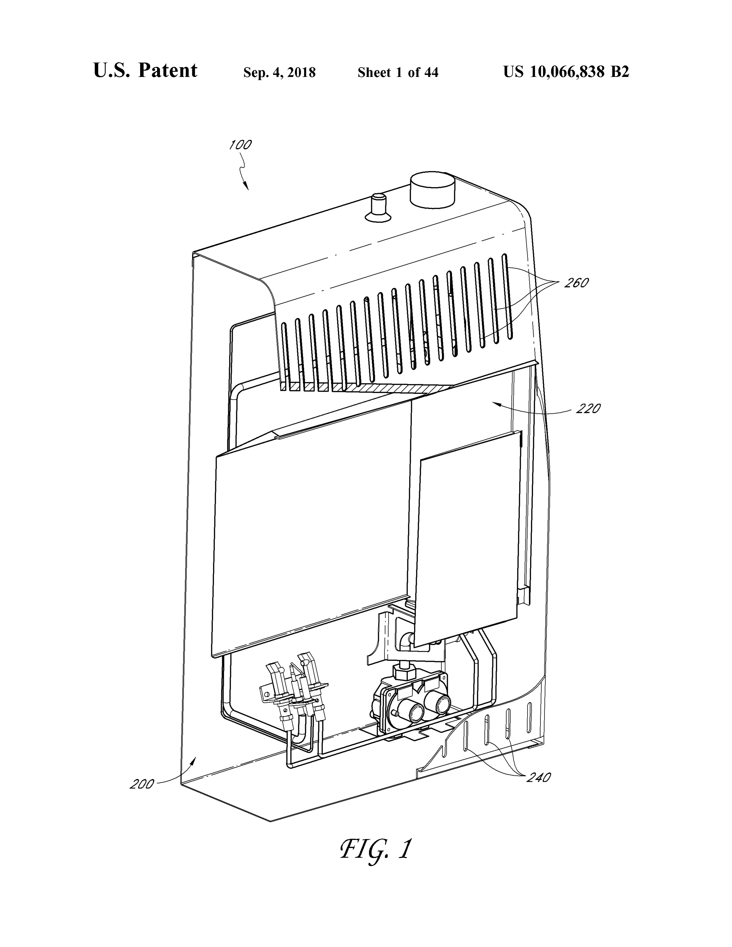
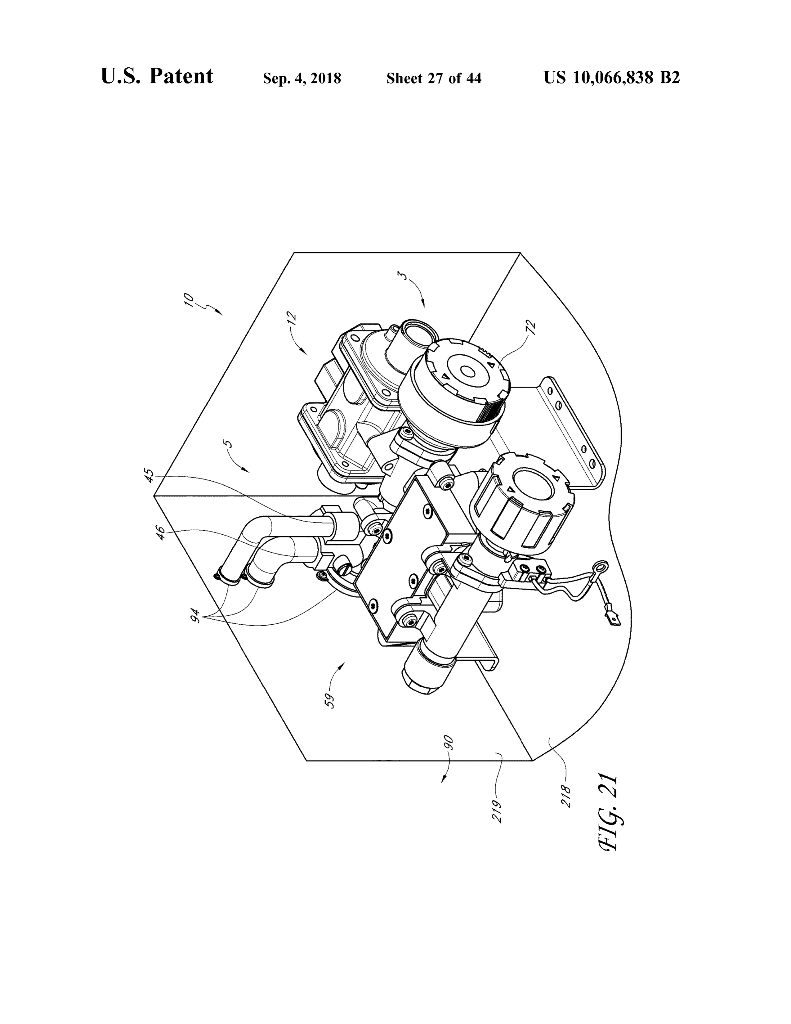
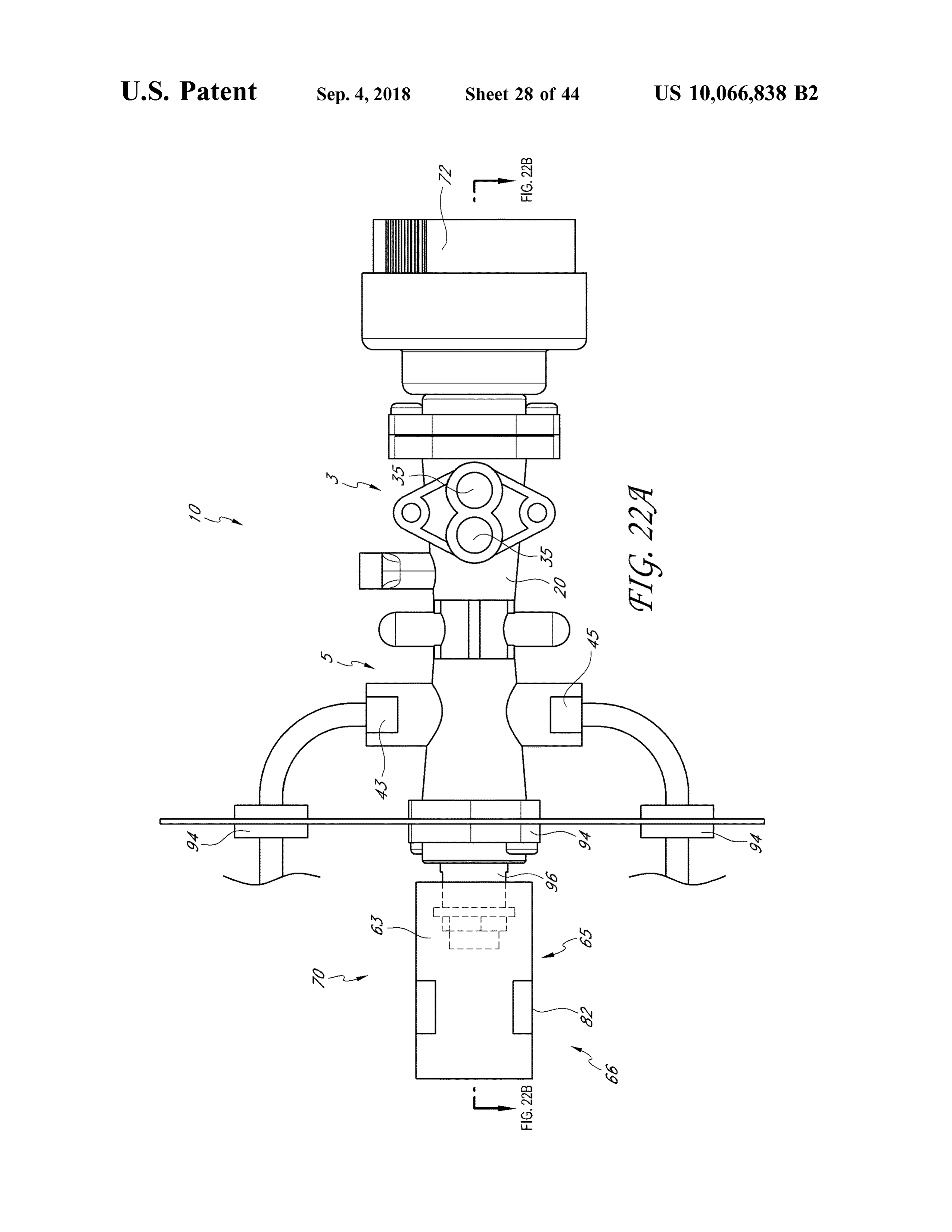
combustion chamber and surrounds the fuel line and the air FIG . 21 is a detail perspective view of part of a housing shutter control is outside the combustion chamber and the air of a dual fuel direct vent heater with a heating source . shutter control controls the air shutter through the same 5 FIG . 22A is side view of another embodiment of a heating fitting that the fuel line uses to pass into the sealed com - source .
bustion chamber. FIG . 22B is a cross - sectional view of the heating source of FIG . 22A in a first position .
BRIEF DESCRIPTION OF THE DRAWINGS FIG . 22C is a cross-sectional view of the heating source 10 of FIG . 22A in a second position .
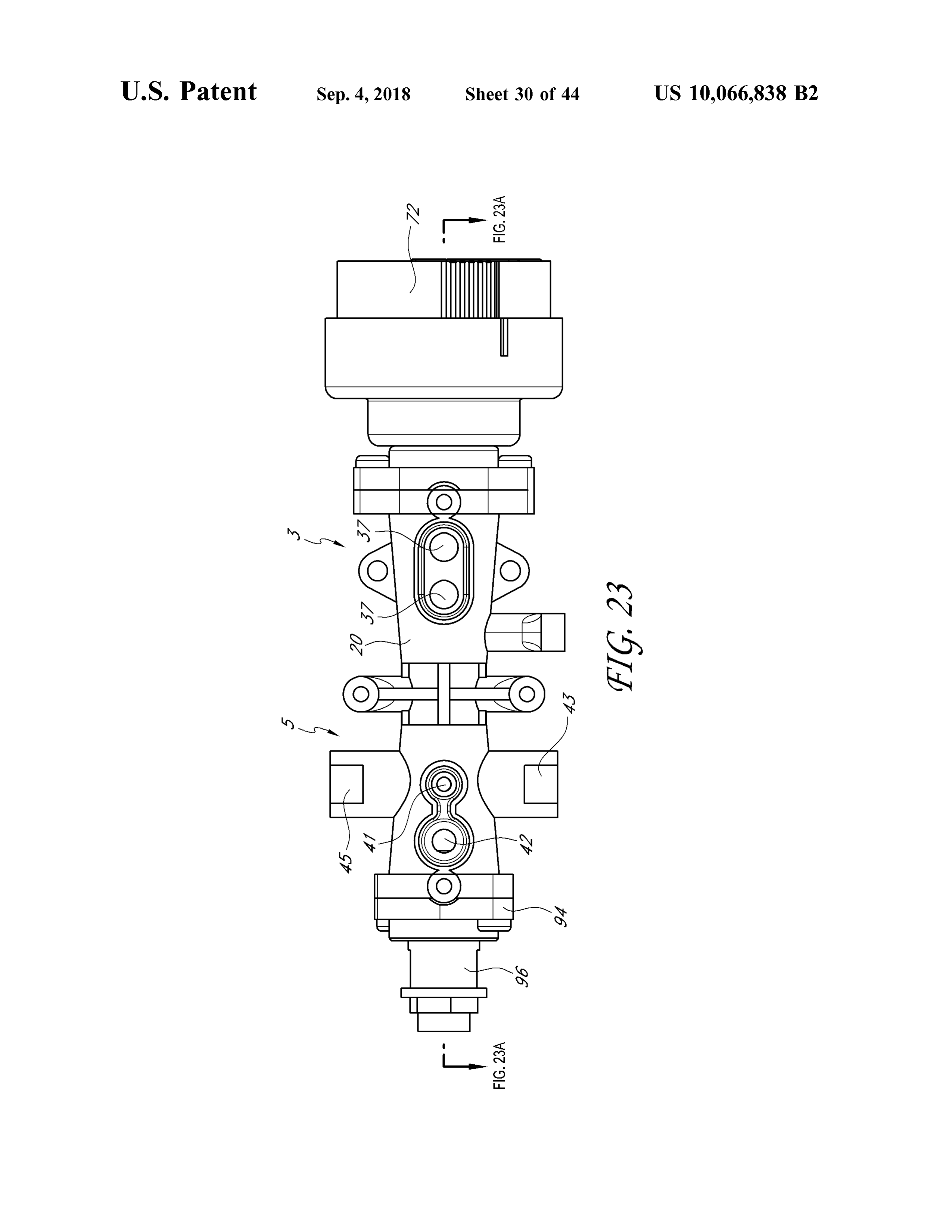
Various embodiments are depicted in the accompanying FIG . 23 is a side view of another embodiment of a heating drawings for illustrative purposes, and should in no way be source .
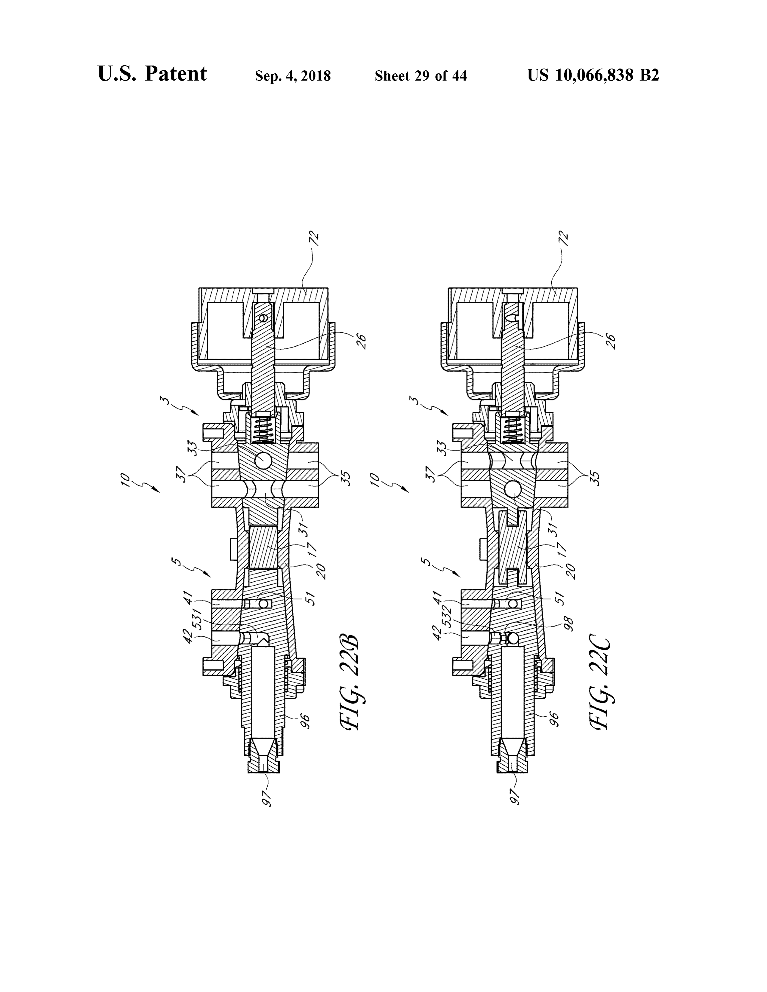
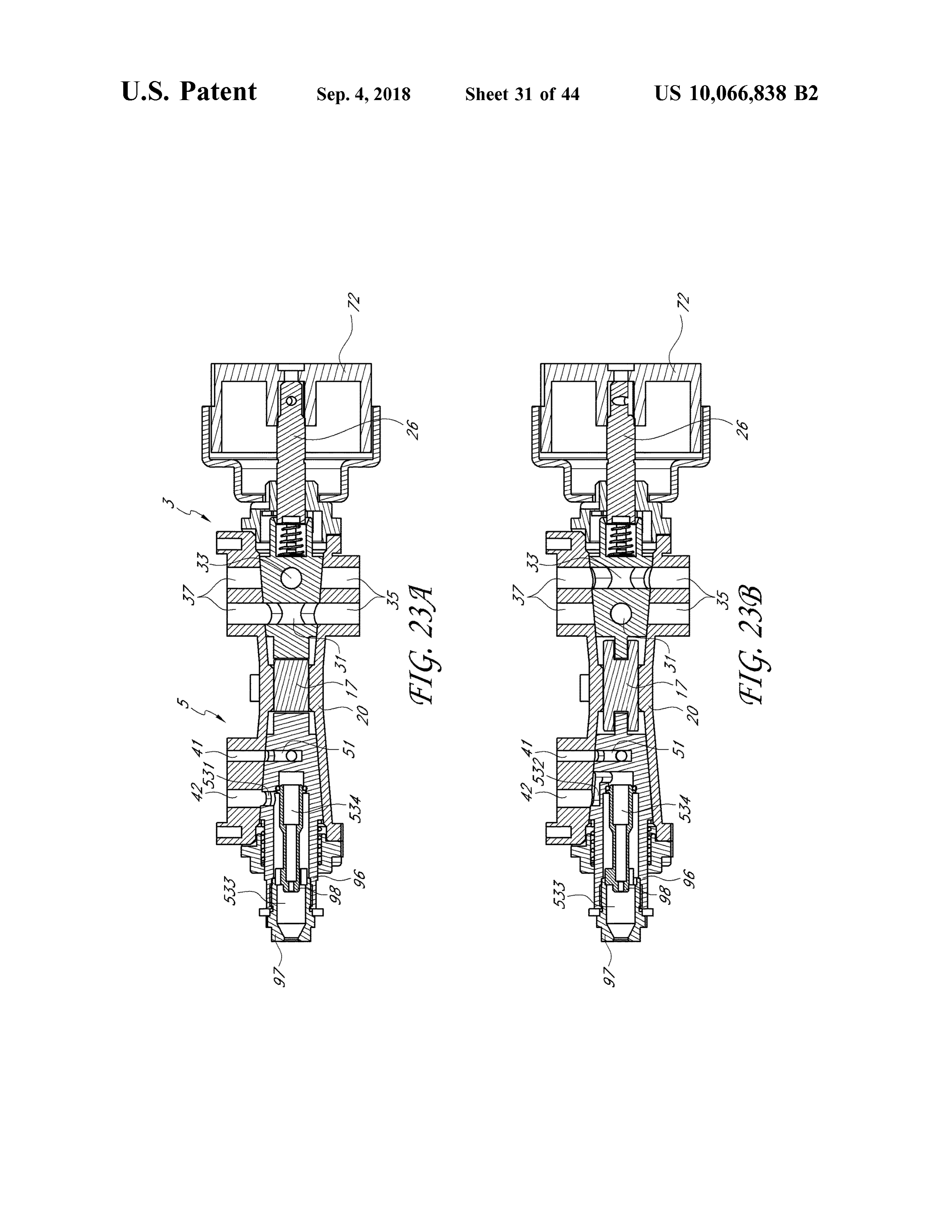
interpreted as limiting the scope of the inventions. FIG . 23A is a cross - sectional view is a cross -sectional FIG . 1 is a perspective cutaway view of a portion of one 15 viewFIG of. 23B the heating source of FIG . 23 in a first position .
embodiment of a heater configured to operate using either a of FIG . 23 in isa a second cross -sectional view of the heating source position .
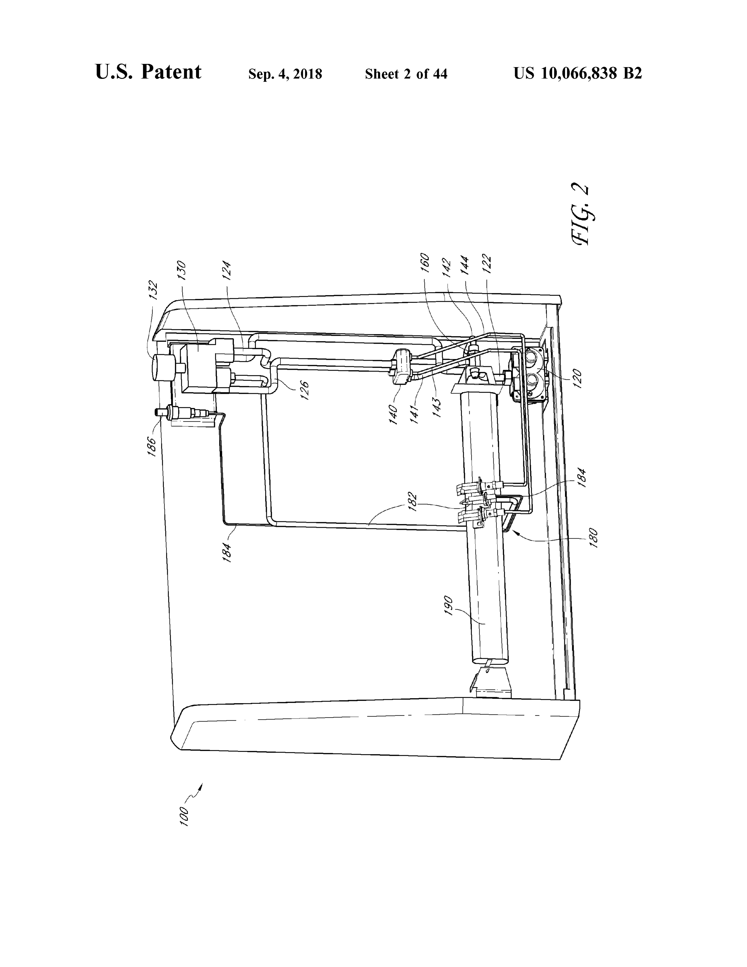
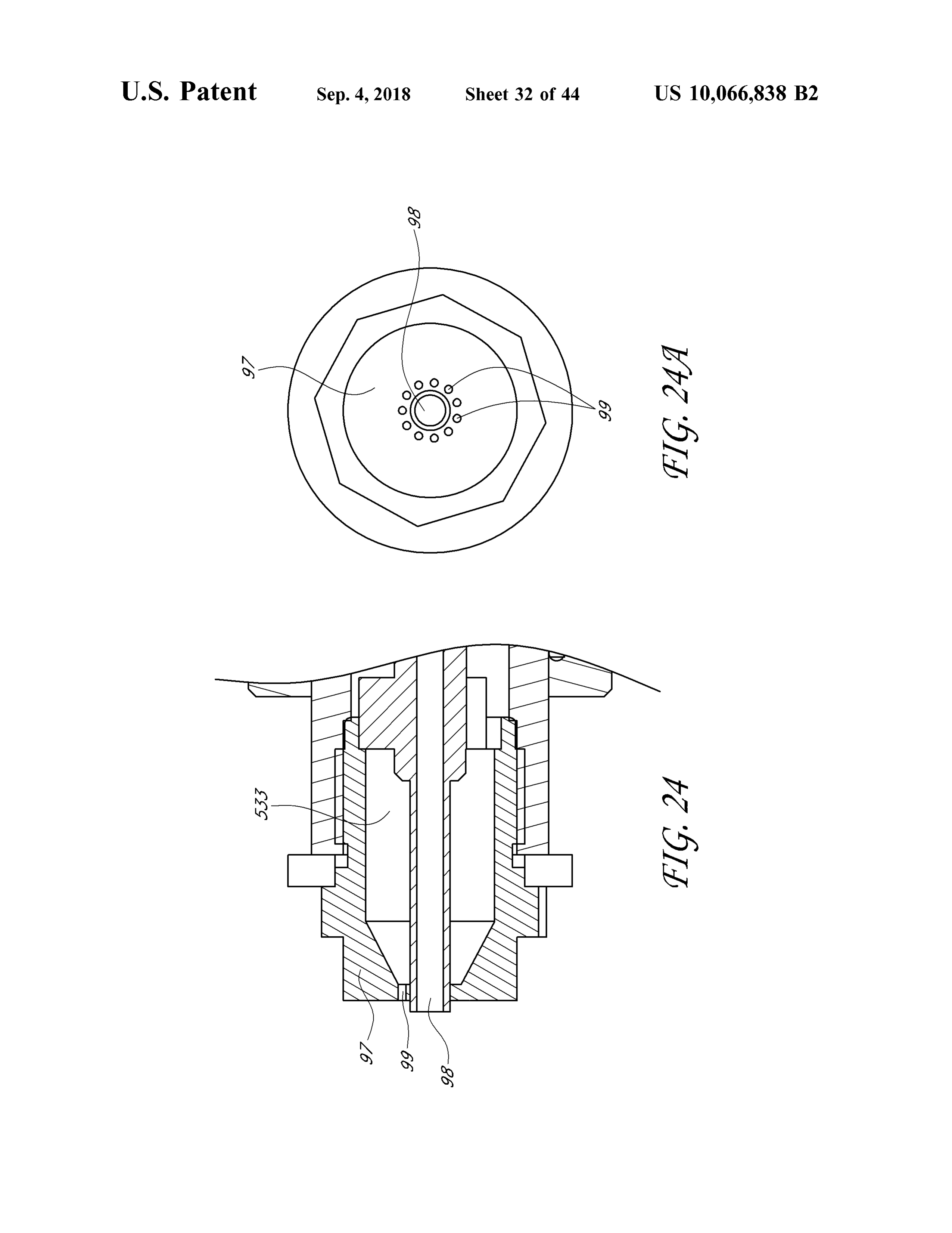
first fuel source or a second fuel source . FIG . 24 is a detail view of another embodiment of a FIG . 2 is a perspective cutaway view of the heater of FIG . nozzle from a heating source .
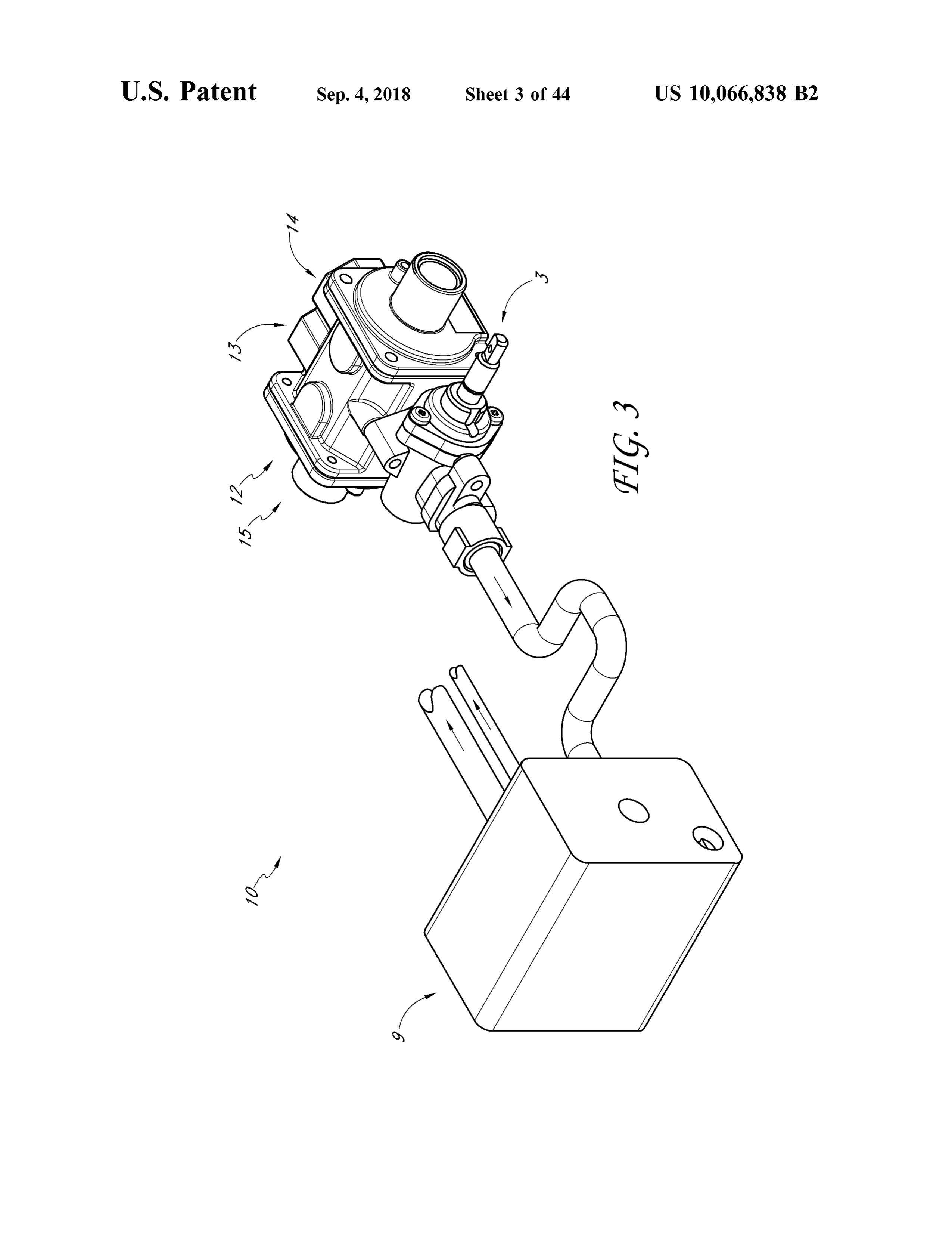
FIG . 3 is perspective view of one embodiment of a 20 . 24 FIG . 24A is a detail view of the end of the nozzle in FIG . heating source. FIG . 25A is a perspective view of parts of the heater FIG . 4 is a schematic view of a heating source wherein including a heating source and a basket that is part of a natural gas is selected . sealed combustion chamber .
FIG . 5 is a schematic view of a heating source wherein FIG . 25B shows a top view of the parts of the heater of liquid propane is selected . 25 FIG . 25A .
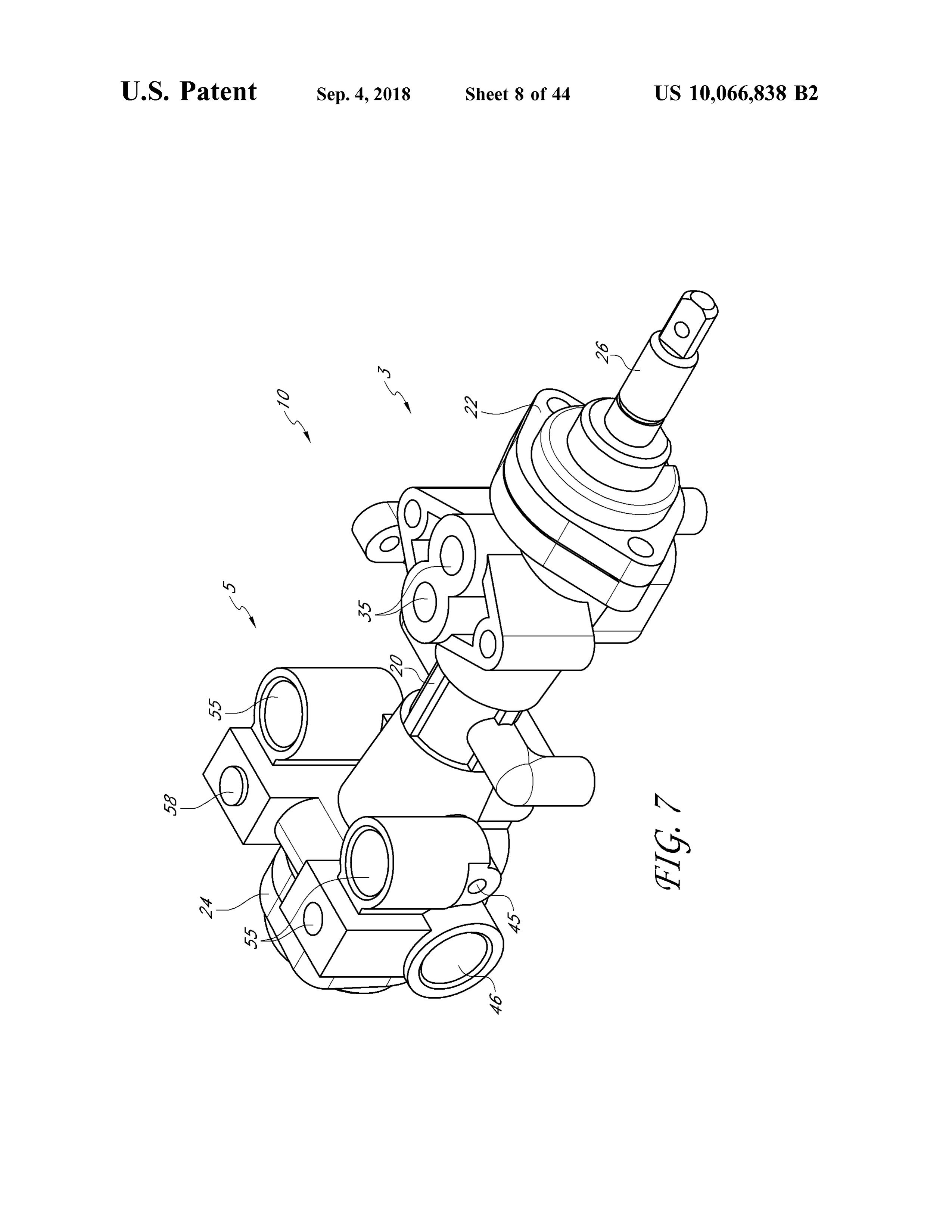
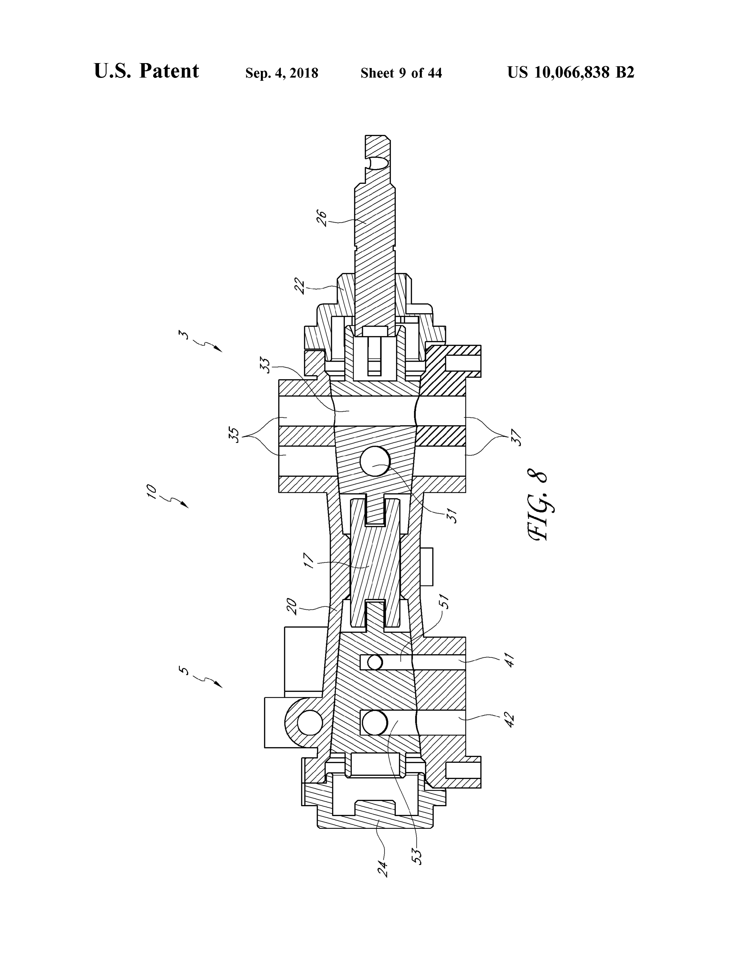
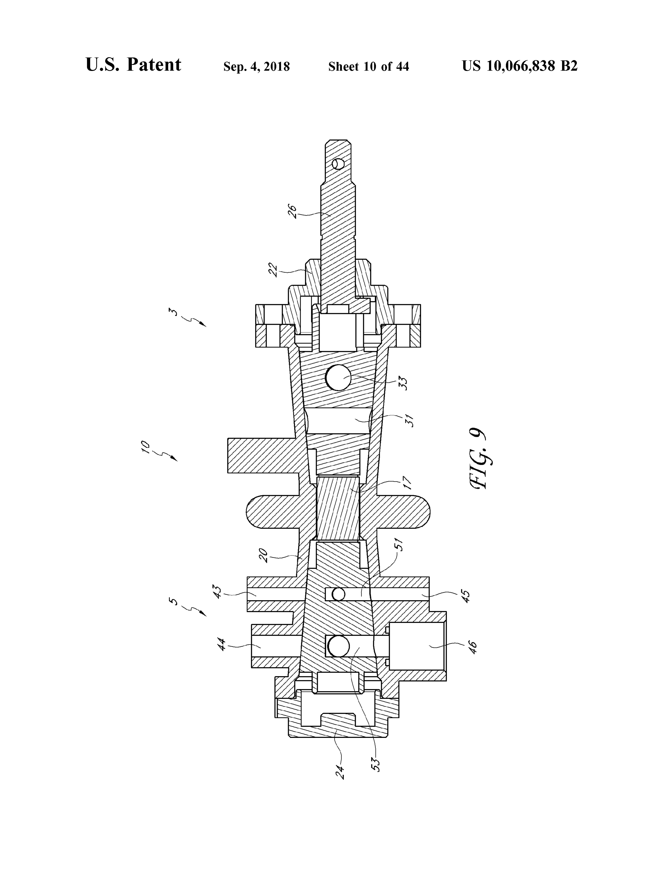
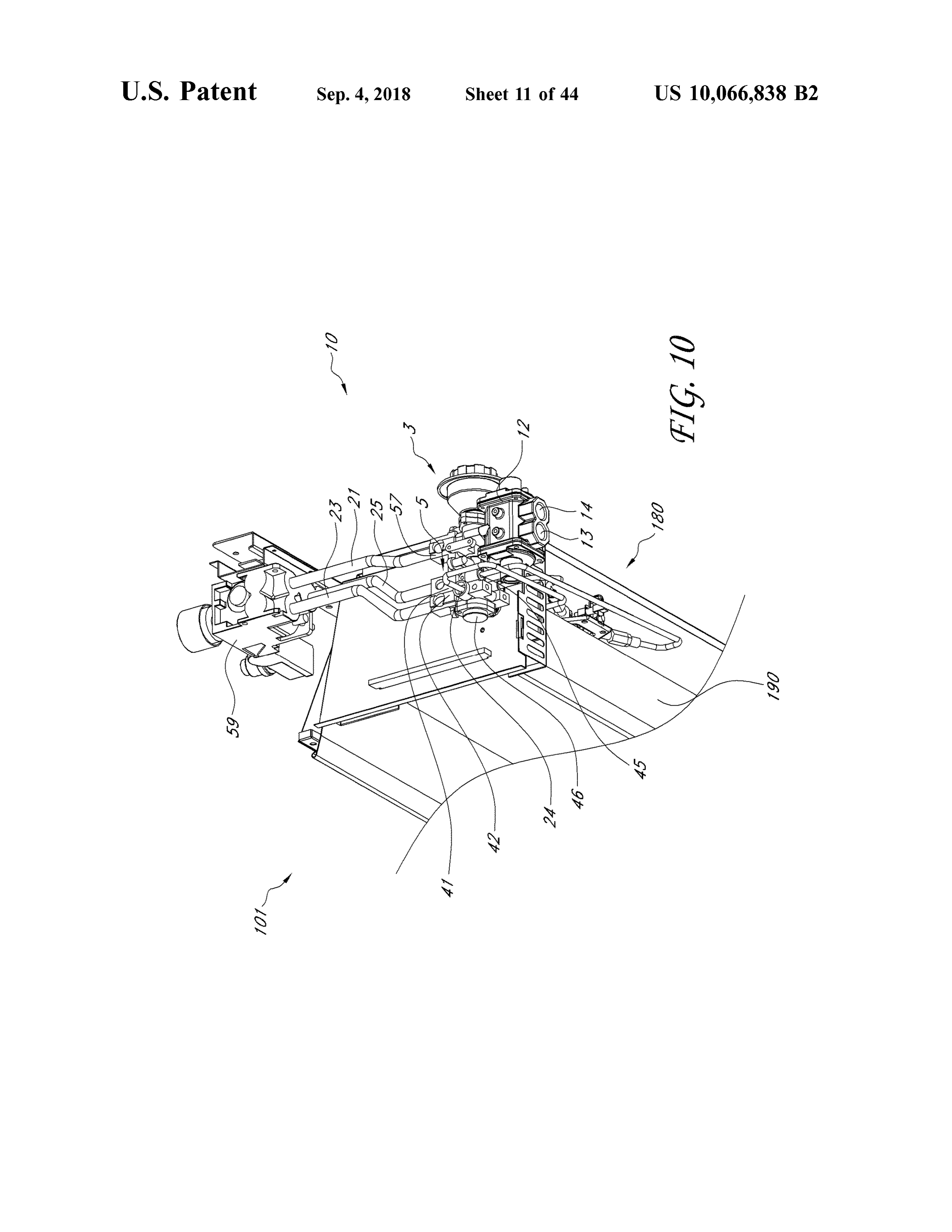
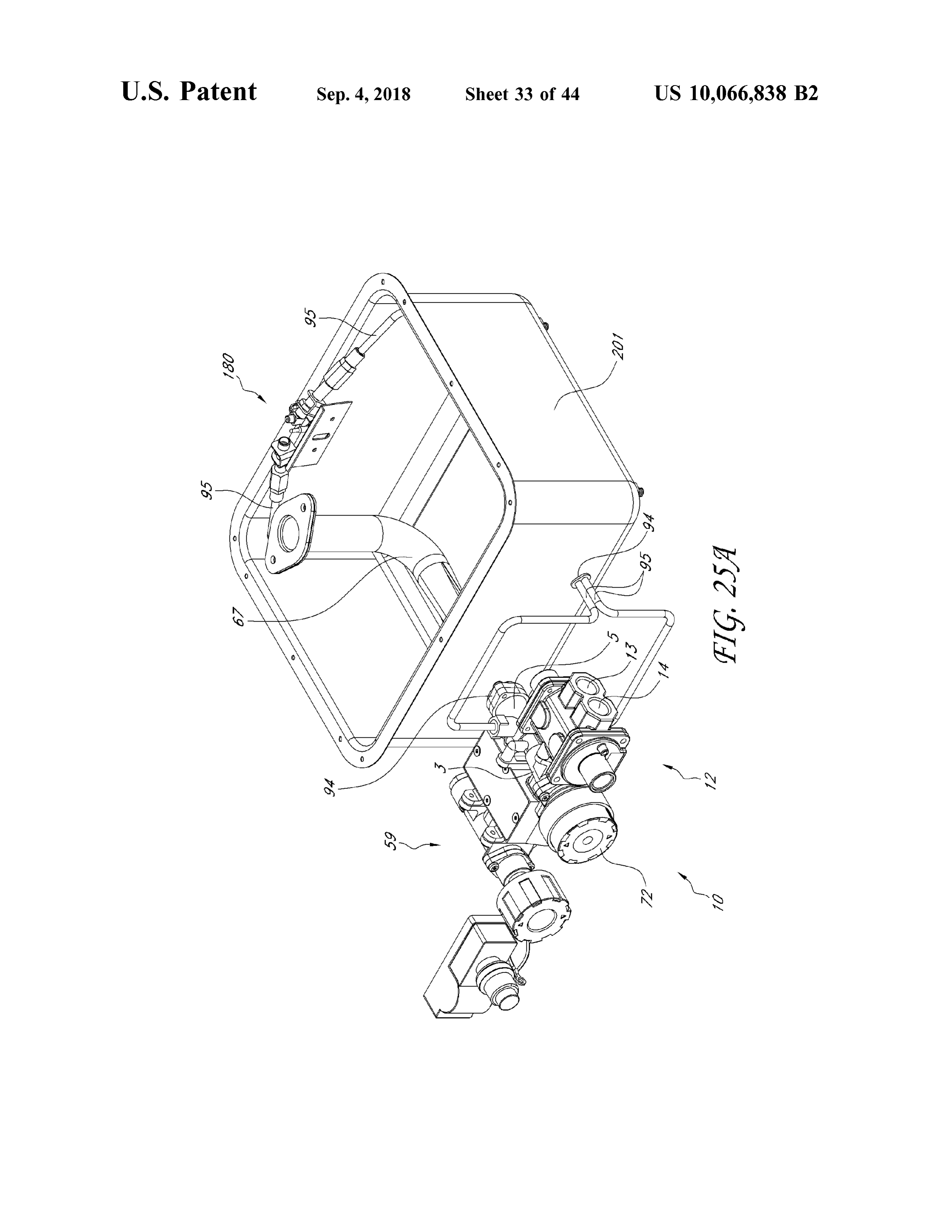
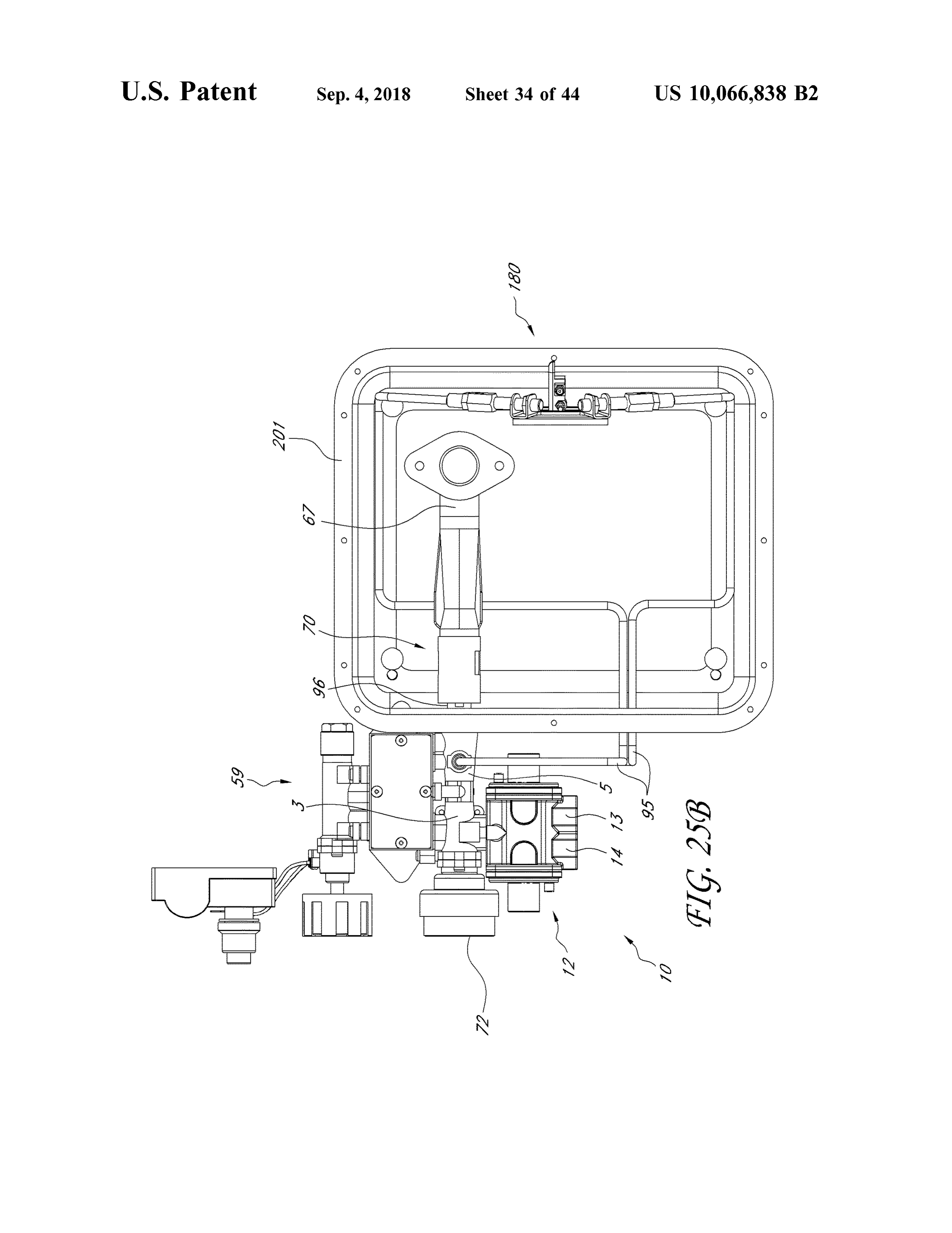
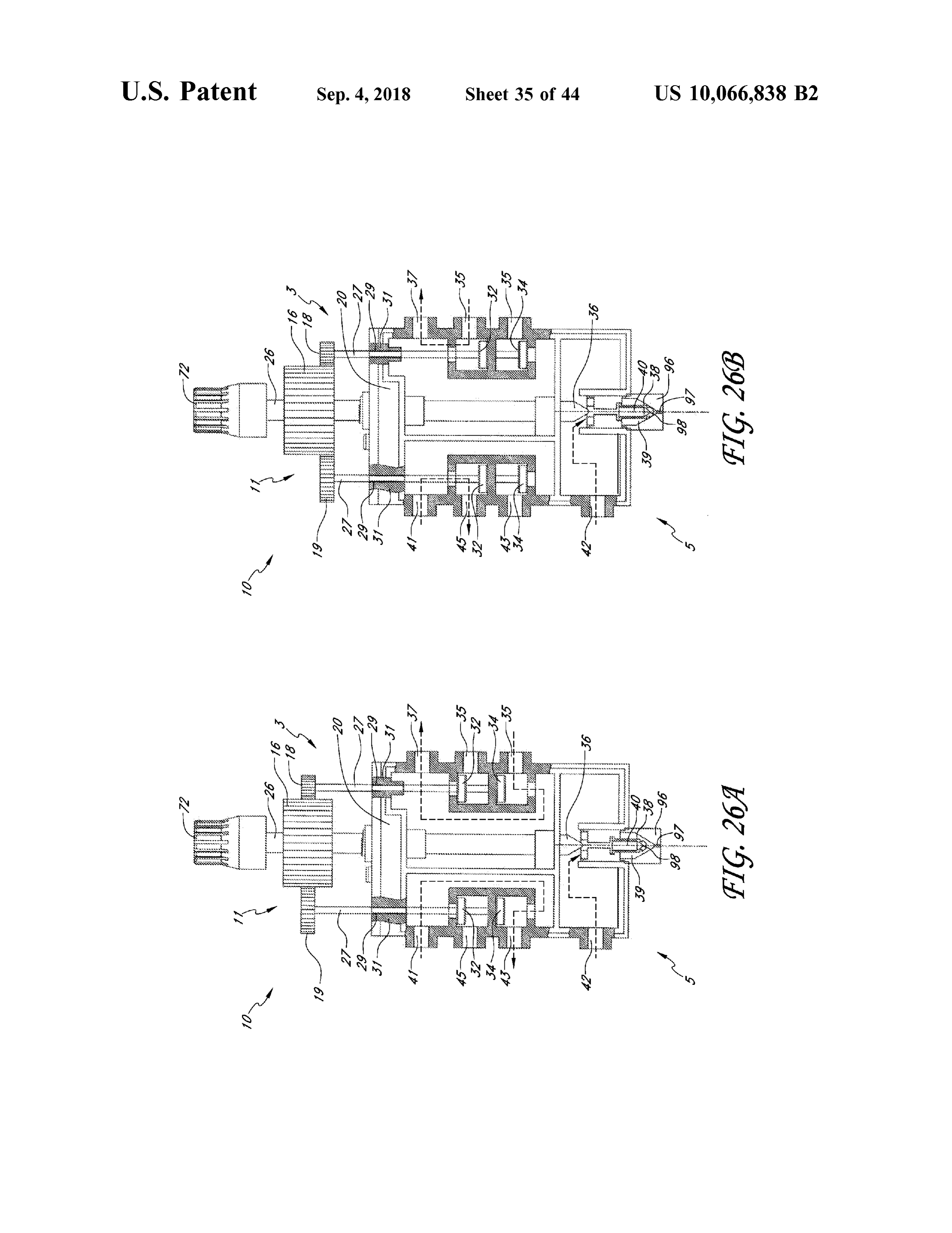
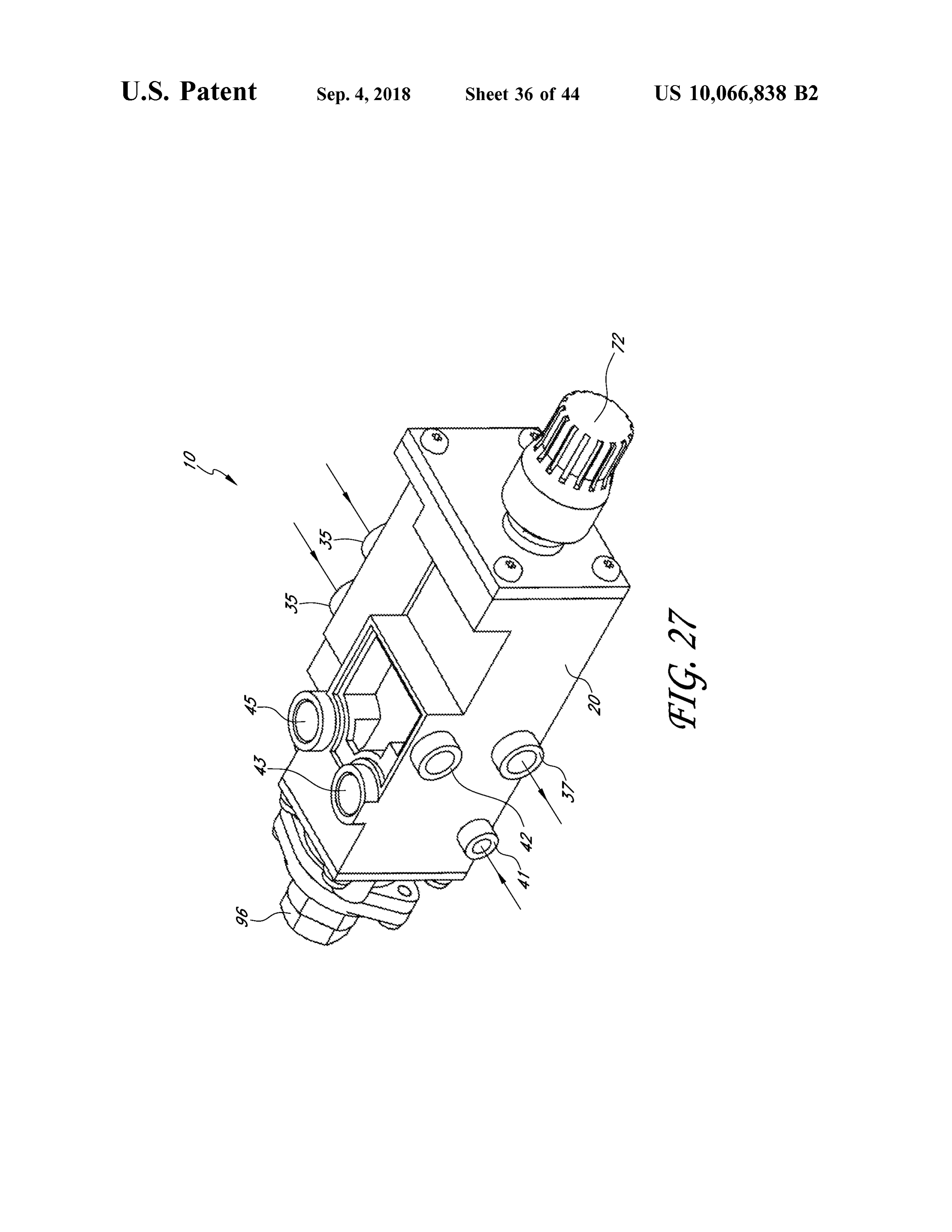
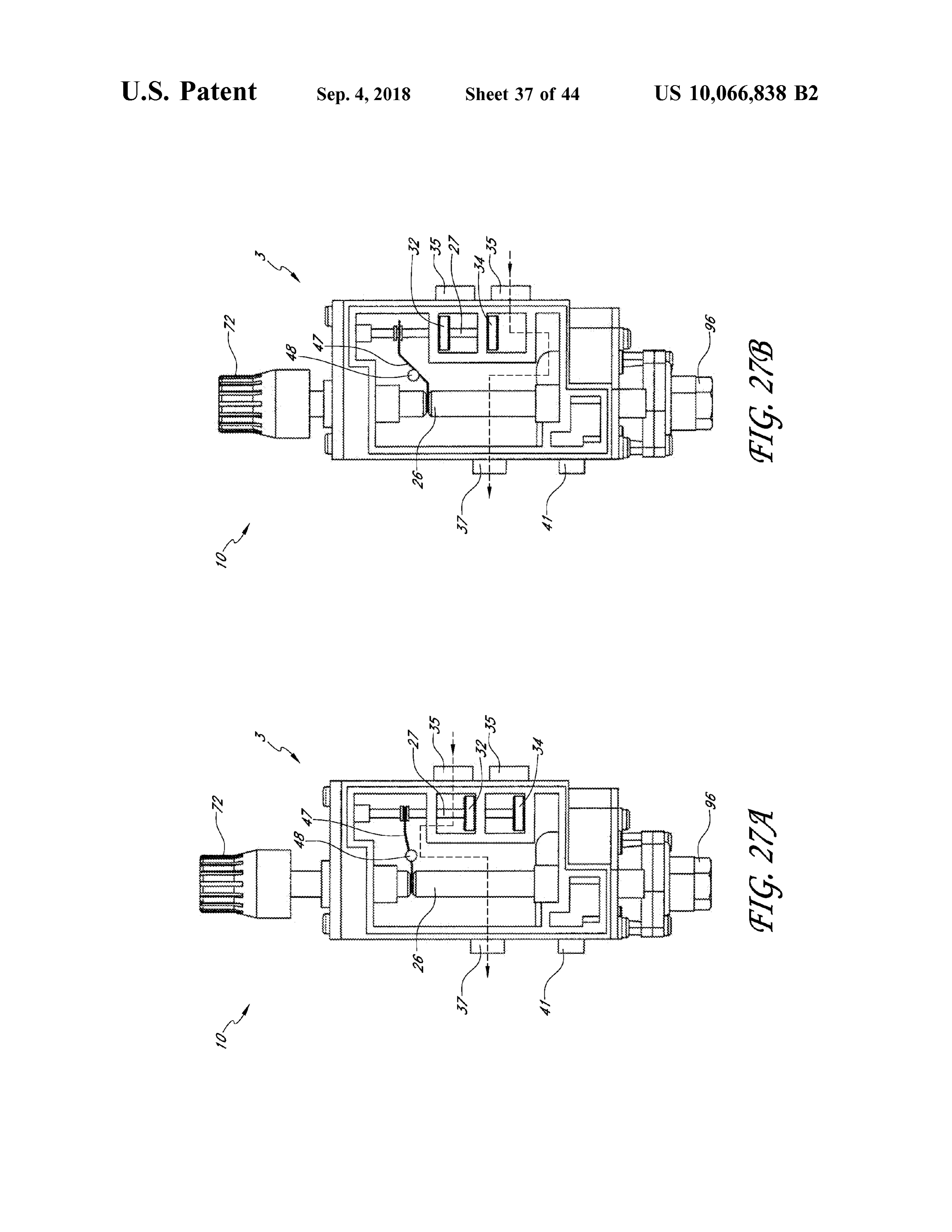
FIG . 6 is a schematic view of a heating source having a FIGS. 26A and B are schematic and partial cross - sectional fuel selector valve and an outlet valve wherein natural gas is views of another embodiment of a heating source in a first selected . and second configuration , respectively . FIG . 6A is a diagram illustrating certain functions. FIG . 27 shows another embodiment of a heating source . FIG . 7 is a side and top perspective view of another 30 FIGS. 27A and B are schematic and partial cross -sectional embodiment of a heating source . views of the heating source of FIG . 27 in a first and second FIG . 8 is a cross-sectional view from the top of the heating configuration , respectively.
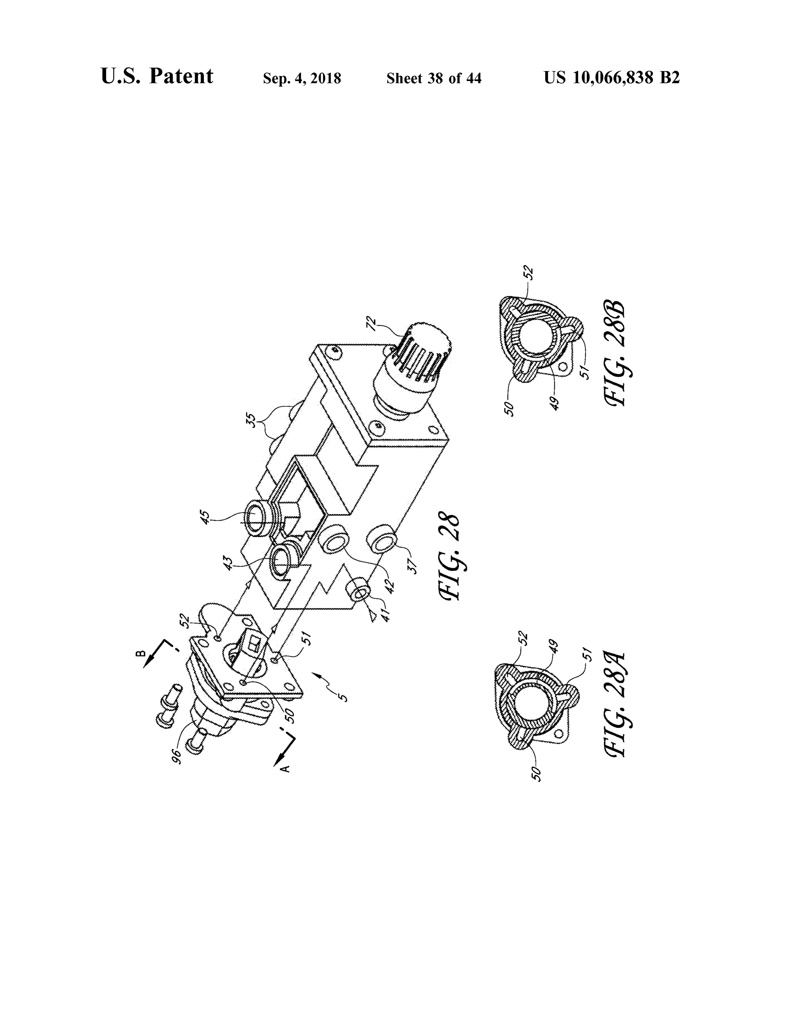
source of FIG . 7 . FIG . 28 is a partially dissembled view of the heating FIG . 9 is a cross -sectional view from the side of the source of FIG . 27.
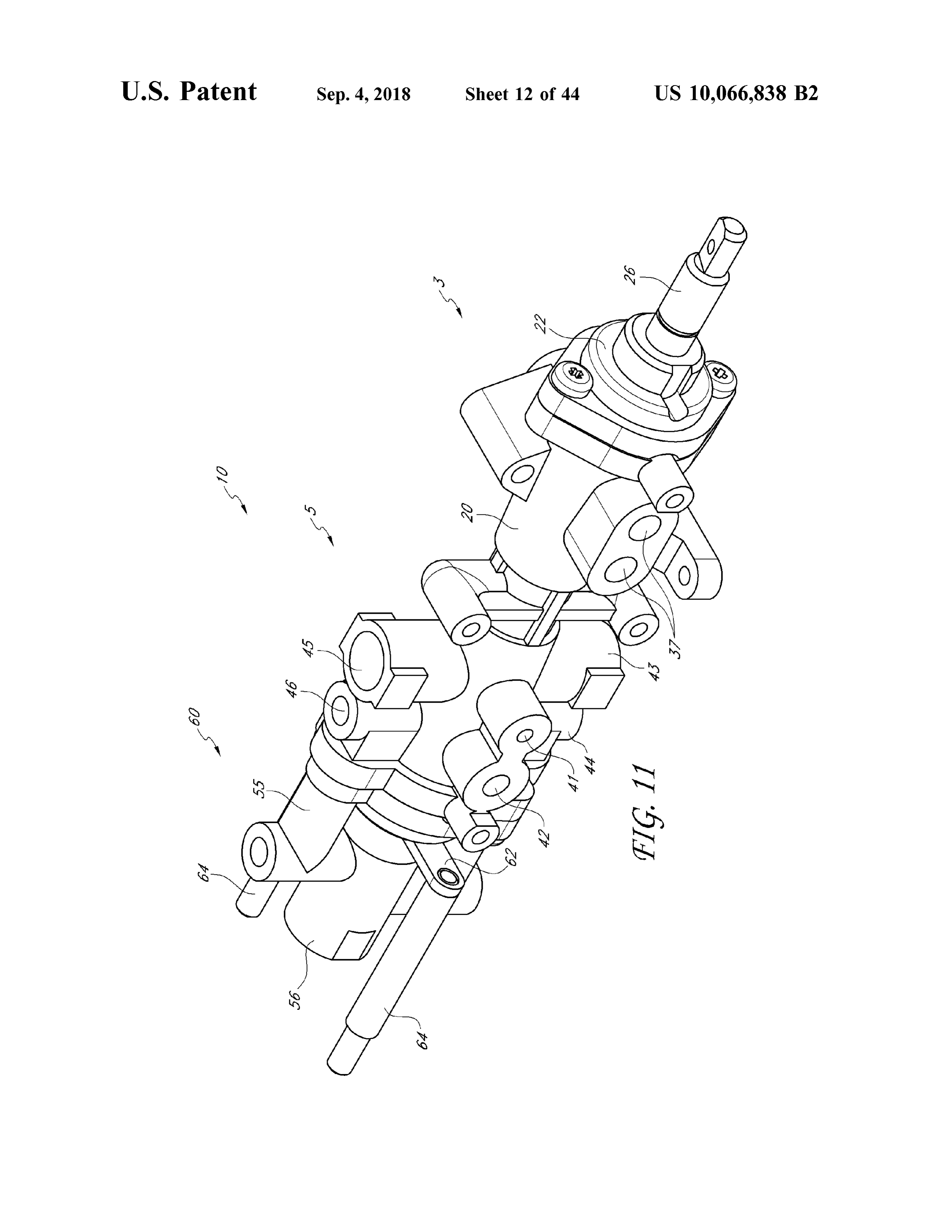
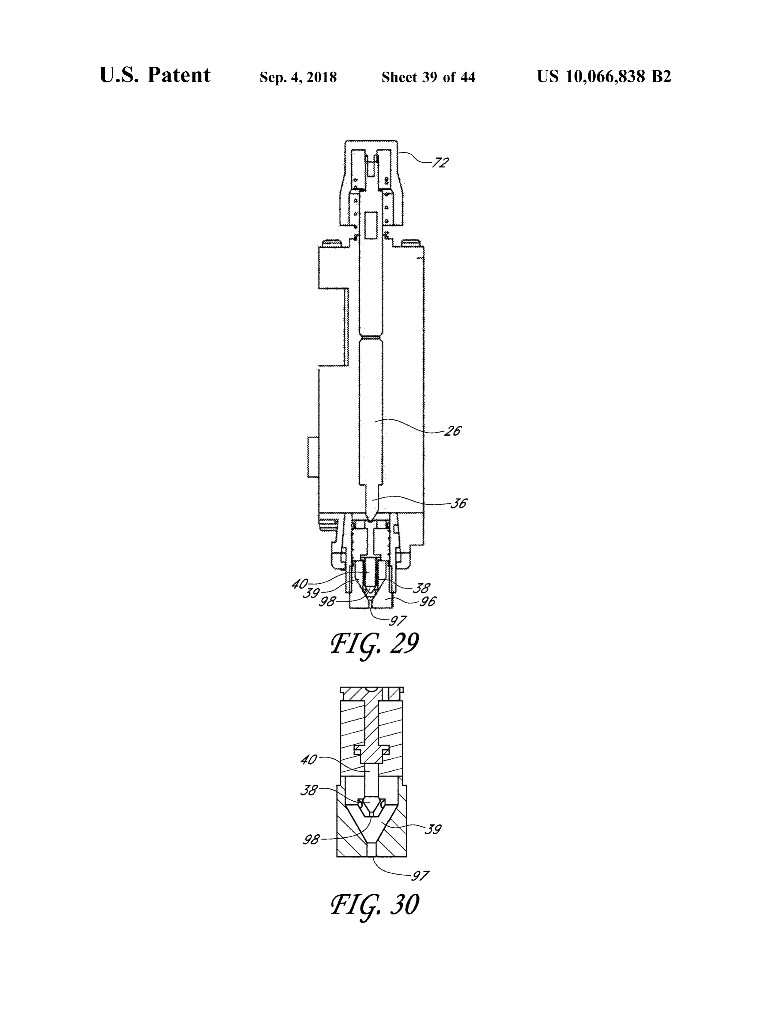
heating source of FIG . 7 . 35 FIGS. 28A and B are cross -sectional views of a portion of FIG . 10 is a perspective view of another embodiment of the heating source of FIG . 28 taken along line A - B and a heating source. showing a first and second configuration , respectively . FIG . 11 is another embodiment of a heating source . FIG . 29 is a schematic cross -sectional view of the heating FIG . 12A is a perspective view of an air shutter coupled source of FIG . 27 .
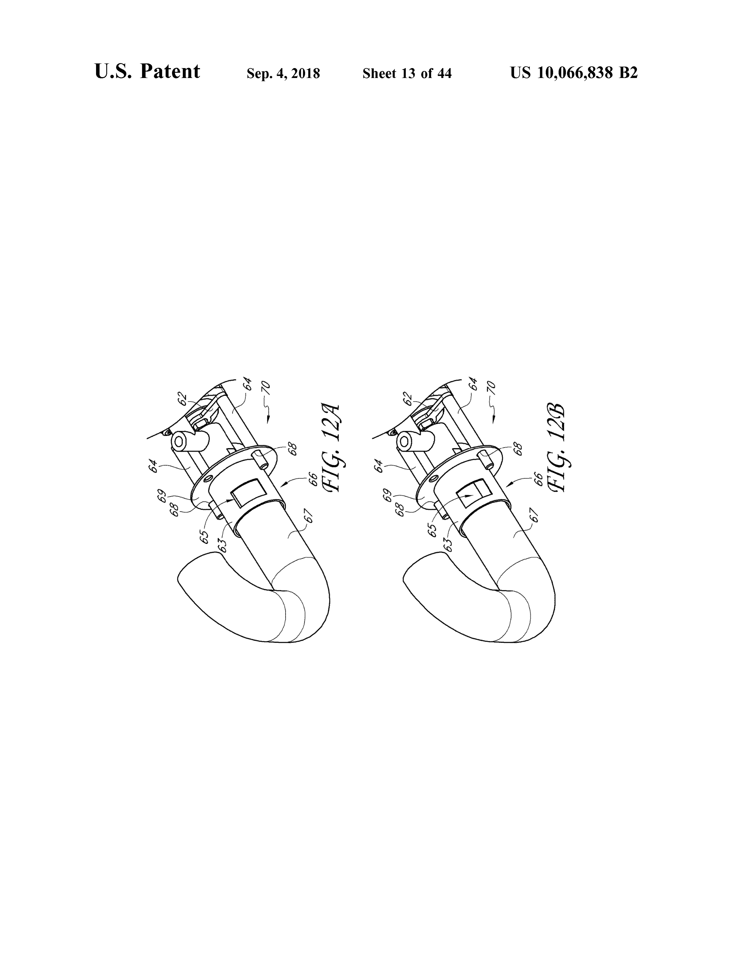
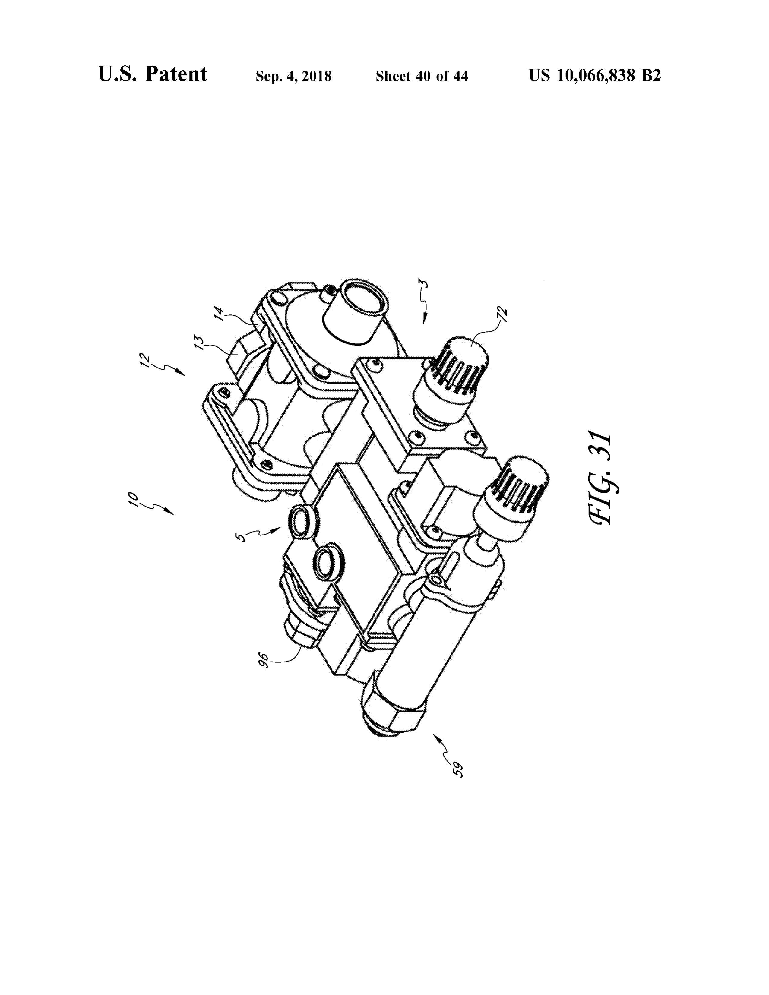
with a fuel delivery line in a first operational configuration . 40 FIG . 30 illustrates partial cross-section of a portion of the FIG . 12B is a perspective view of an air shutter coupled heating source of FIG . 27 including a nozzle . with a fuel delivery line in a second operational configura - FIG . 31 shows a perspective view of another embodiment tion . of a heating source .
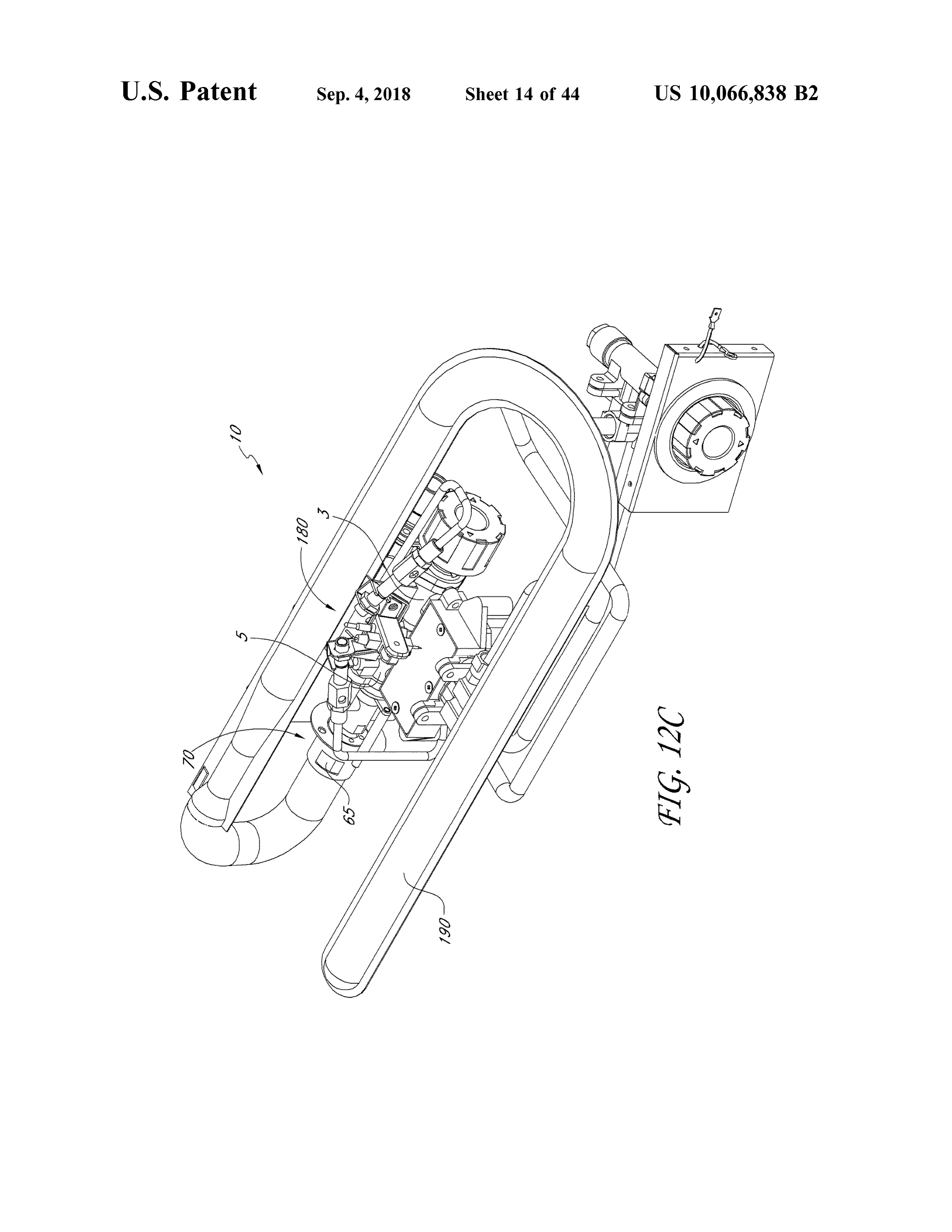
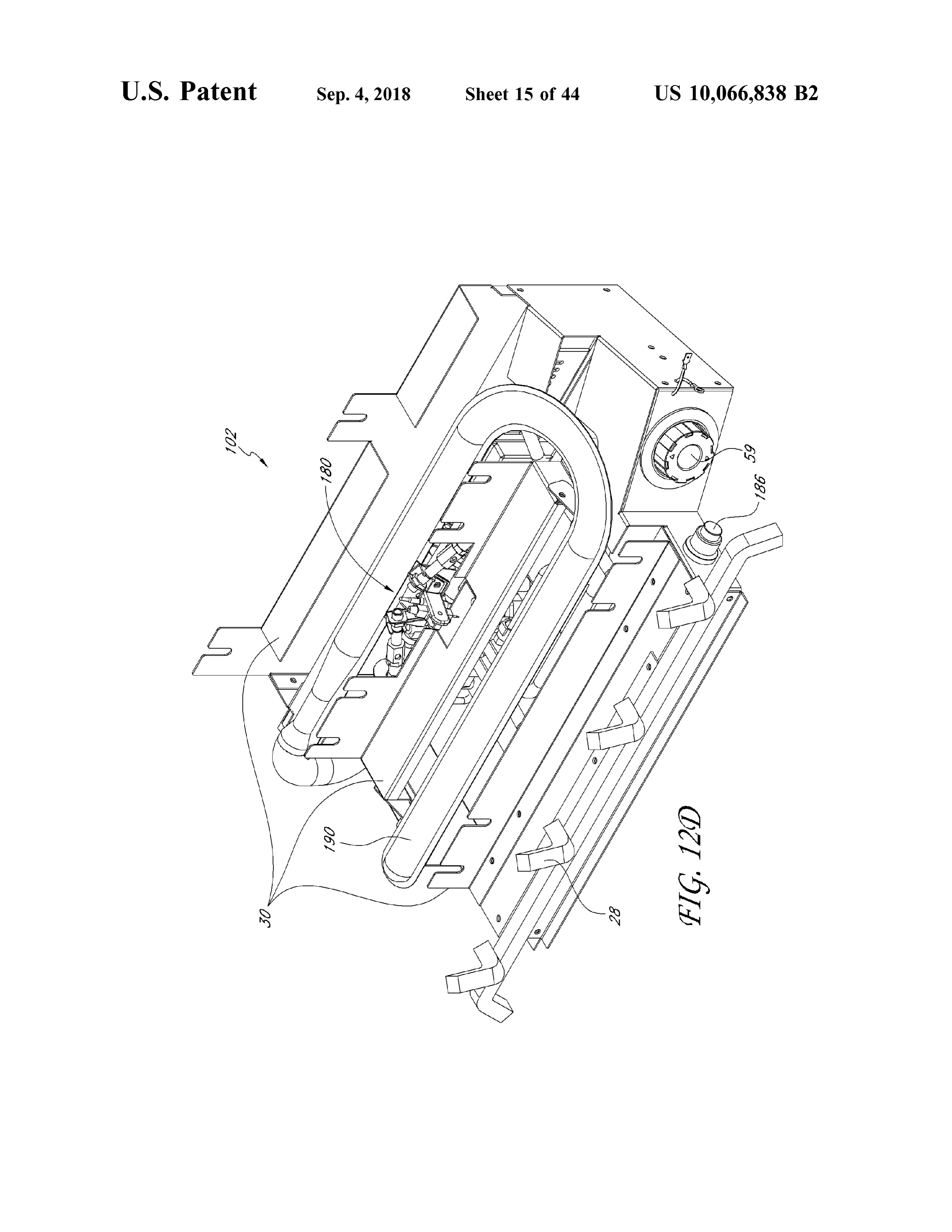
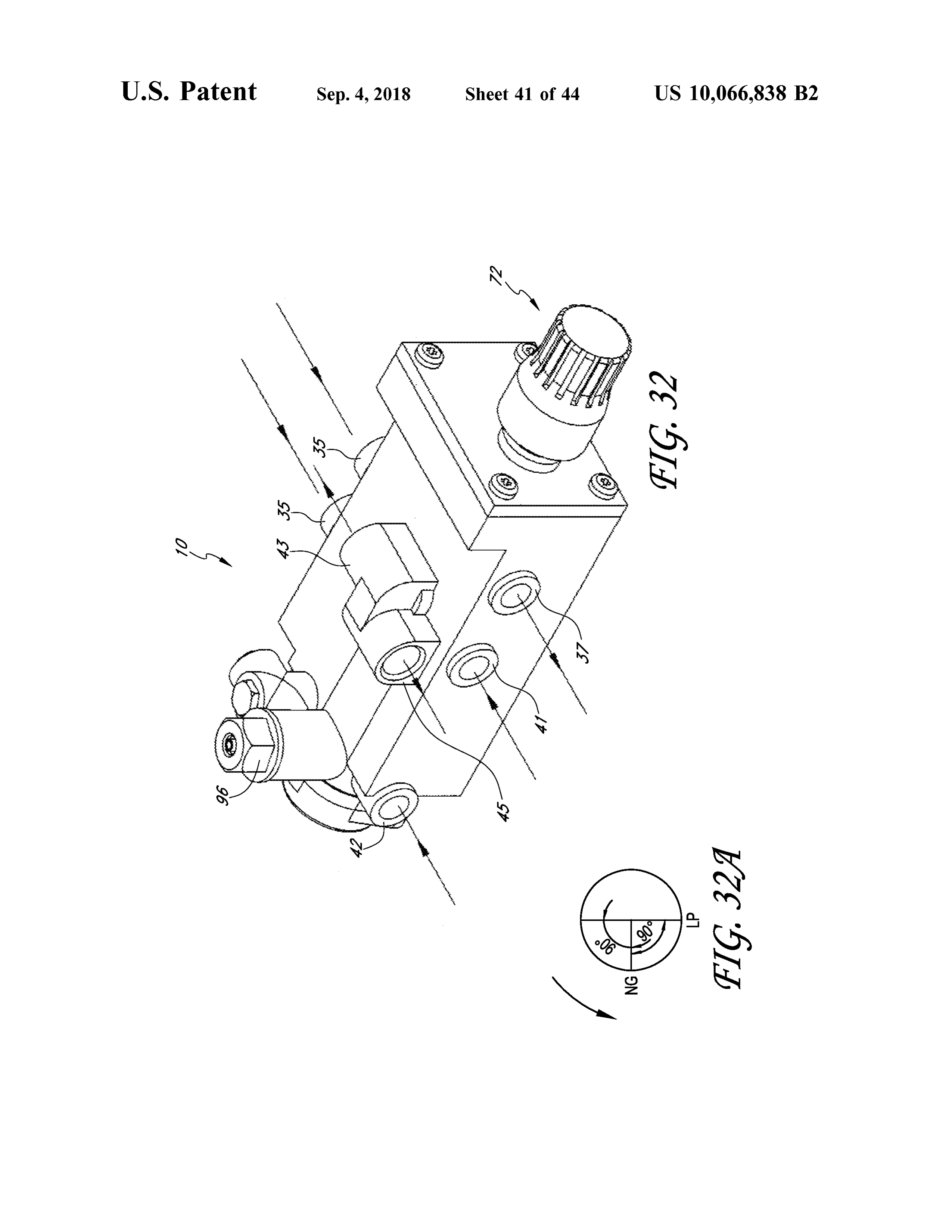
FIG . 12C is a partially dissembled view of a gas log insert. FIG . 32 shows a perspective view of another embodiment FIG . 12D is a gas log insert that can be used in a 45 of a heating source .
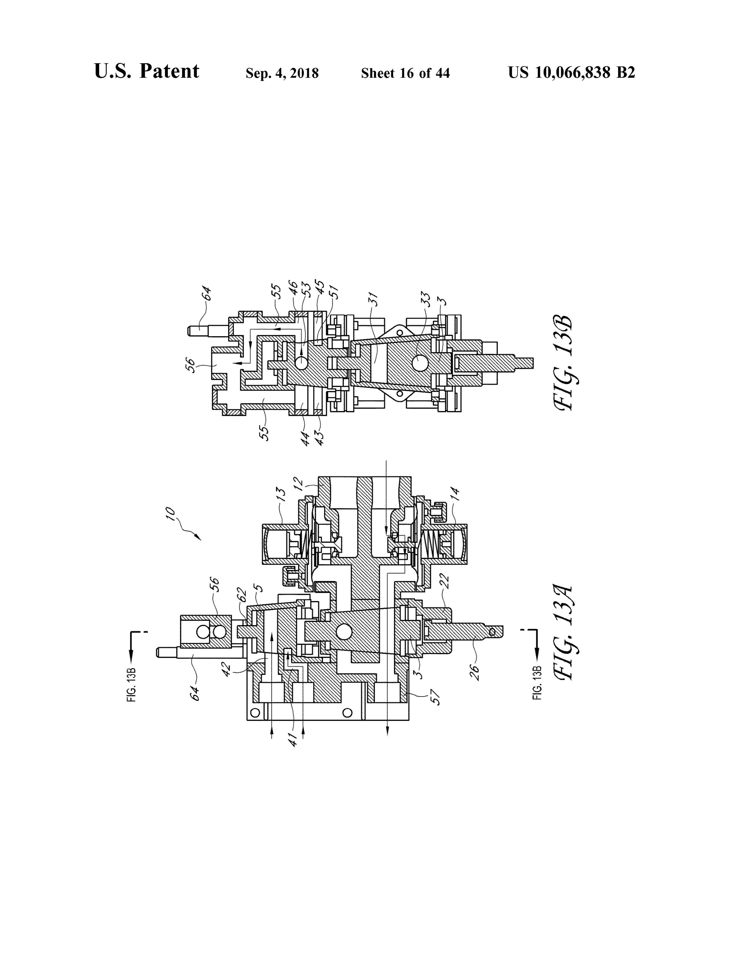
preexisting fireplace. FIG . 32A schematically illustrates the positions of an FIGS. 13A - B are top and a side cross -sectional views, internal shaft of the heating source of FIG . 32 . respectively , of another embodiment of a heating source in a first position .
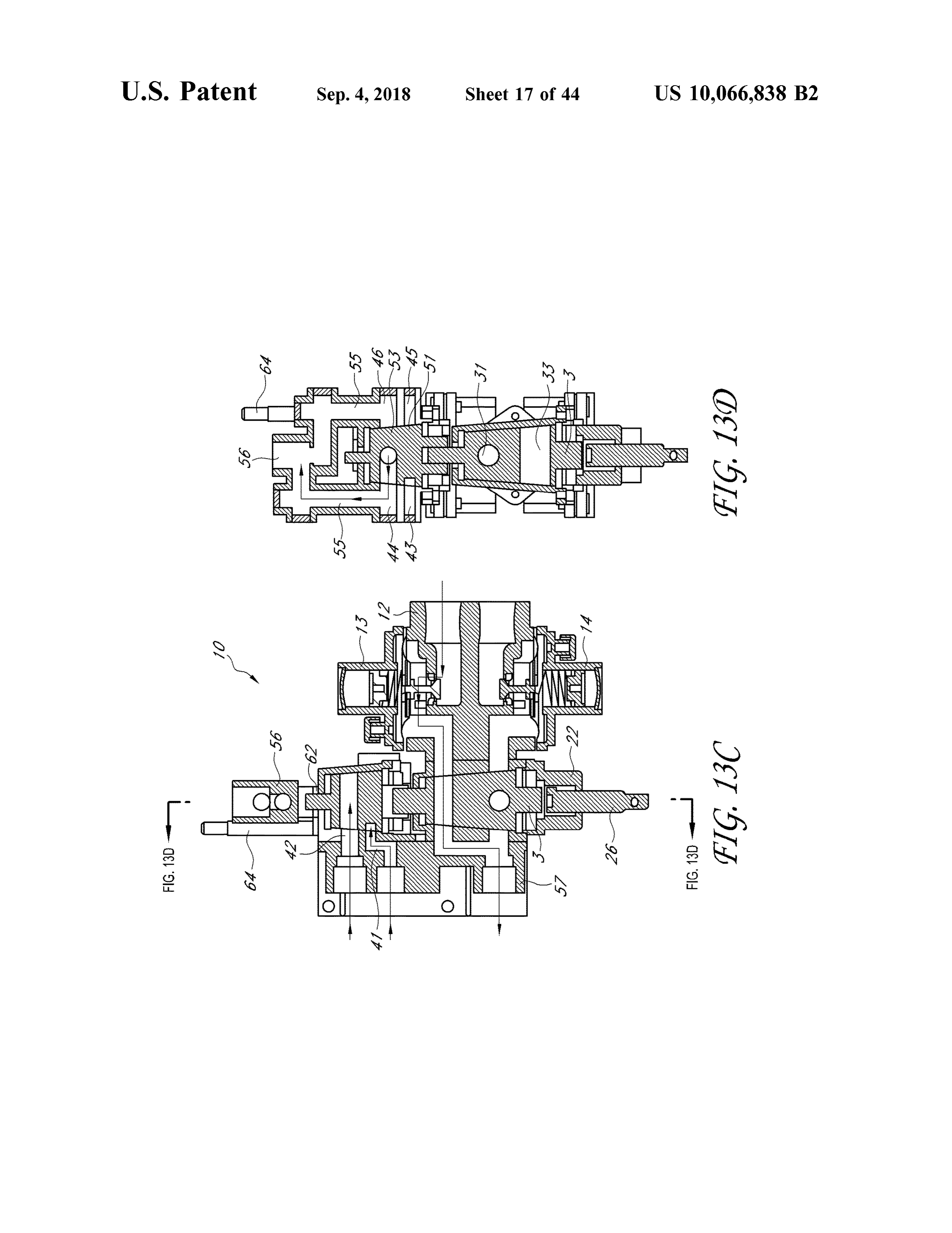
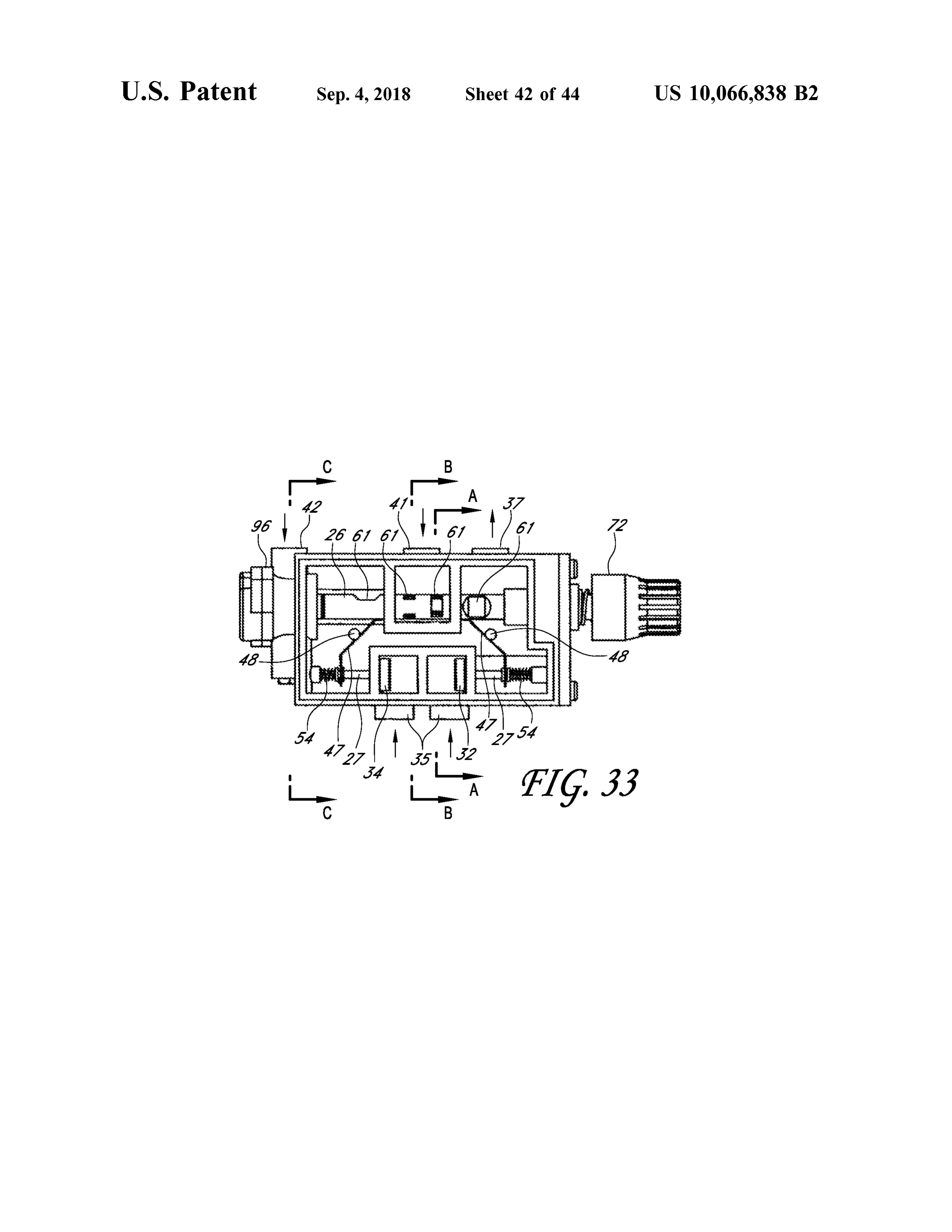
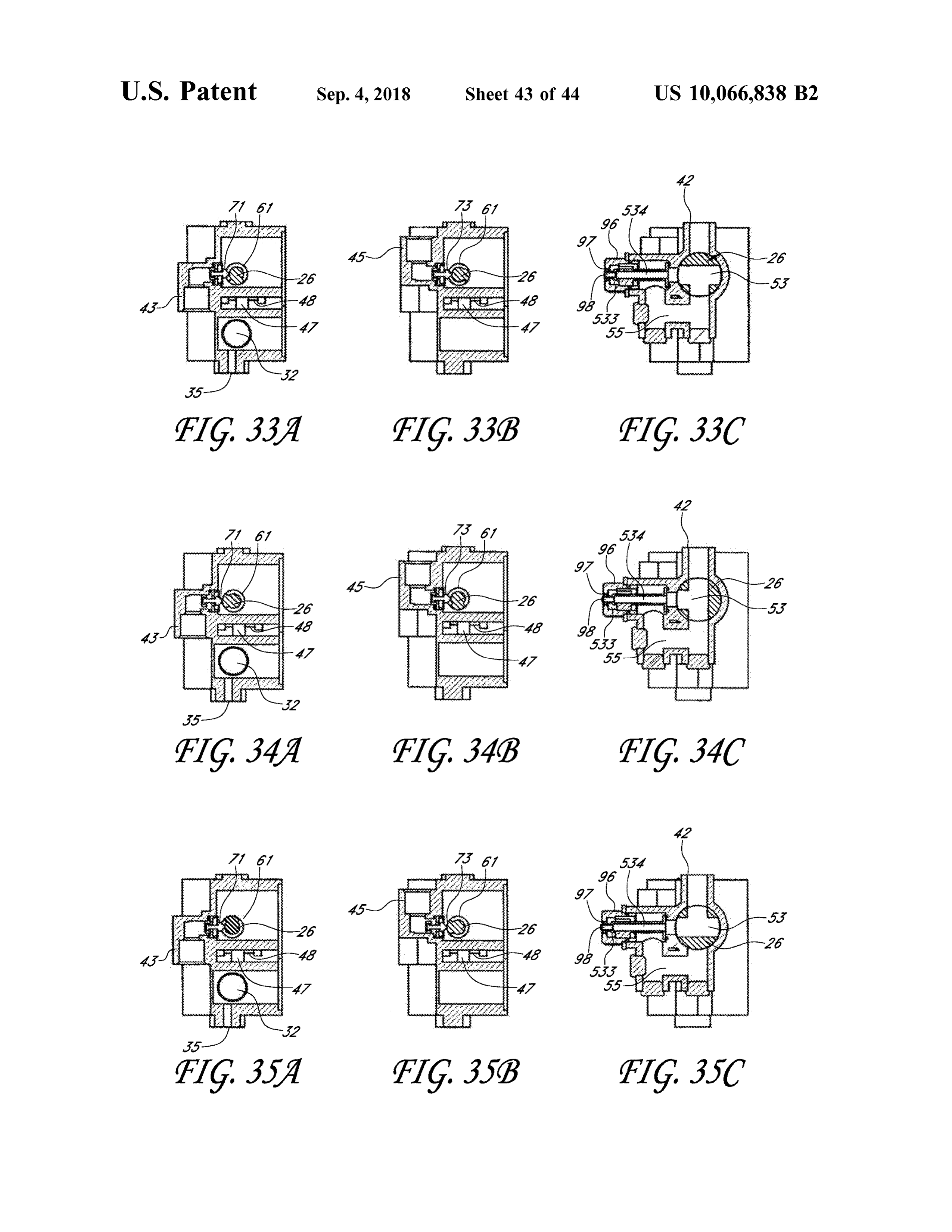
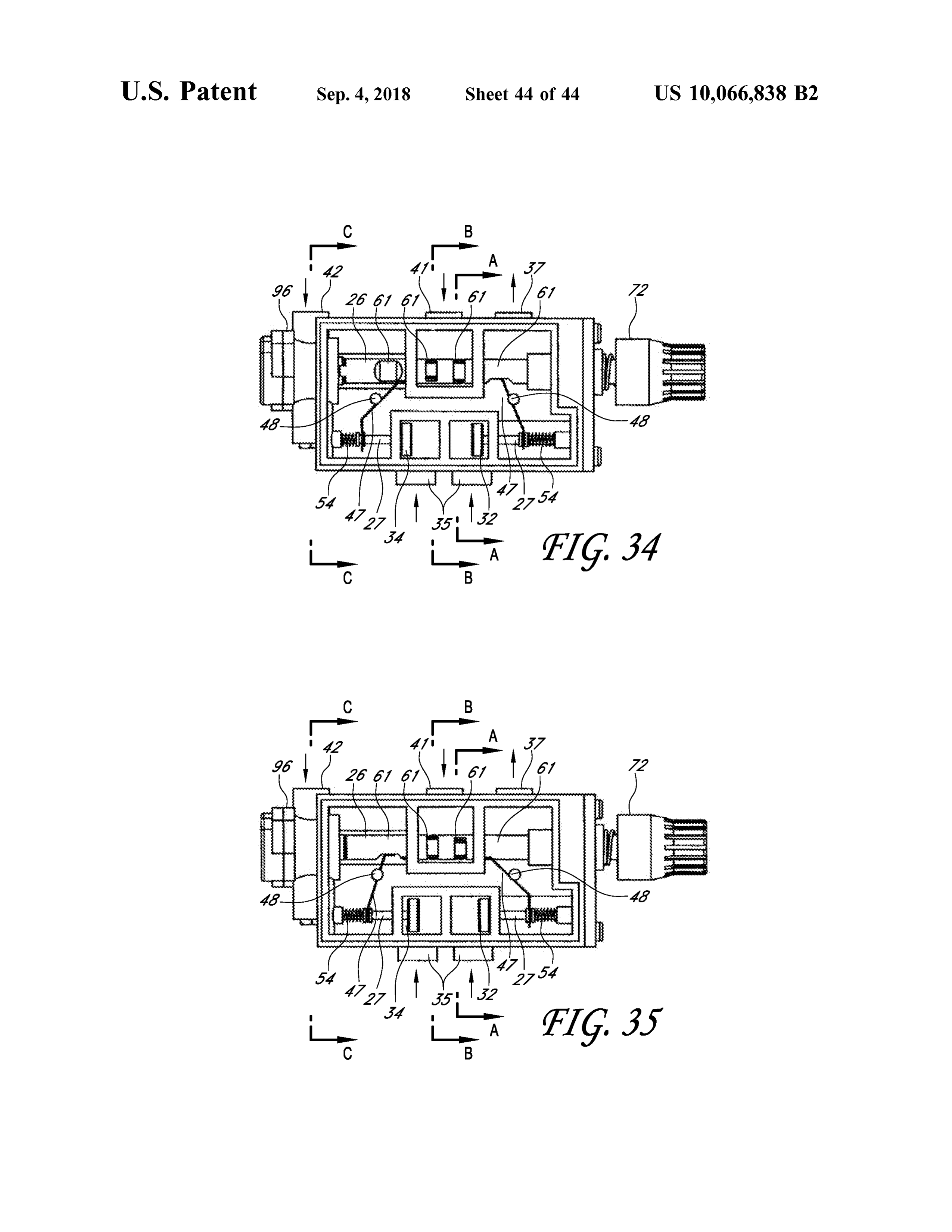
FIGS. 33 , 34 , 35 are schematic and partial cross -sectional views of the heating source of FIG . 32 in a closed , first open
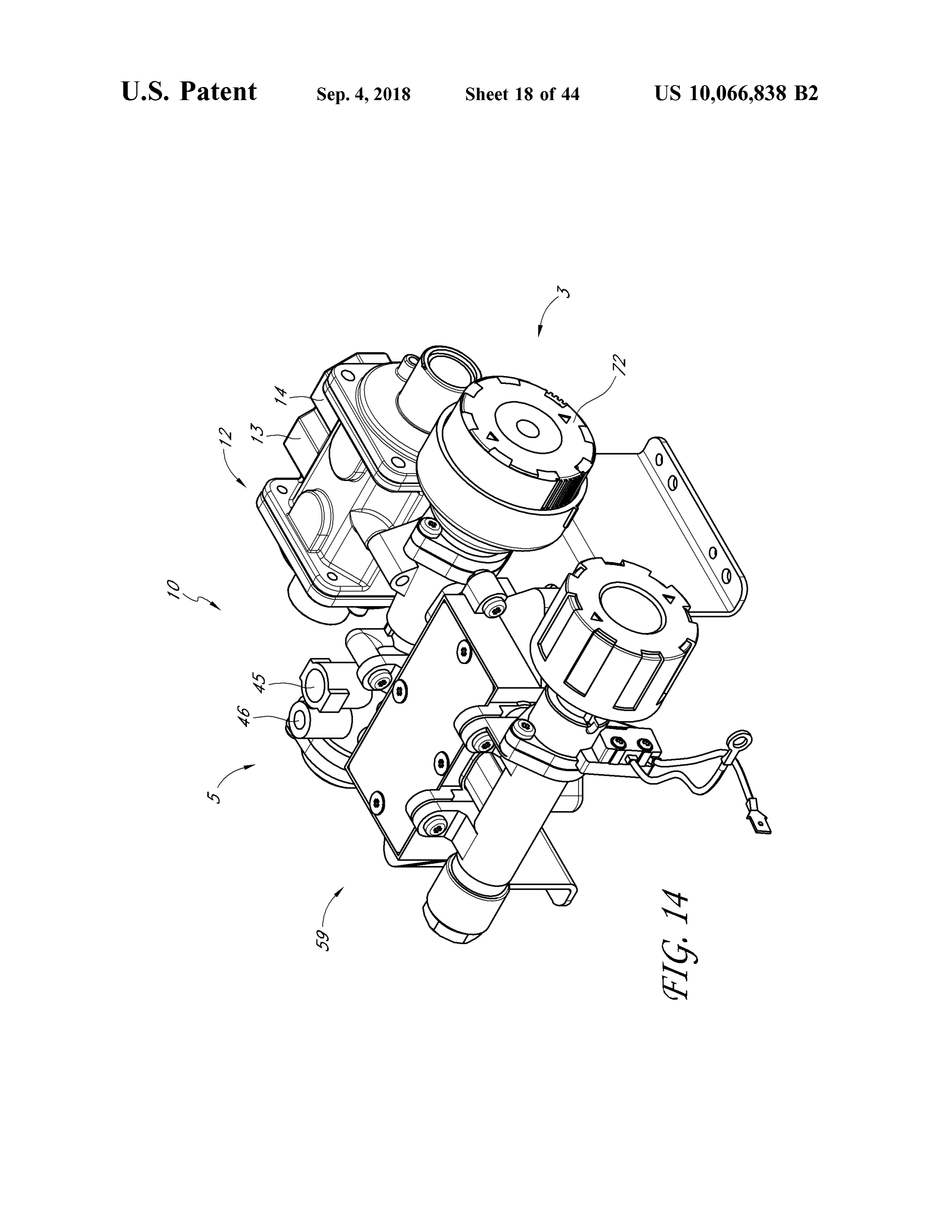
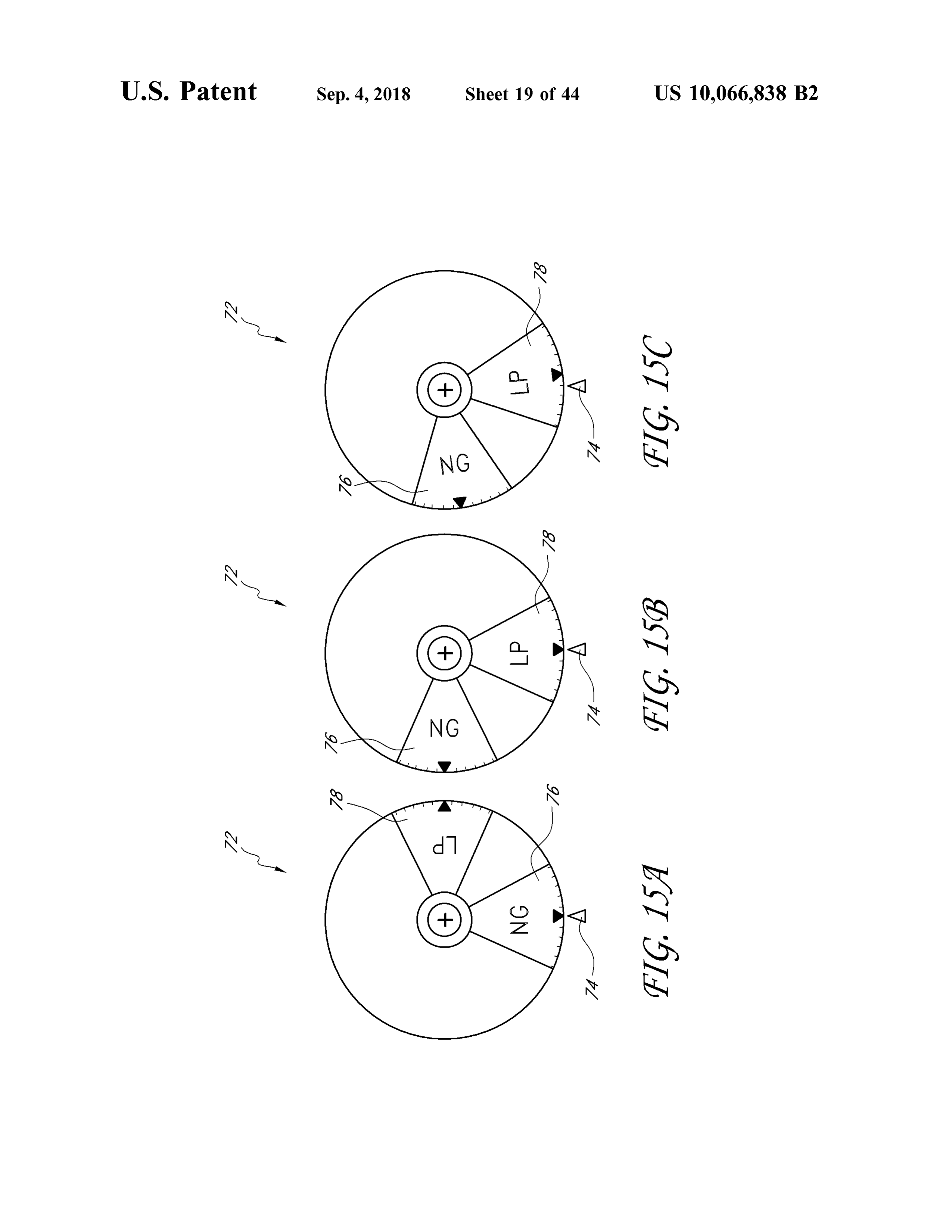
FIGS. 13C - D are top and a side cross -sectional views, 50 and second open configuration , respectively . respectively , of the heating source of FIGS . 13A - B in a FIGS. 33A , 34A , 35A are cross -sectional views taken second position . along line A - A of the respective base FIG . 33 , 34 or 35 . FIG . 14 shows a perspective view of another embodiment FIGS. 33B , 34B , 35B are cross -sectional views taken of a heating source . along line B - B of the respective base FIG . 33 , 34 or 35 . FIGS. 15A - C show different positions of a user interface 55 FIGS. 33C , 34C , 35C are cross -sectional views taken surface. along line C - C of the respective base FIG . 33 , 34 or 35 . FIGS. 15D - E show additional embodiments of a user interface surface. DETAILED DESCRIPTION OF THE
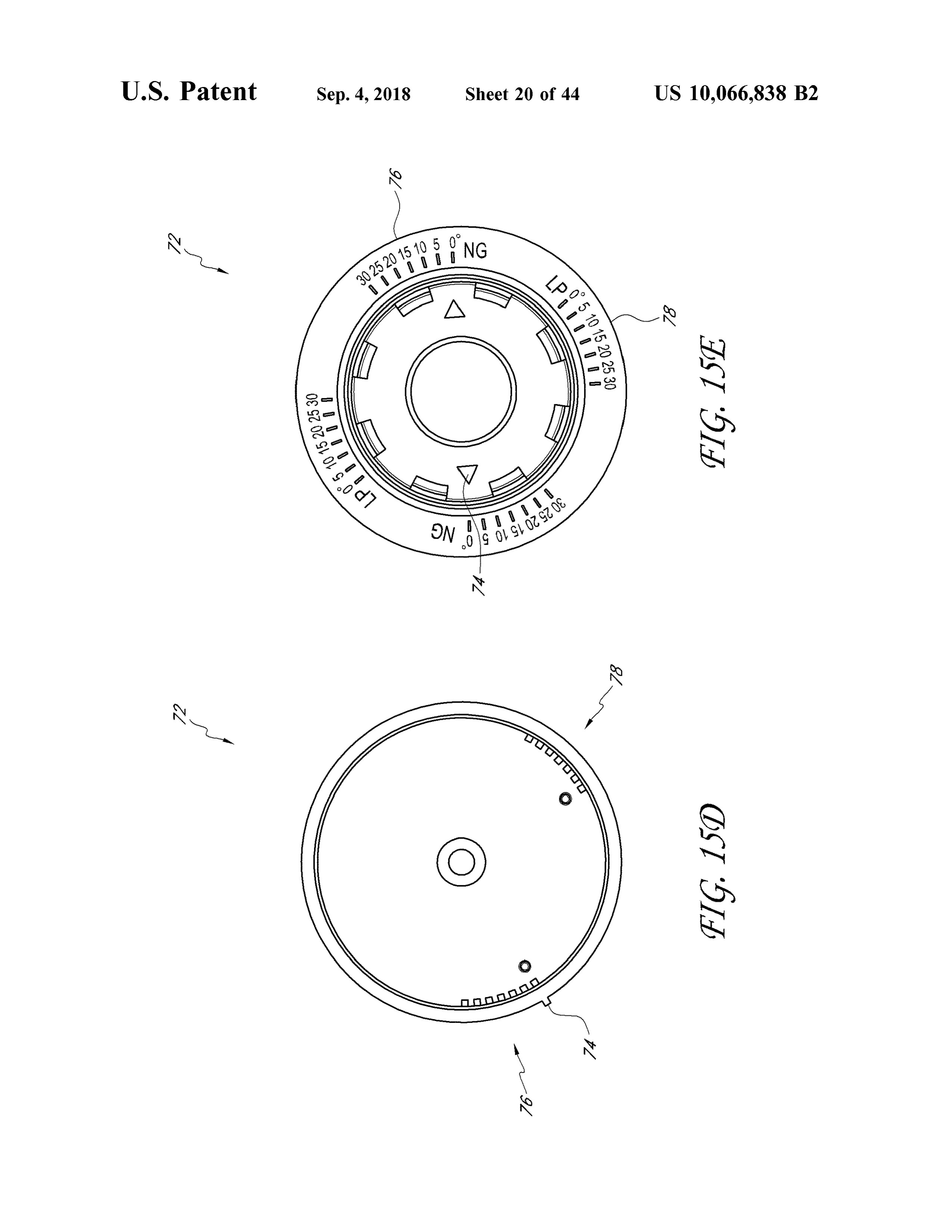
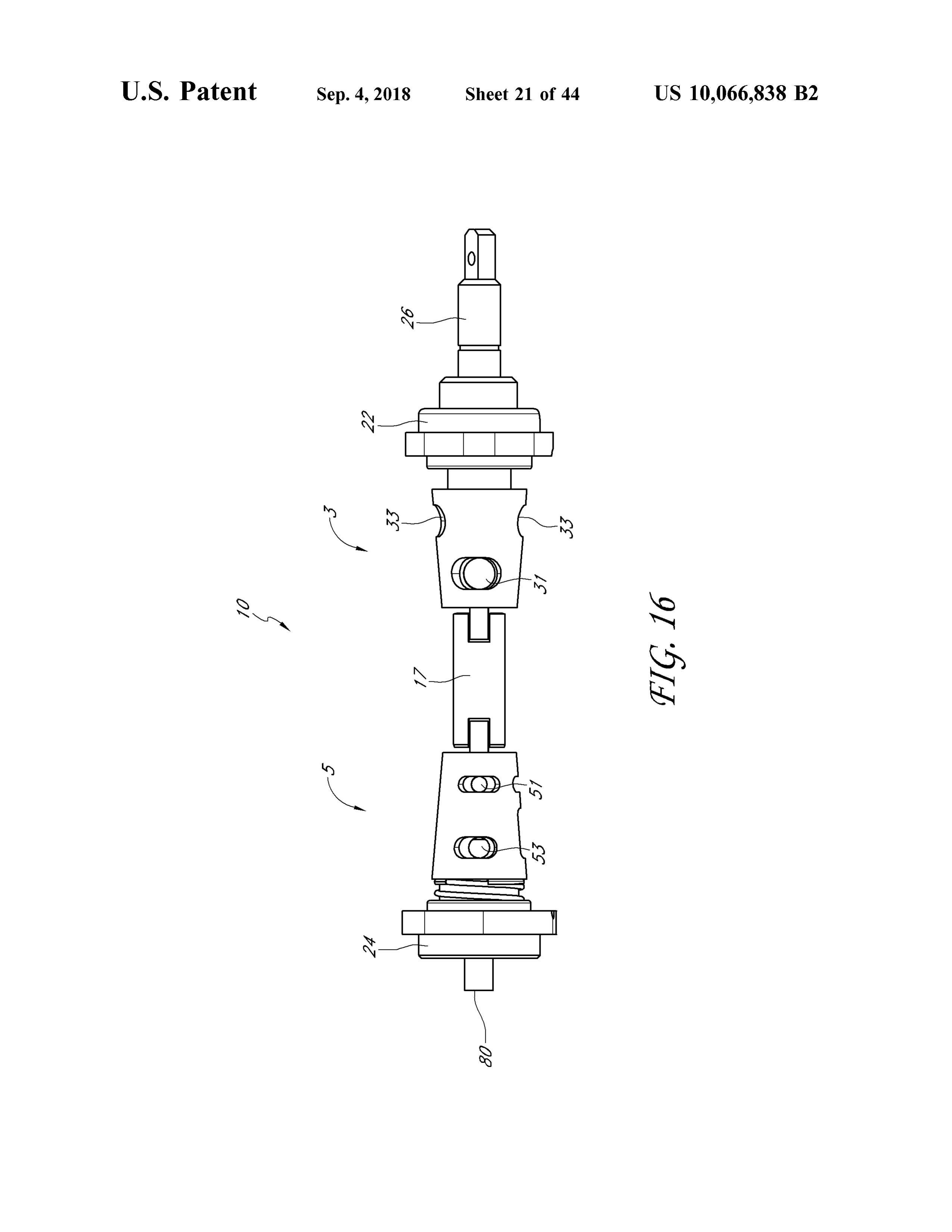
FIG . 16 illustrates another embodiment of a heating PREFERRED EMBODIMENT source with the valve housing removed . 60
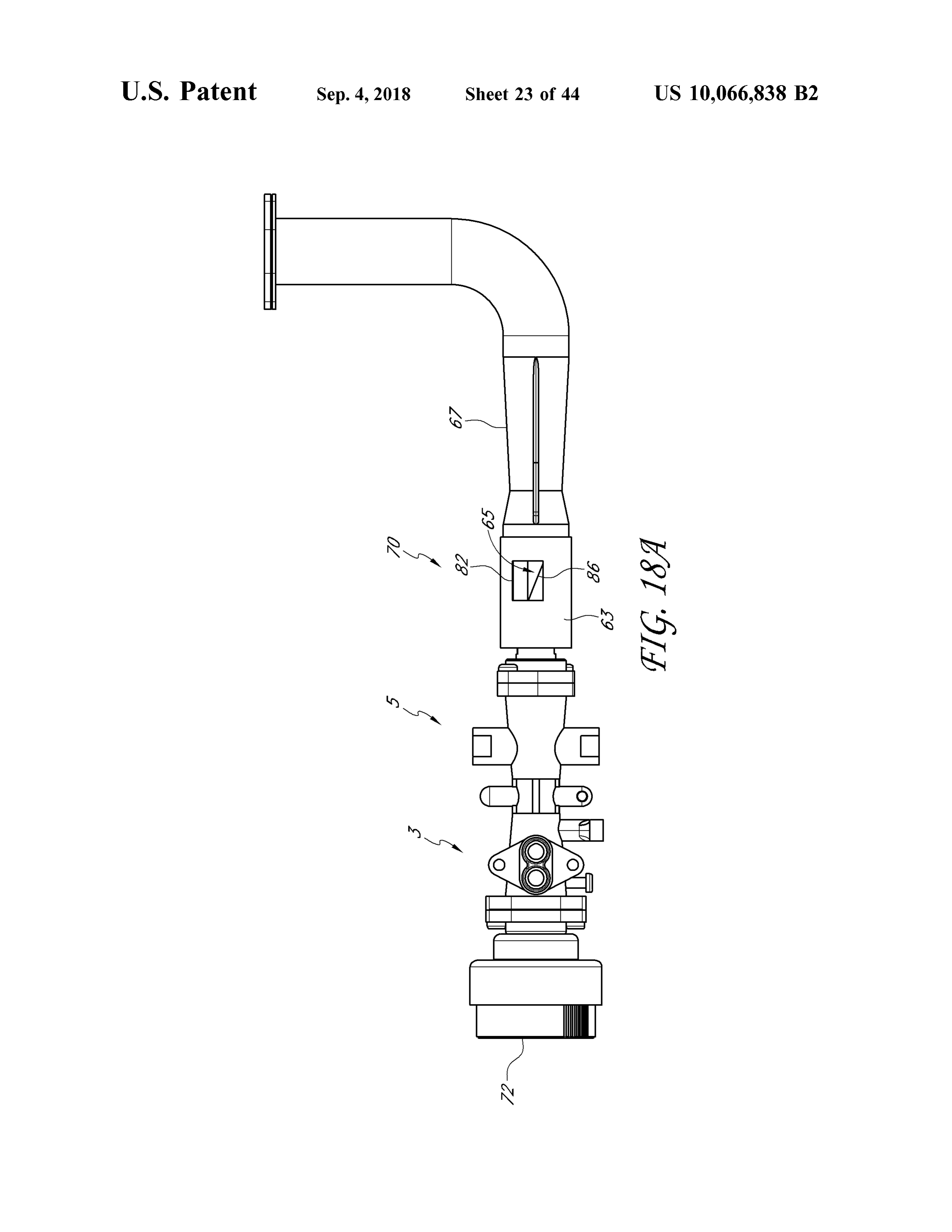
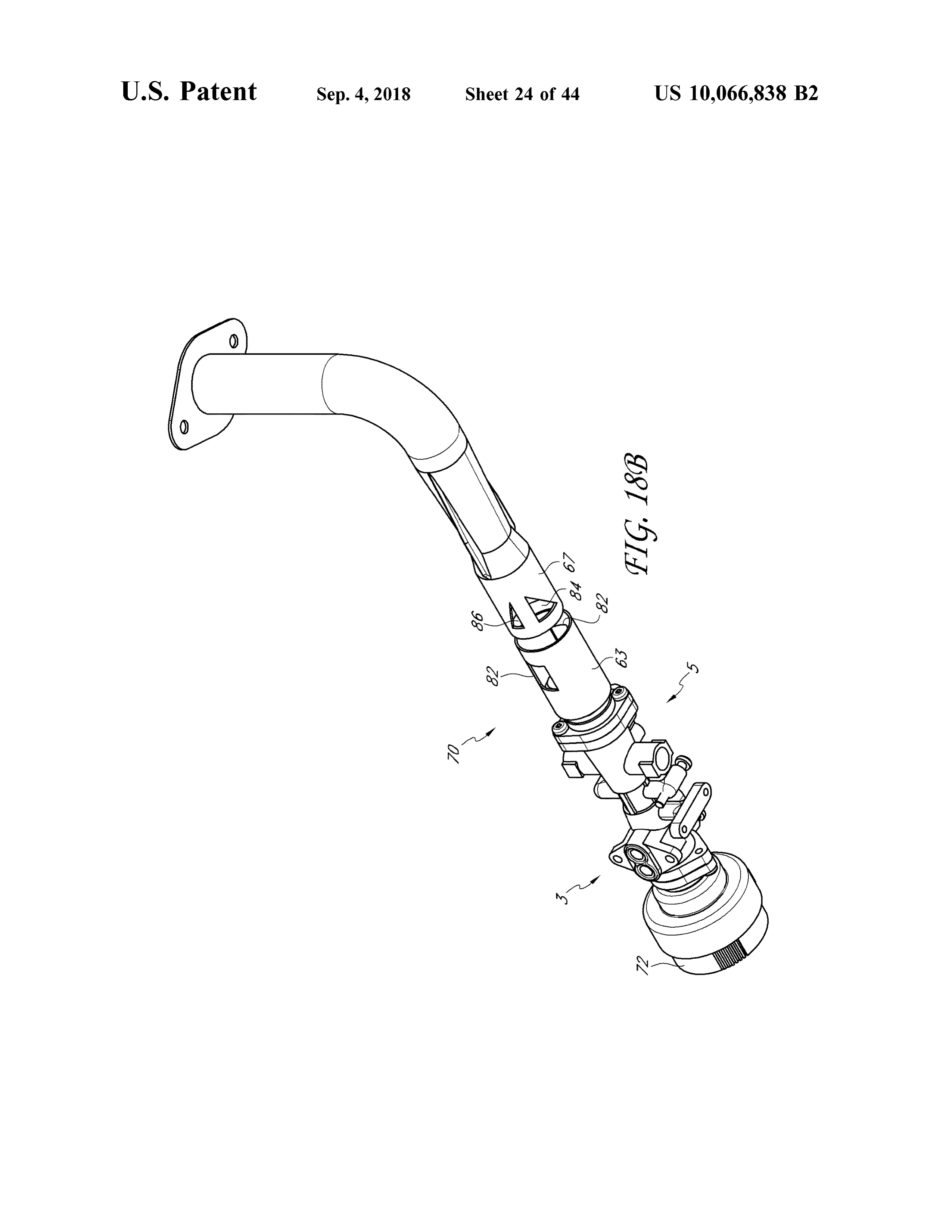
FIGS . 17A - C show different positions of an air shutter. Many varieties of space heaters, fireplaces , stoves , ovens, FIG . 18A is an embodiment of a heating source and air boilers, fireplace inserts, gas logs, and other heat-producing shutter . devices employ combustible fuels, such as liquid propane FIG . 18B is an exploded view of the air shutter of FIG . and natural gas . These devices generally are designed to 18A . 65 operate with a single fuel type at a specific pressure . For FIG . 19 is a schematic representation of a dual fuel direct example , as one having skill in the art would appreciate , vent heater. some gas heaters that are configured to be installed on a wall
Page 52
or a floor operate with natural gas at a pressure in a range and an igniter line 184 , which can be coupled with an igniter from about 3 inches of water column to about 6 inches of switch 186 . Each of the pipes 122 , 124 , and 126 and the lines water column, while others operate with liquid propane at a 141 - 144 can define a fluid passageway or flow channel pressure in a range from about 8 inches of water column to through which a fluid can move or flow .
about 12 inches of water column . 5 In some embodiments , including the illustrated embodi In many instances , the operability of such devices with ment, the heater 100 comprises a burner 190 . The ODS 180 only a single fuel source is disadvantageous for distributors, can bemounted to the burner 190 , as shown . The nozzle 160 retailers , and/ or consumers. For example, retail stores often can be positioned to discharge a fluid , which may be a gas , try to predict the demand for natural gas units versus liquid liquid , or combination thereof into the burner 190 . For propane units over a given season , and accordingly stock 10 purposes of brevity, recitation of the term " gas or liquid " their shelves and/ or warehouses with a percentage of each hereafter shall also include the possibility of a combination variety of device . Should such predictions prove incorrect of a gas and a liquid . In addition , as used herein , the term stores can be left with unsold units when the demand for one “ fluid ” is a broad term used in its ordinary sense , and type of unit was less than expected, while some potential includes materials or substances capable of fluid flow , such customers can be left waiting through shipping delays or 15 as gases, liquids, and combinations thereof. even be turned away empty -handed when the demand for Where the heater 100 is a dual fuel heater , either a first or one type of unit was greater than expected . Either case can a second fluid is introduced into the heater 100 through the result in financial and other costs to the stores . Additionally, regulator 120 . Still referring to FIG . 2 , the first or the second some consumers can be disappointed to discover that the fluid proceeds from the regulator 120 through the intake pipe styles or models of stoves, fireplaces or other device , with 20 122 to the heater control valve 130. The heater control valve which they wish to improve their homes , are incompatible 130 can permit a portion of the first or the second fluid to with the fuel sources with which their homes are serviced . flow into the fuel supply pipe 124 and permit another portion Certain advantageous embodiments disclosed herein of the first or the second fluid to flow into the ODS pipe 126 . reduce or eliminate these and other problems associated with From the heater control valve 130 , the first or the second devices having heating sources that operate with only a 25 fluid can proceed to the fluid flow controller 140. In many single type of fuel source . Furthermore , although certain of embodiments , the fluid flow controller 140 is configured to the embodiments described hereafter are presented in the channel the respective portions of the first fluid from the fuel context of vent- free heating systems, the apparatus and supply pipe 124 to the first nozzle line 141 and from the devices disclosed and enabled herein can benefit a wide ODS pipe 126 to the first ODS line 143 when the fluid flow variety of other applications and appliances. 30 controller 140 is in a first state , and is configured to channel FIG . 1 illustrates one embodiment of a heater 100 . The the respective portions of the second fluid from the fuel heater 100 can be a vent- free infrared heater, a vent -free blue supply pipe 124 to the second nozzle line 142 and from the flameheater, or some other variety ofheater, such as a direct ODS pipe 126 to the second ODS line 144 when the fluid vent heater. Some embodiments include boilers, stoves , flow controller 140 is in a second state . dryers, fireplaces , gas logs , etc . Other configurations are also 35 In certain embodiments , when the fluid flow controller possible for the heater 100 . In many embodiments , the 140 is in the first state , a portion of the first fluid proceeds heater 100 is configured to be mounted to a wall or a floor through the first nozzle line 141, through the nozzle 160 and or to otherwise rest in a substantially static position . In other is delivered to the burner 190 , and a portion of the first fluid embodiments, the heater 100 is configured to move within a proceeds through the first ODS line 143 to the ODS 180 . limited range . In still other embodiments , the heater 100 is 40 Similarly , when the fluid flow controller 140 is in the second portable . state , a portion of the second fluid proceeds through the The heater 100 can comprise a housing 200 . The housing nozzle 160 and another portion proceeds to the ODS 180 . As 200 can include metal or some other suitable material for discussed in more detail below , other configurations are also providing structure to the heater 100 without melting or possible .
otherwise deforming in a heated environment. In the illus - 45 A heating assembly or heating source 10 that can be used trated embodiment, the housing 200 comprises a window with the heater 100, or other gas appliances , will now be 220 , one or more intake vents 240 and one or more outlet described . The heating source 10 can be configured such that vents 260. Heated air and/ or radiant energy can pass through the installer of the gas appliance can connect the assembly the window 220 . Air can flow into the heater 100 through the to one of two fuels , such as either a supply of natural gas one or more intake vents 240 and heated air can flow out of 50 (NG ) or a supply of propane (LP ) and the assembly will the heater 100 through the outlet vents 260 . desirably operate in the standard mode (with respect to With reference to FIG . 2 , in certain embodiments , the efficiency and flame size and color) for either gas. heater 100 includes a regulator 120 . The regulator 120 can Looking at FIGS . 3 - 5 , a heating source 10 can comprise be coupled with an output line or intake line, conduit , or pipe a fuel selector valve 3 . The fuel selector valve 3 can be for 122 . The intake pipe 122 can be coupled with a heater 55 selecting between two different fuels. The fuel selector valve control valve 130 , which , in some embodiments, includes a 3 can have a first mode configured to direct a flow of a first knob 132 . As illustrated , the heater control valve 130 is fuel (such as NG ) in a first path through the fuel selector coupled to a fuel supply pipe 124 and an oxygen depletion valve 3 and a second mode configured to direct a flow of a sensor (ODS ) pipe 126 , each of which can be coupled with second fuel ( such as LP ) in a second path through the fuel a fluid flow controller 140 . The fluid flow controller 140 can 60 selector valve 3. For example, the fuel selector valve 3 can be coupled with a first nozzle line 141, a second nozzle line have a firstmode configured to permit a flow of a first fuel 142 , a first ODS line 143, and a second ODS line 144 . In (such as NG ) through the fuel selector valve 3 and to prevent some embodiments, the first and the second nozzle lines a flow of a second fuel (such as LP ) therethrough and a 141, 142 are coupled with a nozzle 160 , and the first and the second mode configured to permit a flow of the second fuel second ODS lines 143 , 144 are coupled with an ODS 180 . 65 through the fuel selector valve 3 and to prevent a flow of the In some embodiments , the ODS comprises a thermocouple first fuel therethrough . In some embodiments , including the 182, which can be coupled with the heater control valve 130 , illustrated embodiment, the first and second modes comprise
Page 53
first and second positions of the fuel selector valve 3 . The the first pressure regulator 13 can be set to provide a pressure fuel selector valve 3 can also be used to perform other in the range from about 3 inches of water column to about functions as will be described later on in this specification . 6 inches of water column , including all values and sub The heating assembly 10 can further comprise first and ranges therebetween . In some embodiments, the threshold or second fuel source connections 15 . The heating assembly 10 5 flow -terminating pressure is about 3 inches ofwater column, can connect to one of two different fuel sources , each fuel about 4 inches of water column, about 5 inches of water source having a different type of fuel therein . For example , column , or about 6 inches of water column. one fuel source can be a cylinder of LP and another fuel In some embodiments, the second pressure regulator 14 source can be a NG fuel line in a house, connected to a city can be configured to provide a second pressure in the range gas line . In some embodiments, the first and second fuel 10 from about 8 inches of water column to about 12 inches of source connections 15 comprise first and second pressure regulators 13 , 14 . In some embodiments, the first and second water column, including all values and sub - ranges therebe tween . In some embodiments, the second threshold or flow pressure regulators 13 , 14 are separate and in some embodi terminating pressure is about equal to 8 inches of water ments, they are connected in a joint regulator unit 12 . In still other embodiments, the pressure regulator can be adjustable 15 column, about 9 inches of water column, about 10 inches of so that one fuel source connection can be used for different water column, about 11 inches ofwater column, or about 12 fuels. inches of water column.
In some embodiments , including the illustrated embodi When natural gas is the first fuel and propane is the ment, the fuel selector valve 3 can have a first position second fuel, the first pressure , pressure range and threshold configured for permitting a flow of the first fuel from the first 20 pressure are less than the second pressure , pressure range pressure regulator 13 through the fuel selector valve 3 and and threshold pressure. Stated differently, in some embodi preventing a flow of the second fuel therethrough ; and a ments , when natural gas is the first fuel and propane is the second position configured for permitting a flow of the second fuel, the second pressure , pressure range and thresh second fuel from the second pressure regulator 14 through old pressure are greater than the first pressure , pressure the fuel selector valve 3 and preventing a flow of the first 25 range and threshold pressure .
fuel therethrough . Advantageously, the regulator unit 12 , by comprising first The pressure regulators 13 , 14 can function in a similar and second pressure regulators 13 , 14 which are selectively manner to those discussed in U .S . application Ser. No . and independently operable , facilitates a single heater unit 11/ 443 , 484, filed May 30 , 2006 , now U . S . Pat. No . 7 ,607 , being efficaciously used with different fuel sources . This 426 , incorporated herein by reference and made a part of this 30 desirably saves on inventory costs, offers a retailer or store specification ; with particular reference to the discussion on to stock and provide a single unit that is usable with more pressure regulators at columns 3 - 9 and FIGS. 3 - 7 of the than one fuel source , and permits customers the convenience issued patent. The regulator unit 12 can incorporate the two of readily obtaining a unit which operates with the fuel separate pressure regulators 13 , 14 into one unit , maintain source of their choice . The particular fuel pressure operating ing separate inlets and outlets for each pressure regulator 13, 35 range is desirably factory -preset to provide an adaptable and 14 through the unit 12 , resulting in a two in -two out versatile heater .
configuration . The regulator unit 12 , like the other parts of the heating The pressure regulators 13 , 14 can be preset at the assembly 10 , can comprise a wide variety of suitably durable manufacturing site , factory , or retailer to operate with materials. These include, but are not limited to , metals, selected fuel sources. In many embodiments , the regulator 40 alloys, ceramics , plastics , among others . In one embodi unit 12 includes one or more caps to prevent consumers from ment, the regulator unit 12 comprises a metal or alloy such altering the pressure settings selected by the manufacturer. as aluminum or stainless steel . Various suitable surface Optionally , the heater 100 and/ or the regulator unit 12 can be treatments and finishes may be applied with efficacy , as configured to allow an installation technician and /or user or needed or desired .
customer to adjust the heater 100 and/ or the regulator unit 12 45 In certain embodiments, the regulator unit 12 , like the to selectively regulate the heater unit for a particular fuel other parts of the heating assembly 10 , can be fabricated or source . created using a wide variety of manufacturing methods, In some embodiments , the pressure regulators 13 , 14 are techniques and procedures . These include , but are not lim selectively and independently operable which are indepen - ited to , casting, molding, machining, laser processing ,mill dently operated depending on the fuel source , such as, but 50 ing , stamping, laminating , bonding, welding , and adhesively not limited to , natural gas and propane. In some embodi- fixing, among others .
ments, the first pressure regulator 13 comprises a first The heating source 10 can have : 1 ) two pressure regula spring -loaded valve or valve assembly and the second tors 13 , 14 , each configured to connect to a different fuel pressure regulator 14 comprises a second spring -loaded (such as NG on one and LP on the other ) and 2 ) a fuel valve or valve assembly . 55 selector valve 3 , with no pipes in -between 1 and 2 , as shown The pressure settings can be set by tensioning of a screw in FIG . 3 . The fuel selector valve 3 can permit the flow of that allows for flow control of the fuel at a predetermined fuel from one of the two pressure regulators, through the fuel pressure or pressure range and selectively maintains an selector valve 3 and into additional components 9 . The orifice open so that the fuel can flow through spring -loaded additional components 9 can be, for example , the heater valve or valve assembly of the pressure regulator. If the 60 control valve 130 , the fluid flow controller 140, the nozzle pressure exceeds a threshold pressure , a plunger seat can be 160 , etc . In some embodiments, the additional components pushed towards a seal ring to seal off the orifice , thereby 9 can comprise a control valve which comprises at least one closing the pressure regulator. of a manual valve , a thermostat valve , an AC solenoid , a DC The pressure selected depends at least in part on the solenoid and a flame adjustment motor. In various embodi particular fuel used , and may desirably provide for safe and 65 ments, the additional components 9 may or may not com efficient fuel combustion and reduce, mitigate , or minimize prise part of the heating source 10 . The additional compo undesirable emissions and pollution . In some embodiments, nents 9 can be configured to use the fuel, such as for
Page 54
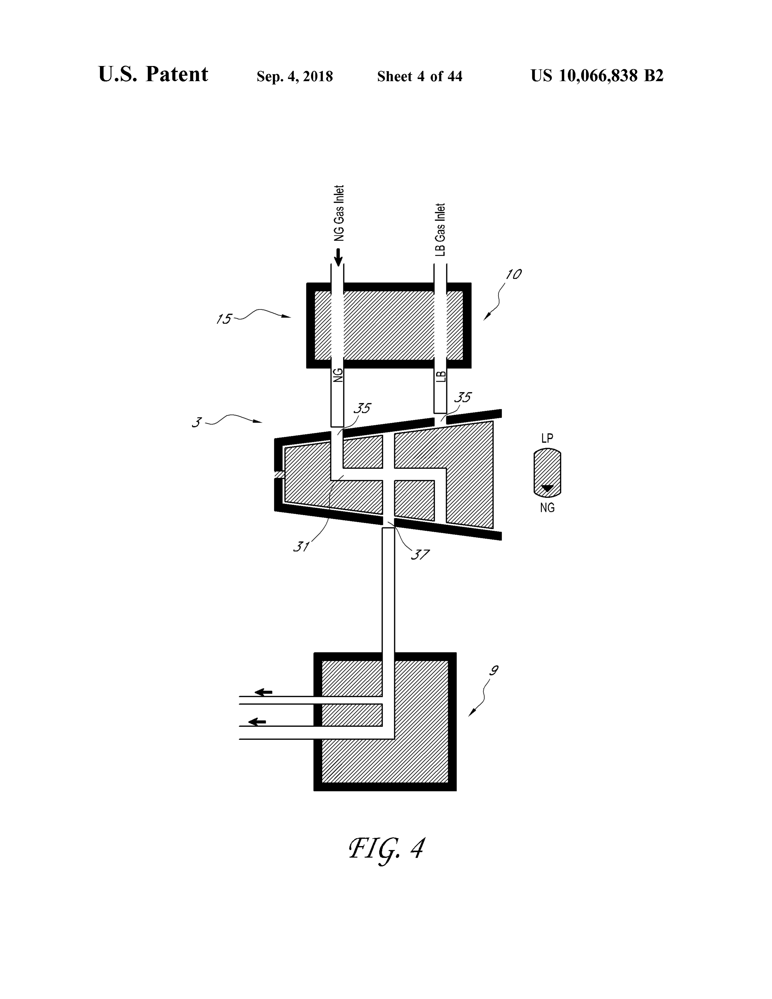
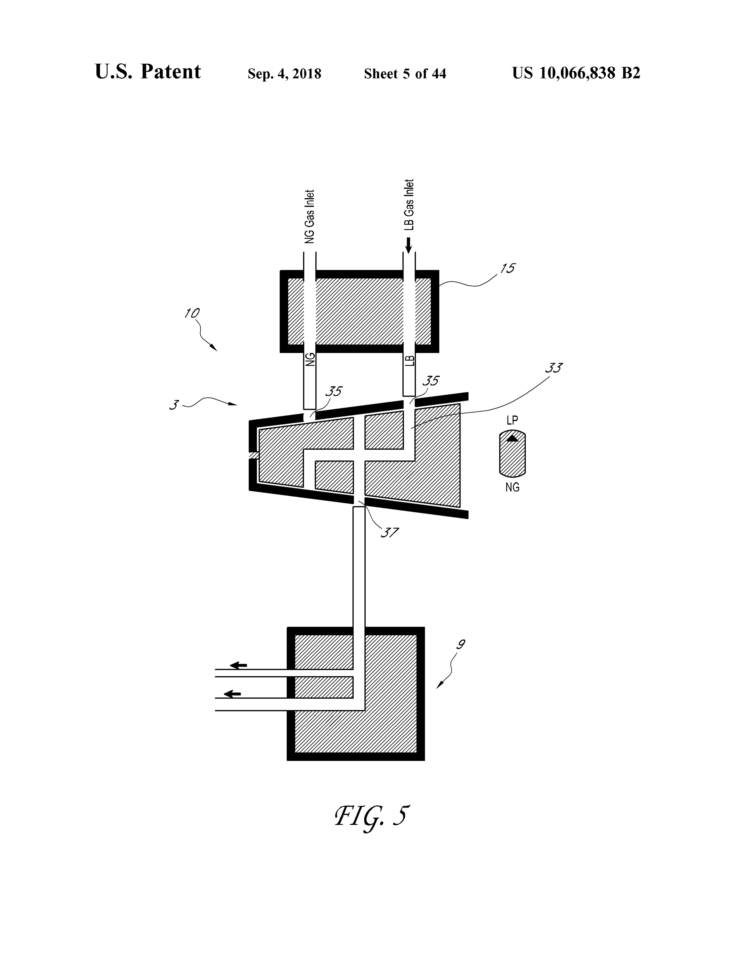
combustion , and /or to direct one or more lines of fuel to between directing fuel towards a first pilot light or a first other uses or areas of the heater 100 or other appliance . oxygen depletion sensor configured for a first fuel or a FIGS. 4 and 5 show schematic diagrams of a heating second pilot light or a second oxygen depletion sensor source 10 wherein different fuels, NG or LP are selected . A configured for a second fuel. Alternatively , the outlet valve rotating valve is represented where in a first position a 5 5 could direct fuel to particular flow paths configured for the passageway 31 allows the first gas, shown as NG in FIG . 4 , particular fuel.
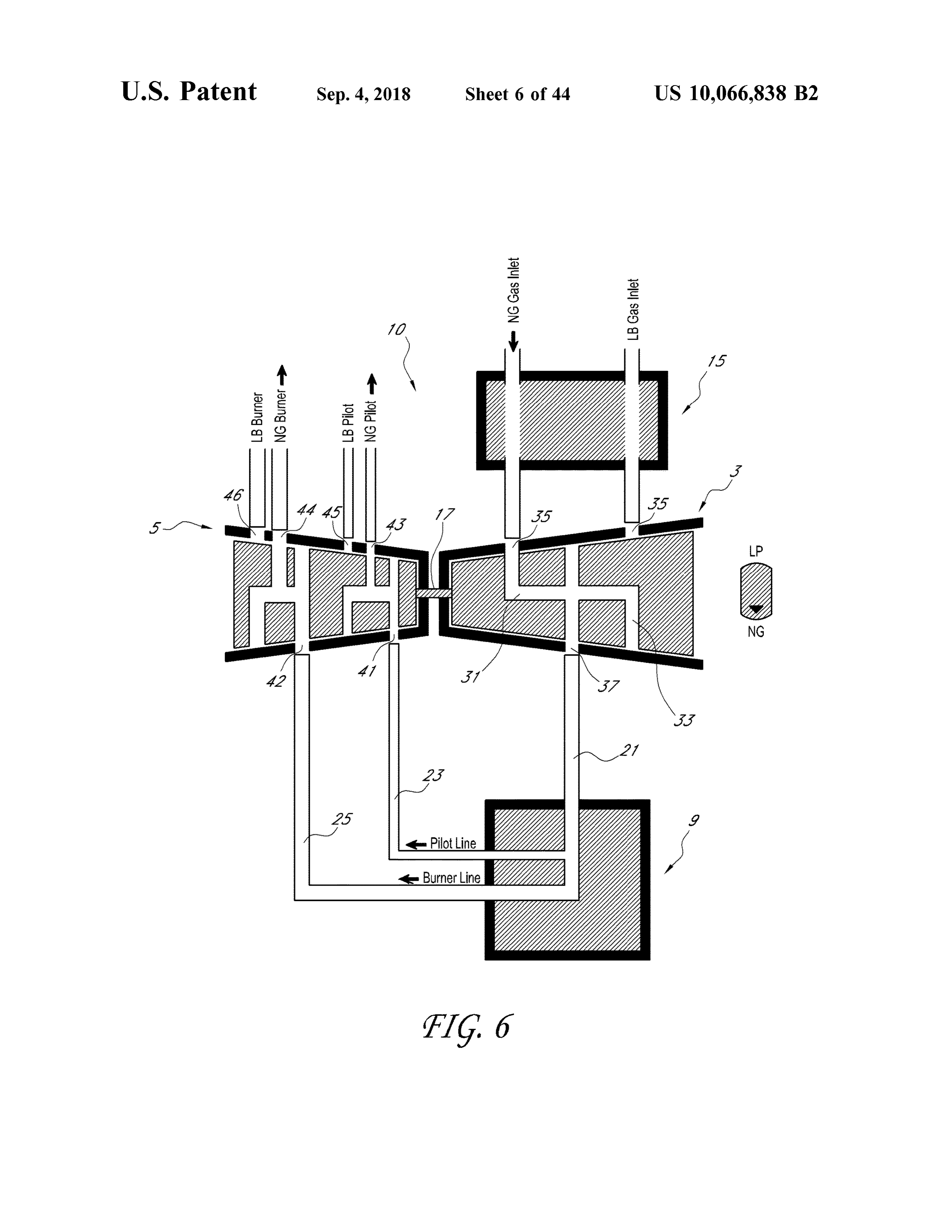
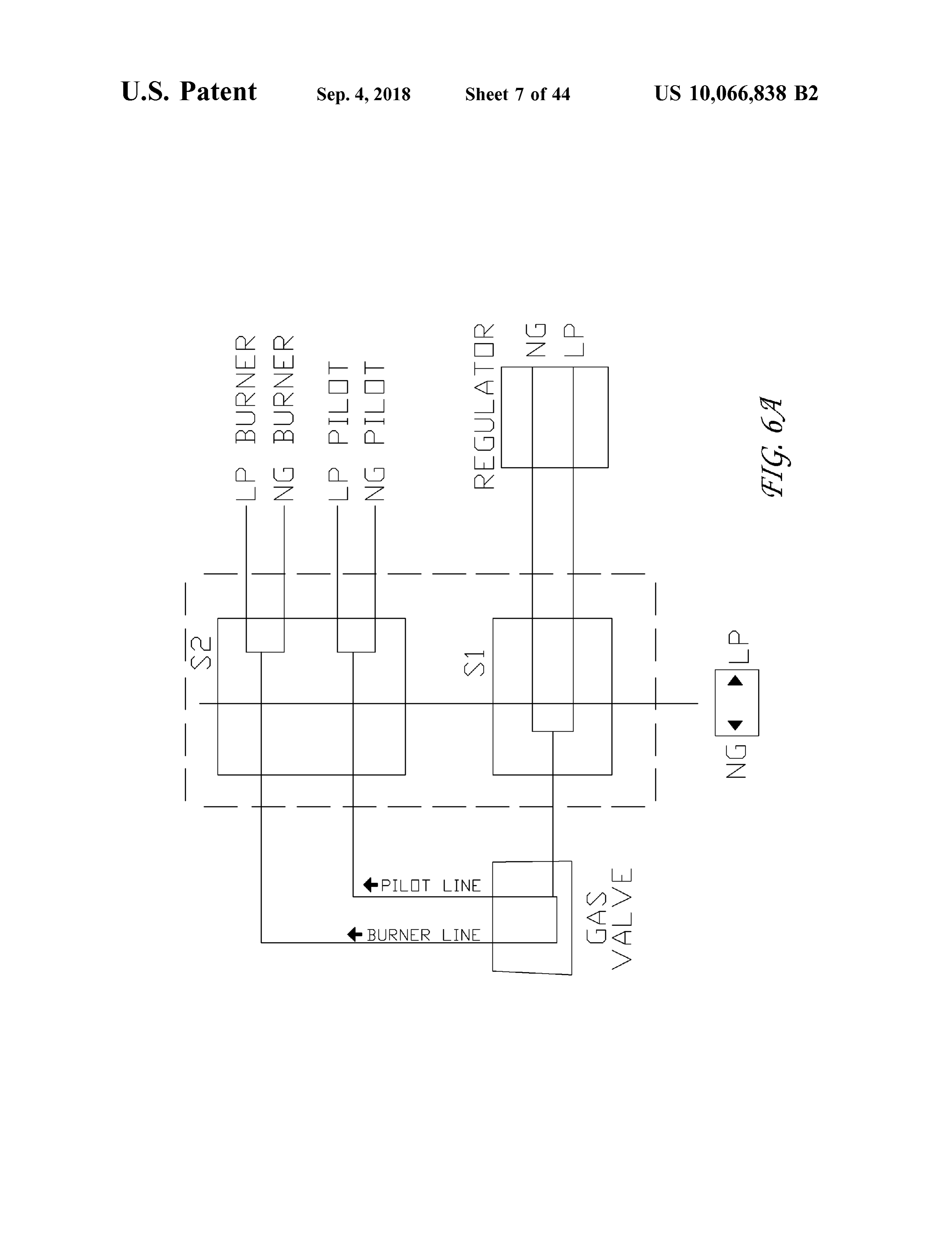
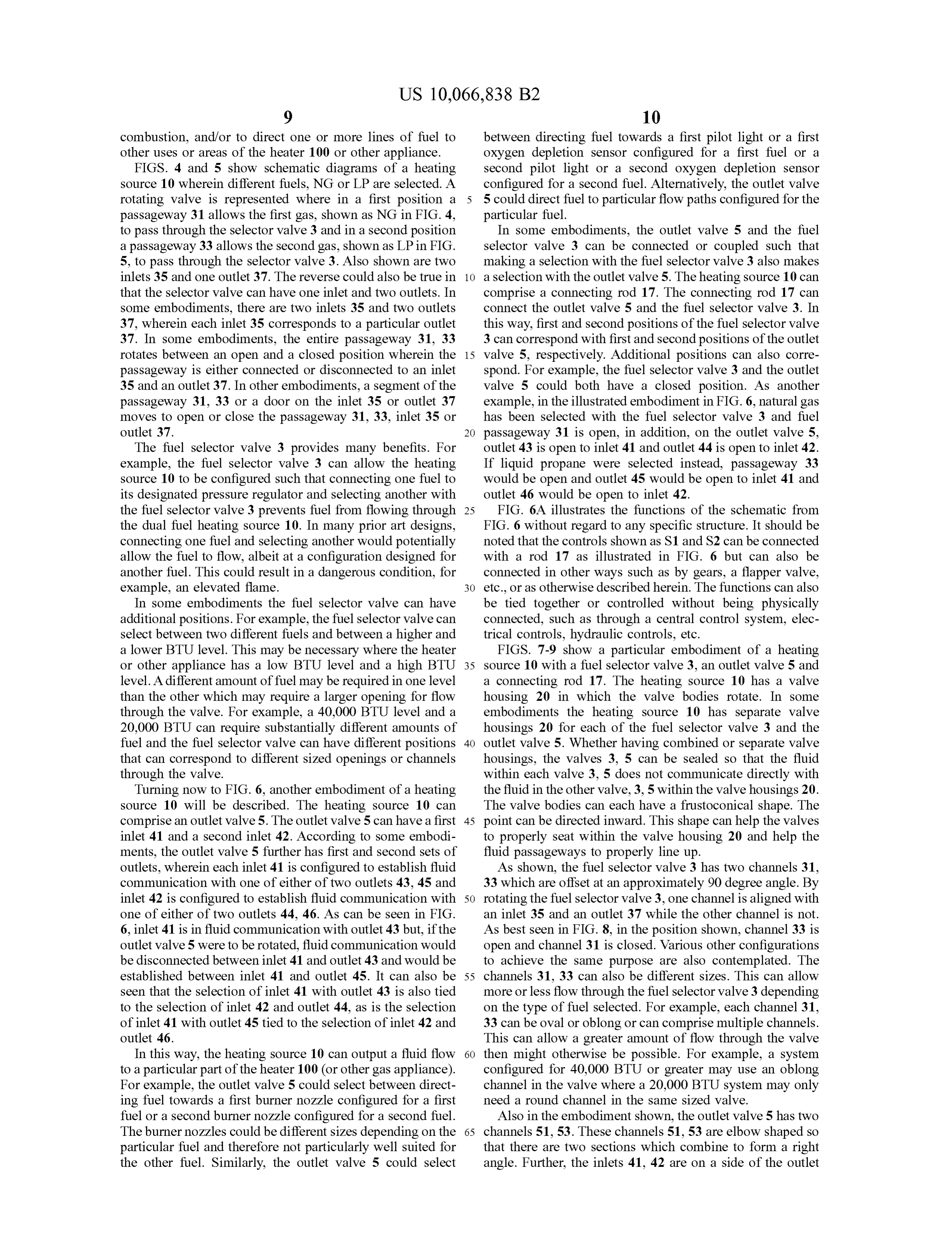
to pass through the selector valve 3 and in a second position In some embodiments, the outlet valve 5 and the fuel a passageway 33 allows the second gas, shown as LP in FIG . selector valve 3 can be connected or coupled such that 5 , to pass through the selector valve 3 . Also shown are two making a selection with the fuel selector valve 3 also makes inlets 35 and one outlet 37 . The reverse could also be true in 10 a selection with the outlet valve 5 . Theheating source 10 can that the selector valve can have one inlet and two outlets . In comprise a connecting rod 17 . The connecting rod 17 can some embodiments, there are two inlets 35 and two outlets connect the outlet valve 5 and the fuel selector valve 3 . In 37 , wherein each inlet 35 corresponds to a particular outlet this way, first and second positions of the fuel selector valve 37 . In some embodiments , the entire passageway 31 , 33 3 can correspond with first and second positions of the outlet rotates between an open and a closed position wherein the 15 valve 5 , respectively. Additional positions can also corre passageway is either connected or disconnected to an inlet spond . For example , the fuel selector valve 3 and the outlet 35 and an outlet 37. In other embodiments , a segment of the valve 5 could both have a closed position . As another passageway 31 , 33 or a door on the inlet 35 or outlet 37 example, in the illustrated embodiment in FIG . 6 ,natural gas moves to open or close the passageway 31 , 33 , inlet 35 or has been selected with the fuel selector valve 3 and fuel outlet 37 . 20 passageway 31 is open , in addition , on the outlet valve 5 , The fuel selector valve 3 provides many benefits . For outlet 43 is open to inlet 41 and outlet 44 is open to inlet 42. example , the fuel selector valve 3 can allow the heating If liquid propane were selected instead , passageway 33 source 10 to be configured such that connecting one fuel to would be open and outlet 45 would be open to inlet 41 and its designated pressure regulator and selecting another with outlet 46 would be open to inlet 42 . the fuel selector valve 3 prevents fuel from flowing through 25 FIG . 6A illustrates the functions of the schematic from the dual fuel heating source 10 . In many prior art designs , FIG . 6 without regard to any specific structure . It should be connecting one fuel and selecting another would potentially noted that the controls shown as S1 and S2 can be connected allow the fuel to flow , albeit at a configuration designed for with a rod 17 as illustrated in FIG . 6 but can also be another fuel. This could result in a dangerous condition , for connected in other ways such as by gears , a flapper valve , example, an elevated flame. 30 etc ., or as otherwise described herein . The functions can also In some embodiments the fuel selector valve can have be tied together or controlled without being physically additional positions. For example , the fuel selector valve can connected , such as through a central control system , elec select between two different fuels and between a higher and trical controls , hydraulic controls , etc . a lower BTU level. This may be necessary where the heater FIGS. 7 - 9 show a particular embodiment of a heating or other appliance has a low BTU level and a high BTU 35 source 10 with a fuel selector valve 3 , an outlet valve 5 and level. A different amount of fuelmay be required in one level a connecting rod 17 . The heating source 10 has a valve than the other which may require a larger opening for flow housing 20 in which the valve bodies rotate . In some through the valve. For example , a 40 ,000 BTU level and a embodiments the heating source 10 has separate valve 20 ,000 BTU can require substantially different amounts of housings 20 for each of the fuel selector valve 3 and the fuel and the fuel selector valve can have different positions 40 outlet valve 5 . Whether having combined or separate valve that can correspond to different sized openings or channels housings , the valves 3 , 5 can be sealed so that the fluid through the valve . within each valve 3, 5 does not communicate directly with Turning now to FIG . 6 , another embodiment of a heating the fluid in the other valve , 3, 5 within the valve housings 20 . source 10 will be described . The heating source 10 can The valve bodies can each have a frustoconical shape. The comprise an outlet valve 5 . The outlet valve 5 can have a first 45 point can be directed inward . This shape can help the valves inlet 41 and a second inlet 42. According to some embodi- to properly seat within the valve housing 20 and help the ments , the outlet valve 5 further has first and second sets of fluid passageways to properly line up . outlets, wherein each inlet 41 is configured to establish fluid As shown, the fuel selector valve 3 has two channels 31 , communication with one of either of two outlets 43, 45 and 33 which are offset at an approximately 90 degree angle . By inlet 42 is configured to establish fluid communication with 50 rotating the fuel selector valve 3 , one channel is aligned with one of either of two outlets 44 , 46 . As can be seen in FIG . an inlet 35 and an outlet 37 while the other channel is not. 6 , inlet 41 is in fluid communication with outlet 43 but, if the As best seen in FIG . 8 , in the position shown , channel 33 is outlet valve 5 were to be rotated , fluid communication would open and channel 31 is closed . Various other configurations be disconnected between inlet 41 and outlet 43 and would be to achieve the same purpose are also contemplated . The established between inlet 41 and outlet 45 . It can also be 55 channels 31 , 33 can also be different sizes. This can allow seen that the selection of inlet 41 with outlet 43 is also tied more or less flow through the fuel selector valve 3 depending to the selection of inlet 42 and outlet 44 , as is the selection on the type of fuel selected . For example, each channel 31 , of inlet 41 with outlet 45 tied to the selection of inlet 42 and 33 can be oval or oblong or can comprise multiple channels . outlet 46 . This can allow a greater amount of flow through the valve In this way , the heating source 10 can output a fluid flow 60 then might otherwise be possible . For example , a system to a particular part of the heater 100 (or other gas appliance ). configured for 40 ,000 BTU or greater may use an oblong For example , the outlet valve 5 could select between direct - channel in the valve where a 20 , 000 BTU system may only ing fuel towards a first burner nozzle configured for a first need a round channel in the same sized valve. fuel or a second burner nozzle configured for a second fuel. Also in the embodiment shown , the outlet valve 5 has two The burner nozzles could be different sizes depending on the 65 channels 51, 53 . These channels 51 , 53 are elbow shaped so particular fuel and therefore not particularly well suited for that there are two sections which combine to form a right the other fuel. Similarly, the outlet valve 5 could select angle . Further, the inlets 41, 42 are on a side of the outlet
Page 55
valve 5 and the outlets are on the top and the bottom so that an amount of fuel from the fuel selector valve 3 through the inlets can only connect with one of the respective outlets, channel 21. The control valve 59 can divide the flow into either with those on the top or those on the bottom . Thus , the two flows or branches . The two flows or branches can be for outlet valve 5 can change the configuration with a 90 degree different purposes , such as for an oxygen depletion sensor rotation . Looking at FIG . 9 , it can be seen that outlets 45 and 5 (ODS ) 180 and for a burner 190 . In some embodiments, the 46 are open and outlets 43 and 44 are closed . control valve 59 can output an amount of fuel for the ODS The outlet valve 5 can have a first configuration of flow 180 through the channel 23 and an amount of fuel for the channels and a second configuration of flow channels . The burner 190 through channel 25 . The control valve 59 can outlet valve 5 can be axially aligned with the fuel selector manually or automatically control when and how much fuel valve 3 and configured such that rotation of the fuel selector 10 is flowing . In some embodiments , the control valve 59 can 3 valve also rotates the outlet valve 5 . Selecting a fuel with directly connect to the fuel selector valve 3 and the outlet the fuel selector valve 3 can determine which inlet of the fuel valve 5 . In some embodiments, the control valve 59 is selector valve is open to allow flow therethrough of either directly connected to a manifold 57 that is directly con natural gas or liquid propane and can determine the flow nected to the fuel selector valve 3 and the outlet valve 5 . In path of the fuel through the outlet valve 5 by either the first 15 some embodiments , the control valve 59 comprises both a configuration of flow channels or the second configuration manual control valve and an automatic control valve . of flow channels. The heater assembly 10 may produce different color The heating source 10 can have end caps 22 , 24 and a flames . Some embodiments have a blue flame, which is shaft 26 ( FIG . 7 ). The shaft 26 can be used to rotate the generally indicative of high efficiency gas combustion . For valves 3 , 5 and connecting rod 17 to make the desired 20 example , the heating assembly of FIG . 10 can be used to selection . The shaft 26 can pass through the end cap 22 . In produce a blue flame in a vent free heater. Other embodi certain embodiments , other devices or valves can be further m ents have a yellow flame, particularly where air is intro connected to the heating source 10 such that making a duced into the fuel. A yellow flame can appear closer to what selection with the heating source 10 also performs additional many people are familiar with when it comes to fire and actions. One particular device , described in more detail 25 therefore may be more desirable for some people . In some below , can comprise an air shutter control. embodiments, yellow flame is not as efficient as blue flame The outlet valve 5 can also have additional channels 55 because less fuel is combusted . Heaters, such as direct vent which connect to the outlets or are part of the outlets 43 , 44 , heaters, vent free heaters, and builder vent heaters are 45 , 46 . The additional channels 55 can , for example , provide examples of heating sources that might typically have yel additional exit points to direct the flow of fuel from the 30 low flames . Some embodiments with a yellow flame can outlet valve 5 . In some embodiments, the outlet valve 5 can have an air shutter.
comprise one ormore caps 58 . The caps 58 can close off the An air shutter can be used to introduce air into the flow of unused exits such as those from the additional channels 55 fuel prior to combustion . The amount of air that is needed to or the outlets. The additional channels 55 and the caps 58 be introduced depends on the type of fuel used . For example , can increase the versatility of the outlet valve 5 . 35 propane gas needs more air than natural gas to produce a In some embodiments the fuel selector valve can have flame of the same size .
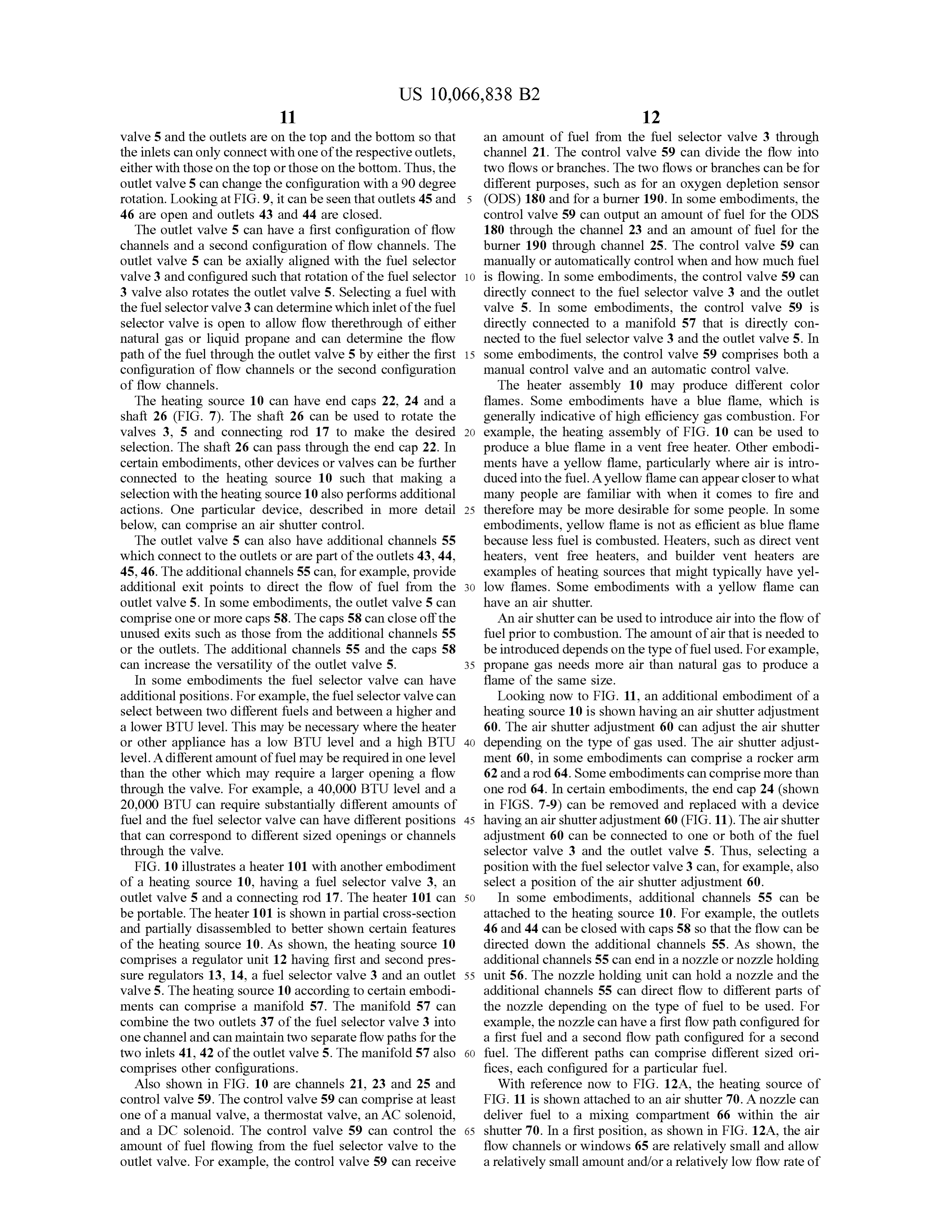
additional positions. For example , the fuel selector valve can Looking now to FIG . 11, an additional embodiment of a select between two different fuels and between a higher and heating source 10 is shown having an air shutter adjustment a lower BTU level. This may be necessary where the heater 60 . The air shutter adjustment 60 can adjust the air shutter or other appliance has a low BTU level and a high BTU 40 depending on the type of gas used . The air shutter adjust level. A different amount of fuelmay be required in one level ment 60 , in some embodiments can comprise a rocker arm than the other which may require a larger opening a flow 62 and a rod 64 . Some embodiments can comprise more than through the valve . For example, a 40 ,000 BTU level and a one rod 64 . In certain embodiments, the end cap 24 (shown 20 ,000 BTU can require substantially different amounts of in FIGS. 7 -9 ) can be removed and replaced with a device fuel and the fuel selector valve can have different positions 45 having an air shutter adjustment 60 (FIG . 11 ). The air shutter that can correspond to different sized openings or channels adjustment 60 can be connected to one or both of the fuel through the valve. selector valve 3 and the outlet valve 5 . Thus, selecting a FIG . 10 illustrates a heater 101 with another embodiment position with the fuel selector valve 3 can , for example , also of a heating source 10 , having a fuel selector valve 3 , an select a position of the air shutter adjustment 60 . outlet valve 5 and a connecting rod 17 . The heater 101 can 50 In some embodiments , additional channels 55 can be be portable . The heater 101 is shown in partial cross -section attached to the heating source 10 . For example , the outlets and partially disassembled to better shown certain features 46 and 44 can be closed with caps 58 so that the flow can be of the heating source 10 . As shown, the heating source 10 directed down the additional channels 55 . As shown, the comprises a regulator unit 12 having first and second pres - additional channels 55 can end in a nozzle or nozzle holding sure regulators 13 , 14 , a fuel selector valve 3 and an outlet 55 unit 56 . The nozzle holding unit can hold a nozzle and the valve 5 . The heating source 10 according to certain embodi- additional channels 55 can direct flow to different parts of ments can comprise a manifold 57 . The manifold 57 can the nozzle depending on the type of fuel to be used . For combine the two outlets 37 of the fuel selector valve 3 into example , the nozzle can have a first flow path configured for one channel and can maintain two separate flow paths for the a first fuel and a second flow path configured for a second two inlets 41, 42 of the outlet valve 5 . The manifold 57 also 60 fuel . The different paths can comprise different sized ori comprises other configurations. fices, each configured for a particular fuel. Also shown in FIG . 10 are channels 21 , 23 and 25 and With reference now to FIG . 12A , the heating source of control valve 59. The control valve 59 can comprise at least FIG . 11 is shown attached to an air shutter 70 . A nozzle can one of a manual valve, a thermostat valve, an AC solenoid , deliver fuel to a mixing compartment 66 within the air and a DC solenoid . The control valve 59 can control the 65 shutter 70 . In a first position , as shown in FIG . 12A , the air amount of fuel flowing from the fuel selector valve to the flow channels or windows 65 are relatively small and allow outlet valve . For example, the control valve 59 can receive a relatively small amount and /or a relatively low flow rate of
Page 56
air therethrough . In some embodiments, as fuel is dispensed prior art heating sources . In some uses, such as blue flame, from the nozzle , air is drawn through the windows 65 . In there is no air shutter and so this is true of the heating source some embodiments, the size of the windows 65 is such that 10 even when it does not have an air shutter or an air shutter the amount of air drawn into the mixing compartment 66 is adjustment.
adequate to form an air- fuel mixture that combusts as a 5 In some embodiments, selecting a fuel with the fuel substantially yellow flame ( e.g., a flame of which a substan selector valve 3 is the only change required to be performed tial portion is yellow ) at the burner. In some embodiments , by an installer to change the heating source 10 from being the heating assembly 10 is configured to dispense natural gas configured for one fuel to another. For example , a heating at a first pressure so as to produce a substantially yellow source 10 can be used in a dual fuel heater designed for use flame at the burner. 10 with either natural gas or liquid propane . The heater can be
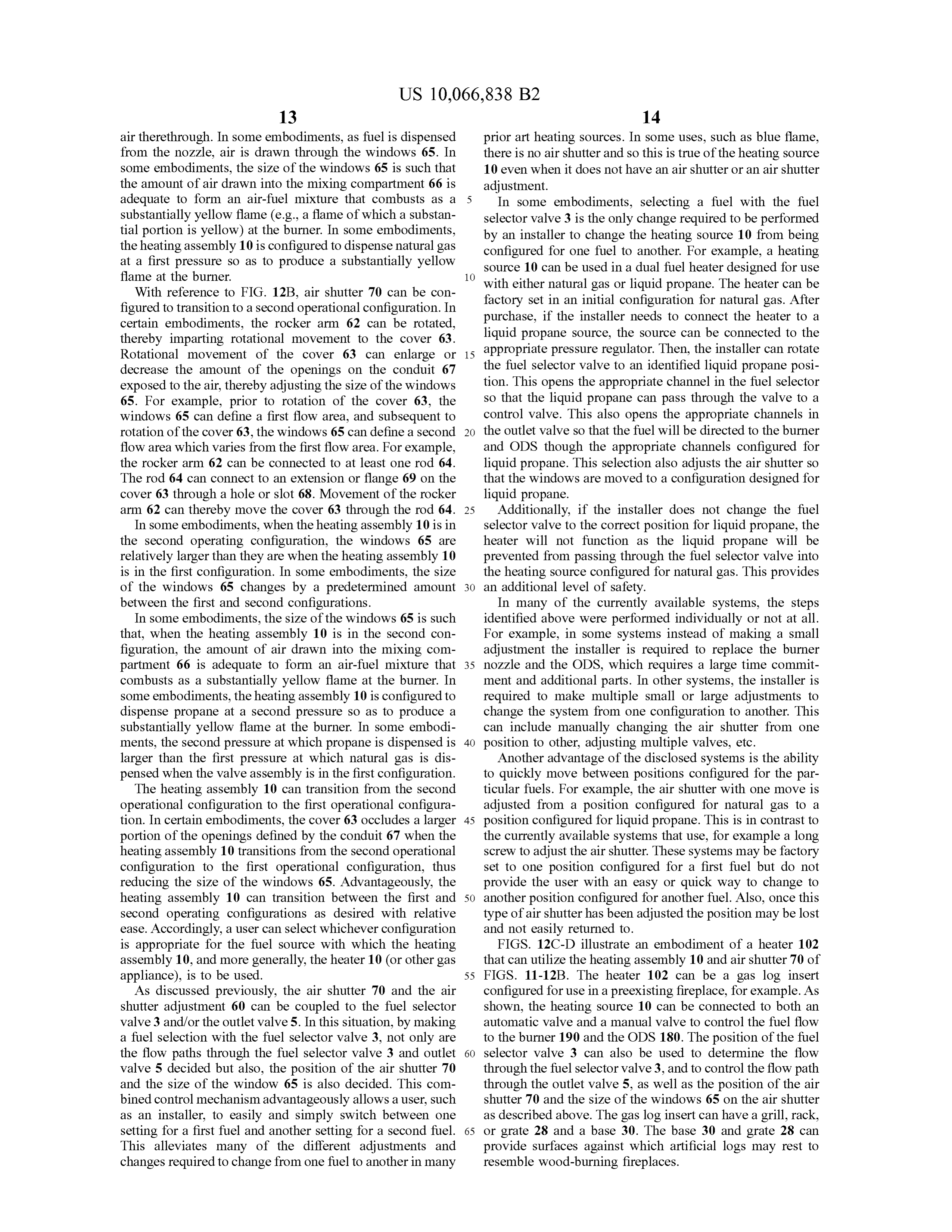
With reference to FIG . 12B , air shutter 70 can be con factory set in an initial configuration for natural gas. After figured to transition to a second operational configuration . In certain embodiments , the rocker arm 62 can be rotated , purchase , if the installer needs to connect the heater to a thereby imparting rotational movement to the cover 63. liquid propane source , the source can be connected to the Rotational movement of the cover 63 can enlarge or 1515 appropriate appropriate pressure pressure reg regulator. Then , the installer can rotate decrease the amount of the openings on the conduit 67 the fuel selector valve to an identified liquid propane posi exposed to the air , thereby adjusting the size of the windows tion . This opens the appropriate channel in the fuel selector 65 . For example , prior to rotation of the cover 63, the so that the liquid propane can pass through the valve to a windows 65 can define a first flow area , and subsequent to control valve . This also opens the appropriate channels in rotation of the cover 63 , the windows 65 can define a second 20 the outlet valve so that the fuel will be directed to the burner flow area which varies from the first flow area . For example , and ODS though the appropriate channels configured for the rocker arm 62 can be connected to at least one rod 64 . liquid propane . This selection also adjusts the air shutter so The rod 64 can connect to an extension or flange 69 on the that the windows are moved to a configuration designed for cover 63 through a hole or slot 68 . Movement of the rocker liquid propane.
arm 62 can thereby move the cover 63 through the rod 64 . 25 Additionally, if the installer does not change the fuel In some embodiments , when the heating assembly 10 is in selector valve to the correct position for liquid propane, the the second operating configuration , the windows 65 are heater will not function as the liquid propane will be relatively larger than they are when the heating assembly 10 prevented from passing through the fuel selector valve into is in the first configuration . In some embodiments , the size the heating source configured for natural gas . This provides of the windows 65 changes by a predetermined amount 30 an additional level of safety .
between the first and second configurations . In many of the currently available systems, the steps In some embodiments, the size of the windows 65 is such identified above were performed individually or not at all . that, when the heating assembly 10 is in the second con - For example , in some systems instead of making a small figuration , the amount of air drawn into the mixing com - adjustment the installer is required to replace the burner partment 66 is adequate to form an air - fuel mixture that 35 nozzle and the ODS , which requires a large time commit combusts as a substantially yellow flame at the burner. In ment and additional parts . In other systems, the installer is some embodiments, the heating assembly 10 is configured to required to make multiple small or large adjustments to dispense propane at a second pressure so as to produce a change the system from one configuration to another. This substantially yellow flame at the burner. In some embodi- can include manually changing the air shutter from one ments, the second pressure at which propane is dispensed is 40 position to other , adjusting multiple valves , etc . larger than the first pressure at which natural gas is dis - Another advantage of the disclosed systems is the ability pensed when the valve assembly is in the first configuration . to quickly move between positions configured for the par The heating assembly 10 can transition from the second ticular fuels . For example , the air shutter with one move is operational configuration to the first operational configura - adjusted from a position configured for natural gas to a tion . In certain embodiments, the cover 63 occludes a larger 45 position configured for liquid propane . This is in contrast to portion of the openings defined by the conduit 67 when the the currently available systems that use , for example a long heating assembly 10 transitions from the second operational screw to adjust the air shutter. These systemsmay be factory configuration to the first operational configuration , thus set to one position configured for a first fuel but do not reducing the size of the windows 65 . Advantageously , the provide the user with an easy or quick way to change to heating assembly 10 can transition between the first and 50 another position configured for another fuel. Also , once this second operating configurations as desired with relative type of air shutter has been adjusted the position may be lost ease . Accordingly, a user can select whichever configuration and not easily returned to .
is appropriate for the fuel source with which the heating FIGS. 12C -D illustrate an embodiment of a heater 102 assembly 10 , and more generally, the heater 10 (or other gas that can utilize the heating assembly 10 and air shutter 70 of appliance ), is to be used . 55 FIGS. 11- 12B . The heater 102 can be a gas log insert As discussed previously , the air shutter 70 and the air configured for use in a preexisting fireplace , for example . As shutter adjustment 60 can be coupled to the fuel selector shown , the heating source 10 can be connected to both an valve 3 and /or the outlet valve 5 . In this situation , by making automatic valve and a manual valve to control the fuel flow a fuel selection with the fuel selector valve 3 , not only are to the burner 190 and the ODS 180 . The position of the fuel the flow paths through the fuel selector valve 3 and outlet 60 selector valve 3 can also be used to determine the flow valve 5 decided but also , the position of the air shutter 70 through the fuel selector valve 3 , and to control the flow path and the size of the window 65 is also decided . This com - through the outlet valve 5 , as well as the position of the air bined control mechanism advantageously allows a user, such shutter 70 and the size of the windows 65 on the air shutter as an installer, to easily and simply switch between one as described above. The gas log insert can have a grill, rack , setting for a first fuel and another setting for a second fuel. 65 or grate 28 and a base 30 . The base 30 and grate 28 can This alleviates many of the different adjustments and provide surfaces against which artificial logs may rest to changes required to change from one fuel to another in many resemble wood -burning fireplaces.
Page 57
FIGS. 13A - D disclose another embodiment of a heater the outlet valve 5 . The air shutter 70 can also be moved to assembly 10 . The heater assembly 10 is shown in cross a position configured for the selected fuel. section to illustrate two different flow paths through the The second adjustment of user interface surface 72 , in heater assembly 10 . FIGS. 13A and B illustrate a first some embodiments , pertains to the air shutter 70 . As dis configuration wherein channels 33 , 45 and 46 are open and 5 cussed previously , the air shutter 70 can be connected to the 31, 43 and 44 are closed . FIGS. 13C and D show a second fuel selector valve 3 and /or the outlet valve 5 with an air configuration wherein channels 31, 43 and 44 are open and shutter adjustment 60. Movement of the valves can move the 33 , 45 and 46 are closed . FIGS. 13A - D also show one air shutter adjustment 60 which in turn moves the air shutter possible configuration of the additional channels 55 leading 70 . The second adjustment of the user interface surface 72 to the nozzle holding unit 56 . 10 can be used for fine tune adjustment of the air shutter 70 . In FIG . 14 , another embodiment of a heating source 10 is This fine tune adjustment can be done without changing or shown . The heating source 10 is illustrated with a regulator modifying the flow of the selected fuel. unit 12 , a fuel selector valve 3 , an outlet valve 5 , and a As mentioned previously , the fuel selection can be done control valve 59 . The control valve 59 comprises both an by moving the user interface surface 72 so that the indicator automatic and a manual control valve . In some embodi- 15 74 is along a fuel region 76 , 78 . The large arrow in the fuel ments, the automatic valve is connected directly to the fuel region can represent a factory setting or a typical setting of selector valve 3 and the outlet valve 5 and the manual valve the air shutter 70 , known to work in many typical situations. is connected directly to the automatic valve . The other markings in the fuel region 76 , 78 can indicate an Certain embodiments of the heating source 10 can also amount of deviation or change from the first position . In have a user interface surface 72 , such as that shown in FIGS . 20 other words, these markings can indicate to a user an 15A - E . The user interface surface can comprise a knob increase or decrease in the size of the windows 65 on the air connected to the shaft 26 . The user interface surface 72, of shutter 70 and thereby an increase or decrease in the amount some embodiments , can control the type of gas. The user of air that can mix with the fuel flow . interface surface 72 , of some embodiments , can control the FIGS. 15D - E illustrate two additional embodiments of amount of air flow . The user interface surface 72 , of some 25 user interface surfaces 72 . In FIG . 15D , the circles indicate embodiments , can control the amount of air flow and the an initial position to be lined up with the indicator 74 type of gas . Manipulation of the user interface surface 72 configured for a particular fuel. From the initial position , the can control the fuel selector valve 3 , the outlet valve 5 and /or user can continue to rotate the user interface surface 72 . the air shutter 70 . In other embodiments , not shown , the user Because the initial position is near the beginning of the fuel interface surface 72 can comprise other types of mechanical 30 region 76 , 78 the adjustment of the air shutter 70 can be to controls such as a lever, a wheel, a switch , or some other either increase or decrease the size of the window 65 from device to transfer a user 's movement to move the desired the initial position . FIG . 15E is similar to FIG . 15D with an valves . In other embodiments , also not shown , the user initial position indicated at zero and showing a degree interface surface 72 can comprise an electrical or computer change from the initial position . For example , as shown , the control, including but not limited to electrical buttons, 35 natural gas (NG ) initial position can be a fully open window electrical switches, a touch screen , etc . or largest window position and the degree change can The user interface surface 72 can be rotated from a first indicate an amount the air shutter is closed from the fully position to a second position . The first position can control open or largest window position . the heating source 10 so that the heating source is configured In some embodiments, the fuel regions 76 , 78 can be for a first fuel. The second position can control the heating 40 within a 30 degree , 45 degree , 50 degree or 60 degree source 10 so that the heating source is configured for a segment of the user interface surface 72 . In some embodi second fuel. The user interface surface 72 can also control ments , a large change in the position of the user interface the heater 100 or other gas appliance . Thus, the first position surface 72 can result in a small adjustment of the air shutter can control the heater 100 so that the heater 100 is config - 70. In some embodiments , the change in position of the user ured for a first fuel and the second position can control the 45 interface surface 72 corresponds to a similar sized change in heater 100 so that the heater 100 is configured for a second the position of the air shutter 70 . fuel. The valves and/or valve housings can be configured to In some embodiments the user interface surface 72 can be account for a range of positions of the valves 3 , 5 for a limited to two positions, a first position for a first fuel and particular fuel. This can allow for adjustment of the air a second position for a second fuel. Other embodiments can 50 shutter without adjusting the flow of fuel through either or have additional positions or configurations , for example , an both of the valve 3 , 5 . FIG . 16 shows part of the heating off position . source 10 from FIG . 14 , with valve housing 20 removed . In FIGS. 15A - C show one embodiment of a user interface this view it can be seen that the size of the openings to the surface 72 . According to some embodiments , the user inter - passageways 31 , 33 , 51, 53 through the valves 3 , 5 have face surface 72 can make two types of adjustments. In an 55 been increased . It can be seen that the openings on both ends initial adjustment, a user, such as an installer, can select the are larger than the rest of the passageway . This can allow the type of fuel. As shown , the user can select between natural air shutter to be adjusted within a range for a particular fuel. gas and liquid propane . This can be done by rotating the user In some embodiments , larger passageways can be used interface surface 72 so that the indicator 74 is pointing to one instead of enlarged openings. The enlarged openings, or of the fuel regions 76 , 78 . If the indicator 74 is anywhere 60 alternatively the enlarged passageways, can be larger than along either fuel region 76 or 78 , that particular fuel is the inlets and outlets on the valves . The inlets and outlets can selected . In FIG . 15A , natural gas (NG ) has been selected . include inlets 35 , 41, 42 and outlets 37 , 43, 44 , 45 , 46 . This In FIGS. 15B and C , liquid propane (LP ) has been selected can allow the valve 3 and/or 5 to function properly within a Depending on the configuration of the heating source 10, range of positions.
the fuel selected by the user interface surface 72 will open 65 The air shutter 70 and the air shutter adjustment 60 can or configure the connected valves , if any, to the appropriate take on many forms. In one embodiment, the air shutter setting. Preferably this includes the fuel selector valve 3 and adjustment 60 is coupled to the outlet valve 5 with a screw .
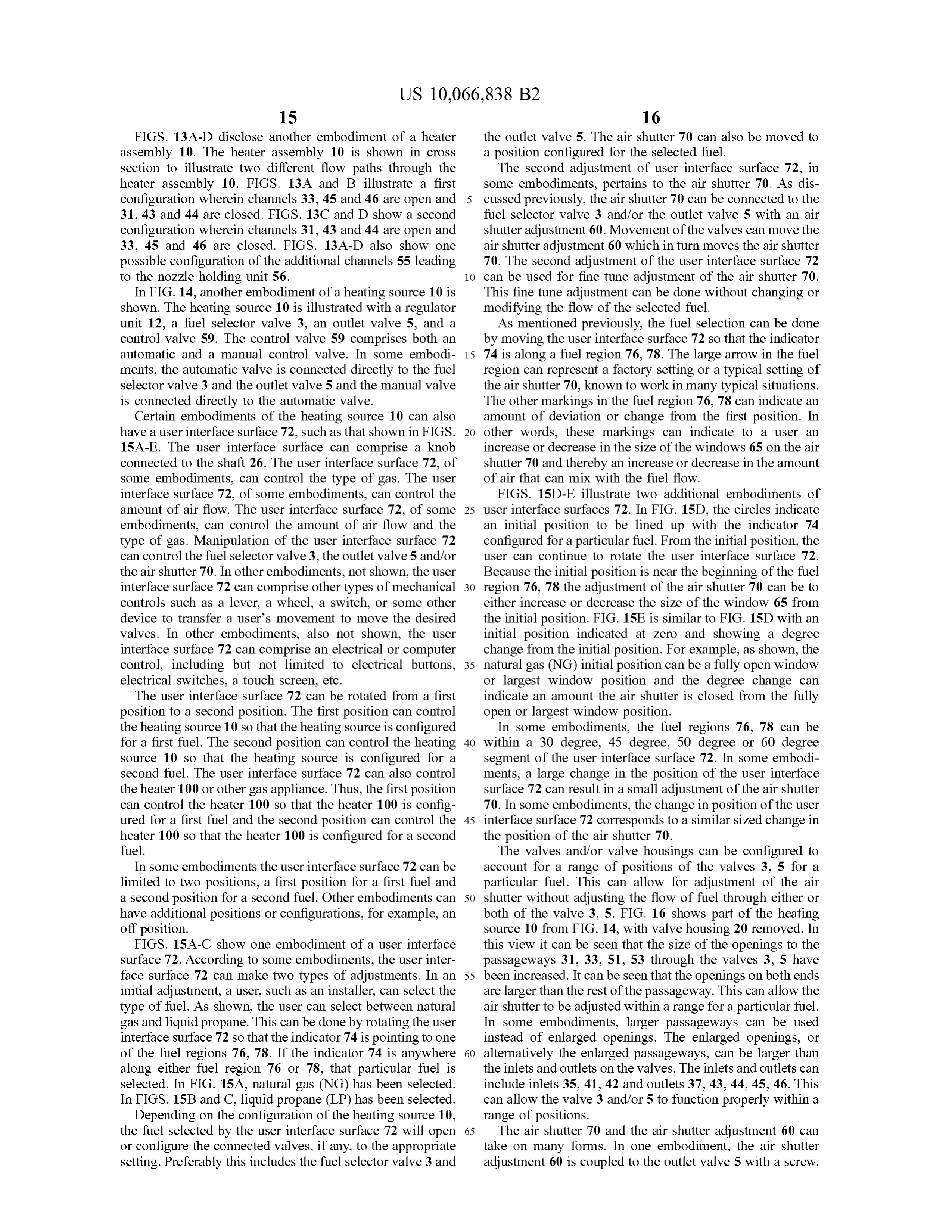
Page 58
In some embodiments , the outlet valve 5 further comprises As shown , the sealed chamber 90 is sealed to the outside a projection 80 which extends through the end cap 24 . The with the exception of the air intake 211 and the exhaust 212. projection 80 can comprise part of the air shutter adjustment Heated air does not flow from the sealed chamber to the 60. The air shutter 70 can attach to the outlet valve 5 through surroundings ; instead air , for example from in an interior the projection 80 . In some embodiments , the air shutter 70 5 room , can enter an inlet vent 214 . The air can pass through is coupled , fastened or otherwise connected to the projection channel 215 passing over the outside of the sealed chamber 80 . 90 and over the exhaust 212 . Heat is transferred to this air Now referring to FIGS . 17A - C , some embodiments of an which can then pass into the interior room through outlet air shutter 70 comprise two cylinders . The mixing compart- vent 216 .
ment 66 for mixing air with fuel can be inside the air shutter 10 As similarly discussed earlier with respect to the dual fuel 70 . The conduit 67 , here the internal cylinder, can be heater 100 , a dual fuel direct vent heater 210 is made up of stationary and the cover 63 , here the external cylinder , can various components . Many of the components are similar to move to change the size of the windows 65 . The shown those discussed in this regard or as discussed in other parts configuration is similar to that shown in FIGS. 12A and B . herein . One difference between the heater 100 and the direct The windows 65 are formed when the openings 84 or 86 line 15 vent heater 210 is in the use of a sealed combustion chamber up with the openings 82 . In FIGS. 12A - B the same openings 90 . The heater 100 has a burner 190 and combustion occurs are used for both fuels. In FIGS. 17A - C different openings within the housing 200 . A direct vent heater 210 has a burner are used for the different fuels. This configuration can allow 92 and a housing 218 , but inside of the housing 218 is a for more specific control over the air shutter 70 and the sealed combustion chamber 90 . The burner 92 is within the amount of air that can flow through the windows 65 depend - 20 sealed combustion chamber 90 , as is the oxygen depletion ing on the fuel. FIG . 17A illustrates the closed position and sensor (ODS ) 180, so that the combustion occurs within the 17B and C show a position for liquid propane and natural sealed combustion chamber 90 .
gas, respectively . Because the combustion chamber 90 is sealed it can be For example , in some embodiments, the opening used for difficult to access components within the chamber 90 . For one fuel is larger than the opening used for the other. The 25 this reason some components are within the chamber 90 but various embodiments and configurations can also have dif- many are not. In some embodiments, the components nec ferent numbers and/ or sizes of openings . For example , one e ssary for combustion are within the chamber 90 and others fuelmight use three openings where the other might use two. are outside.
These openings could be the same openings or different The schematic diagram in FIG . 19 shows some of the openings. In some embodiments , the openings are rectan - 30 components used for combustion within the sealed combus gular for one fuel and triangular for the other. In some tion chamber 90 , such as , the burner 92 , the air shutter 70 embodiments , one opening is equal to or greater than double and the ODS 180 . Other components not shown that may the size of the other opening . also be inside can include : a nozzle , and a thermostat or Different sized openings can be advantageous especially other temperature sensor. Also shown is a heating source 10 where different fuels require different amounts of air to 35 and other components 9 connected to the heating source 10 . produce the same sized flame. One fuel may require a small FIG . 20 is an embodiment of a direct vent heater 210 . It amount of air compared with another fuel. For this reason it can be seen a basket 201 can form part of the sealed chamber can be beneficial to use different sized openings . The open - 90 . The basket 201 can facilitate placement of some of the ings for the first fuel can be smaller and open up to a lesser component parts of the heater 210 within the sealed chamber extent or more gradually as compared to the openings for the 40 90, while others remain outside.
other fuel that requires more air . FIG . 21 shows an embodiment of a heating source 10 In some embodiments the cover 63 can attach to the within the housing 218 . As can be seen , pipes connected to projection 80 (FIG . 16 ) . This can allow for control of the air the outlets 45 and 46 pass into the sealed combustion shutter 70 by rotation of the valves such as by movement of chamber 90 through fittings 94 attached to and sealing the the user interface surface 72 as previously described . 45 holes or entry points in the wall 219 of the sealed combus FIGS. 18A and B illustrate another embodiment of an air tion chamber 90 . The flow of fuel through outlet 46 can be shutter 70 with two rotating cylinders. The air shutter 70 can directed to the burner and the flow of fuel through outlet 45 form two windows 65 on opposite sides of the air shutter 70 can be directed to the ODS . Outlets 44 and 43 , not shown , for each fuel selected . The conduit 67 has two sets of can also direct flow to the burner and ODS respectively in different sized triangular holes 84 , 86 and the cover 63 has 50 a similar manner as has been described previously . two rectangular holes 82 . The two rectangular holes 82 on Part of the heating source 10 can also pass into the sealed the cover 63 can be positioned to allow air flow through combustion chamber 90 through a fitting 94 . For example , either of the first or second sets of triangular holes 84 , 86 . the projection 80 (FIG . 16 ) can pass into the sealed com Further adjustment can then bemade to decrease or increase bustion chamber 90 to provide control of the air shutter 70 the size of the windows 65 , or the amount of the holes that 55 with the user interface surface 72 . The fitting 94 can be a overlap and allow air flow therethrough . separate fitting that allows the valve or pipe to pass into the Aspects of certain embodiments with use in a dual fuel sealed combustion chamber 90 in a sealed fashion . In some Sot toto direct vent heater 210 will now be described with respect embodiments the end cap 24 can comprise the fitting 94 ( for FIG . 19 . A direct vent heater 210 can have an air intake 211 example , FIGS . 7 - 9 , 16 ). For example , the end cap 24 can which passes through an outside wall 213 of a building . The 60 be inside the sealed combustion chamber 90 and the valve air intake 211 directs air into a sealed chamber 90 of the housing 20 can outside . The two parts can then be connected direct vent heater 210. The air can be mixed with a fuel in a sealed fashion around a wall 219 of the combustion through the air shutter 70 to then be combusted at a burner chamber 90 . This can both seal the valve housing 20 and seal 92. The direct vent heater 210 can have a log insert 217 to the hole through to the combustion chamber 90 . give the appearance of a natural wood burning fire . The 65 In some embodiments one or more of the fuel lines and exhaust gas can then exit the sealed chamber through an the air shutter control can pass into the sealed combustion exhaust 212 . chamber 90 through the same fitting 94 . For example , the
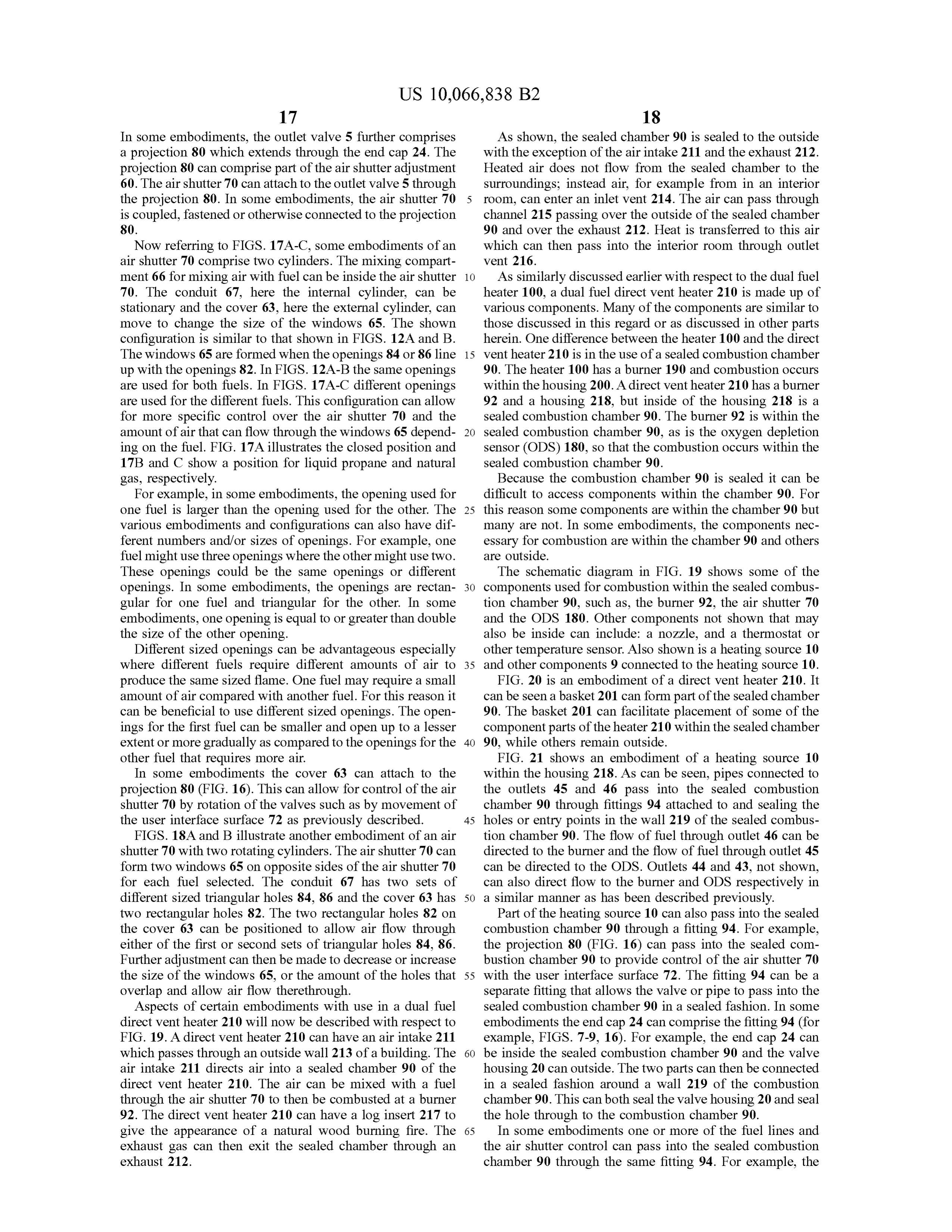
Page 59
heating source 10 shown in FIG . 11 can be connected to a chamber 90 through the same fitting 94 . This can benefi wall of the combustion chamber 90 such that the fuel cially reduce the number of fittings 94 . selector valve 3 and the outlet valve 5 are outside and the air The nozzle 96 can have many different configurations . shutter adjustment 60 and the nozzle holding unit 56 are FIG . 23 shows another embodiment of heating source 10 inside the sealed combustion chamber 90 . The additional 5 with a nozzle 96 . The cross -sectional view of FIG . 23A channels 55 directing fuel to the burner and the screw which shows the nozzle 96 configured for a first fuel. In some connects the air shutter adjustment to the outlet valve 5 can embodiments the first fuel is natural gas. The cross -sectional use the same fitting 94 to enter the sealed combustion view of FIG . 23B shows the nozzle 96 configured for a chamber 90 . second fuel. In some embodiments the second fuel is pro
These configurations can advantageously decrease the Referring to FIG . 23A , in some embodiments the nozzle number of fittings 94 required and the number of entry 96 can have a first chamber 533 and a second chamber 534 . points into the sealed combustion chamber 90 that require Each chamber can end in an orifice 97, 98 and each chamber fittings 94. can be configured for receiving a flow of fuel therethrough . FIG . 22A shows another embodiment of a heating source 15 As shown the second chamber 534 is substantially within 10 which provides further benefits . For example , the number the first chamber 533 . As also can be seen , orifice 98 of the and size of the fittings 94 are decreased . In the valve shown , second chamber 534 is within the first chamber 533 . a nozzle 96 has advantageously been combined with the In some embodiments , the second orifice 98 can be outlet valve 5 . The nozzle 96 simplifies the construction of positioned downstream of the first orifice 97 , as can be seen the heater 100 , direct vent heater 210 or other gas appliance . 20 in FIG . 24 . In addition the first orifice can be made up of a This is because the outlets 44 and 46 are eliminated . The number of holes 99 . The holes can surround the second outlets 44 and 46 in some embodiments, were connected to orifice. In some embodiments there can be more than one a separate nozzle , with each outlet 44 , 46 connected to a row of holes, such as two or three rows of holes surrounding channel configured to direct the fuel to an area of the nozzle the second orifice . Such a configuration can work to aerate configured for the particular fuel designed to flow through 25 the fuel to achieve more efficient combustion . In some that outlet and channel. embodiments, the nozzle can be configured such that one The two different positions of the outlet valve 5 now can fuel, such as propane, can travel through the second orifice also define two different channels 531 , 532 that each connect 98 and a second fuel, such as natural gas , can travel through to the nozzle 96 in a different way (FIGS. 22B - C ) . Channel the holes 99 of the first orifice 87 . In other embodiments , the 531 can be configured for a first fuel and direct the first fuel 30 nozzle can be configured such that one fuel, such as propane, from the inlet 42 into the nozzle 96 . The nozzle 96 can then can travel through the second orifice 98 and a second fuel, direct the first fuel through a first orifice 97 . The first orifice such as natural gas, can travel through both the holes 99 of can be configured for natural gas . The nozzle can also have the first orifice 87 and the second orifice 98 . Such a a second orifice 98 . The second orifice 98 can be configured configuration can beneficially produce quieter and more for liquid propane . 35 efficient combustion of fuel.
In the illustrated embodiment, the first and second orifices FIGS. 25A - B show how a heating source 10 with a nozzle 97, 98 can be different sizes. The second orifice 98 can be 96 connected to the outlet valve 5 and an air shutter 70 can smaller than the first orifice 97 . This can allow one fuel to function together with a basket 201 as part of the sealed use both orifices. For example, in some embodiments , a fuel combustion chamber 90 ( see FIG . 20 ). The fuel for com that uses the smaller of the two orifices can pass through the 40 bustion in the burner can pass through the nozzle and one larger orifice and then the smaller orifice . As another fitting 94 into the basket 201 of the sealed combustion example, a fuel that uses the smaller orifice can pass through chamber 90 . The air shutter control can pass through this the smaller orifice first and then pass through the other same fitting . Electrical wires (not shown ) from the ODS 180 orifice . The nozzle can be configured such that the fuel that can pass through the same fitting 94 as the pipes 95 leading needs the larger orifice can pass through the larger orifice 45 to the ODS . This configuration can reduce the number of and not the smaller orifice. fittings through to the sealed combustion chamber. This The nozzle 96 can have a first flow configuration or path configuration can also greatly simplify the control of the going through the nozzle 96 passing through both the first heating source 10 such that one adjustment to select the fuel and second orifices 97 , 98 and a second flow configuration and then possible minor adjustments to adjust the air shutter or path going through only one of the orifices . For example , 50 are all that is required . These adjustments can all be accom a flow of natural gas can flow through the first orifice 97 and plished with the same control feature , such as the knob 72 . not through the second orifice 98 . Referring now to FIGS . 26A and B , another embodiment After exiting the nozzle a fuel can pass into the mixing of a heating source 10 is shown . The heating source includes chamber 66 to be mixed with air as discussed previously. a selector valve 3 and an outlet valve 5 which are controlled The air shutter 70 can attach to the nozzle 96 so that it will 55 by a geared mechanism 11 . As shown, the geared mecha rotate with the nozzle 96 and can be adjusted as described nism 11 includes a driving gear 16 and two driven gears 18 , with respect to the user interface surface 72 . 19 , where one driven gear 18 controls the fuel selector valve In some embodiments, the nozzle 96 can be made integral 3 and one driven gear 19 controls the outlet valve 5 . The user with the fuel selector valve 3 , with or without the outlet interface surface 72 can be used to rotate the driving gear 16 . valve 5 .Making a selection with the fuel selector valve 3 by 60 This control of the driving gear 16 can be done directly , rotation or otherwise can determine the flow path through through other controls , or gears or in other ways. As can be the nozzle 96 . seen , the driving gear 16 can be on the same shaft 26 as the Also shown in FIG . 22A are the fittings 94 through which user interface surface 72 . Thus, the user interface surface 72 the nozzle 96 and ODS channels , connected to the outlets 43 can provide direct control of the rotation of the driving gear and 45 , pass into the sealed combustion chamber 90 . As the 65 16 .
nozzle 96 can make up part of a fuel line, the fuel line and The driven gears 18 , 19 can be on a shaft 27 . The shaft 27 the air shutter control can pass into the sealed combustion can have a threaded portion 29 that can engage a threaded
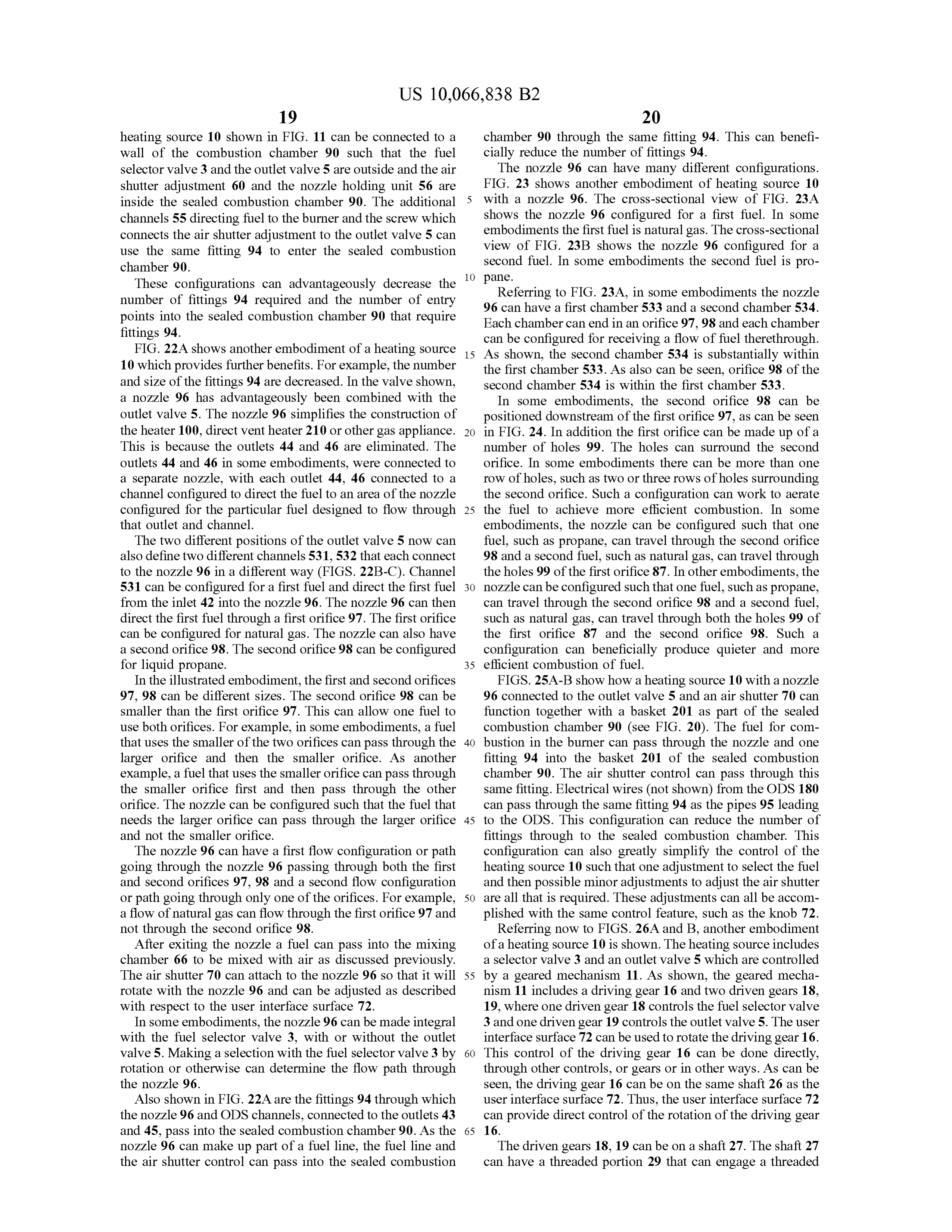
Page 60
channel 31 on the housing 20. This can allow the shaft 27 to shafts 26 , 27 . For example, with the pin closer to shaft 26 convert the rotational movement of the gear 18 , 19 into than to shaft 27 , a smallmovement in shaft 26 can translate linear movement which can be used to open and close into a larger movement in shaft 27 . With the pin farther away various valves . For example , each shaft can have a first valve from shaft 26 the opposite would be true . 32 and a second valve 34 . As shown in FIG . 26A , in one 5 In some embodiments , the actuator 47 can comprise a position the first valve 32 can be closed and the second valve metal spring. For example , a metal plate or wire can be 34 can be open . In a second position , shown in FIG . 26B , the shaped with bends as shown in FIG . 27B . The movement of first valve 32 can be open and the second valve 34 can be the shafts 26 and 27 can be configured such that shaft 26 closed . This can allow , for example , either a first fuel or a moves more than necessary to open or close the valves 32 , second fuel to flow into an inlet 35 and out the outlet 37 . This 10 34. The extra movement can cause the spring to flex , can also allow flow through the inlet 41 and out either of applying a force on the valve 32 , 34 and thereby holding the outlets 43 and 45 . valve more firmly in place .
In some embodiments, the user interface surface 72 can be As well as moving linearly , the user interface surface 72 held in a locked position with a spring. Pushing the user can also rotate. The rotating motion can be used to control interface surface 72 towards the housing 20 can unlock the 15 the outlet valve 5 . Looking to FIGS. 28 , 28A and 28B , it is user interface surface 72 and allow rotation thereof. After shown how the outlet valve 5 can control the flow , for pushing and rotating , the user interface surface 72 can example to the ODS, through the outlets 43 , 45 . Flow can assume a locked or unlocked position that is either closer to enter inlet 41 and travel through channel 51 . The position of or farther from the housing 20 in comparison to the prior the slotted valve 49 , as best seen in FIGS. 28A and B , can position . Alternatively , the user interface surface 72 can be 20 determine whether the flow travels from channel 51 to either configured such that rotating the shaft 26 can also linearly channel 50 or 52 . Referring now to the arrows indicating the advance the shaft 26 . flow path on FIG . 28 , it can be seen that channel 50 leads to The shaft 26 can also include a nozzle control 36 . The outlet 43 and channel 52 leads to outlet 45 . nozzle control 36 can control the position of a nozzle shaft FIG . 29 illustrates a cross - section of FIG . 27 with the 38 within a chamber 39 inside of the nozzle 96 . The nozzle 25 nozzle 96 in the second position . FIG . 30 shows the nozzle shaft can function in one of two different ways . In some 96 in a first position . It can be seen that the heating source embodiments , the nozzle shaft 38 can also include a cham - of FIG . 27 can have a nozzle similar to that described above ber 40 with an orifice 98 . In the first position ( FIG . 26A ), with respect to FIGS. 26A and B .
fuel can flow into the nozzle through chamber 39 and out In FIG . 31 , another embodiment of a heating source 10 is orifice 97 . Linear movement of the shaft 26 towards the 30 shown . The heating source 10 is illustrated with a regulator second position (FIG . 26B ) can adjust the position of the unit 12 , a fuel selector valve 3 , an outlet valve 5 , and a nozzle control 36 to and seal and close the chamber 39 . Fuel control valve 59 . The control valve 59 comprises both an can then flow through chamber 40 and out of both orifice 98 automatic and a manual control valve . In some embodi and then orifice 97 . In this way , the nozzle 96 can be adjusted ments , the automatic valve is connected directly to the fuel for use with different fuels . The nozzle 96 according to 35 selector valve 3 and the outlet valve 5 and the manual valve certain embodiments can include a spring to bias the nozzle is connected directly to the automatic valve . towards either of the first or second positions. Looking to FIG . 32 , another embodiment of a heating In other embodiments , the position of the nozzle shaft 38 source is illustrated . FIG . 32A shows schematically the can determine the amount of fluid that can flow out of the positions of the internal shaft 26 as controlled by the user exit orifice 97 of the nozzle 96 . For example , fuel can flow 40 interface surface 72 . The heating source 10 of FIG . 32 can through chamber 39 in both the first and second positions have three positions . It can have a closed position , a first and the position of the nozzle shaft 38 within the chamber o pen position and a second open position . The first open 39 with respect to the interior surface of the chamber 39 can position can correspond to a first fuel and the second open determine how much fluid can flow through the orifice 97 . position can correspond to a second fuel. FIGS. 33 - 35 , In the second position the nozzle shaft 38 can limit the 45 including the A - C subsets will now be described with amount of fuel that can reach the orifice 97 . This can have respect to these three different positions. the effect of essentially creating a smaller orifice within the FIGS. 33 , 34 , 35 are schematic and partial cross -sectional chamber 39 . views of the heating source of FIG . 32 in the three positions Turning now to FIG . 27, another embodiment of heating stated above . The user interface surface 72 can control the source 10 is shown . FIGS. 27A and B illustrate the heating 50 position of the shaft 26 which can move the heating source source in schematic partial cross -sections in first and second between the three positions. The shaft 26 can include various configurations, respectively . The heating source is similar in cutouts 61 to allow the shaft 26 to act as a cam . In some some respects to that shown in FIGS. 26A and B , except that embodiments , the actuators 47 can act as followers on the instead of controlling the valves 32 and 34 through a gearing cam . The actuator 47 together with pin 48 and spring 54 can mechanism , an actuator or linkage 47 is employed to control 55 force the actuator into contact with the shaft 26 . Thus, when the positions of valves. the actuator 47 engages the cutout 61 , the spring will force In some embodiments, the actuator 47 can be connected the actuator forward into contact with the smaller diameter to both shaft 26 and shaft 27 and can rotate about a pin 48 . region of the shaft . This will also cause the shaft 27 to move , Thus, linear movement of the shaft 26 in one direction can opening the valve 32 or 34 . The cutouts 61 can be configured cause shaft 27 to move in the other direction through the 60 such that in one position , both valves 32 , 34 are closed . The movement of the actuator 47 . In this way, the shaft 27 is able cutouts 61 can also be configured such that in other posi to move between the positions shown , opening and closing tions, one or both of the valves 32, 34 are open . As shown, the valves . In other embodiments an actuator or bar can be both valves are closed in FIG . 33 , one valve is open in FIG . used without a pin . Movement of the shaft 26 would cause 34 and the other valve is open in FIG . 35 . a corresponding movement in shaft 27 . 65 FIGS. 33A , 34A , 35A are cross -sectional views taken An actuator 47 used with a pin 48 can advantageously be along line A - A of the respective base FIG . 33 , 34 or 35 . used to scale the amount of movement between the two FIGS . 33B , 34B , 35B are cross -sectional views taken along
Page 61
line B - B of the respective base FIG . 33 , 34 or 35 . In the ment, figure, or description thereof for the purpose of series figures a valve 71 can be seen and in the B series streamlining the disclosure and aiding in the understanding figures a valve 73 is shown. The valves 71, 73 act as of one or more of the various inventive aspects. This method followers to the cam , i.e . shaft 26 and cutouts 61 . Thus the of disclosure , however, is not to be interpreted as reflecting valves 71, 73 remain closed in the cutout 61 and open when 5 an intention that any claim require more features than are contacting the normal section of the shaft 26 . As an example , expressly recited in that claim . Rather, as the following in FIG . 34A , valve 71 is open and in FIG . 34B , valve 73 is claims reflect, inventive aspects lie in a combination of closed . fewer than all features of any single foregoing disclosed FIGS. 33C , 34C , 35C are cross -sectional views taken embodiment. Thus, the claims following the Detailed along line C -C of the respective base FIG . 33 , 34 or 35 . As 10 Description are hereby expressly incorporated into this can be seen , the end of shaft 26 can have a channel 53 . Detailed Description , with each claim standing on its own as Rotating the shaft 26 can open or close the channel 53 to a separate embodiment.
inlet 42 , as well as to the additional channel 55 and the What is claimed is :
nozzle 96 . The position of channel 53 can determine if and 1. A dual fuel heating system comprising : how fuel can flow into the nozzle 96 . In FIG . 33C , the 15 a first pressure regulator to regulate a flow of a first fuel, channel 53 is closed to inlet 42 . In FIG . 34C , the channel 53 the first pressure regulator having a first inlet and a first is open to inlet 42 and directs the flow of fuel to both outlet;
chambers of the nozzle 533 and 534 . In this configuration , a second pressure regulator to regulate a flow of a second fuel can flow out of both orifices 97 , 98 . In FIG . 35C , the fuel different from the first fuel and at a higher pressure channel 53 is open to inlet 42 and directs the flow of fuel to 20 than the first fuel, the second pressure regulator having chamber 534 but blocks the flow of fuel to chamber 533 of a second inlet and a second outlet ; the nozzle 96 . In this configuration , fuel flows out of orifice a fuel selector valve having a first position configured to 98 . permit a flow of the first fuel from the first outlet of the Looking now to one set of figures , FIGS. 35 - 35C , it can first pressure regulator through the fuel selector valve be seen that in this configuration , valve 34 is open , as is 25 and to prevent a flow from the second outlet of the valve 73 and valves 32 and 71 are closed . Also , channel 53 second pressure regulator through the fuel selector is open to inlet 42 and configured to direct fuel to chamber valve and having a second position configured to 534 while blocking flow to chamber 533 . permit a flow of the second fuel from the second outlet The heating source 10 as described herein has many of the second pressure regulator through the fuel selec benefits . One of these benefits is its versatility . As shown and 30 tor valve and to prevent a flow from the first outlet of described the heating sources 10 can be used for many the first pressure regulator through the fuel selector different types of gas appliances. Manufacturing a basic valve ; and component that can be used in many different situations may a control valve configured to divide the flow from the fuel significantly reduce costs across the different product lines . selector valve of either the first fuel or the second fuel For example , a heating source 10 in one configuration can be 35 into two separate flows leaving the control valve and to used in a vent free heater 100 and in another configuration control an amount of flow in each of the two separate or in the same configuration can be used in a direct vent flows leaving the control valve , heater 210 . In both instances the heating source 10 can allow wherein the control valve comprises at least one of a the appliance to use one of either of two different fuels . The manual valve , a thermostat valve, an AC solenoid , and different fuels can also be at different pressures. a DC solenoid .
As a further example ,many of the same parts may be used 2 . The dual fuel heating system of claim 1 , wherein the to produce the heating source 10 shown in FIG . 11 as that first fuel comprises natural gas and the second fuel com shown in FIG . 22 . In some embodiments , the outer valve prises liquid propane .
body 20 shown in FIG . 11 can be used with the outlet valve 3 . The dual fuel heating system of claim 1, wherein the 5 and nozzle 96 shown in FIG . 22 . Caps 58 can be used to 45 dual fuel heating system comprises part of a heater, oven , close unnecessary outlets 44 and 46 . Thus, the heating dryer or boiler.
source 10 is a modular unit with many different uses and 4 . The dual fuel heating system of claim 1, wherein the possible configurations. As also described herein the heating first pressure regulator is configured to provide a pressure in source 10 can comprise a number of different components the range from about 3 inches of water column to about 6 that can connect directly to one another without the use of 50 inches of water column .
additional connecting pipes , with FIGS . 13A - D being but 5 . The dual fuel heating system of claim 4 , wherein the one example . second pressure regulator is configured to provide a pressure Reference throughout this specification to " one embodi- in the range from about 8 inches of water column to about ment” or “ an embodiment” means that a particular feature , 12 inches of water column.
structure or characteristic described in connection with the 55 6 . The dual fuel heating system of claim 1, further embodiment is included in at least one embodiment. Thus , comprising an outlet valve having a set of inlets and first and appearances of the phrases “ in one embodiment” or “ in an second sets of outlets wherein in a first position of the outlet embodiment” in various places throughout this specification valve flow is permitted from the control valve into the set of are not necessarily all referring to the same embodiment. inlets to the first set of outlets and in a second position of the Furthermore, the particular features , structures or character - 60 outlet valve flow is permitted into the set of inlets through istics of any embodiment described above may be combined the outlet valve to the second set of outlets.
in any suitable manner, as would be apparent to one of 7 . The dual fuel heating system of claim 6 , wherein the ordinary skill in the art from this disclosure, in one or more fuel selector valve and the outlet valve are coupled together embodiments . such that selecting the first position on fuel selector valve Similarly, it should be appreciated that in the above 65 also selects the first position on the outlet valve and selecting description of embodiments , various features of the inven - the second position on the fuel selector valve also selects the tions are sometimes grouped together in a single embodi second position on the outlet valve.
Page 62
8 . A dual fuel heating system comprising : also selects the first position on the outlet valve and selecting a regulator housing comprising: the second position on the fuel selector valve also selects the first and second inlets ; second position on the outlet valve .
first and second outlets ; 15 . A dual fuel heating system comprising: a first pressure regulator to regulate a flow of a first 5 a first pressure regulator to regulate a flow of a first fuel, fuel; and the first pressure regulator having a first inlet and a first a second pressure regulator to regulate a flow of a outlet;
second fuel different from the first fuel and at a a second pressure regulator to regulate a flow of a second higher pressure than the first fuel; fuel different from the first fuel and at a higher pressure wherein the regulator housing defining two separate 10 flow paths therethrough : than the first fuel, the second pressure regulator having a first flow path configured such that the first fuel a second inlet and a second outlet; enters the regulator housing through the first inlet, a fuel selector valve having a first position configured to then passes through the first pressure regulator permit a flow of the first fuel from the first outlet of the before exiting the regulator housing at the first 15 first pressure regulator through the fuel selector valve outlet; and and to prevent a flow from the second outlet of the a second flow path configured such that the second second pressure regulator through the fuel selector fuel enters the regulator housing through the sec valve and having a second position configured to ond inlet, then passes through the second pressure permit a flow of the second fuel from the second outlet regulator before exiting the regulator housing 20 of the second pressure regulator through the fuel selec through the second outlet; tor valve and to prevent a flow from the first outlet of a fuel selector valve having a first position configured to the first pressure regulator through the fuel selector permit a flow of the first fuel from the first outlet of the valve ; and first flow path through the fuel selector valve and to a control valve configured to divide the flow from the fuel prevent a flow from the second outlet of the second 25 selector valve of either the first fuel or the second fuel flow path therethrough and having a second position into two separate flows leaving the control valve and to configured to permit a flow of the second fuel from the control an amount of flow in each of the two separate second outlet of the second pressure regulator through flows leaving the control valve, the fuel selector valve and to prevent a flow from the wherein the first fuel comprises natural gas and the second first outlet of the first flow path therethrough , 30 fuel comprises liquid propane .
wherein the control valve comprises at least one of a 16 . The dual fuelheating system of claim 15 , wherein the manual valve , a thermostat valve, an AC solenoid , and control valve comprises at least one of a manual valve , a a DC solenoid .
9 . The dual fuel heating system of claim 8 , wherein the thermostat valve , an AC solenoid , and a DC solenoid . first fuel comprises natural gas and the second fuel com - 35 17 . The dual fuel heating system of claim 15 , wherein the prises liquid propane . first pressure regulator is configured to provide a pressure in 10 . The dual fuel heating system of claim 8 . wherein the the range from about 3 inches of water column to about 6 dual fuel heating system comprises part of a heater, oven , inches of water column .
dryer or boiler. 18 . The dual fuel heating system of claim 17 , wherein the 11. The dual fuel heating system of claim 8 , wherein the 40 second pressure regulator is configured to provide a pressure first pressure regulator is configured to provide a pressure in in the range from about 8 inches of water column to about the range from about 3 inches of water column to about 6 12 inches of water column.
inches of water column . 19 . The dual fuel heating system of claim 15 , further 12 . The dual fuel heating system of claim 8 , wherein the comprising an outlet valve having a set of inlets and first and second pressure regulator is configured to provide a pressure 45 second sets ofoutlets wherein in a first position of the outlet in the range from about 8 inches of water column to about valve flow is permitted from the control valve into the set of 12 inches of water column . inlets to the first set of outlets and in a second position of the 13 . The dual fuel heating system of claim 8 , further outlet valve flow is permitted into the set of inlets through comprising an outlet valve having a set of inlets and first and the outlet valve to the second set of outlets . second sets of outlets wherein in a first position of the outlet 50 20 . The
The dual dual fuel fuelheating system of claim 19 , wherein the valve flow is permitted from the control valve into the set of fuel20selector valve and the outlet valve are coupled together inlets to the first set of outlets and in a second position of the such that selecting the first position on fuel selector valve outlet valve flow is permitted into the set of inlets through also selects the first position on the outlet valve and selecting the outlet valve to the second set of outlets. the " second 14 . The dual fuelheating system of claim 13 , wherein the 55 second position on the fuel selector valve also selects the position on the outlet valve .
fuel selector valve and the outlet valve are coupled together such that selecting the first position on fuel selector valve * * * * *
Provenance
- Collection
- Cited prior art
- Original PDF
- patentimages.storage.googleapis.com →
- Filed
- 2015-09-18
- Pages
- 62
- Method
- pdftotext (the PDF's own text layer) + pdftoppm 300dpi page scans
- Source
- Google Patents bibliographic record
- Granted
- 2018-09-04
- Inventors
- David Deng
- Transcribed from
- patentimages.storage.googleapis.com →