patent · US5408957
Continuous combustible gas injection into conventionally fueled internal combustion engines
25 April 1995
Page 1 — bibliographic record
United States Patent (19) 11) Patent Number: 5,408,957 Crowley (45) Date of Patent: Apr. 25, 1995 54 CONTINUOUS COMBUSTIBLE GAS Primary Examiner-E. Rollins Cross NJECTION INTO CONVENTIONALLY Assistant Examiner-Erick Solis
FUELED INTERNAL COMBUSTION Attorney, Agent, or Firm-F. Eugene Davis, IV
ENGINES
(76) Inventor: Timothy J. Crowley, 1031 Post Rd., Liquefied petroleum gas (propane), natural gas, hydro Darien, Conn. 06820 gen gas, or the like, is continuously injected at substan 21) Appl. No.: 54,792 tially constant pressure into the air intake manifold, or air induction system, of a conventional internal combus 22) Filed: Apr. 28, 1993 tion engine, the engine being electronically, or mechani 51 int. Cl'................................................ FO2B 3/00 cally, controlled to adjust the air to liquid fuel mixture 52 U.S.C. ................................ 123/27 GE; 123/526 to a optimum value. The engine may use liquid gasoline, 58 Field of Search ............... 123/698,525,526, 527, methanol, diesel, or any other, primary fuel. When 123/575, 27 GE retrofitted to a conventional 2 or 4 stroke, spark or compression ignited engine, the gaseous fuel preferable (56) References Cited is supplied from a reservoir where it is stored in lique
fied or compressed form through an appropriate pres sure control valve to a pipe T installed in the crankcase 4,227,497 10/1980 Mathieson ........................... 123/525 ventilation pipe. The supply of gaseous fuel is con 4,369,751 1/1983 Batchelor et al. .................. 123/525 trolled by an ON-OFF solenoid valves which are only 4,450,821 5/1984 Venning et al. .................... 123/575 operated when the alternator or generator of the engine 4,541,397 9/1985 Young ................................. 123/525 is running and the engine has attained a predetermined 4,637,353 1/1987 Codrington ......................... 123/526 temperature. A thermostatic switch in series between 4,638,783 1/1987 Snyder ........... 123/27 GE the generator and the solenoid valves and located in the 4,641,625 2/1987 Smith .................................. 123/575 4,909,209 3/1990 Takahasi ... 123/27 GE lower radiator flow pipe may be employed for this 5,092,305 3/1992 King .................................... 123/575 purpose. The pressure of the gas supplied to the engine is adjusted at idle with the engine at normal tempera
FOREIGN PATENT DOCUMENTS ture. The pressure is set between pressures at which the 0179349 1/1982 Japan 8 ww 4 so a were as a & as 8ss ss ss. 123/525 engine runs rough and pollutes excessively. 0082556 5/1984 Japan ................................... 123/525 4259651 9/1992 Japan. 123/525 20 Claims, 5 Drawing Sheets
Page 2
Drawing sheet — no readable text.
Page 3
Drawing sheet — no readable text.
Page 4
Drawing sheet — no readable text.
Page 5
Drawing sheet — no readable text.
Page 6
Drawing sheet — no readable text.
Page 7
CONTINUOUS COMBUSTIBLE GAS INJECTION
In the retrofit applications, described in detail herein, the gaseous fuel such as propane, natural gas, hydrogen
INTO CONVENTIONALLY FUELEED INTERNAL or any other combustible gaseous fuel is injected into COMBUSTON ENGINES the engine's existing air induction or intake manifold system. The gaseous fuel is stored in liquid or com
TECHNICAL FIELD pressed form in a tank which may be installed at the rear This invention relates to continuous combustible gas of an automobile or behind the cab of a truck. The gas injection into conventionally fueled internal combus is supplied from the storage tank to an appropriate pres tion engines. More particularly, it relates to systems sure reducing regulator valve, then through a safety employing liquefied petroleum, compressed natural gas, 10 valve or valve which only allows the gas to pass if it is compressed hydrogen, or the like. The invention fur between a lower and an upper pressure limit, and then ther relates to internal combustion engines that are to a pair ofvalves solenoid operated valves. When the solenoid under automatic control, such as gasoline engines elec operated are opened, the gas is supplied at a substantially constant pressure to the intake manifold or tronically controlled in response to an exhaust oxygen 15 air sensor to adjust the air liquid fuel ratio, and to diesel gine.induction manifold of the internal combustion en Preferably in conventional automobiles, this is engines so governed or governed by conventional rota tional speed governors. achieved by employing a T-shaped pipefitting placed in the recirculating pipe for engine gases connected be
BACKGROUND ART tween the PCV valve and the intake manifold. The A number of systems have been proposed for utilizing 20 solenoid valves are located at either end of the gaseous gaseous and liquid fuels in internal combustion engines, fuel line, i.e., one at the engine and one at the gaseous but many devices have involved complex changes to line whentothefuel tank prevent escape of gaseous fuel from the fuel engine is off.
the engine with complex controls and switches which are not user friendly. One device disclosed in U.S. Pat. running and hasfuel
The gaseous is supplied only when the engine is achieved a minimum temperature. In
No. 4,068,639, suggests the use of a gaseous fuel reser 25 add-on systems to existing automobiles and trucks, this voir and manual switching controls. U.S. Pat. No. is accomplished by connecting an electric line from the 3,753,424 injects a gaseous fuel only at load conditions generator of the engine and not at a constant pressure as in the ated switch connectedthrough or alternator to the athermostatically oper solenoid valves. The present invention. U.S. Pat. Nos. 3,718,000, 2,381,304, 30 switch operates the solenoids when the thermostatic and 3,659,574 use either a gaseous fuel or a liquid fuel switch operates at a predetermined temperature, which but never both at the same time. .
may be, for example, 125 F. The thermostatically
The system disclosed in U.S. Pat. No. 4,373,493 uti ated switch may be conveniently located in the lower oper lizes a gaseous fuel injected into a liquid fuel carburetor. coolant line connected to the radiator. The switch is It varies the amount of gaseous fuel flow with engine 35 conventional and may be the same type of switch as load and injects an additional amount of atmospheric air utilized mixed into the gaseous fuel port. This system requires unit or toto control supply information to an electronic control an electric cooling fan in a conven shutting off the supply of liquid fuel at idle and requires tional engine.
the engine to operate at idle on only the gaseous fuel, unlike the present invention which only substitutes a anInoxygen engines provided with electronic control modules, sensor is employed which senses the oxygen portion of the liquid fuel with gaseous fuel at idle. in the exhaust gases and adjusts the air fuel mixture Consequently if an air conditioner or other intermit utilized by the engine. This is usually accomplished by tent devices such as fans, radios, lights, etc., are oper primarily controlling the ated at idle the engine may stall or the idle has to be set engine; the amount of airamount of fuel supplied to the higher than normal to prevent stalling, thus decreasing 45 der during each stroke being controlledtoprimarily being supplied each cylin
fuel efficiency. the throttle. This means that the negative pressure in the The system disclosed in U.S. Pat. No. 4,373,493 being open to the atmosphere permits leakage of gaseous fuel air intake manifold does not vary greatly during normal driving. For most engines it is approximately 18" Hg. I to the atmosphere. supply, according to my invention, a gaseous fuel at DISCLOSURE OF THE INVENTION 50 approximately a positive 18 pounds per square inch to the air intake manifold. Thus, at any given engine oper
The present invention may be applied to two or four ating condition the O2 sensor will reduce the amount of stroke or rotary internal combustion engines or turbines primary fuel supplied or increase the air intake to adjust that utilize a primary fuel. It may be conveniently re the oxygen content of the exhaust to a predetermined trofitted to any internal combustion engine having an 55 limit. These control units in a gasoline engine are usu air induction vacuum system into which the gaseous ally set to an air fuel mixture ratio of 14.5-14.7. Ideally, fuel may be introduced at a low constant pressure. using my system, this ratio may be adjusted to 15.1-18.5 In OEM applications, the gaseous fuel may be intro to provide a leaner burn and a cleaner exhaust than duced at a higher pressure into the primary fuel line. would otherwise be achieved. However, even if the Mixing means may be employed to thoroughly mix the preset air to fuel ratio is not adjusted, substantially de fuels before injection into the combustion chamber. creased hydrocarbon, carbon monoxide, and nitrous This means could, for example, be an ultrasonic mixer oxide emissions are achieved in using my system. Fur either externally powered or using an ultrasonic whis thermore, the engine efficiency is increased. tle. The secondary gaseous fuel is utilized as a supple In the newer diesel systems employing electronic ment to assist in the vaporization of the primary fuel so control, the same operating conditions may be as to enhance the wave of combustion. The invention achieved. In conventional diesel engines liquid fuel reduces pollutant emissions and increases engine operat delivery is controlled by a governor. The vehicle's ing efficiency. accelerator is connected to the governor set point,
Page 8
which sets the engine's maximum operating speed. constructions and methods hereinafter described. The Since the introduction of gaseous fuel into the air induc scope of the invention will be indicated in the claims. tion system will automatically tend to speed up the engine, the governor will reduce the liquid fuel flow to BRIEF DESCRIPTION OF THE DRAWINGS the injectors. I have found that the addition of a con For a fuller understanding of the nature and objects stant flow of gaseous fuel to a diesel obtains a significant of the invention, reference should be had to the follow reduction in engine clatter which is related to ignition ing detailed description, taken in connection With the lag. The worse the ignition lag, the greater the chatter. accompanying drawings, in which:
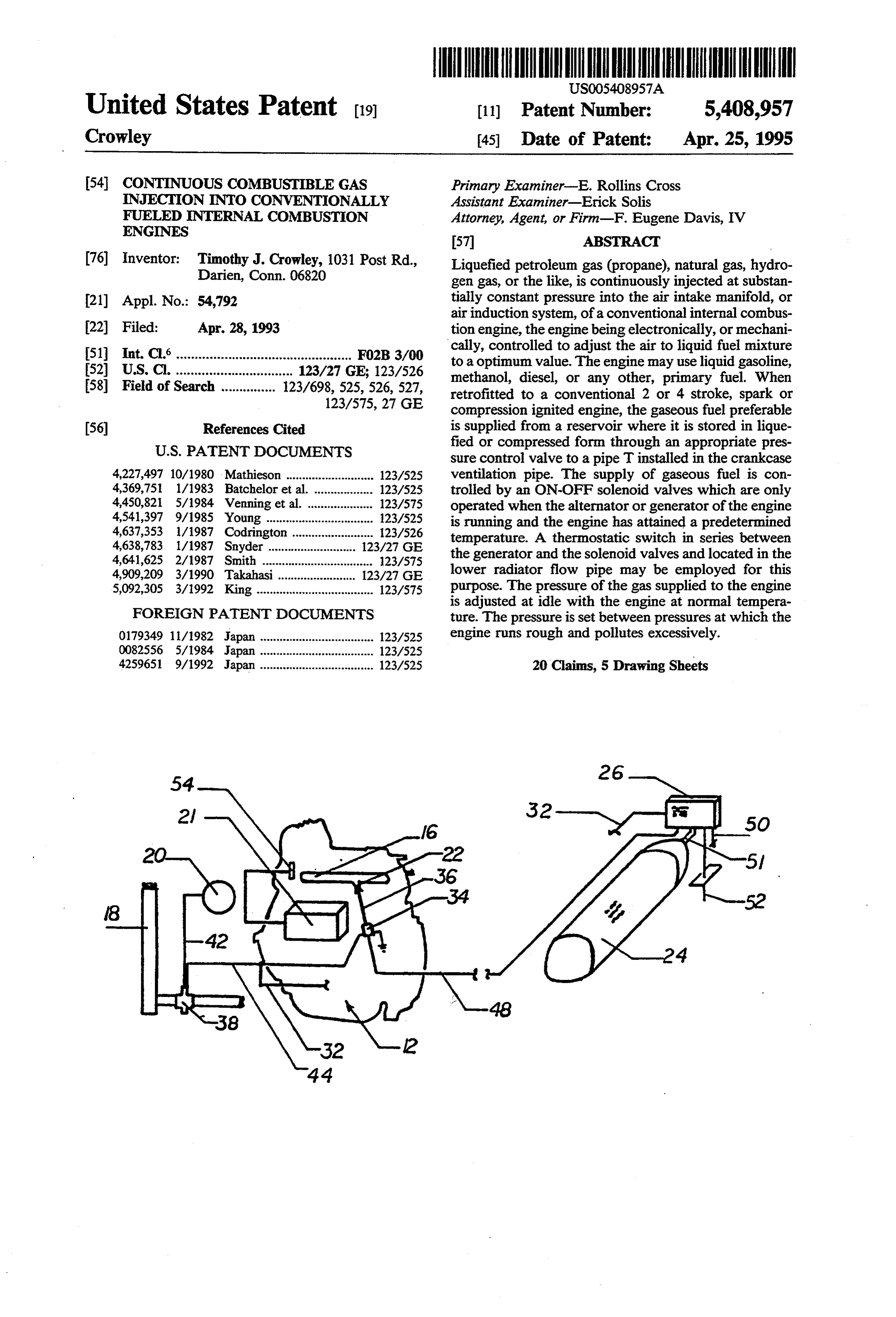
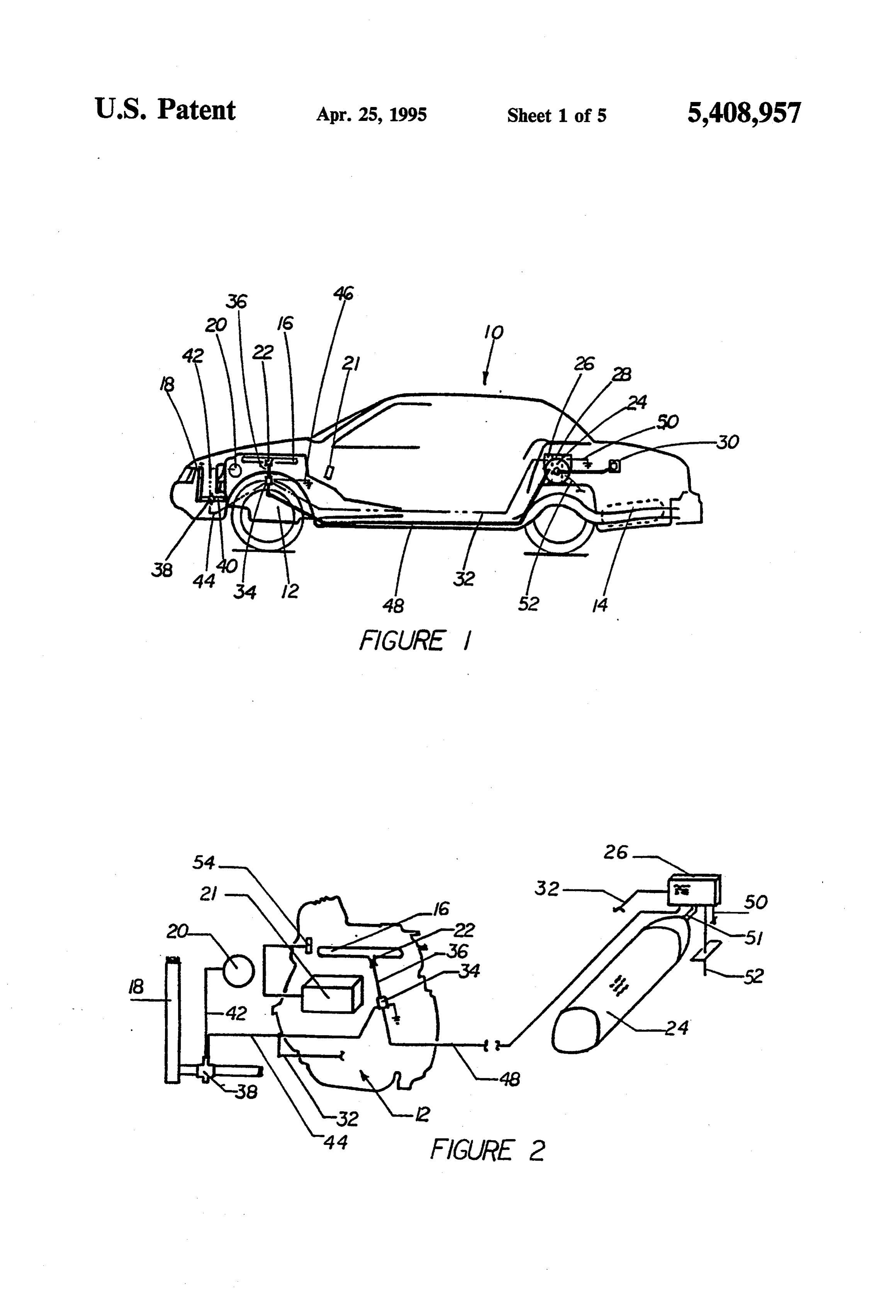
Thus the present invention injects a gaseous fuel at a FIG. 1 is a diagrammatic side view of the invention constant pressure directly into the engine's air induction 10 retrofitted in a conventional automobile; system, air intake manifold, conventional fuel line, or FIG. 2 is a diagrammatic view of the invention directly into the combustion chamber, and allows the shown in FIG. 1;
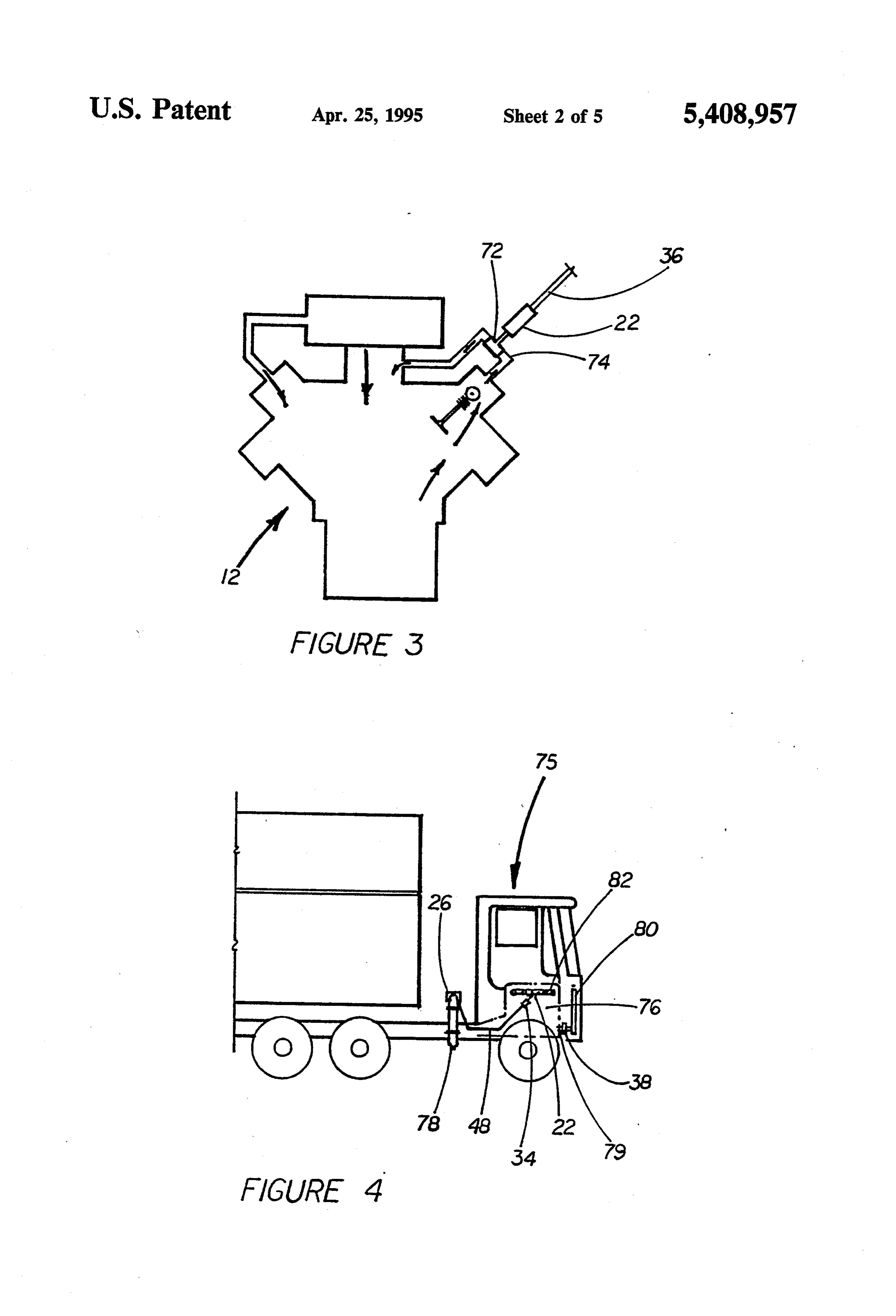
engine's own management system to adjust the flow of FIG. 3 is a diagrammatic view of a conventional liquid fuel at load and idle, as well as optimize the liquid engine showing how the gaseous fuel may be supplied fuel flow for the best air to fuel mixture. 15 thereto;
When my invention is installed in an existing automo FIG. 4 is a diagrammatic view of the invention retrof bile, for example, having a gasoline engine, I adjust the itted on a diesel tractor trailer;
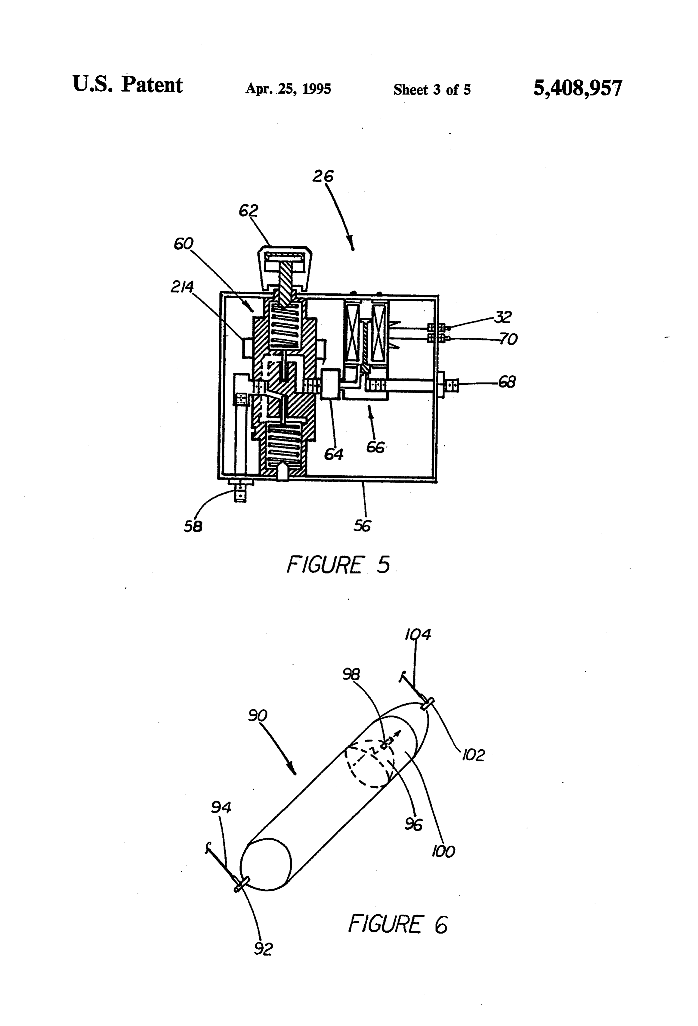
pressure regulator to supply gaseous fuel at idle with FIG. 5 is a cross-sectional view of the control unit of the engine at its normal operating temperature. If the the invention shown in FIG. 1;
pressure is too low the engine will idle in its normal 20 FIG. 6 is a diagrammatic view of the LP gas storage rough manner. If the pressure is too high it will also run vessel shown in FIG. 1 with an internal expansion rough. In both cases the deleterious exhaust emissions valve;
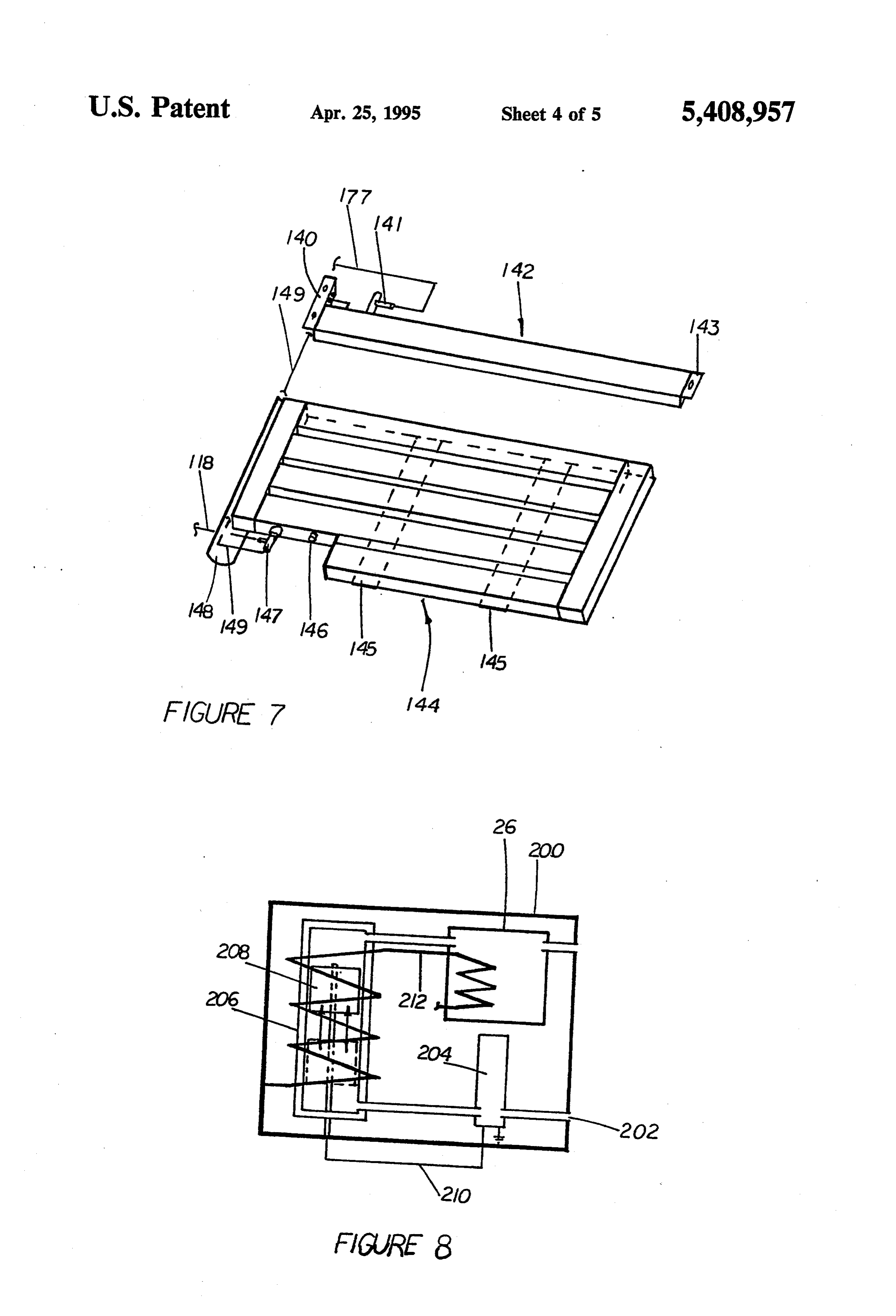
will be excessive. For an inlet orifice of 0.025/inch FIG. 7 is a diagrammatic view of an alternative flat diameter I find a pressure between 15 and 19 pounds per liquified petroleum gas storage vessel with a separate square inch to be appropriate, usually about 18 pounds 25 expansion vessel for application underneath a vehicle; per square inch. At this flow rate (approximately 4.8 FIG. 8 is a diagrammatic view of a gasifier mecha liters perminute), the engine runs smoother and quieter, nism and control module that may be used in the inven at idle, than when supplied with only gasoline. This tion;
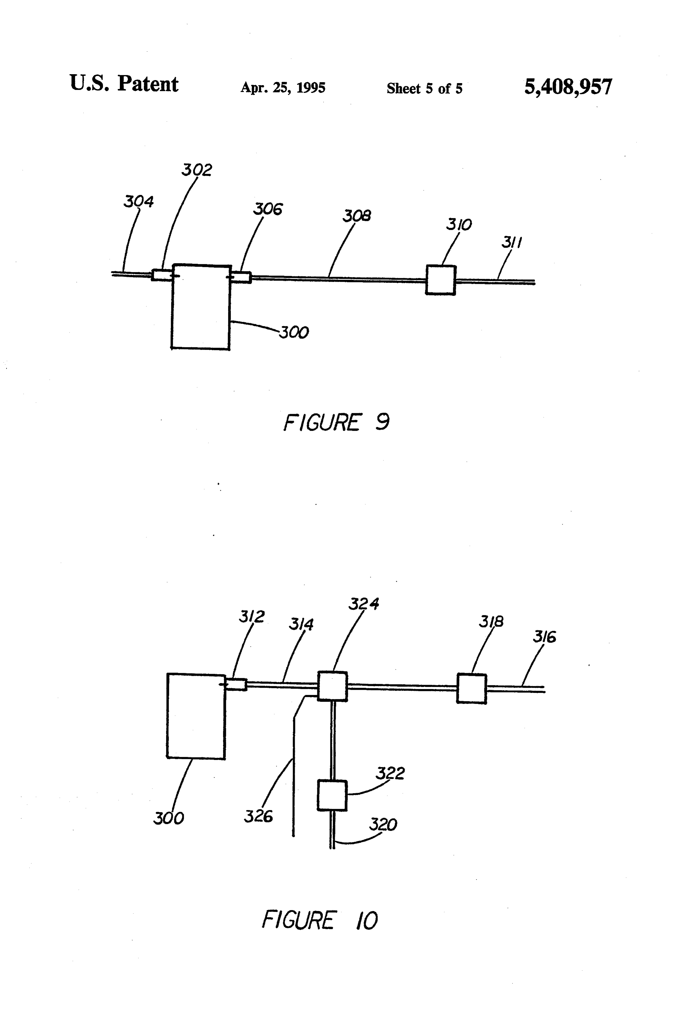
means that the engine is burning the fuel supplied to it FIG. 9 is a diagram of an alternative embodiment of more efficiently. 30 my invention showing the gaseous fuel directly injected When installed in a diesel vehicle, smoother opera into a combustion chamber; and, tion (less chatter) at idle at a specific pressure (i.e. flow FIG. 10 is a diagram of another alternative embodi rate) is also achieved. This again indicates increased fuel ment of my invention showing the gaseous fuel being efficiency. mixed with the liquid fuel and directly injected into a 35 combustion chamber using a single injector.
OBJECTS OF THE INVENTION
The same reference characters refer to the same ele
It is therefore an object of the invention to provide ments throughout the several views of the drawings. improved gas injection into liquid fueled internal com bustion engines. BEST MODE FOR CARRYING OUT THE Another object of the invention is to provide such a INVENTION system operating at substantially constant pressure. Now referring to FIG. 1, there is shown a conven Yet another object of the invention is to provide such tional automobile generally indicated at 10 having an a system operating under substantially continuous flow engine 12 and an engine fuel storage tank 14. The engine conditions. is supplied with an air intake manifold 16, radiator 18, Still another object of the invention is to provide such 45 alternator 20, and electronic control module 21. a system only operating when the engine is operating According to the invention, I provide a secondary and has attained a predetermined minimum tempera gaseous fuel tank 24 and control module 26 held down ture. by strap 28. The tank 24 is provided with a gaseous fuel A further object of the invention is to provide such a fill connector and line generally indicated at 30. Gase system that may be added to an existing internal com 50 ous fuel is supplied via gaseous fuel pipe 48 to a solenoid bustion engine, with or without adjustment of its con operated valve 34 and then via gaseous fuel pipe 36 to trol system. orifice 22 into the engine intake manifold 16. Another object of the invention is to provide a flat The control module 26 contains controls for control tank for storing gaseous fuel. ling the supply and pressure of the gaseous fuel in the Yet another object of the invention is to provide a 55 gaseous fuel line 48 and gaseous fuel is only supplied gasifier for a system of the above character. through line 36 and orifice 22 to the intake manifold 16 A still further object of the invention is to increase when the engine is turned on and has reached a prede fuel efficiency in internal combustion engines. termined temperature. This accomplished by placing a A yet further object of the invention is to decrease thermostatic switch 38 in the lower coolant line 40 deleterious emissions from internal combustion engines. between the radiator 18 and the engine 12. The thermo Other objects of the invention will in part be obvious static switch 38 is connected in series between the alter and will in part appear hereinafter. nator 20 via electric lines 42 and 44 to the solenoid The invention accordingly comprises the features of control valve 34. The thermostatic switch 38 is set to construction, elements and arrangement of parts, arti close at a predetermined temperature; for example, 125 cles of manufacture possessing the features, properties 65 F., thus gaseous fuel will be fed through orifice 22 by and relation of elements and a method comprising one opening the solenoid valve 34 only when the engine is or more steps and the relationship of such steps to the running and has reached this normal operating tempera others, all of which will be exemplified in the articles, ture. The circuit between the alternator and the thermo
Page 9
static switch 38 is completed by a ground generally engine is at its operating temperature and at idle with all indicated at 46. The tank 24 is provided with an excess auxiliary equipment turned off, for the smoothest run pressure overflow pipe and outlet, generally indicated ning operation.
at 52, directed as required by the gaseous fuel being This range may be 15 to approximately 18.5 pounds used. per square inch. Under idling conditions the gaseous Now referring to FIG. 2, the liquid fuel air ratio is fuel flow rate is approximately 4.8 liters per minute. under control of the electronic module 21 and depends The systems of FIGS. 1-5 may use liquified petro upon the signal received from the oxygen sensor 54 leum or compressed natural gas. The storage tanks 24 which is located in the exhaust manifold (not shown). and 78 and regulator valve 60 being appropriately Now referring to FIG. 5, the control unit is generally O chosen for the gaseous fuel employed. Other gaseous indicated at 26. It comprises a housing 56. A gas input fuels such as hydrogen may also be employed. fitting 58 is connected via appropriate tubing (not Now referring to FIG. 6, a special LP gas cylinder 90 shown) to the gaseous fuel storage tank 24 (see FIGS. 1 according to my invention is supplied with the usual and 2) and is there supplied to a conventional regulator two-way fill and feed valve 92 connected to gaseous valve 60 provided with pressure control knob 62. The 15 fuel line 94. Gaseous fuel line 94 is connected to a fill gaseous fuel is then fed from the regulator valve 60 mechanism 30, such as illustrated in FIG. 1, and also to through a safety valve 64 to the solenoid actuated valve intake fitting 58 and regulator 60 of FIG. 5. In a conven 66 and passes out of the unit 26through fitting 68 which tional LP gas cylinder either valve 92 or another valve is connected to the gaseous fuel 48 (see FIGS. 1 and 2). would release gaseous fuel to the atmosphere if the The solenoid control valve 66 is connected to ground 20 pressure in the tank 90 exceeded a predetermined limit. at terminal 70 and to electrical line 32 which in turn is In order to recover some of the gaseous fuel that would connected to electrical line 44 (see FIG. 1), and thus to otherwise be lost, I provide the cylinder 90 with a hemi the thermostatic switch 38. spherical shaped internal baffle 96 and a high pressure By employing two solenoid valves, one 66 at the relief valve 98. This forms another chamber 100 within control unit 26, and another 34 adjacent to where the 25 the cylinder 90 to which gaseous fuel which passes gaseous fuel is injected into the automobile engine (see through relief valve 98 may be stored and supplied FIGS. 1 and 2), I automatically close off the gaseous through valve 102 to another fuel line 104 which is also fuel line 48 when gaseous fuel is not being supplied to connected to fitting 58 to the control box 26 (FIG. 5). If the engine 12 and thus assure that no gaseous fuel es the pressure within the additional storage area 100 ex capes from line 36 which occurs in some of the systems 30 ceeds a predetermined limit, and gaseous fuel is not in the prior art, where the gaseous fuel is supplied flowing in fuel line 104, valve 102 will release gaseous through a jet partially open to the atmosphere. fuel to the atmosphere when an excessive pressure is The safety valve 64 prevents gaseous fuel from pass reached in the conventional manner.
ing from the regulator 60 to the solenoid operated valve However, by providing the expansion chamber 100, 66 if the pressure of the gaseous fuel is too low or too 35 the gaseous fuel that is stored therein before the valve high, thus insuring that the gaseous fuel is supplied to 102 opens is saved for use in the system. the engine 12 within predetermined pressure limits. Reference is now made to FIG. 7 which shows an When the system according to my invention is in LPG storage vessel generally indicated at 144 which stalled on a conventional automobile as indicated in can be used in the applications shown in FIGS. 1 FIG. 1, 2, and 5, I allow the engine 12 to come to oper through 5. LPG liquid gaseous fuel is filled through fuel ating temperature and then, while the engine is idling fill line 118 through a two-way valve 147 into vessel and all accessory equipment turned off, I adjust the 144, liquid or gaseous LPG from vessel 144 is fed back regulator valve 60 by turning the knob 62 until the through two-way valve 147 through fuel line 118 when engine runs smoother, but I do not allow the pressure to demanded by an external apparatus such as the system go so high as the engine again becomes rough running. 45 control module 26 (see FIGS. 1 and 5). As gas in storage Thus, I adjust the regulator valve 60 by means of the vessel 144 expands it is relieved through valve 147 into control knob 62 for smoothest running at idle. This fuel line 149 over to storage vessel 142. Gaseous fuel appears to occur when the gaseous fuel is supplying from storage vessel 142 is fed through valve 141 into approximately 20% of the fuel requirements of the en fuel line 177 to an external apparatus such as system gine 12 and for conventional gasoline automobile en 50 control module 26. Should high pressure gas build up in gine this pressure is about 18 pounds per square inch. vessel 142 and not be allowed to flow through valve 141 Now referring to FIG. 3, according to my invention, into fuel feed line 177 to an external apparatus, such the gaseous fuel line 36 is connected through orifice 22 would be the case if system control module 26 were to a T pipe connector 72 which I locate in the gasoline inoperative, or some other device inactive, high pres vapor recirculation pipe 74 of the engine 12. 55 sure gas would exit valve 141 to atmosphere via stan Now referring to FIG. 4 wherein there is shown a dard external relief mechanisms of valve 141. Should truck generally indicated at 75, having a diesel engine high pressure gas build up in vessel 144 and not be generally indicated at 76, the retrofit gaseous supply allowed to pass through valve 147, it will vent through unit again comprises a tank 78, a control unit 26, gase relief port 146 to the atmosphere. Vessel 144 is held in ous fuel line 48 supplied to solenoid valve 34, the opera place by brackets 145 attached to vessel 144 with tion of which is controlled by a thermostatic switch 38 curved impact bar 148 installed forward of vessel 144. installed in the lower coolant conduit 79 to the radiator Relief vessel 142 is held in place by brackets 140 and 143 80. When the engine is running and at its operating fixed to vessel 142.
temperature, gaseous fuel is supplied from the tank 78 Now referring to FIG. 8, when extremely cold oper through the control unit 26 and through solenoid valve 65 ating conditions are encountered, the system may be 34 to the orifice 22, where it is injected into the air provided with a gaseous fuel volatilizer in housing 200. induction system 82 of the diesel engine 76. Again, I Gaseous fuel is supplied by input fitting 202 to a sole regulate the pressure of gaseous fuel supplied while the noid operated valve 204. The gaseous fuel may, in ex
Page 10
tremely cold conditions, be liquid when passing ments of the scope of the invention which as a matter of through solenoid 204 and thus it is supplied to a cham language might be said to fall therebetween. ber 206 arranged vertically as shown. Gaseous fuel in Having described my invention, what I claim as new liquid form will rise in chamber 206 to a level which and desire to secure by Letters Patent is: will raise a float switch generally indicated at 208, 1. Apparatus for supplying a gaseous fuel supplement which is in series with the control line 210 to the sole to an internal combustion engine primarily supplied noid valve 204. Thus, when the liquified gaseous fuel with liquid fuel and oxygen when the supply of liquid reaches a predetermined level in chamber 206, the flow fuel is controlled by a sensor sensing an engine operat will be cut off. Meanwhile the chamber 206 is heated by ing condition, said apparatus comprising: an electric heater generally indicated at 212 which vola 10 A first valve means having only a fully opened and a tilizes the fuel which may then be supplied to the system fully closed position and a gaseous fuel supply inlet control module 26 which may also be heated by the and a gaseous fuel outlet connected to supply gase electric heater 212. ous fuel therethrough at substantially constant Also, when operating in extremely cold conditions, pressure to said engine; and, an electric heating element 214 may be mounted on the 15 B means for fully opening said first valve means to expansion valve 60 of the control unit 26 (see FIG. 5). supply gaseous fuel at a substantially constant rate Those skilled in the art will understand that the elec whenever said engine is running at or above nor tric heaters 212 and 214 are thermostatically controlled mal idle.
and that they could be replaced by using a hot coolant 2. Apparatus as defined in claim 1 wherein said en line from the radiator of the vehicle on which the sys gine operating condition is the speed of the engine. tem is mounted. 3. Apparatus as defined in claim 1 wherein said en Now referring to FIG. 9, the gaseous fuel could be gine operating condition is the amount of oxygen in the directly injected into a cylinder 300 to which liquid fuel engine's exhaust.
is supplied by injector 302 supplied by liquid fuel online 4. Apparatus as defined in claim 1 wherein said en 304, by employing a second injector 306 supplied with 25 gine comprises an exhaust oxygen sensor and said means gaseous fuel 308. It will be understood that in order to for fully opening said valve is responsive to said oxygen Supply the gaseous fuel at a high enough pressure it sensor sensing a predetermined quantity of oxygen. might be necessary to employ a gaseous fuel pump 310. 5. Apparatus as defined in claim 1 wherein said en However, this is less necessary when the gaseous fuel is gine is under control of an engine control computer and compressed natural gas. Another way of injecting gase said means for fully opening said valve is responsive to ous fuel directly into a cylinder 300 is to use a single a signal from said engine control computer indicating injector 312 to which a mixture of liquid and gaseous that said engine is not in a cold start condition to cause fuel is supplied on line 314. The liquid fuel is supplied said valve to open.
via line 316 to the liquid fuel pump 318. The gaseous 35 6. Apparatus as defined in claim 5 wherein said valve fuel is supplied on line 320 to a gaseous fuel pump 322, remains fully open until said engine is turned off. if required, and then to an appropriate mixer 324. Mixer 7. Apparatus as defined in claim 1 wherein said en 324 could be an appropriately formed labyrinthian mix gine comprises an intake manifold; and, ing chamber, an ultrasonic whistle, or an energy sup C conduit means for connecting said outlet to said plied ultrasonic or mechanical mixer supplied with elec intake manifold.
tric energy as indicated on electric line 326. 8. Apparatus as defined in claim 1 wherein said en In both embodiments illustrated in FIGS. 9 and 10, gine comprises an air intake induction line; and, the gaseous fuel is supplied at constant pressure to input C conduit means for connecting said outlet to said air lines 311 and 320 after passing through a control unit 26 intake induction line.
(see FIG. 5), and a nearby solenoid valve 34 (see FIGS. 45 9. Apparatus as defined in claim 1; and, 1 and 2). C means for sensing when said engine has reached When installed by a manufacturer, rather than con predetermined operating temperature, said means necting the solenoid valves 34 and 66 (FIGS. 1 and 5) to supplying a signal to said valve opening means to the thermostatic switch 38 and the alternator 20, the fully open said valve.
electric line 44 may be energized from the electronic 50 10. Apparatus as defined in claim 1 wherein the con control module 21. Thus, the solenoid valves 34 and 66 stant pressure at which said gaseous fuel is supplied to may be caused to open to supply gaseous fuel when the said engine is preset during engine idling at normal oxygen sensor 54 (FIG. 2) senses a predetermined engine operating temperature to minimize engine noise. amount of oxygen in the exhaust or when the engine is 11. Apparatus as defined in claim 10 wherein said not in a cold start condition. 55 gaseous fuel supplies about 20% of the energy to said It will thus be seen that the objects set forth above engine when idling at normal operating temperature. among those made apparent from the preceding de 12. Apparatus as defined in claim 1; and, Scription are efficiently attained and, since certain C a gaseous fuel supply tank; changes may be made in carrying out the above meth D a second valve means adjacent said fuel supply ods, and the described articles, and in the constructions 60 tank having only a fully opened and a fully closed set forth without departing from the scope of the inven position and a gaseous fuel supply inlet connected tion, it is intended that all matter contained in the above to said tank and a gaseous fuel outlet connected to description (or shown in the accompanying drawings) supply gaseous fuel therethrough and responsive to shall be interpreted as illustrative and not in a limiting said opening means as said first valve; and, SeSe. 65 E a gaseous fuel supply line from said outlet of said It is also to be understood that the following claims second valve to said inlet of said first valve, are intended to cover all of the generic and specific whereby said line is closed at each end when said features of the invention herein described, and all state engine is not running.
Page 11
13. Apparatus as defined in claim 1 wherein said en controlled by an engine speed governor said method gine comprises a liquid fuel supply line; and, comprising supplying a substantially constant steady C conduit means for connecting said outlet to said flow of gaseous fuel independent of engine load from a liquid fuel supply line. separate gaseous fuel reservoir at a preset pressure and 14. Apparatus as defined in claim 13; and, feeding the gaseous fuel through an orifice to the air D mixing means for mixing gaseous fuel and liquid supply to the engine whenever the engine is running at fuel in said liquid fuel supply line. or above normal idle.
15. Apparatus as defined in claim 1; and, 19. A method for utilizing both gaseous and liquid C means for injecting said gaseous fuel directly into a fuels in an internal combustion engine utilizing a pri combustion chamber of said engine. O mary fuel wherein the primary fuel induction quantity is 16. A method for utilizing both gaseous and liquid controlled by a separate means and adjusted when the fuels in an internal combustion engine utilizing a pri engine senses the richness of the fuel mixture, said mary fuel wherein the primary fuel induction quantity is method comprising supplying a substantially constant controlled by a separate means and adjusted when the steady flow of gaseous fuel to the engine independent of engine senses the richness of the fuel mixture, said 15 engine load from a separate gaseous fuel reservoir at a method comprising supplying a substantially constant preset pressure.
steady flow of gaseous fuel independent of engine load 20. A method for utilizing both gaseous and liquid from a separate gaseous fuel reservoir at a preset pres fuels in an internal combustion engine utilizing a pri sure and feeding the gaseous fuel through an orifice to mary fuel wherein the primary fuel induction quantity is the air supply to the engine. 20 controlled by an engine speed governor, said method 17. The method defined in claim 16 wherein said comprising supplying a substantially constant steady gaseous fuel is only supplied when the engine reaches its flow of gaseous fuel to the engine independent of engine operating temperature. load from a separate gaseous fuel reservoir at a preset 18. A method for utilizing both gaseous and liquid pressure whenever the engine is running at or above fuels in an internal combustion engine utilizing a pri 25 normal idle.
mary fuel wherein the primary fuel induction quantity is : k sk s: k
Provenance
- Collection
- Cited prior art
- Original PDF
- patentimages.storage.googleapis.com →
- Filed
- 1993-04-28
- Pages
- 11
- Method
- pdftotext (the PDF's own text layer) + pdftoppm 300dpi page scans
- Source
- Google Patents bibliographic record
- Granted
- 1995-04-25
- Inventors
- Timothy J. Crowley
- Transcribed from
- patentimages.storage.googleapis.com →