patent · US5359968
Hydrogen gas supply system for hydrogen engine
1 November 1994
Page 1 — bibliographic record
United States Patent 19 11 Patent Number: 5,359,968 Shiraishi et al. 45) Date of Patent: Nov. 1, 1994 54 HYDROGEN GAS SUPPLY SYSTEM FOR 5,271,359 12/1993 Teramoto et al........... 123/DIG. 12 HYDROGEN ENGINE FOREIGN PATENT DOCUMENTS 75) Inventors: Noriaki Shiraishi; Yoshio Mizushima; 0252862 11/1986 Japan .......................... 123/DIG. 12 Kenji Takamuku; Masaki Kadokura, 62-279264 12/1987 Japan.
all of Hiroshima, Japan 63-246458 10/1988 Japan .
73 Assignee: Mazda Motor Corporation, 0037159 2/1990 Japan .......................... 123/DIG. 12 Hiroshima, Japan Primary Examiner-E. Rollins Cross 21 Appl. No.: 96,819 Assistant Examiner-Erick Solis Attorney, Agent, or Firm-Keck, Mahin & Cate (22) Filed: Jul. 29, 1993 57 ABSTRACT 30) Foreign Application Priority Data
A hydrogen gas supply system, having metal hydride
Jul. 29, 1992 JP Japan .................................. 4-202522 alloy tanks in which hydrogen at a specific pressure is (51 Int. Cl. .............................................. FO2B 43/08 released within a specified range of temperatures and 52 U.S. C. ................................ 123/3; 123/DIG. 12 supplied to a hydrogen engine, is accompanied by a 58) Field of Search ................... 123/DIG. 12, 3, 575, coolant circulation system in which the engine and 123/41.31 tanks are connected in parallel, for circulating a coolant 56) References Cited through the engine and the tanks. The system executes temperature regulation of the coolant to the tank by
4,214,699 7/1980 Buchner et al. ............ 123/DIG. 12 coolant delivered from the engine when the coolant 4,253,428 3/1981 Billings et al............... 123/DIG. 12 from the engine is at above the specified temperature 4,385,726 5/1983 Bernauer et al. ........... 123/DIG. 12 range.
5,082,048 1/1992 Iwaki et al. ................. 123/DIG. 12 12 Claims, 8 Drawing Sheets
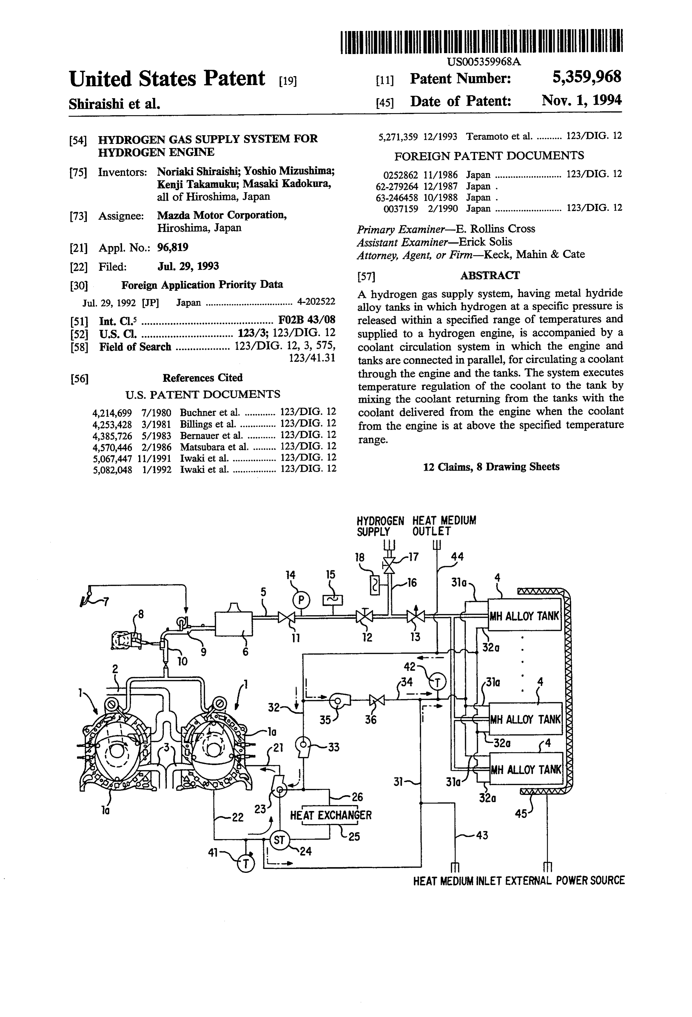
HYDROGEN HEAT MEDUM
SUPPLY OUTLET
C MH ALOY TANK
eMH ALOY TANK
HEAT MEDIUM INLET EXTERNAL POWERSOURCE
Page 2
Drawing sheet — no readable text.
Page 3
Drawing sheet — no readable text.
Page 4
Drawing sheet — no readable text.
Page 5
Drawing sheet — no readable text.
Page 6
Drawing sheet — no readable text.
Page 7
Drawing sheet — no readable text.
Page 8
Drawing sheet — no readable text.
Page 9
Drawing sheet — no readable text.
Page 10
After a wait to allow engine operation to stabilize after
HYDROGEN GAS SUPPLY SYSTEM FOR the switchover of tanks, vehicle drive is initiated. HYDROGEN ENGINE However, in vehicles equipped with two types of metal hydride-alloy tanks for startup and running as
BACKGROUND OF THE INVENTION 5 described above, since the temperature of the coolant is 1. Field of the Invention raised by warming after hydrogen engine startup and The present invention relates to a hydrogen gas sup the vehicle does not run until the switchover of tanks ply device for hydrogen engines. has been made to the mobile tank from the startup tank, 2. Description of Related Art starting reliability decreases. Moreover, hydrogen re The development of the hydrogen engine as a form of 10 leased by the startup tank during warming is not applied non-polluting engine system has been progressing in to running, lowering fuel efficiency with respect to actual mileage.
recent years. In order to supply hydrogen fuel to this Although the startup metal hydride alloy described type of engine, metal hydrides (which are hereafter referred to as metal hydride alloys), contained in tanks 15 above could conceivably be stored in high-pressure (which are hereafter referred to as metal hydride alloy imately 10 capable containers atm. and of withstanding pressures of approx above, and hydrogen from these tanks) which are mounted on vehicles, have been em containers could be supplied to the hydrogen engine ployed to occlude or storage and release hydrogen. during running as well, drawbacks are encountered Such hydrogen engine configurations or systems are when mounting such high-pressure containers in vehi known from, for example, Japanese Unexamined Patent cles in the form of various additional elements required Publications Nos. 62-279264 and 63-246458. to ensure safety, thus complicating the configuration However, to effect release of occluded hydrogen in and precluding weight reduction.
metal hydride alloy tanks at a specific predetermined pressure, i.e. the optimal release pressure, 4-10 atm., for SUMMARY OF THE INVENTION example, for injection into the hydrogen engine, the 25 It is a primary object of the present invention to pro metal hydride-alloy tanks must be maintained at a ten vide a hydrogen gas supply device for hydrogen en perature corresponding to the optimal release pressure. gines that not only ensures reliable startup of the hydro To this end, in the hydrogen engine system described in gen engine and raises fuel efficiency, but permits the Japanese Unexamined Patent Publication No. simplification of its own design and reduction in its own 63-246458, hot water is produced by heat exchange 30 weight.
with exhaust gas from the hydrogen engine and circu It is another object of the present invention to pro lated through the metal hydride alloy tanks as a heat vide a hydrogen gas supply device for hydrogen en medium. gines that is capable of more stably supplying hydrogen On the other hand, coolant is conventionally circu to the hydrogen engine.
lated through an engine cylinder block to prevent the 35 The foregoing objects of the present invention are engine from being overheated. The coolant is generally achieved by providing a hydrogen gas supply system heated to temperatures exceeding 90° C. in the course of having tanks, each of which contains a hydride storage this circulation. Accordingly, a configuration in which alloy and in each of which hydrogen at a pressure suit coolant is circulated as a heat medium through the able for engine operation is released within a specified metal hydride alloy tank permits a simpler overall de range of temperatures and supplied to a hydrogen en sign than the abovementioned configuration in which gine. The hydrogen gas supply system cooperates with hot water is generated by the aid of exhaust gas. a looped coolant circulation system which connects the In a system in which engine coolant is circulated engine and tanks in parallel so as to circulate a coolant through the metal hydride alloy tank as a heat medium, through them. This coolant circulation system is ac a metal hydride tank, which contains a metal hydride 45 companied by a temperature regulation means, posi alloy which releases hydrogen at the optimal release tioned therein in parallel with both engine and tank, pressure in the temperature range of, for example, which forces the coolant returning from the tanks to 60-90 C., is mounted on a vehicle. mix with the coolant delivered from the engine when During engine startup, even when coolant water of the coolant from the engine is at above the specified approximately the same temperature as ordinary tem 50 range of temperatures so as to regulate the temperature perature of atmospheric or ambient air, i.e., between 15 of the coolant circulating through the tanks. C. and 25 C., is circulated, release of hydrogen at the Specifically, the temperature regulation means con optimal release pressure is not achieved with the metal prises a bypass line and a regulation valve through hydride alloy tank. Thus, an extra metal hydride alloy which the coolant from the tanks flows to bypass the tank, which in turn is used for startup, has convention 55 engine and enters the coolant from the engine. This ally been mounted on the vehicle. That is, this extra regulation valve is intermittently controlled to open and metal hydride alloy tank (which is hereafter referred to closed such that the greater the temperature of the as a startup tank for simplicity) contains a metal hydride coolant from the engine is, the longer the period of the alloy having temperature-pressure properties making it regulation valve remains open. Further, the hydrogen possible to achieve optimal release pressure at an ambi gas supply system is accompanied by a heat exchange ent air temperature of approximately 10 C. The hydro means including a heat exchanger, such as a radiator gen engine is started with hydrogen generated in the positioned in parallel with both engine and tanks, startup metal hydride alloy tank. When the coolant through which the coolant circulating through the en exceeds, for example, approximately 60 C. due to sub gine is forced to flow to the engine when the tempera sequent warming, the supply of hydrogen to the hydro 65 ture of the coolant exceeds a predetermined tempera gen engine is switched over from the startup hydride ture so as to cool the coolant from the engine by trans alloy tank to the metal hydride alloy tank (which is fer of heat to the atmospheric air. When the coolant is hereafter referred to as the mobile tank for simplicity). forced to flow through the heat exchanger, it is also
Page 11
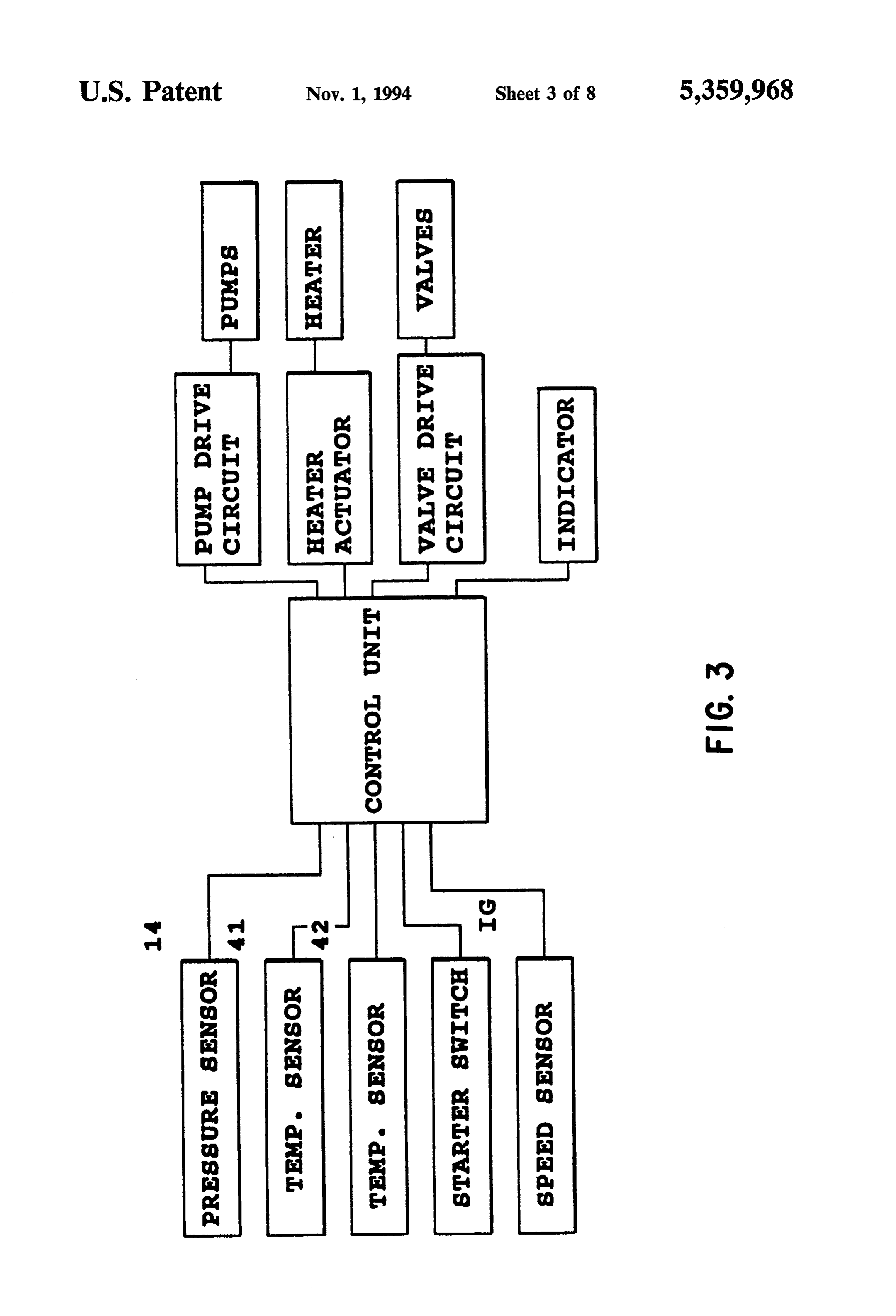
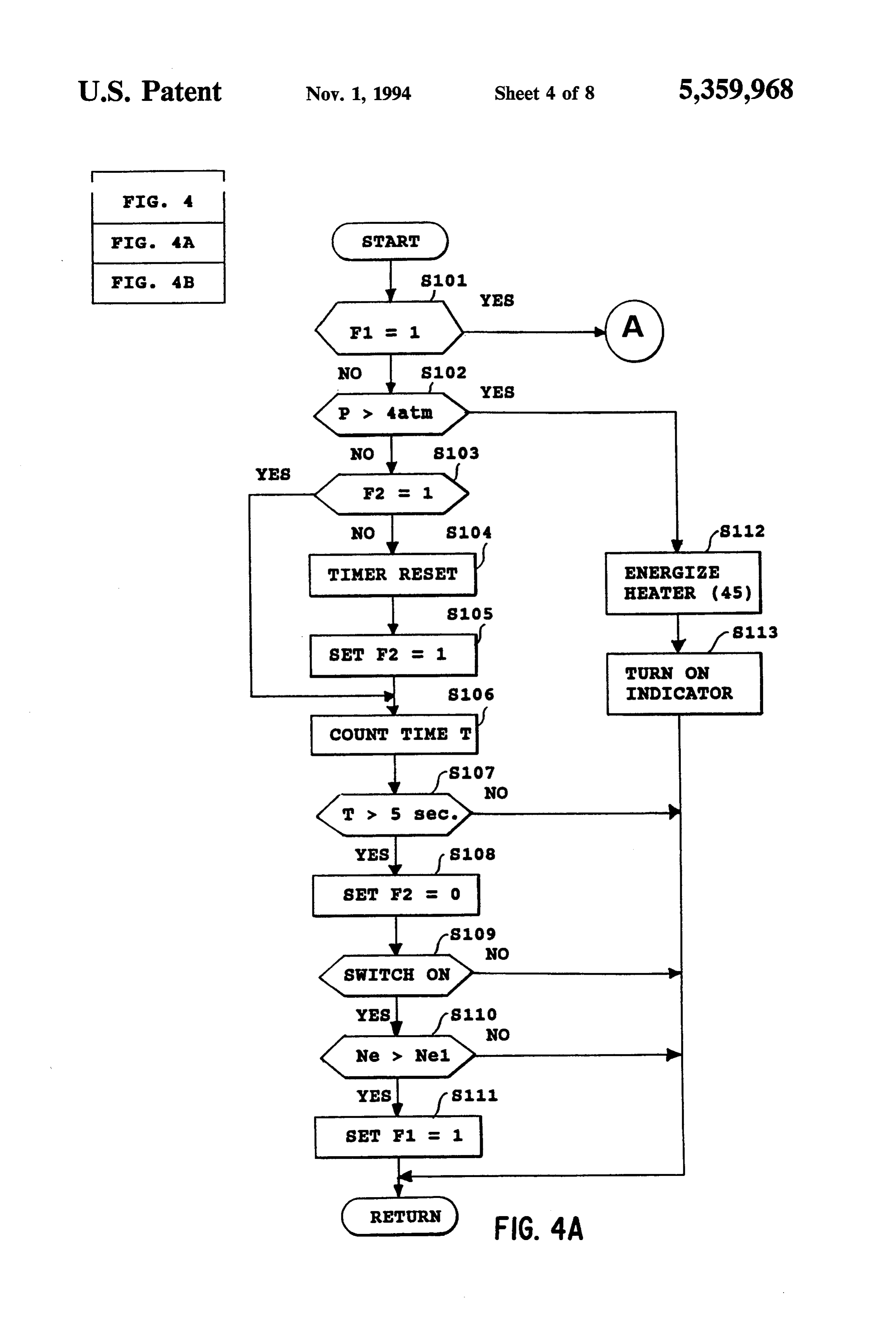
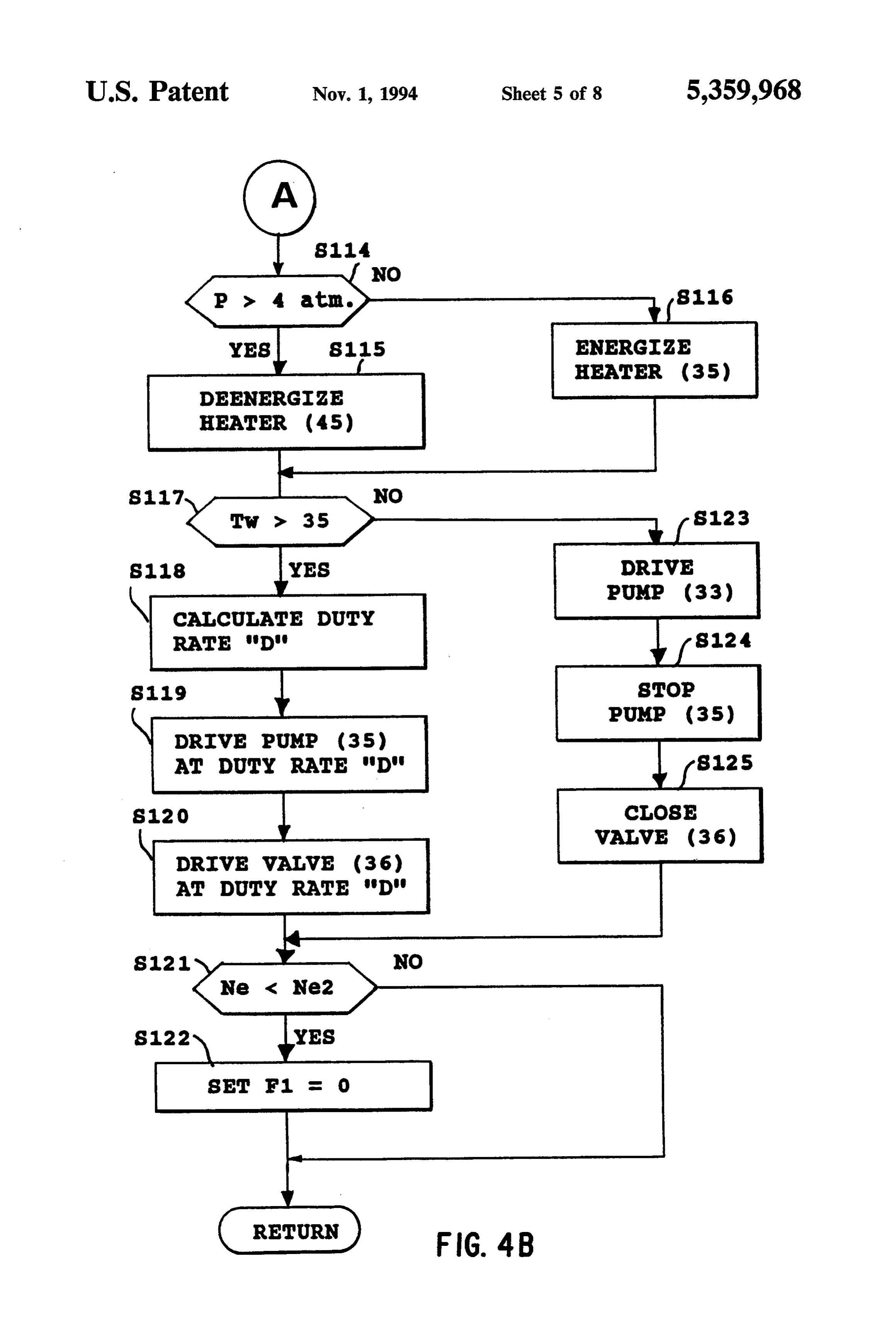
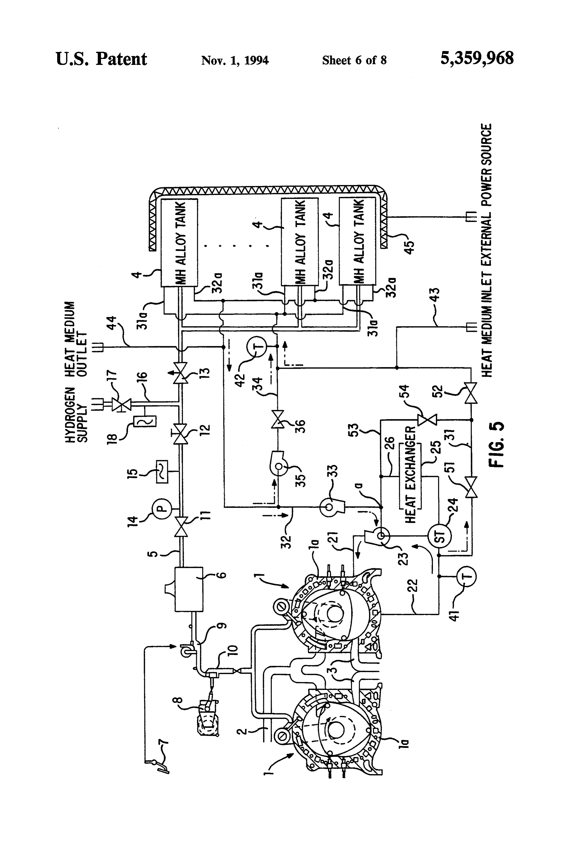
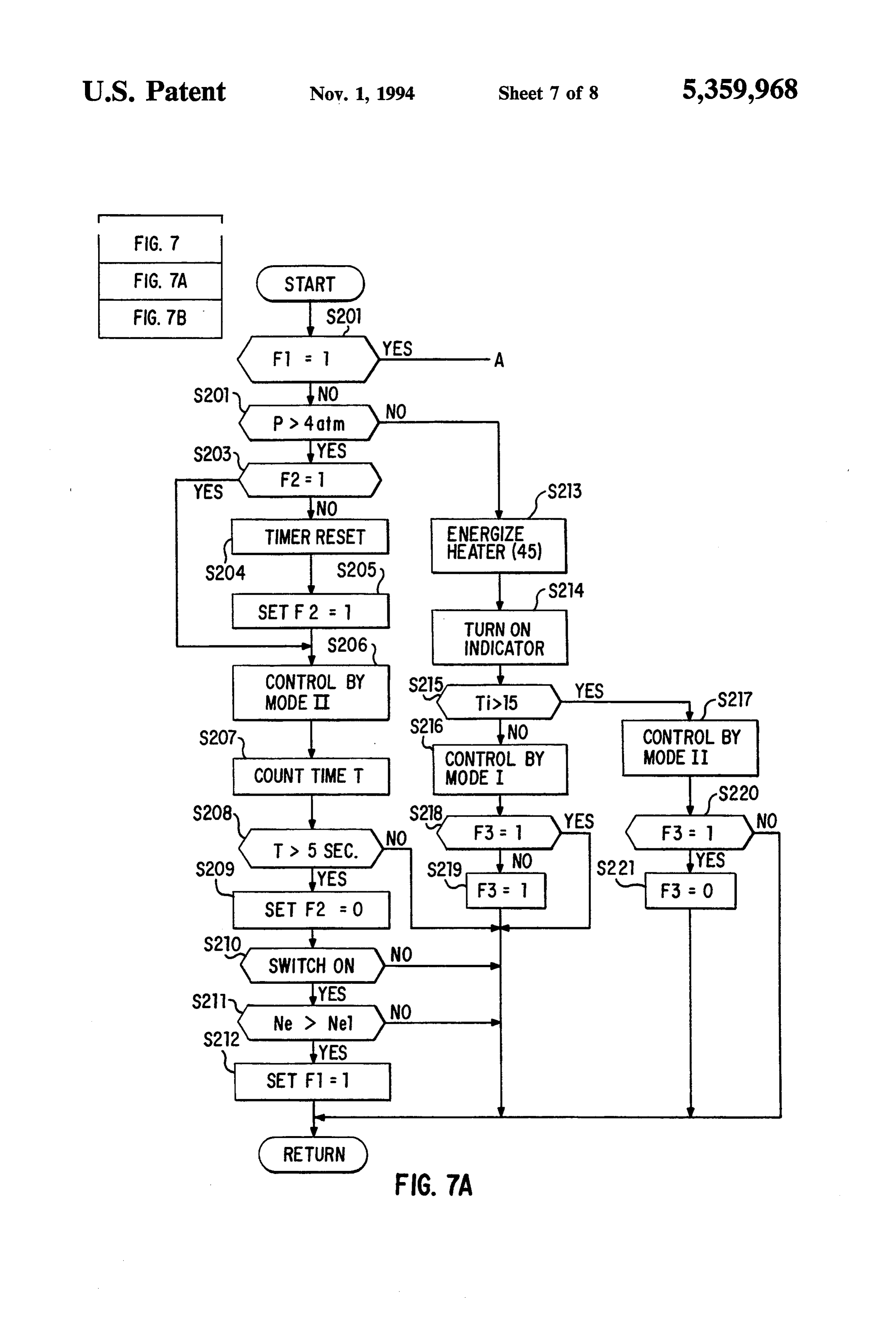
directed to the tanks in place of the coolant directly FIG. 3 is a block diagram showing how a control unit from the engine. controls the hydrogen gas supply system; Since hydrogen released in the hydrogen storage FIGS. 4A and 4B are a flow chart illustrating a con alloy tanks is at the specific pressure (which is referred trol sequence for the system shown in FIG. 1; to as the optimal release pressure) required for engine 5 FIG. 5 is a schematic view of a hydrogen gas supply operation and is within a specific temperature range system in accordance with another preferred embodi close to ordinary temperatures, it can be used to start ment of the present invention;
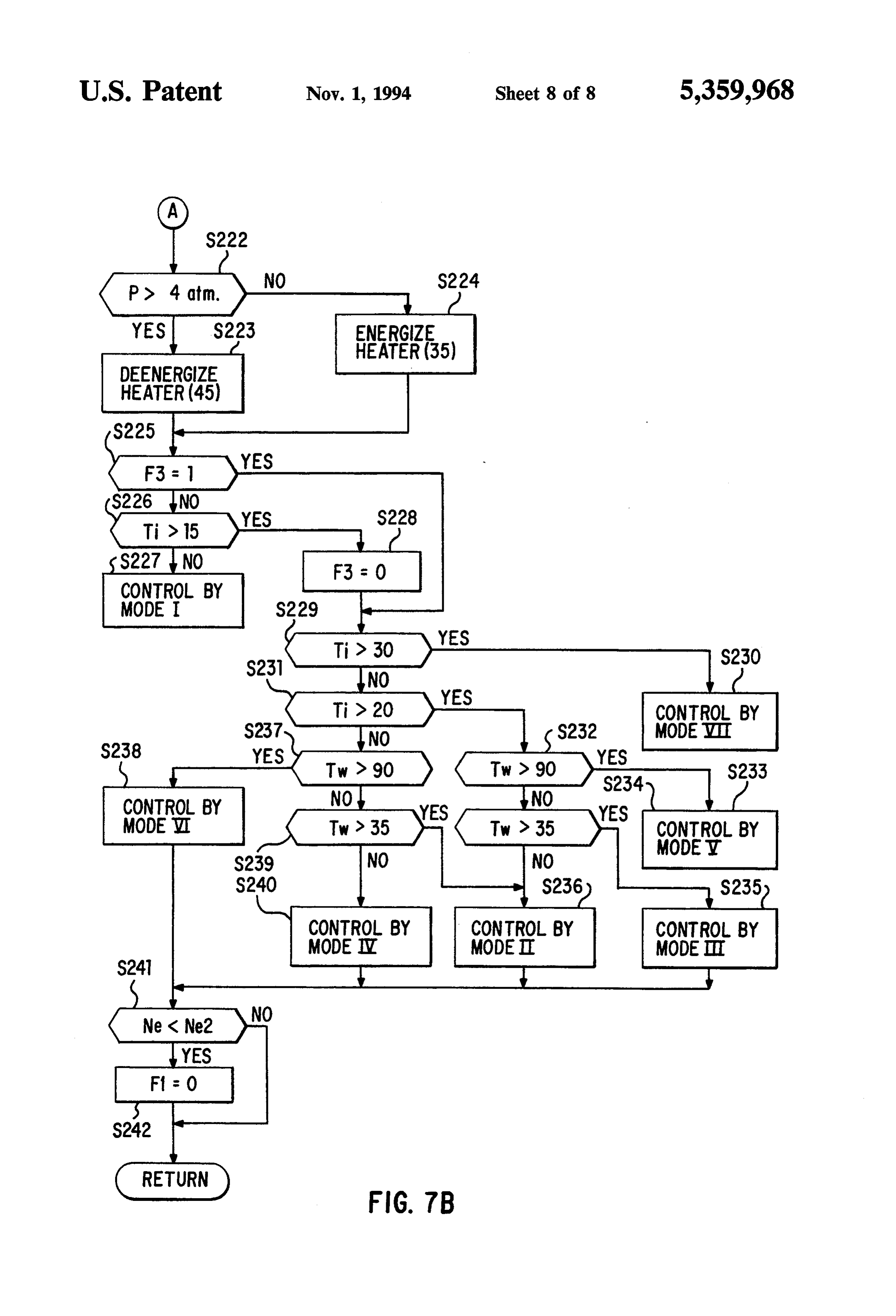
the hydrogen engine. Once the hydrogen engine is op FIG. 6 is a diagram of control patterns having differ erating continuously, when the temperature of coolant entratios of open/engaged time to closed/stopped time; circulated through the hydrogen storage alloy tanks 10 and exceeds the specific temperature range, a bypassing FIGS. 7A and 7B are a flow chart illustrating a con coolant from the hydrogen storage alloy tanks is mixed trolshown sequence for the hydrogen gas supply system in FIG. 5.
with the coolant directed from the engine toward the hydrogen storage alloy tanks. In other words, the tem DETAILED DESCRIPTION OF THE perature of the coolant having passed through the hy 15 PREFERRED EMBODIMENTS drogen storage alloy tanks drops before it reenters due Referring to the drawings in detail, in particular to to release of hydrogen which is accompanied by heat FIG. 1, a hydrogen engine, such as a two cylinder ro absorption. By suitably mixing the coolant from the tary engine 1 provided with a hydrogen gas supply tanks with the coolant from the engine, the coolant is 20 device in accordance with a preferred embodiment of always maintained within the specific range of tempera tures when the it enters the hydrogen storage alloy the present invention is shown. In addition to an intake line 2 and exhaust lines 3, a hydrogen gas supply line 5, tanks. In this manner, even when the temperature of extending from a plurality of hydrogen storage alloy coolant rises after the hydrogen engine has been started, tanks or metal hydride alloy tanks 4 are connected to the continuous release of hydrogen is achieved by main 25 rotary engine 1. The hydrogen gas supply line 5 is pro taining the optimal release pressure in the hydrogen vided with a pressure regulator 6. Further, hydrogen storage alloy tank. gas supply line 5 is provided with flow regulators 9 and Accordingly, as set forth above, since it is possible to 10 between pressure regulator 6 and engine 1, regulat supply hydrogen gas to the hydrogen engine from ing the supply of hydrogen gas to hydrogen engine 1, startup to drive using only a single type of hydrogen which are linked to an accelerator pedal 7 and a step storage alloy tanks, improvements in startup reliability motor 8 which is driven by an engine control device and fuel efficiency are realized over the conventional (not shown), respectively. Between pressure regulator 6 system with different two types of hydrogen storage and metal hydride alloy tanks 4, hydrogen gas supply alloy tanks, i.e. startup tanks and drive or mobile tanks, line 5 is provided from the side of pressure regulator 6 in which drive is engaged subsequent to warming after 35 with a hydrogen supply valve 11, a hydrogen gas main startup. Moreover, as set forth above, since the hydro valve 12, and a relief valve 13. A pressure sensor 14 and gen storage alloy tanks do not have to be high pressure a gas flowmeter 15 are connected to hydrogen gas sup containers, weight reduction and simplification of the ply line 5 between supply valve 11 and main valve 12. A configuration of the system as a whole are possible. hydrogen gas replenishment line 16 is also connected to By forcing a coolant to be circulated through a heat hydrogen gas supply line 5 between main valve 12 and exchanger and thereafter through the engine and the relief valve 13. A hydrogen gas replenishment valve 17 hydrogen storage alloy tanks, overheated coolant is not is installed in hydrogen gas replenishment line 16 and a supplied to the hydrogen storage alloy tanks, so that, replenishment gas flowmeter 18 is connected to hydro even without a wide range of adjustment in the propor gen gas replenishment line 16. Main valve 12 and hydro tion of coolant supplied from the engine and mixed with 45 gen gas replenishment valve 17 are both configured as the coolant from the hydrogen storage alloy tanks, it is manual cut-off valves.
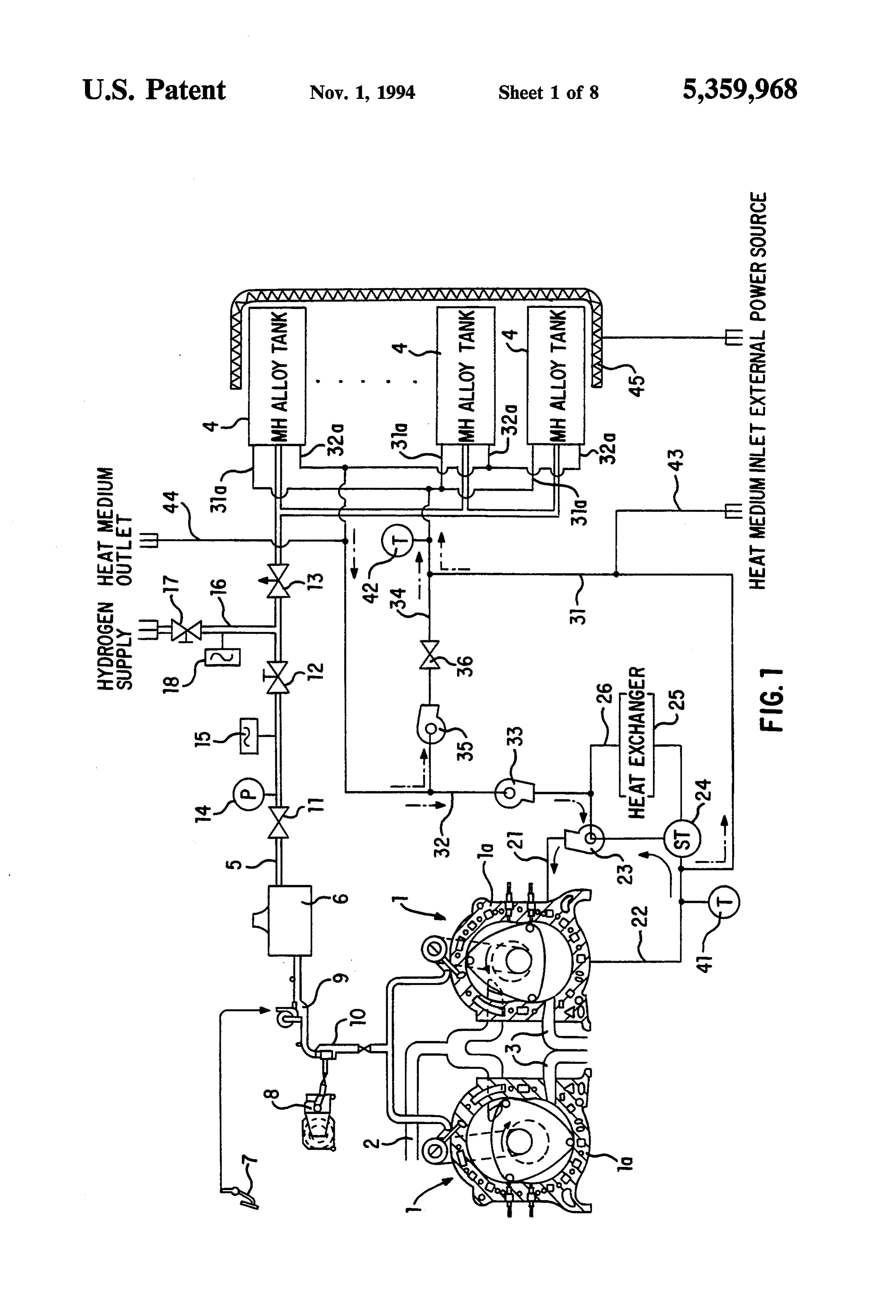
realized to keep small the variation in temperature of Structural engine parts, including rotary housings 1a, coolant circulating the hydrogen storage alloy tanks. As 1a, of rotary engine 1 permit circulation of coolant a result, since it is possible to more accurately maintain water to be prevented from being overheating. To this the temperature of the coolant entering the hydrogen 50 end, a coolant delivery line 21 and a coolant return line storage alloy tanks within the specified temperature 22 are connected to rotary engine 1. As indicated by range, it becomes possible to sustain the release of hy solid arrows, coolant water driven by a coolant circu drogen under more stable conditions. lating pump 23 circulates in coolant delivery line 21 BRIEF DESCRIPTION OF THE DRAWINGS 55 through rotary engine 1 to coolant return line 22. A thermostat 24 is positioned on coolant return line 22. A
The above and other objects and features of the pres bypass line 26 provided with a heat exchanger 25, for ent invention will be apparent to those skilled in the art example a radiator, is connected to coolant return line from the following description of preferred embodi 22 between thermostat 24 and the inlet of coolant circu ments when considered in conjunction with the draw lating pump 23. When the temperature of the coolant ings. In the drawings, the same reference numerals have 60 water exceeds the setting of thermostat 24, a passage been used to denote same or similar elements through from coolant return line 22 to bypass line 26 is opened Out. within thermostat 24 and the coolant water flows FIG. 1 is a schematic view of a hydrogen gas supply through heat exchanger 25, resulting in cooling of the system in accordance with a preferred embodiment of overheated coolant water by transfer of heat to the the present invention; 65 atmospheric air.
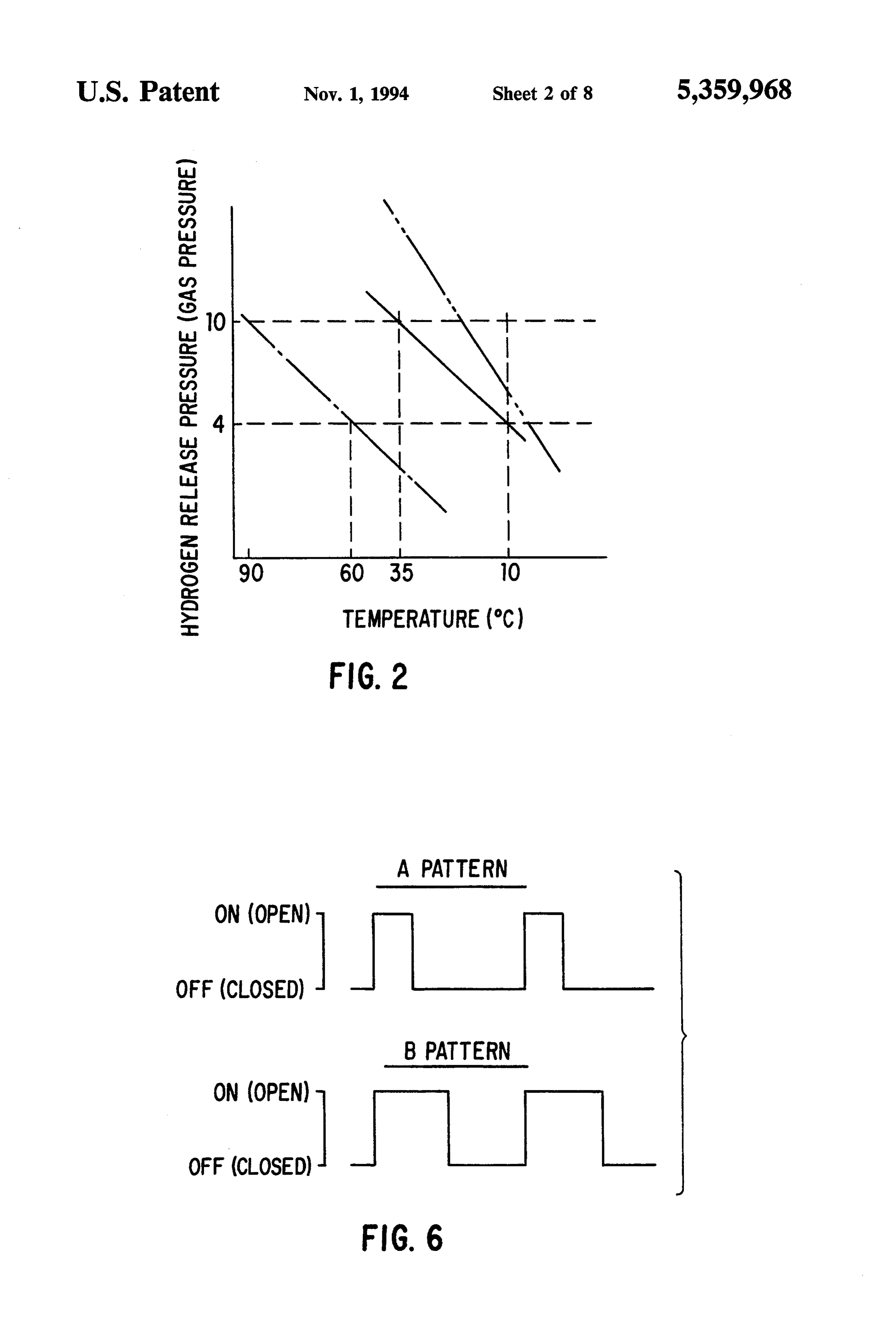
FIG. 2 is a graph showing the temperature-release A heat medium delivery line 31 is connected to cool pressure characteristics of a metal hydride alloy in the ant return line 22 on the side of rotary engine 1 with metal hydride alloy tanks; respect to thermostat 24 so as to accept a portion of the
Page 12
flow of circulating coolant water from coolant return cordingly, it is necessary to maintain metal hydride line 22 and supply it as heat medium to each of metal alloy tanks 4 within a temperature range of 10-35 C. hydride alloy tanks 4. The forward end of heat medium to ensure continuous operation of hydrogen engine 1 on delivery line 31 forks into a number of branch delivery hydrogen gas released by metal hydride alloys con lines 31a which are connected to metal hydride alloy tained in metal hydride alloy tanks 4. To this end, the tanks 4, respectively. Additionally, a heat medium re circulation of coolant water to metal hydride alloy turn line 32 is connected to bypass line 26 between tanks 4 is controlled by a control device (not shown) coolant circulating pump 23 and heat exchanger 25. The based on the temperatures detected by coolant tempera forward end of heat medium return line 32 forks into a ture sensor 41 and heat medium inlet temperature sensor number of branch return lines 32a which are connected 10 42.
to metal hydride alloy tanks 4, respectively. Circulation A specific example of the circulation control in the line of a circulation system comprises heat medium hydrogen engine system of this type mounted in a vehi delivery line 31 and heat medium return line 32, provid cle will be hereafter described. It is noted that the ten ing circulation through metal hydride alloy tanks 4. perature of coolant water is generally approximately Through the action of heat medium circulating pump 15 identical to an external temperature when hydrogen (Pc) 33 positioned on heat medium return line 32, a engine 1 is not started, and may rise to levels exceeding, portion of the coolant water circulating through rotary for example, 90° C. during continuous operation of hydrogen engine 1 is supplied from coolant return line hydrogen engine 1. During startup, main valve 12 is 22 through heat medium delivery line 31 and branch manually opened and, then, when the ignition key (IG) delivery lines 31a to each of metal hydride alloy tanks 4, 20 is switched on, coolant circulating pump 23 and heat and subsequently returned through branch return lines medium circulating pump (Pc) 33 start up, the circula 32a, heat medium return line 32, and bypass line 26 totion of coolant water to hydrogen engine 1 is initiated, with a portion of the coolant water beginning to circu coolant delivery line 21, as indicated by broken arrows.
A heat medium bypass line 34 is positioned between late to metal hydride alloy tanks 4. Simultaneously, and connects heat medium delivery line 31 and heat 25 hydrogen supply valve 11 is opened. At this time, hy medium return line 32. A bypass pump (Pb) 35 and a drogen engine 1 is started as soon as a stable pressure of bypass valve (Vb) 36 are positioned on heat medium greater than 4 atm. is detected by pressure sensor 14, bypass line 34 as a means of temperature regulation. which may require, for example, 5 seconds. In this in When bypass valve (Vb) 36 is opened and bypass pump stance, if, because the external air temperature is less (Pb) 35 is actuated, a portion of the coolant water circu 30 than 10 C. and accordingly, the temperature of metal lating through heat medium return line 32 to bypass line hydride alloy tanks 4 is low, the pressure detected by 26, as indicated by dot-dash-dot arrows, is diverted pressure sensor 14 is less than 4 atm., a low-temperature through heat medium bypass line 34 to heat medium indicator (see FIG. 3) provided on the instrument panel delivery line 31. Thus, this diverted coolant water is in the vehicle compartment lights up. At this time, elec mixed with coolant water supplied by coolant return 35 tricity is provided to heater 45 to heat metal hydride line 22 in the forward end of heat medium delivery line alloy tanks 4. From then on, heater 45 is continuously 31, and the mixed coolant water enters each of the metal controlled by switching on and off its electrical power hydride alloy tanks 4. Further, a temperature sensor 41, source based on the pressure detected by pressure sen which detects the temperature Tw of coolant water sor 14. The temperature in metal hydride alloy tanks 4 flowing through coolant return line 22, is connected is raised by supplying heater 45 with electric power near the connecting point of coolant return line 22 and and, when the release pressure of hydrogen gas reaches heat medium delivery line 31. A temperature sensor 42, 4 atm., hydrogen engine 1 is started in the above which detects as the entering heat medium temperature described manner.
Ti the temperature of coolant water flowing into metal Once hydrogen engine 1 has started, heat medium hydride alloy tanks 4, is connected to the forward end 45 circulating pump (Pc) 33 remains on until the tempera of heat medium delivery line 31. ture of the coolant water, circulating through hydrogen A heater 45 is wound around metal hydride alloy engine 1, has reached 35° C. A portion of the coolant tanks 4. As will be described later, when the external air water flowing through coolant return line 22 is diverted temperature is low during startup, electricity is supplied to heat medium delivery line 31, from which it passes to heater 45 by an external power source, such as a 50 through branch delivery lines 31e, flowing into each of battery, to heat metal hydride alloy tanks 4 so as to metal hydride alloy tanks 4. It, then, circulates from cause hydrogen gas to be released. A low-temperature branch return lines 32a through heat medium return line heat medium supply line 43 and a low-temperature heat 32, returning to hydrogen engine 1. medium discharge line 44 are connected to heat medium As a result of a rise in the temperature of the coolant delivery line 31 and heat medium return line 32, respec 55 water due to continuous operation of hydrogen engine tively, so as to circulate low temperature heat medium 1, when a coolant temperature Tw exceeding 35 C. is to metal hydride alloy tanks 4 from the exterior during detected, bypass pump (Pb) 35 is actuated or switches the occlusion occurring when hydrogen gas is supplied on, and bypass valve (Vb) 36 is opened, so that the to metal hydride alloy tanks 4 from the exterior. coolant water, flowing from metal hydride alloy tanks 4 A metal hydride alloy, which has the temperature to hydrogen engine 1 through heat medium return line release pressure characteristics shown by the solid line 32, is bypassed through heat medium bypass 34. This in FIG. 2, is stored in each of the metal hydride alloy causes the bypassed coolant water and the coolant tanks 4. In other words, hydrogen is released to hydro water supplied from hydrogen engine 1 to mix with gen engine 1 at about 10 C. at the minimum optimal each other, entering metal hydride alloy tanks 4. release pressures of, for instance, 4 atm. Then, when the 65 Since hydrogen is released in metal hydride alloy release pressure increases with a rise in temperature to tanks 4 by endothermic reaction, the coolant water about 35 C., hydrogen is released at the maximum passing through metal hydride alloy tanks 4 decreases optimal release pressure of, for instance, 10 atm. Ac its temperature to, for example, approximately 15 C.
Page 13
from the temperature when it enters into metal hydride temperature heat medium discharge line 44, respec alloy tanks 4. By appropriately mixing the coolant tively. While the low-temperature heat medium is being water that has been thus cooled with a high temperature supplied to metal hydride alloy tanks 4, hydrogen is of heat medium supplied from hydrogen engine 1, the supplied to metal hydride alloy tanks 4 through hydro temperature of the coolant water can be held below 35 gen gas replenishment line 16. At this time, the value, C. when entering metal hydride alloy tanks 4. The mix which is a result of subtraction of the value measured by ture ratio of coolant water can be adjusted by intermit supply gas flowmeter 15 from the value measured by tently actuating bypass pump (Pb) 35 and opening by gas flowmeter 18 connected to hydrogen gas replenish pass valve (Vb) 36. In this intermittent control, the ment line 16, is displayed as the quantity of fuel in metal greater the temperature of coolant water supplied by 10 hydride alloy tanks 4 by the fuel indicator (not shown) hydrogen engine 1 is, the longer the period of bypass on the instrument panel in the vehicle compartment. pump (Pb) 35 remains actuated and the longer bypass As shown in FIG. 3, the hydrogen gas supply system valve (Vb) 36 remains open. is controlled by a control unit 100 to which various In this manner, coolant used to cool hydrogen engine signals representative of pressure, temperatures, engine 1 is exploited as a heat medium to transport heat re 15 speed, etc are input and which provides control signals quired for the release of hydrogen in metal hydride to pump and valve drive circuits 101 and 102. alloy tanks 4. With this control, the temperature of Referring to FIG. 4, which is a flow chart illustrating metal hydride alloy tanks 4 can be maintained within a control sequence, just after starting of the sequence the specified range of 10-35 C. over nearly the entire for the hydrogen gas supply system shown in FIG. 1, a temperature range of the coolant as it heats up due to 20 decision is made at step S101 as to whether a flag F1 has operation of hydrogen engine 1. Accordingly, in con been set to “1.' If the answer is "YES,' a decision is trast to conventional hydrogen gas supply devices made at step S102 as to whether a release pressure is equipped with two types of metal hydride alloy tanks, higher than the minimum optimal release pressures of 4 such as a startup tank and a mobile tank, in which atm. If “YES,” another decision is made at step S103 as warming is performed subsequent to starting up of hy 25 to whether a flag F2 has been set to “1.” After setting drogen engine 1 using hydrogen from the startup tank, the flag F2 to “1” at step S105 subsequent to having and then, drive is initiated by switching over to the reset a timer at step S104 if the flag F2 has not been set mobile tank, the gas supply device according to the to “1,” or directly if the flag has been set to “1,” the present invention is enabled to stably supply hydrogen timer starts to count a time T at step S106. Then, a gas to hydrogen engine 1 from startup to drive by the decision is made at step S107 as to whether five seconds provision of only one type of metal hydride tanks 4, have passed. If the answer to the decision is "YES,' which are approximately identical with a startup tank, then, the flag F2 is setto “0” at step S108. Subsequently, so as to obviate the need for warming of hydrogen at step S109, a decision is made as to whether the igni engine 1 and permit drive immediately after the startup tion switch (IG) has been turned on. When ignition of hydrogen engine 1. This raises the reliability of 35 switch (IG) has been turned on, then, a decision is made startup and improves fuel efficiency of hydrogen engine based on a speed detected by the speed sensor (see FIG. 1. Moreover, since there is no need to use high-pressure 3) at step S110 as to whether the rotational speed Ne of containers for metal hydride alloy tanks 4, simplifica the engine 1 is higher than a first specific rotational tion and weight reduction of the configuration of a speed Ne1 which is a critical speed to judge whether the hydrogen engine system as a whole are possible. 40 engine has actually started. If the answer is "YES,' Control modes of the hydrogen engine system at then, after setting the flag F1 to “1” S111 the sequence times other than startup and drive are as follows: returns.
(1) When stopped, turning the ignition key off opens On the other hand, if the answer to the decision made all of the valves and stops all of the pumps. at step S102 is "NO,” then, the heater energizing circuit (2) While the vehicle is not operated, all of the valves 45 is actuated to energize the heater 45 at step S112. There are kept open and all of the pumps are maintained after, after turning on the indicator, such as a lamp, at stopped since the ignition key remains turned off. step S113, the sequence returns. When the answer to (3) During emergencies, such as when drive becomes any decisions made at steps S107, S109 and S110 is unstable due to abnormal combustion in hydrogen en “NO,” the sequence returns.
gine 1 and when backfiring occurs, an emergency 50 After starting of the sequence, if the answer to the switch is thrown off by the operator to shut down the decision made at step S101 is “YES,' then, a decision is supply of hydrogen into hydrogen engine 1 so as to made at step S114 as to whether a release pressure is close hydrogen supply valve 11 even with the ignition higher than the minimum optimal release pressures of 4 key on and thereafter, close all other valves and stop all atm. As a result of the decision, the heater 45 is deener of the pumps. 55 gized at step S115 when the answer is “YES,' or is (4) When hydrogen leakage is detected by a hydro energized at step S116 when the answer is “NO.” gen sensor, a warning light lights up on the instrument Thereafter, a decision is made at step S117 as to panel and a buzzer simultaneously sounds to give a whether the temperature Tw of coolant water flowing warning. I through coolant return line 22 detected by the tempera (5) In collisions, when pressure sensor 14 detects a 60 ture sensor 41 is higher than 35 C. When a temperature sudden pressure drop, all of the valves are closed and all higher than 35° C. is detected, a duty rate D, at which of the pumps are stopped. the pump 35 and the valve 36 are operated, is calculated When filling metal hydride alloy tanks 4 with hydro at step S118. According to the calculated duty ratio, the gen, after the ignition key has been switched off, an pump 35 and the valve 36 are operated at step S119 nd external hose used for hydrogen replenishment is con 65 S120, respectively. On the other hand, if the answer to nected to hydrogen gas replenishment line 16, and the decision made at step S117 is “NO,” then, after water supply and discharge hoses are connected to driving the pump 33 at step S 123 and stopping the low-temperature heat medium supply line 43 and low pump 35 at step S124, the valve 36 is closed. Thereafter,
Page 14
a decision is made at step S121 as to whether the rota Control mode II is a control that is initiated when tional speed Ne of the engine 1 is higher than a second supplying electric power to heater 45 during startup is specific rotational speed Ne2 which is a critical speed to not necessary, or when heat medium inlet temperature judge whether the engine possibly stops. After setting Tiis detected to have exceeded the predetermined criti the flag F2 to “0” at step S122 If the answer is “YES,” cal temperature of 15 C. while control mode I is still in or otherwise directly if the answer is "NO,' the se effect. A coolant temperature Tw of 35° C. or less and quence returns. a heat medium inlet temperature Ti of between 10-35 Referring to FIGS. 5 and 6, showing a hydrogen C. are preconditions for this control. From the control engine, such as a two cylinder rotary engine 1, provided mode I, second bypass valve (V2) 54 is closed and first with a hydrogen gas supply device in accordance with 10 bypass valve (V1) 51 is opened to direct the coolant another preferred embodiment of the present invention, water that has been warmed several degrees in tempera in which, for the sake of convenience, parts having ture by passing through hydrogen engine 1 through functions identical to parts shown in the previous em heat medium delivery line 31 to metal hydride alloy bodiment are labeled identically, in addition to the con tanks 4. This coolant water circulates through metal figuration shown in FIG. 1, a first bypass valve (V1) 51 5 hydride alloy tanks 4 in a manner that maintains the and aheat medium main valve (Vm) 52 are positioned in temperature there at 10-35° C.
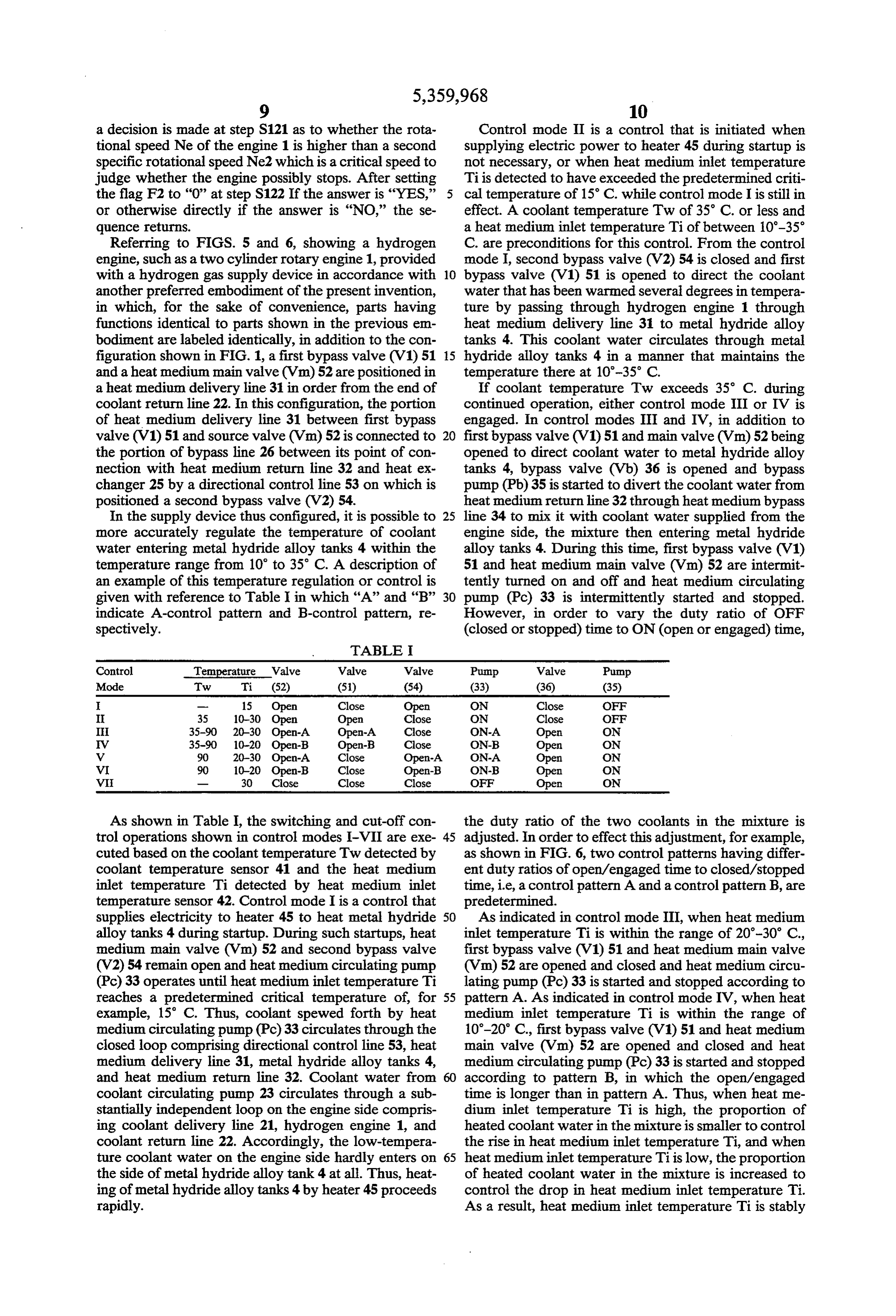
a heat medium delivery line 31 in order from the end of If coolant temperature Tw exceeds 35 C. during coolant return line 22. In this configuration, the portion continued operation, either control mode III or IV is of heat medium delivery line 31 between first bypass engaged. In control modes III and IV, in addition to valve (V1) 51 and source valve (Vm) 52 is connected to 20 first bypass valve (V1) 51 and main valve (Vm) 52 being the portion of bypass line 26 between its point of con opened to direct coolant water to metal hydride alloy nection with heat medium return line 32 and heat ex tanks 4, bypass valve (Vb) 36 is opened and bypass changer 25 by a directional control line 53 on which is pump (Pb) 35 is started to divert the coolant water from positioned a second bypass valve (V2) 54. heat medium return line 32 through heat medium bypass In the supply device thus configured, it is possible to 25 line 34 to mix it with coolant water supplied from the more accurately regulate the temperature of coolant engine side, the mixture then entering metal hydride water entering metal hydride alloy tanks 4 within the alloy tanks 4. During this time, first bypass valve (V1) temperature range from 10 to 35 C. A description of 51 and heat medium main valve (Vm) 52 are intermit an example of this temperature regulation or control is tently turned on and off and heat medium circulating given with reference to Table I in which “A” and “B” 30 pump (Pc) 33 is intermittently started and stopped. indicate A-control pattern and B-control pattern, re However, in order to vary the duty ratio of OFF spectively. (closed or stopped) time to ON (open or engaged) time,
TABLE I
Control Temperature Valve Valve Valve Pump Valve Pump
Mode Tw Ti (52) (51) (54) (33) (36) (35)
I 35 10-30 Open Open Close ON Close OFF
I 35-90 20-30 Open-A Open-A Close ON-A Open ON
V 35-90 10-20 Open-B Open-B Close ON-B Open ON
V 90 20-30 Open-A Close Open-A ON-A Open ON
VI 90 10–20 Open-B Close Open-B ON-B Open ON
VI 30 Close Close Close OFF Open ON
As shown in Table I, the switching and cut-off con the duty ratio of the two coolants in the mixture is trol operations shown in control modes I-VII are exe 45 adjusted. In order to effect this adjustment, for example, cuted based on the coolant temperature Tw detected by as shown in FIG. 6, two control patterns having differ coolant temperature sensor 41 and the heat medium ent duty ratios of open/engaged time to closed/stopped inlet temperature Ti detected by heat medium inlet time, i.e., a control pattern A and a control pattern B, are temperature sensor 42. Control mode I is a control that predetermined.
supplies electricity to heater 45 to heat metal hydride 50 As indicated in control mode III, when heat medium alloy tanks 4 during startup. During such startups, heat inlet temperature Ti is within the range of 20-30 C, medium main valve (Vm) 52 and second bypass valve first bypass valve (V1) 51 and heat medium main valve (V2) 54 remain open and heat medium circulating pump (Vm) 52 are opened and closed and heat medium circu (Pc) 33 operates until heat medium inlet temperature Ti lating pump (Pc) 33 is started and stopped according to reaches a predetermined critical temperature of, for 55 pattern A. As indicated in control mode IV, when heat example, 15 C. Thus, coolant spewed forth by heat medium inlet temperature Ti is within the range of medium circulating pump (Pc)33 circulates through the 10-20 C., first bypass valve (V1) 51 and heat medium closed loop comprising directional control line 53, heat main valve (Vm) 52 are opened and closed and heat medium delivery line 31, metal hydride alloy tanks 4, medium circulating pump (Pc) 33 is started and stopped and heat medium return line 32. Coolant water from according to pattern B, in which the open/engaged coolant circulating pump 23 circulates through a sub time is longer than in pattern A. Thus, when heat me stantially independent loop on the engine side compris dium inlet temperature Ti is high, the proportion of ing coolant delivery line 21, hydrogen engine 1, and heated coolant water in the mixture is smaller to control coolant return line 22. Accordingly, the low-tempera the rise in heat medium inlet temperature Ti, and when ture coolant water on the engine side hardly enters on 65 heat medium inlet temperature Ti is low, the proportion the side of metal hydride alloy tank 4 at all. Thus, heat of heated coolant water in the mixture is increased to ing of metal hydride alloy tanks 4 by heater 45 proceeds control the drop in heat medium inlet temperature Ti. rapidly. As a result, heat medium inlet temperature Ti is stably
Page 15
maintained within the range of 10-30° C. Further, whether a release pressure is higher than the minimum when coolant temperature Tw increases to above a optimal release pressures of 4 atm. If “YES,' another predetermined critical temperature of, for example, 90' decision is made at step S203 as to whether a flag F2 has C., control mode V or VI is engaged. In these modes, been set to “1,” After setting the flag F2 to “1” at step from the state of control mode III or control mode IV, S205 subsequent to having reset a timer at step S204 if first bypass valve (V1) 51 is closed and second bypass the flag F2 has not been set to “1,” or otherwise directly valve (V2) 54 is opened. At this time, the route of cool if the flag F2 has been set to “1,” then, control is con ant water circulating through the side of hydrogen ducted in the control mode II at step S206. The timer engine 1 is altered to run through thermostat 24 along starts to count a time T at step S207. Then, a decision is coolant return line 22 to heat exchanger 25 positioned 10 made at step S208 as to whether five seconds have on bypass line 26. Even a coolant temperature Tw ex passed. If the answer to the decision is “YES,' then, the ceeds 90° C., it decreases to, for example, about 60° C. flag F2 is set to “0” at step S209. Subsequently, at step after having passed through heat exchange 25 due to S210, a decision is made as to whether the ignition transfer of heat to the outside air. A portion of this switch (IG) has been turned on. When ignition switch coolant water is directed through directional control 15 (IG) has been turned on, then, a decision is made based line 53 and heat medium delivery line 31 to metal hy on a speed detected by the speed sensor at step S211 as dride alloy tanks 4. Even in such cases, heat medium to whether the rotational speed Ne of the engine 1 is inlet temperature Ti is stably maintained within the higher than a first specific rotational speed Nel. If the range of 10-30 C. This is accomplished when the heat answer is “YES,” then, after setting the flag F1 to “1” medium inlet temperature Ti is between 20-30° C. by 20 at step S212, the sequence returns. control mode V, in which opening and closing of sec On the other hand, if the answer to the decision made ond bypass valve (V2) 54 and heat medium supply at step S202 is "NO,” then, the heater energizing circuit source valve (Vm) 52 and starting and stopping of heat is actuated to energize the heater 45 at step S213. There medium circulating pump (Pc) 33 are executed accord after, after turning on the indicator, such as a lamp, at ing to the control pattern A, and when the heat medium 25 step S214, a decision is made at step S215 as to whether inlet temperature Ti is between 10-20 C., by control the heat medium inlet temperature Ti detected by tem mode VI, in which heat exchanger 25, second bypass perature sensor 42 is higher than 15 C. According to valve (V2) 54, and heat medium circulating pump (Pc) the result of the decision, a control is conducted in the 33 are controlled according to the control pattern B. control mode I at step S216 if the answer is "NO,' and When heat medium inlet temperature Ti exceeds 30 in the control mode II at step S217 if the answer is C., as indicated by control mode VII, first bypass valve "YES.” Thereafter, a decision is made at step S218 or (V1) 51, heat medium main valve (Vm) 52, and second S220 as to whether a flag F3 has been set to “1,” If the bypass valve (V2) 54 are all closed, and heat medium flag F3 has been set to “1” at step S218, the sequence circulating pump (Pc) 33 is stopped, so that no coolant returns. Otherwise, if the flag F3 has been set to “1” at is supplied from the side of hydrogen engine 1. Further, 35 step S218, then, after setting the flag F3 to “1” at step bypass valve (Vb) 36 is opened, and bypass pump (Pb) S219, the sequence returns. Similarly, if the flag F3 has 35 is started, so as to circulate the coolant water only not been set to “1” at step S220, the sequence returns. through heat medium bypass line 34 to metal hydride Otherwise, if the flag F3 has been set to "1" at step alloy tanks 4. By executing controls such as the control S220, then, after setting the flag F3 to “0” at step S221, modes set forth above, the coolant water with a temper the sequence returns.
ature adjusted to 10-30 C. is circulated to metal hy After starting of the sequence, if the answer to the dride alloy tanks 4 even during drive. From startup to decision made at step S201 is "YES,” then, a decision is drive, hydrogen gas is released from metal hydride made at step S222 as to whether a release; pressure is alloy tanks 4 within a pressure range of 4-10 atm., per higher than the minimum optimal release pressures of 4 mitting stable, uninterrupted drive. 45 atm. As a result of the decision, the heater 45 is deener In this embodiment, thermostat 24 functions in the gized at step S223 when the answer is "YES,” or is coolant circulation loop on the side of hydrogen engine energized at step S224 when the answer is "NO.” 1. When the loop is altered, coolant water is sent to Thereafter, a decision is made at step S225 as to metal hydride alloy tanks 4 after having passed through whether the flag F3 has been set to “1.” If the answer is heat exchanger 25. Accordingly, since coolant water SO "YES,” another decision is made at step S226 as to overheated on the side of hydrogen engine 1 is not whether the temperature Ti of coolant water at the heat directed to metal hydride alloy tanks 4, even though the medium inlet detected by the temperature sensor 42 is adjustment range of the mixture ratio of coolant water higher than 15 C. When a temperature higher than 15 supplied from the side of hydrogen engine 1 to bypass C. is not detected, a control is conducted in the control coolant water is not substantially large, by switching 55 mode I at step S227. On the other hand, when a temper between, for example, two control patterns such as the ature higher than 15 C. is not detected, the flag F3 is set control patterns A and B, the temperature of coolant to “0” at step S228 entering the hydrogen storage alloy tanks 4 can be reli When the flag F3 has not been set to “1” at step S225 ably maintained within the range of 10-30 C. As a or after setting the flag F3 to "0,’ decisions regarding result, the release of hydrogen can be sustained under coolant temperature are subsequently made. That is, a more stable conditions, and reliable drive can be as decision is made at step S229 as to whether the coolant sured. inlet temperature Ti is higher than 30 C. If the coolant Referring to FIG. 7, which is a flow chart illustrating inlet temperature Ti is higher than 30 C, then, a con a control sequence for the hydrogen gas supply system trol is conducted in the control mode VII at step S230. shown in FIG. 5, after starting of the sequence, the first 65 Otherwise, if the coolant inlet temperature Ti is less step at step S201 is to make a decision as to whether a than 30° C., a decision is further made at step S231 as to flag F1 has been set to “1.” If the flag F1 has not been whether the coolant inlet temperature Tiis higher than set to “1,” then, a decision is made at step S202 as to 20° C. If the coolant inlet temperature Tiis less than 20
Page 16
C., then, a decision is made at step S232 as to whether tered by the action of the thermostat in the engine side the coolant return temperature Tw detected by temper circulation loop cooling the engine, circulating coolant ature sensor 41 is higher than 90 C. If the answer to the through the heat exchanger provided to lower the tem decision is "YES,' then, a control is conducted in the perature of overheated coolant, a switch is made, send control mode V at step S233. However, if the coolant ing coolant having already passed through the above return temperature Tw is less than 90° C., then, a fur mentioned heat exchanger to the hydrogen storage ther decision is made at step S234 as to whether the alloy tanks, and not coolant that has yet to pass through coolant return temperature Tw detected by tempera the heat exchanger. Thus, since overheated coolant ture sensor 41 is higher than 35 C. According to the from the engine side is not supplied to the hydrogen decision, a control is conducted in the control mode III 10 storage alloy tanks, even though the adjustment range at step S235 if the coolant return temperature Tw is of the mixture ratio of coolant supplied from the engine higher than 35° C. or in the control mode II at step S236 side to bypass coolant is not substantially large, fluctua if less than 35 C. tion in the temperature of coolant entering the hydro Similarly, if the coolantinlet temperature Tiis higher gen storage alloy tanks can be kept small. As a result, than 20 C., a decision is made at step S237 as to 15 since the temperature of entering coolant can be reliably whether the coolant return temperature Tw detected by maintained within a specified temperature range, the temperature sensor 41 is higher than 90° C. If the an release of hydrogen can be maintained under more sta swer to the decision is "YES,' then, a control is con ble conditions.
ducted in the control mode VI at step S238. However, It is to be understood that although the present inven if the coolant return temperature Twisless than 90 C., 20 tion has been described with respect to preferred em then, a further decision is made at step S239 as to bodiments thereof, various other embodiments and vari whether the coolant return temperature Tw is higher ants may occur to those skilled in the art. Any such than 35 C. According to the decision, a control is con other embodiments and variants which fall within the ducted in the control mode II at step S236 if the coolant scope and spirit of the invention are intended to be return temperature Tw is higher than 35° C. or in the 25 covered by the following claims.
control mode IV at step S240 if less than 35 C. What is claimed is:
Subsequent to a control in any control modes I-VII, 1. A hydrogen gas supply system, having a tank after setting the flag F1 to “1” at step S242 if the rota which contains a hydride storage alloy and in which tional speed Ne is judged to be less the second specific hydrogen at a specific pressure is released within a rotational speed Ne2 at step S241 or directly if it is 30 specified range of temperatures and supplied to a inter judged to be higher than the second specific rotational nal combustion hydrogen engine, said hydrogen gas speed Ne2, the sequence returns. supply system comprising:
As described above, the hydrogen gas supply system a looped coolant circulation system, in which said for hydrogen engines of the present invention is pro engine and said tank are connected in parallel, for vided with hydrogen storage alloy tanks which releases 35 circulating a coolant through said engine and said hydrogen at a specific pressure required for operation tank; and of the hydrogen engine and within a specific tempera temperature regulation means, positioned in said ture range close to the ambient temperature; circulation looped coolant circulation system in parallel with lines which circulate engine coolant to the hydrogen both said engine and tank, for forcing said coolant storage alloy tanks; heat medium bypass lines which returning from said tank to mix with said coolant divert coolant circulating back to the engine side from delivered from said engine when said coolant from the hydrogen storage alloy tanks through the circula said engine is at above said specified range of tem tion lines and divert it to the intake sides of the hydro peratures so as to regulate the temperature of said gen storage alloy tanks; and a means of temperature coolant circulating said tank. regulation whereby, when the temperature of coolant 45 2. A hydrogen gas supply system as defined in claim supplied to the hydrogen storage alloy tanks from the 1, wherein said temperature regulation means comprises engine side during passage through the circulation lines a bypass line positioned in said looped coolant circula exceeds the above-described temperature range, a by tion system so as to allow said coolant returning from pass flow passing through a heat medium bypass line is said tank to bypass said engine and enter said coolant mixed with coolant from the engine side and directed 50 delivered from said engine.
into the hydrogen storage alloy tanks, thereby maintain 3. A hydrogen gas supply system as defined in claim ing the temperature of entering coolant within the 2, wherein said temperature regulation means further above-described temperature range. Thus, since it is comprises a pump which is actuated when said coolant possible to supply hydrogen gas to the hydrogen engine from said engine is at above said specified range of from startup to drive by providing only one type of 55 temperatures.
hydrogen storage alloy tank, startup efficiency is higher 4. A hydrogen gas supply system as defined in claim and greater fuel efficiency is possible than in the con 3, wherein said pump is kept actuated longer with an ventional configuration in which two different types of increase in temperature of said coolant. hydrogen storage alloy tanks are provided, one for 5. A hydrogen gas supply system as defined in claim startup and the other for drive, and drive is begun after 60 2, wherein said temperature regulation means further warming subsequent to startup. Moreover, further ef comprises a regulation valve which is opened when said fects are achieved in that since the use of high-pressure coolant from said engine is at above said specified range containers for the hydrogen storage alloy tanks is not of temperatures.
required, weight reduction and simplification of the 6. A hydrogen gas supply system as defined in claim configuration as whole are possible. 65 5, wherein said regulation valve is intermittently con A directional control line is provided in the above trolled such that the greater a temperature of said cool mentioned circulation lines so that when the above ant from said engine is, the longer the period of said described hydrogen engine side circulation loop is al regulation valve remains open.
Page 17
7. A hydrogen gas supply system as defined in claim 9. A hydrogen gas supply system as defined in claim 2, and further comprising heat exchange means, posi 8, 10. wherein said heat exchanger comprises a radiator. A hydrogen gas supply system as defined in claim tioned in said looped coolant circulation system and in 7, wherein said looped coolant circulation system com parallel with both of said engine and tank, through prises directional control means for directing said cool which said coolant circulating through said engine ant from said heat exchange means to said tank in place flows when the temperature of said coolant exceeds a of11. said coolant from said engine. A hydrogen gas supply system as defined in claim predetermined temperature, for cooling said coolant 1, further comprising electrical heating means for heat from said engine by transfer of heat to the atmospheric 10 ing said tank when a pressure at which hydrogen is air. released from said tank is lower than said specific pres 8. A hydrogen gas supply system as defined in claim Sle.
7, wherein said heat exchange means comprises a heat 12. A hydrogen gas supply system as defined in claim
exchanger and a thermostat which actuates when the 15 culates wherein said looped coolant circulation system cir a coolant through said tank bypassing said en temperature of said coolant exceeds said predetermined gine while said electrical heating means is heating said temperature to direct said coolant to said heat ex tank. k k k k changer.
Provenance
- Collection
- Cited prior art
- Original PDF
- patentimages.storage.googleapis.com →
- Filed
- 1993-07-29
- Pages
- 17
- Method
- pdftotext (the PDF's own text layer) + pdftoppm 300dpi page scans
- Source
- Google Patents bibliographic record
- Granted
- 1994-11-01
- Inventors
- Noriaki Shiraishi; Yoshio Mizushima; Kenji Takamuku; Masaki Kadokura; Mazda Motor Corp
- Transcribed from
- patentimages.storage.googleapis.com →