patent · US5462021
Hydrogen gas supply systems for hydrogen engine and method of supplying hydrogen gas to the hydrogen gas supply system
31 October 1995
Page 1 — bibliographic record
United States Patent (19) 11 Patent Number: 5,462,021 Minami et al. (45) Date of Patent: Oct. 31, 1995 54 HYDROGEN GAS SUPPLY SYSTEMS FOR 1216024 8/1989 Japan. HYDROGEN ENGINE AND METHOD OF 1216062 8/1989 Japan ............................. 123/DIG. 12 SUPPLYING HYDROGEN GAS TO THE 5-18260 1/1993 Japan ...... ... 123/DIG. 12 HYDROGEN GAS SUPPLY SYSTEM 5-18259 1/1993 Japan ...... ... 123/DIG. 12 0848730 7/1981 U.S.S.R. ........................ 23/DIG. 12 75) Inventors: Takanori Minami; Noriaki Shiraishi; OTHER PUBLICATIONS Tsutomu Shimizu; Kenji Takamuku;
Yoshinori Tsushio; Yoshio Mizushima; Automotive Engineering, vol. 86, No. 5, May 1978, Dallas, Kazuyuki Yoshimoto; Masaki Tex., US, pp. 78-81, D. Scott, "Hydrogen Fuel Ready For Kadokura, all of Hiroshima, Japan Bus Fleet'.
International Journal of Hydrogen Energy, vol. 11, No. 1, 73 Assignee: Mazda Motor Corporation, 1986, Oxford, GB, pp. 39-42, Davidson, "Development of Hiroshima, Japan a Hydrogen-Fuelled Farm Tractor'.
Automotive Engineering, vol. 92, No. 9, 1984, Dallas, Tex., 21 Appl. No.: 270,305 US, pp. 36-40, "Hydrogen Fuel Reduces Mining Machinery
Primary Examiner-Henry C. Yuen
Related U.S. Application Data Assistant Examiner-Erick Solis
Attorney, Agent, or Firm-Sixbey, Friedman, Leedom & 63 Continuation of Ser. No. 29,067, Mar. 10, 1993, abandoned. Ferguson; Gerald J. Ferguson, Jr.; Donald R. Studebaker 30 Foreign Application Priority Data 57) ABSTRACT Mar. 12, 1992 (JP Japan .................................... 4-090012 A hydrogen gas supply system for a hydrogen engine has a May 15, 1992 (JP) Japan .................................... 4-148526 hydrogen gas cartridge which is detachably attached to the (51) Int. C. ............. FO2B 43/08 engine. The cartridge has a casing in which hydrogen gas 52 U.S. Cl. ...................... 123/3; 123/DIG. 12; 220/562; storage alloy and a heating medium passage for heating the 220/581 hydrogen gas storage alloy are housed. The engine is pro 58) Field of Search ................................. 123/3, DIG. 12, vided with a hydrogen gas supply passage which leads 123/527; 220/562, 581 hydrogen gas discharged from the hydrogen gas cartridge to the engine, aheating medium supply passage which supplies 56) References Cited heating medium to the heating medium passage in the
through which the heating medium flows out of the hydro 4,548,044 10/1985 Sakai et al. ...................... 123/DIG. 12 gen gas cartridge is returned. The hydrogen gas cartridge is 5,092,281 3/1992 Iwaki et al. ...................... 123/DIG. 12 provided with a hydrogen gas takeout port, a heating FOREIGN PATENT DOCUMENTS medium inlet and a heating medium outlet. The hydrogen gas takeout port, the heating medium inlet and the heating 891746 4/1982 Belgium. medium outlet are respectively connected to and discon 2275725 1/1976 France. nected from the hydrogen gas supply passage, the heating 2458741 1/1981 France. medium supply passage and the heating medium return 58-170999 10/1983 Japan. passage in response to attachment and detachment of the 62-279264 12/1987 Japan. hydrogen gas cartridge.
1197301 8/1989 Japan. 23 Claims, 19 Drawing Sheets
Page 2
Drawing sheet — no readable text.
Page 3
Drawing sheet — no readable text.
Page 4
Drawing sheet — no readable text.
Page 5
Drawing sheet — no readable text.
Page 6
Drawing sheet — no readable text.
Page 7
Drawing sheet — no readable text.
Page 8
Drawing sheet — no readable text.
Page 9
Drawing sheet — no readable text.
Page 10
Drawing sheet — no readable text.
Page 11
Drawing sheet — no readable text.
Page 12
Drawing sheet — no readable text.
Page 13
Drawing sheet — no readable text.
Page 14
Drawing sheet — no readable text.
Page 15
Drawing sheet — no readable text.
Page 16
Drawing sheet — no readable text.
Page 17
Drawing sheet — no readable text.
Page 18
Drawing sheet — no readable text.
Page 19
Drawing sheet — no readable text.
Page 20
Drawing sheet — no readable text.
Page 21
HYDROGEN GAS SUPPLY SYSTEMS FOR hydrogen gas takeout ports of the respective cartridges may HYDROGEN ENGINE AND METHOD OF be connected either in parallel or in series, it is preferred that SUPPLYING HYDROGEN GAS TO THE the heating medium passages in the respective cartridges be HYDROGEN GAS SUPPLY SYSTEM connected in series so that the heating medium is supplied uniformly to all the cartridges. That is, when the heating
This application is a continuation of Ser. No. 029,067, medium passages are connected in parallel, a problem that filed Mar. 10, 1993, now abandoned. the engine coolant cannot be uniformly distributed to all the cartridges can arise due to stagnancy of the engine coolant
BACKGROUND OF THE INVENTION at particular portions. When the engine coolant is not 10 uniformly distributed to the fuel cartridges, the hydrogen gas 1. Field of the Invention
This invention relates to a hydrogen gas supply system for stored in the fuel cartridges is unevenly consumed. a hydrogen engine and a method of supplying hydrogen gas In the hydrogen gas supply system of the present inven to the hydrogen gas supply system. tion, since the hydrogen gas cartridges are removably 2. Description of the Prior Art attached to the hydrogen gas supply passage, the engine can 15 be replenished with hydrogen gas easily and quickly only by
Recently a so-called hydrogen engine has attracted special replacing the exhausted fuel cartridges with new fuel car interest as a clean engine which emits only water. (For tridges full of hydrogen gas.
example, see Japanese Unexamined Patent Publication No. Further since the hydrogen gas stored in the hydrogen 62(1987)-279264) storage alloy cannot be discharged unless it is heated, the However there remain various problems to be overcome 20 fuel cartridges can be handled in the same manner as general in order to put such a hydrogen engine into practical use. freight and can be transported and stored without use of For example, since hydrogen gas is generally distributed specialized facilities unlike the case where hydrogen gas is in a high pressure vessel and the fill quantity per volume is transported in the liquid state or the gas state. Further when small, the transportation cost becomes high and the price 25 stored in the hydrogen storage alloy, more hydrogen gas can becomes higher than gasoline which can be transported in a be stored per volume as compared with the case where liquid state. hydrogen gas is stored in the gas state. Thus the transpor Further in the case of a vehicle having a limited space, the lower cost tation cost.
is lowered and hydrogen gas can be supplied at quantity of hydrogen gas which can be carried by the vehicle is limited and accordingly the vehicle must be frequently 30 In accordance with another aspect of the present inven replenished with hydrogen gas. However in the present tion, there is provided a method of supplying hydrogen gas condition, facilities for replenishing hydrogen gas are not to a hydrogen gas supply system for a hydrogen engine enough, which obstructs popularization of the hydrogen characterized by the steps of storing hydrogen gas produced engines. at a hydrogen gas plant in a hydrogen gas storage alloy, 35 transporting the hydrogen gas as it is stored in the hydrogen
SUMMARY OF THE INVENTION gas storage alloy and supplying the hydrogen gas to the hydrogen gas supply system as it is stored in the hydrogen
In view of the foregoing observations and description, the gas storage alloy.
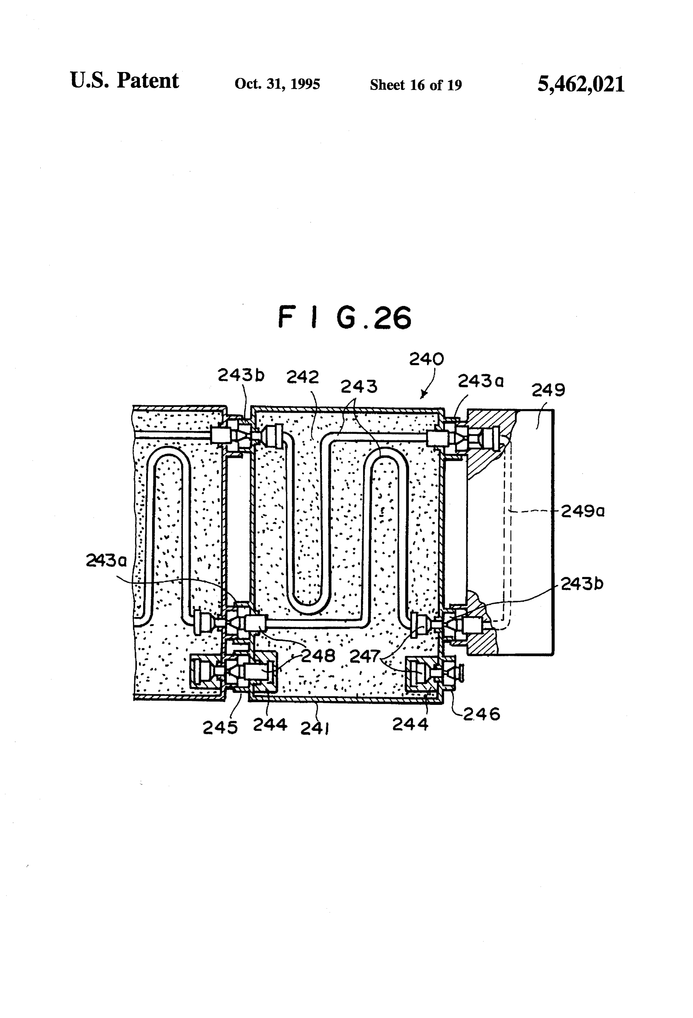
primary object of the present invention is to overcome the aforesaid difficulties in replenishing the hydrogen engine with hydrogen gas, thereby facilitating popularization of the BRIEF DESCRIPTION OF THE DRAWINGS hydrogen engines.
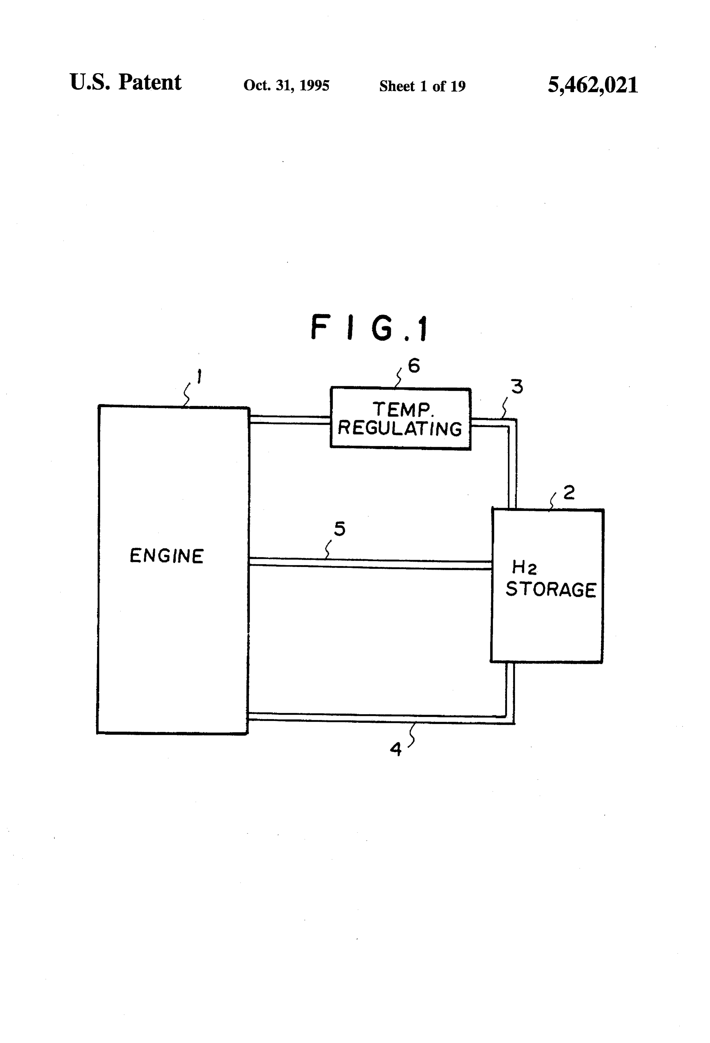
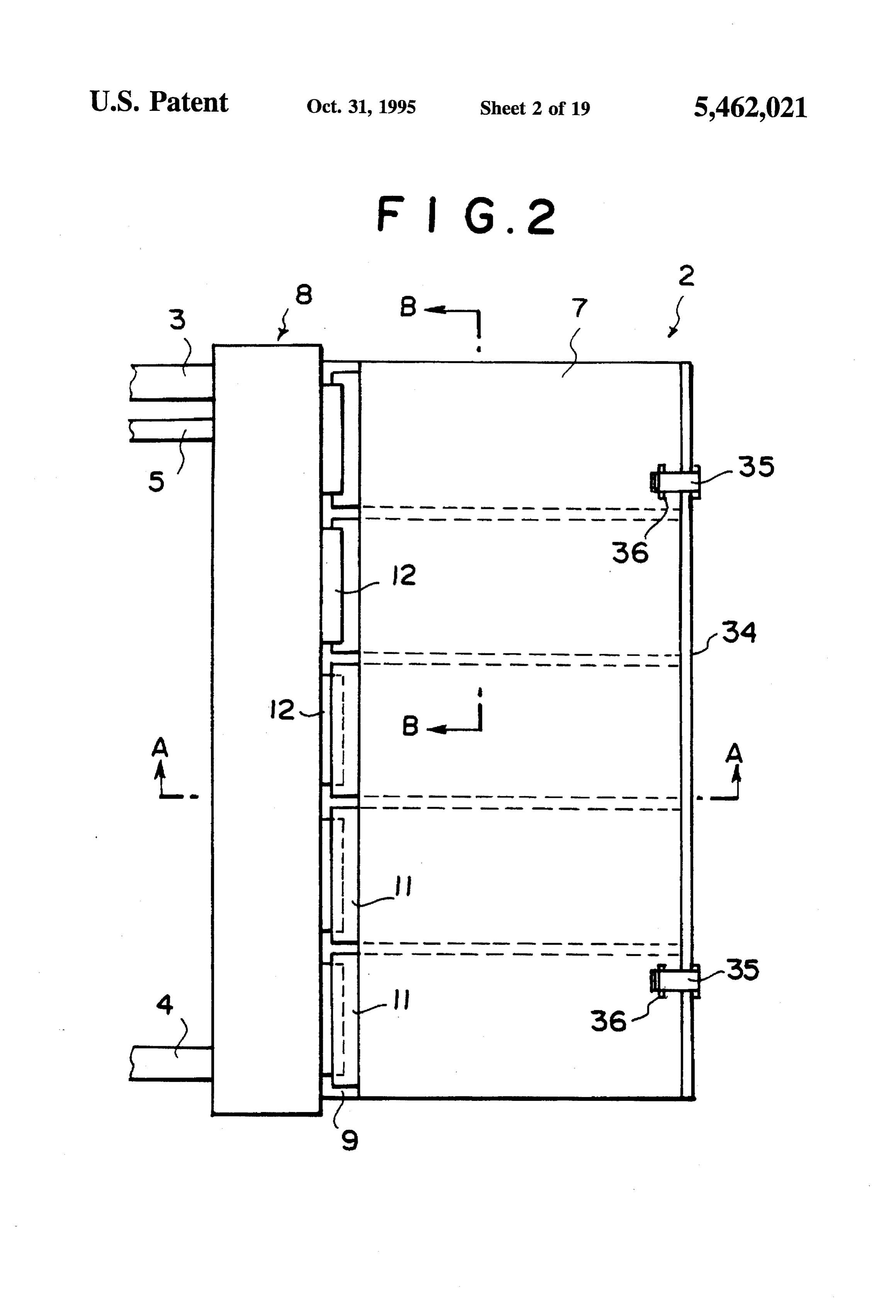
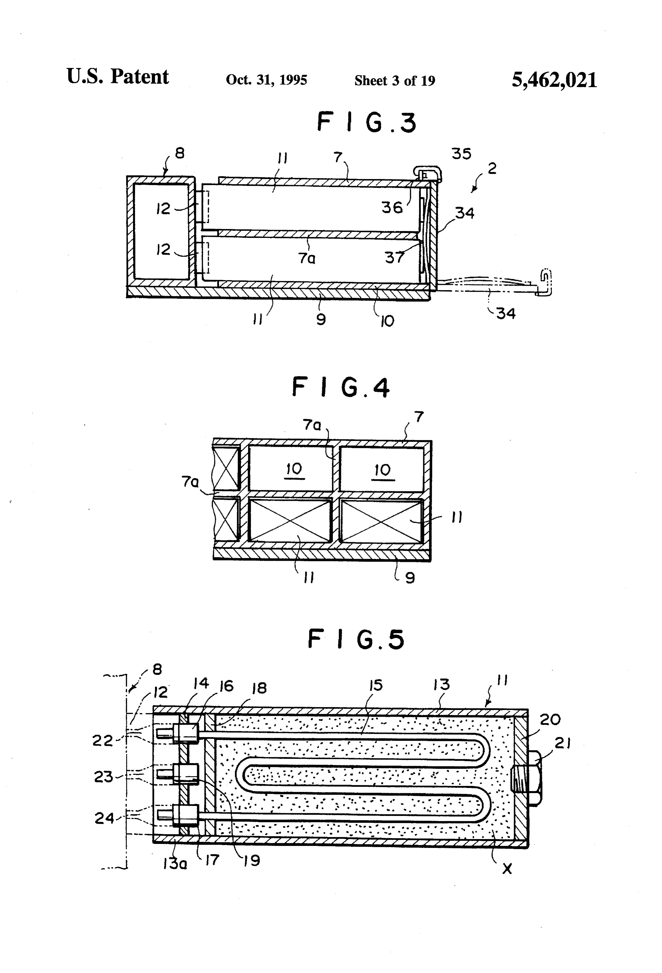
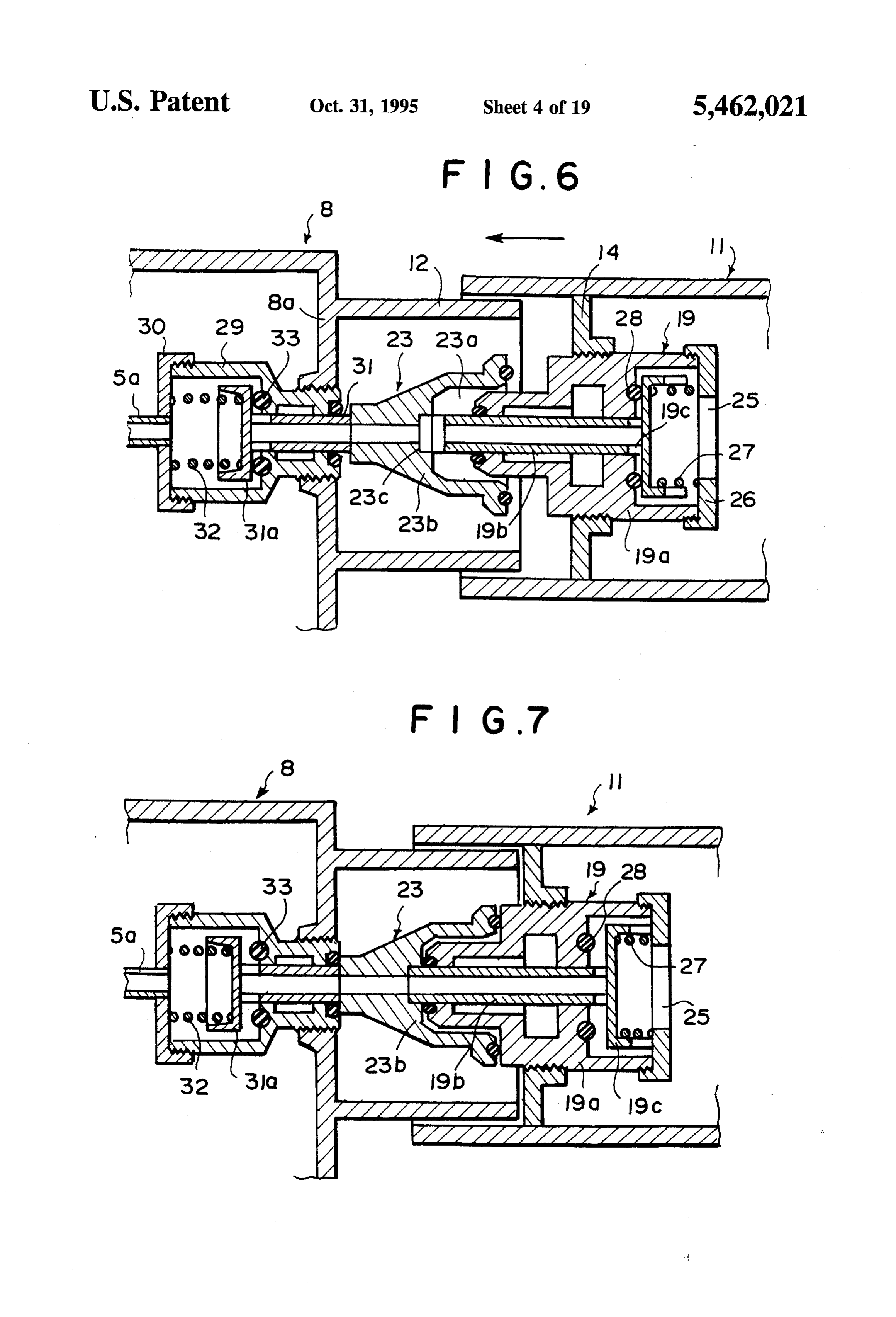
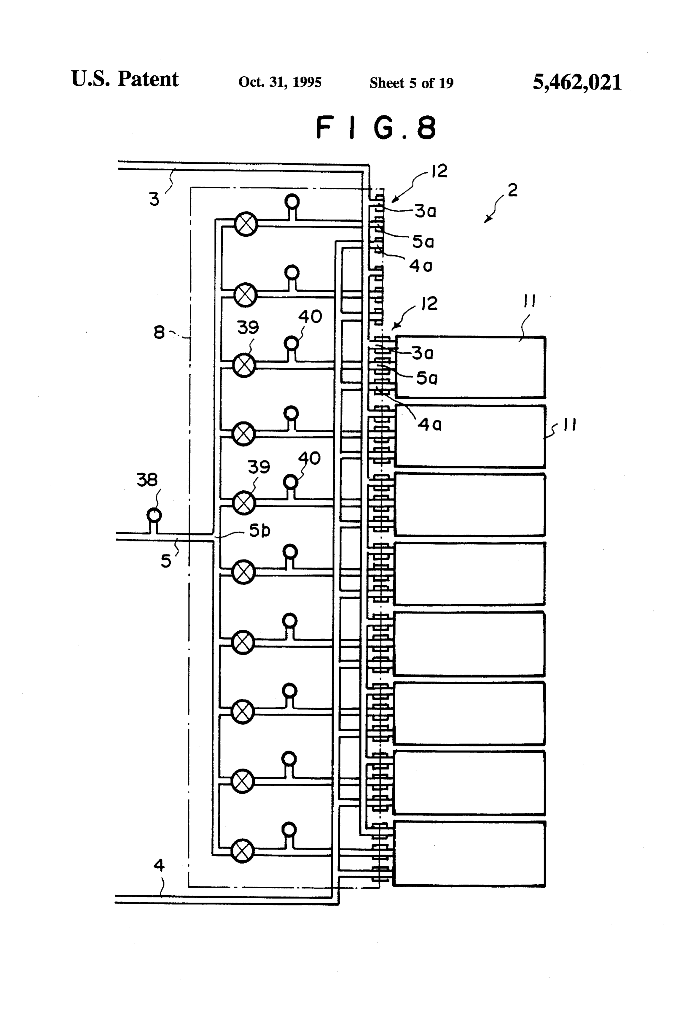
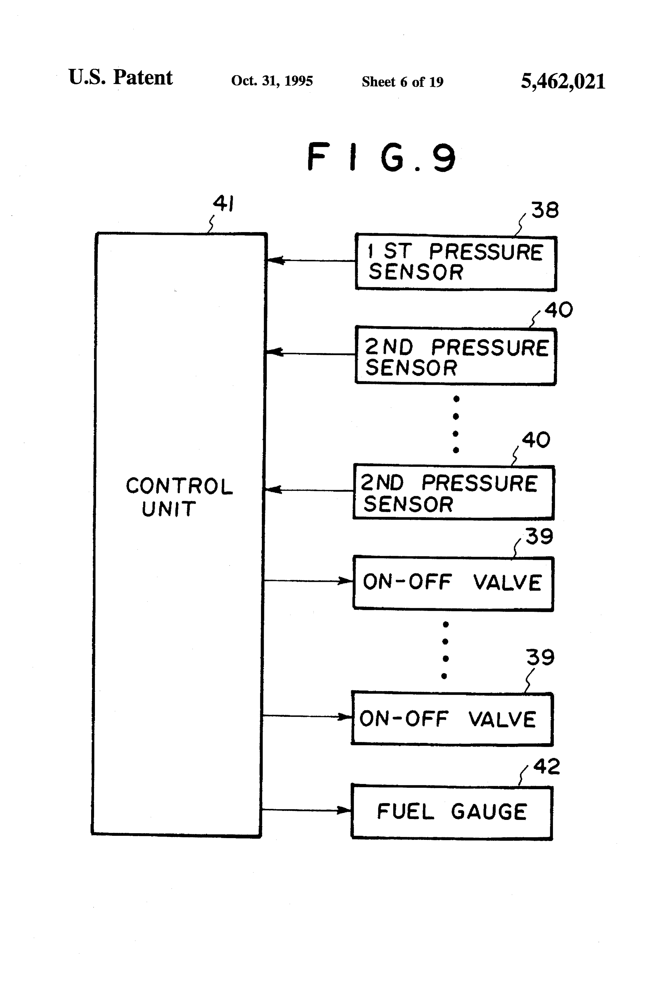
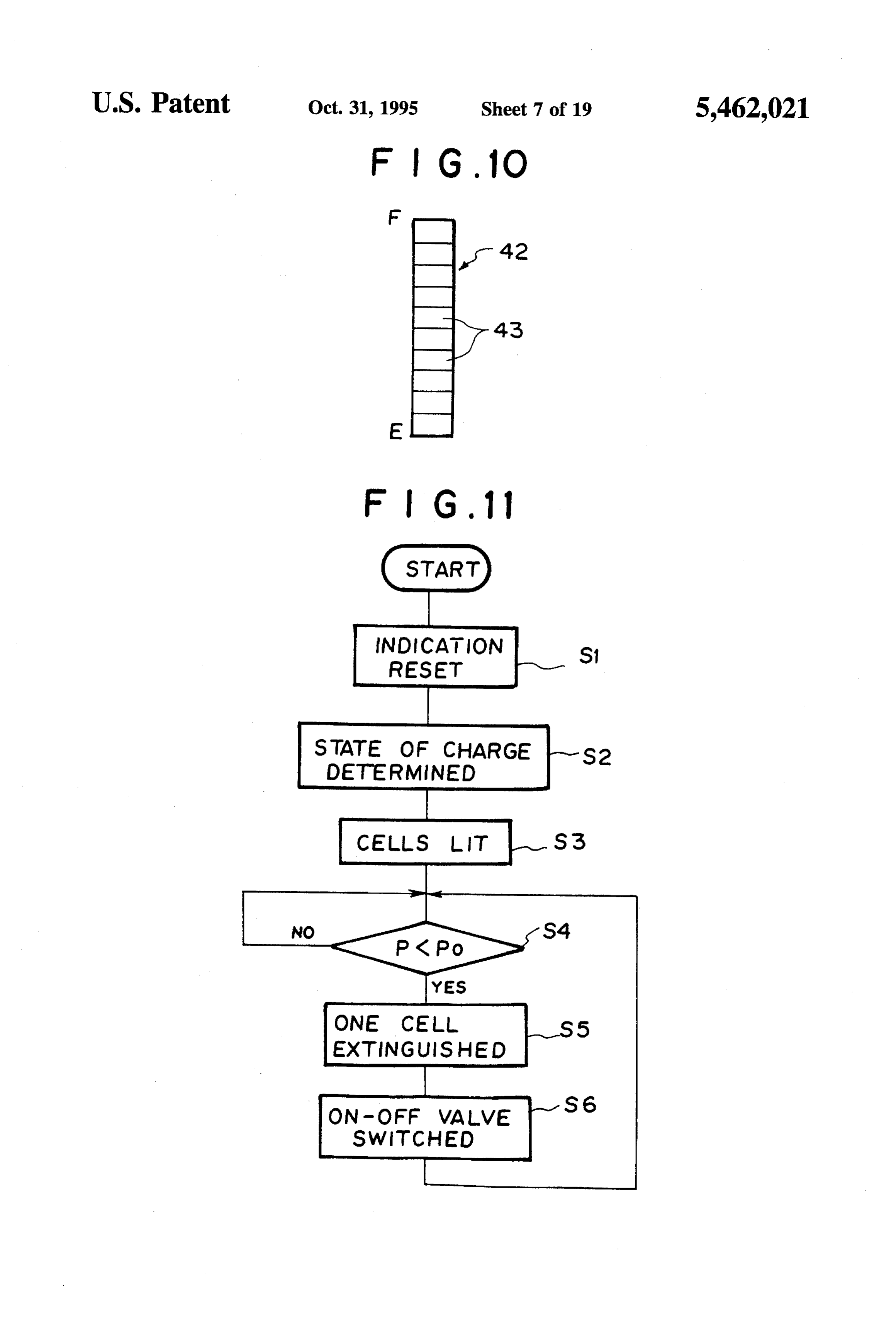
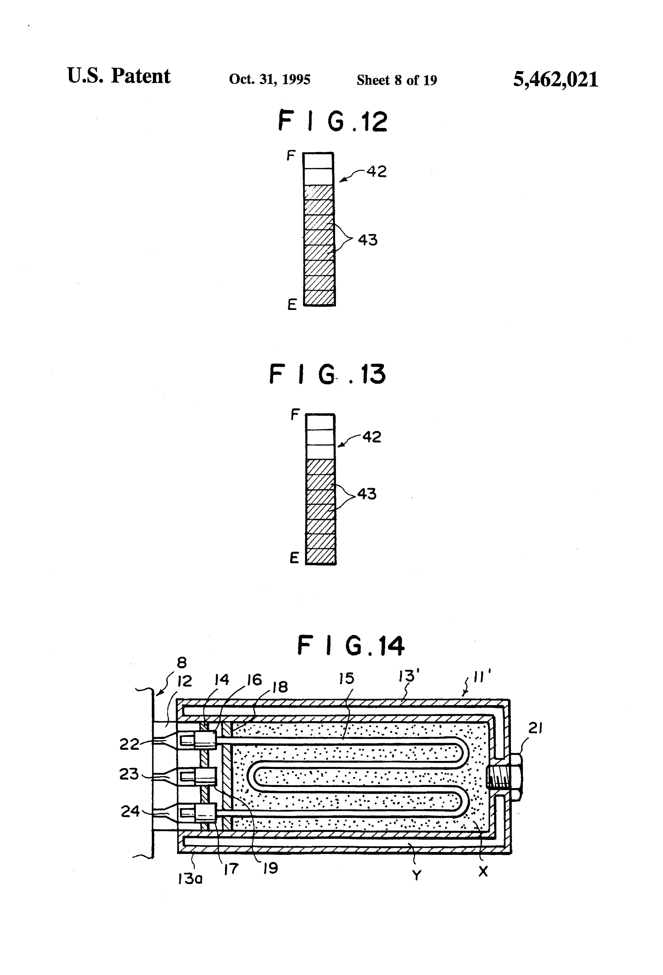
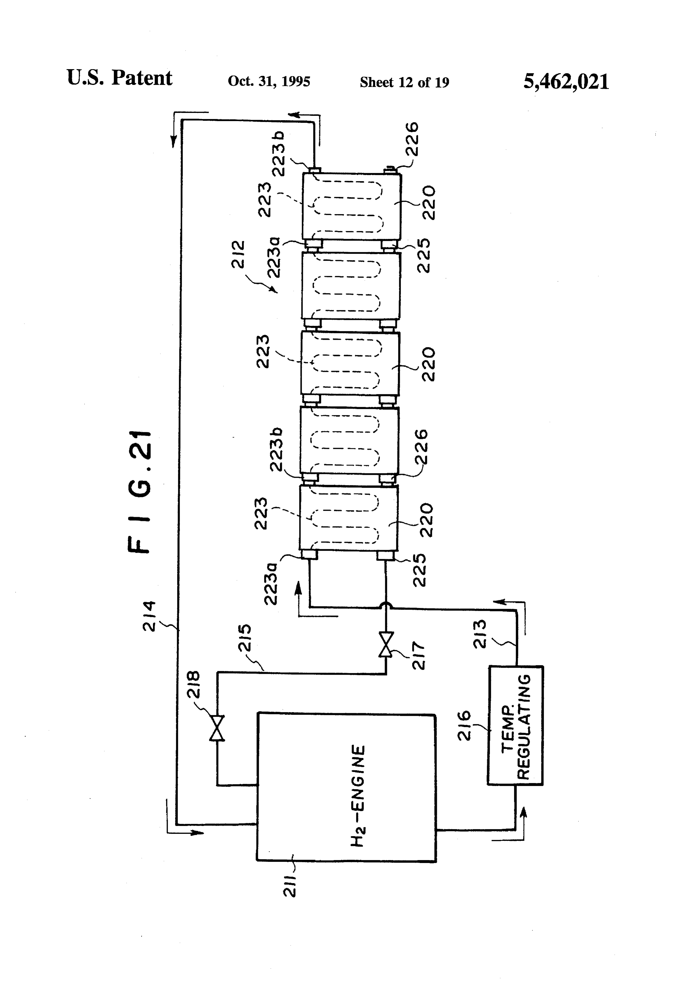
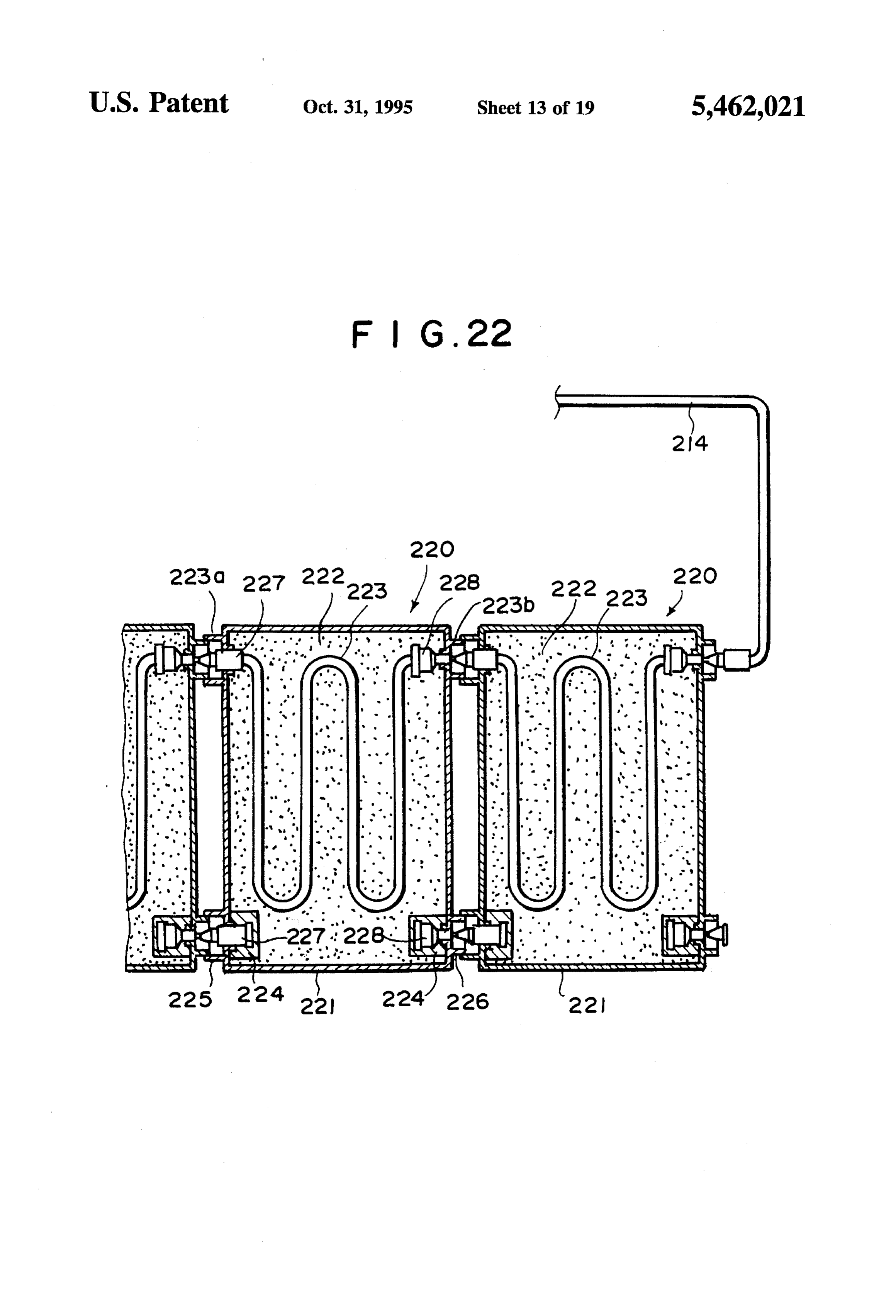
In accordance with one aspect of the present invention, FIG. 1 is a schematic view showing a hydrogen gas there is provided a hydrogen gas supply system for a supply system in accordance with a first embodiment of the hydrogen engine having a hydrogen gas cartridge which is 45 present invention, detachably attached to the engine. The cartridge has a casing FIG. 2 is a schematic plan view showing the hydrogen gas in which hydrogen gas storage alloy and a heating medium storage portion of the first embodiment, passage for heating the hydrogen gas storage alloy are FIG. 3 is a cross-sectional view taken along line A-A in housed. The engine is provided with a hydrogen gas supply FIG. 2, passage which leads hydrogen gas discharged from the 50 FIG. 4 is a cross-sectional view taken along line B-B in hydrogen gas cartridge to the engine, a heating medium FIG. 2, supply passage which supplies heating medium to the heat FIG. 5 is a vertical cross-sectional view showing the fuel ing medium passage in the hydrogen gas cartridge and a heating medium return passage through which the heating cartridge employed in the first embodiment, medium flows out of the hydrogen gas cartridge is returned. FIG. 6 is an enlarged fragmentary cross-sectional view The hydrogen gas cartridge is provided with a hydrogen gas 55 showing the connection between the fuel cartridge and the takeout port, a heating medium inlet and a heating medium connection unit in the first embodiment in the state where the outlet. The hydrogen gas takeout port, the heating medium fuel cartridge and the connection unit are disconnected, inlet and the heating medium outlet are respectively con FIG. 7 is an enlarged fragmentary cross-sectional view nected to and disconnected from the hydrogen gas supply 60 showing the connection between the fuel cartridge and the passage, the heating medium supply passage and the heating connection unit in the first embodiment in the state where the medium return passage in response to attachment and fuel cartridge and the connection unit are connected, detachment of the hydrogen gas cartridge. FIG. 8 is a schematic view showing in more detail the Generally engine coolant is used as the heating medium. hydrogen gas storage portion of the first embodiment, It is preferred that a plurality of hydrogen gas cartridges 65 FIG. 9 is a schematic view showing the control system of which are light in weight and not heavier than 20 Kgfare the hydrogen gas supply system of the first embodiment, detachably attached to the engine. In such a case, though the FIG. 10 is a schematic view showing the fuel gauge,
Page 22
FIG. 11 is a flow chart for illustrating the operation of the are provided between the engine 1 and the hydrogen gas control unit, storage portion 2. The engine coolant supply passage 3 is FIG. 12 is a schematic view showing a state of the fuel provided with a temperature regulating portion 6 which gauge just after the vehicle is replenished with new fuel regulates the temperature of the engine coolant to be intro cartridges, duced into the hydrogen gas storage portion 2. FIG. 13 is a schematic view showing a state of the fuel portion As shown in FIGS. 2 to 4, the hydrogen gas storage gauge after one fuel cartridge is exhausted, 2 comprises a cartridge casing 7 which opens at front and rear ends and a connection unit 8 which is opposed to
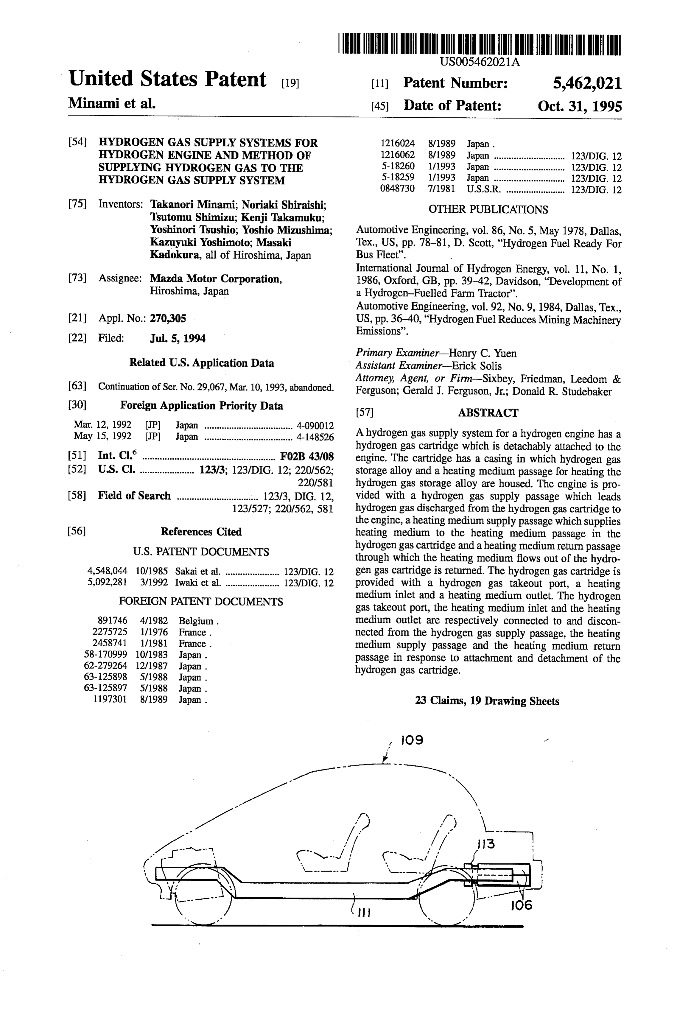
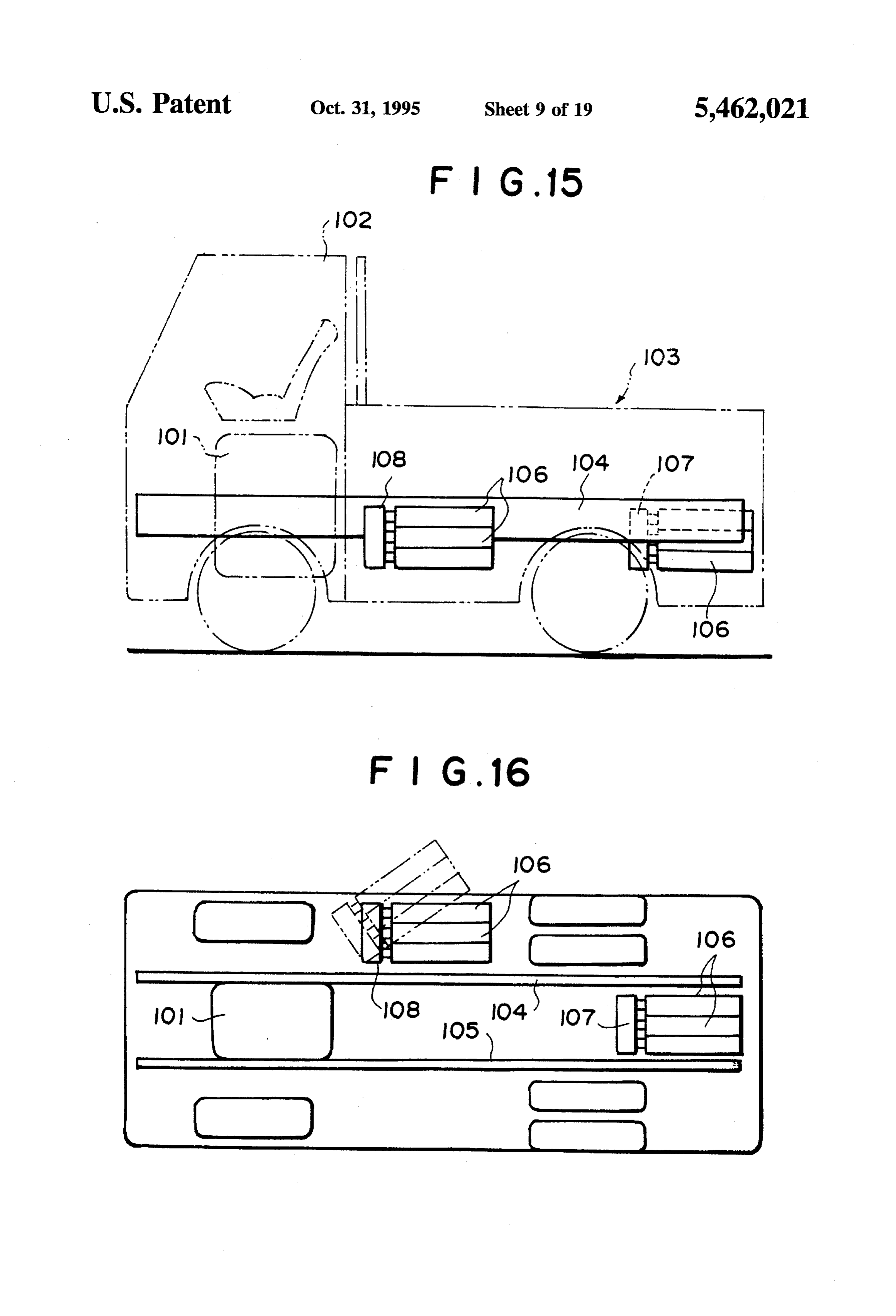
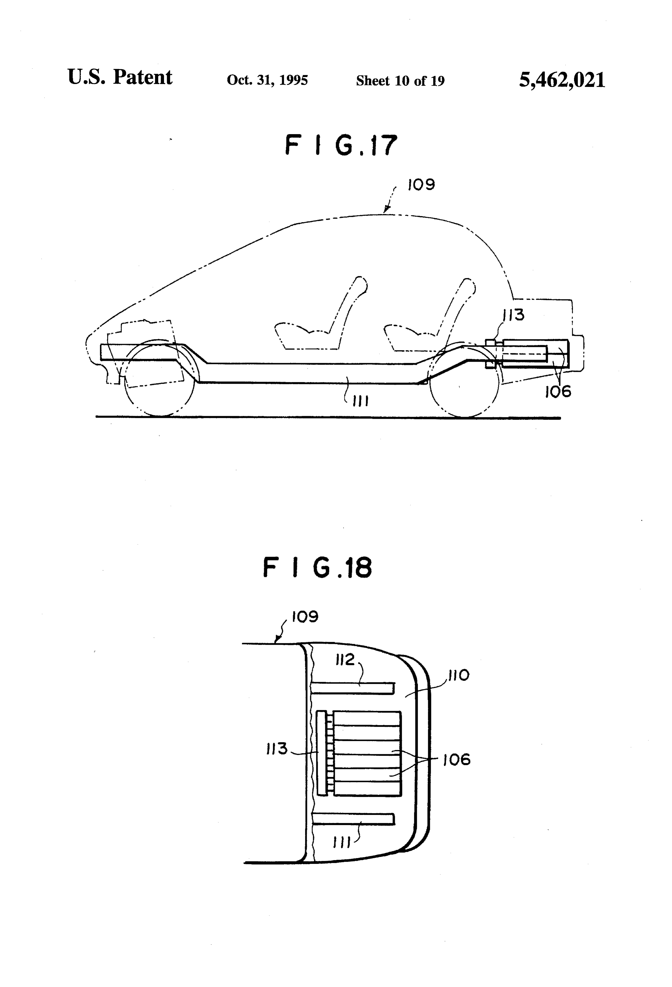
FIG. 14 is a cross-sectional view showing a modification the cartridge casing 7 in front of the same. The connection of the fuel cartridge, 10 unit 8 and the cartridge casing 7 are integrally connected FIG. 15 is a schematic side view of a vehicle showing an with each other by a connecting plate 9. The interior of the example of the manner of mounting the fuel cartridges on cartridge casing 7 is divided by a plurality of partition walls the vehicle, 7a into a plurality of cartridge loading portions 10, and afuel FIG. 16 is a schematic bottom view of the vehicle, cartridge 11 is inserted into each of the cartridge loading FIG. 17 is a schematic side view of a vehicle showing 15 portions 10.
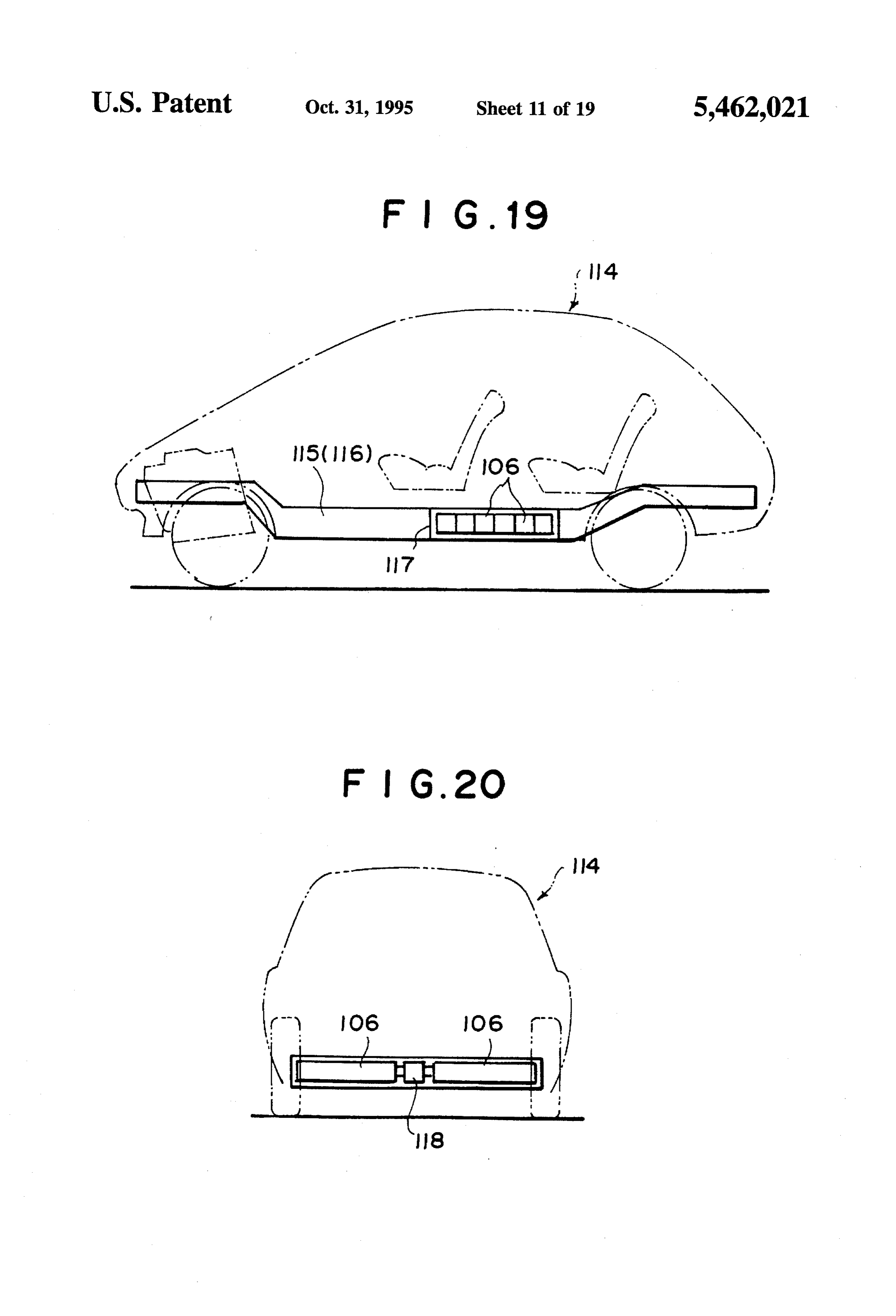
another example of the manner of mounting the fuel car A plurality of joint portions 12 are provided in the tridges on the vehicle, connection unit 8 to project toward the cartridge casing 7 FIG. 18 is a fragmentary plan view showing the rear part engine coolant respective opposed to the supply cartridge loading portions 10. The passage 3, the return passage 4 and of the vehicle with a part of the outer panel of the vehicle 20 the hydrogen gas supply passage 5 are connected to the body removed, connection unit 8.
FIG. 19 is a schematic side view of a vehicle showing still As shown in FIG. 5, each of the fuel cartridges 11 another example of the manner of mounting the fuel car comprises a hollow casing 13 having a front end wall 14 tridges on the vehicle, which is recessed rearward. A twisty conduit 15 is disposed FIG. 20 is a schematic rear view of the vehicle, 25 in the casing 13 and opposite ends of the conduit 15 is FIG. 21 is a schematic view showing a hydrogen gas respectively connected to connectors 16 and 17 which supply system in accordance with a second embodiment of extend through the front end wall 14. A filter 18 for filtering the present invention, hydrogen gas is provided in the casing 13 spaced rearward FIG.22 is a vertical cross-sectional view showing the fuel from the front end wall 14. Another connector 19 extends cartridge employed in the second embodiment, 30 through the front end wall 14 and the inner end of the FIG. 23 is an enlarged fragmentary cross-sectional view connector 19 opens toward the filer 18 between the frontend showing the connection between the fuel cartridges in the wall 14 and the filter 18.
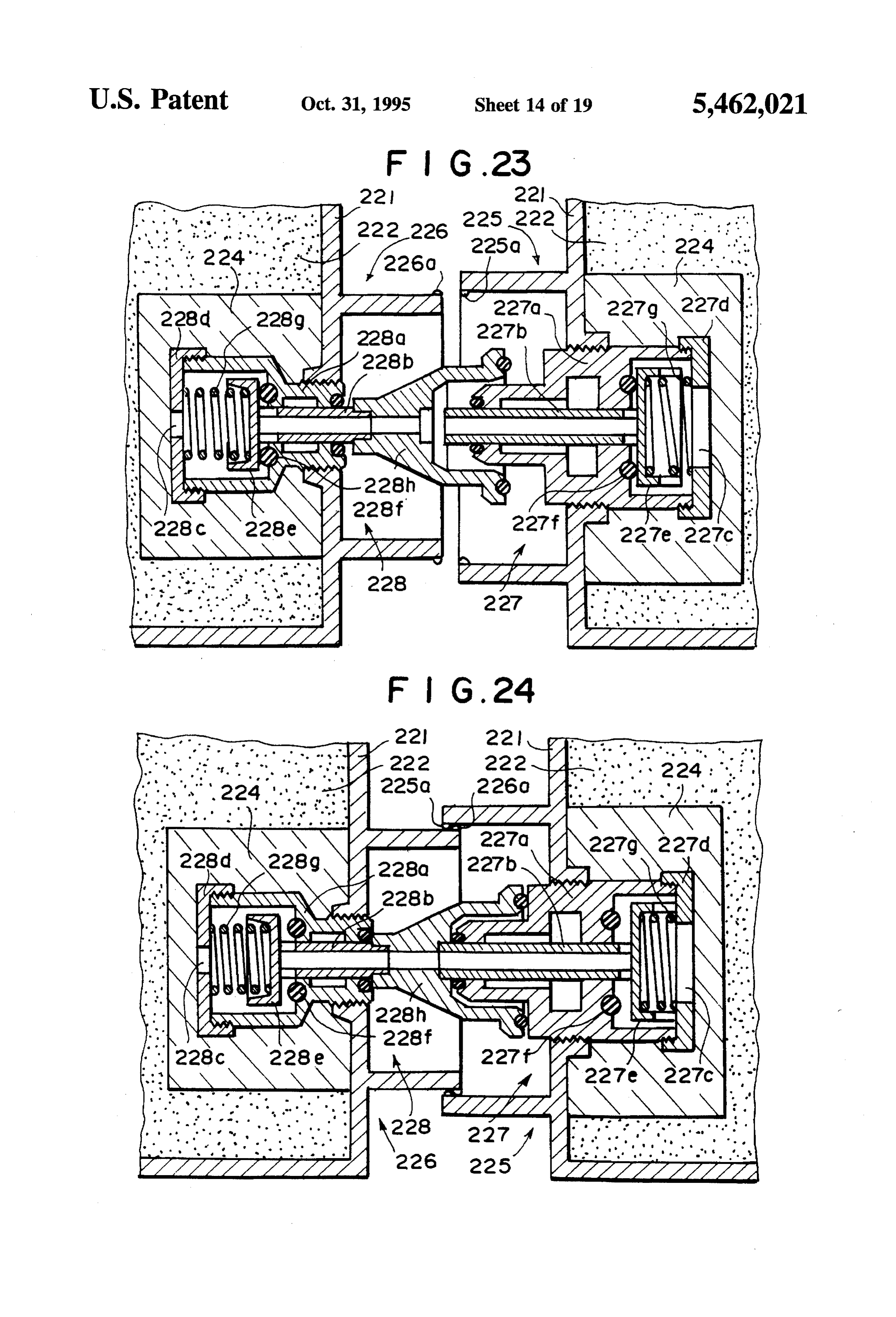
second embodiment in the state where the fuel cartridges are The casing 13 is provided with a rear end wall 20 and a disconnected, 35 hydrogen storage alloy X, which may be, for instance, of
FIG. 24 is an enlarged fragmentary cross-sectional view titanium-manganese alloy, is filled between the rear end wall showing the connection between the fuel cartridges in the 20 and the filter 18. The hydrogen storage alloy X can be second embodiment in the state where the fuel cartridges are changed by removing a plug 21 which is screwed into the connected, rear end wall 20. The total weight of the fuel cartridge 11 should not exceed 20 Kgf and preferably is 10 Kgfor so in
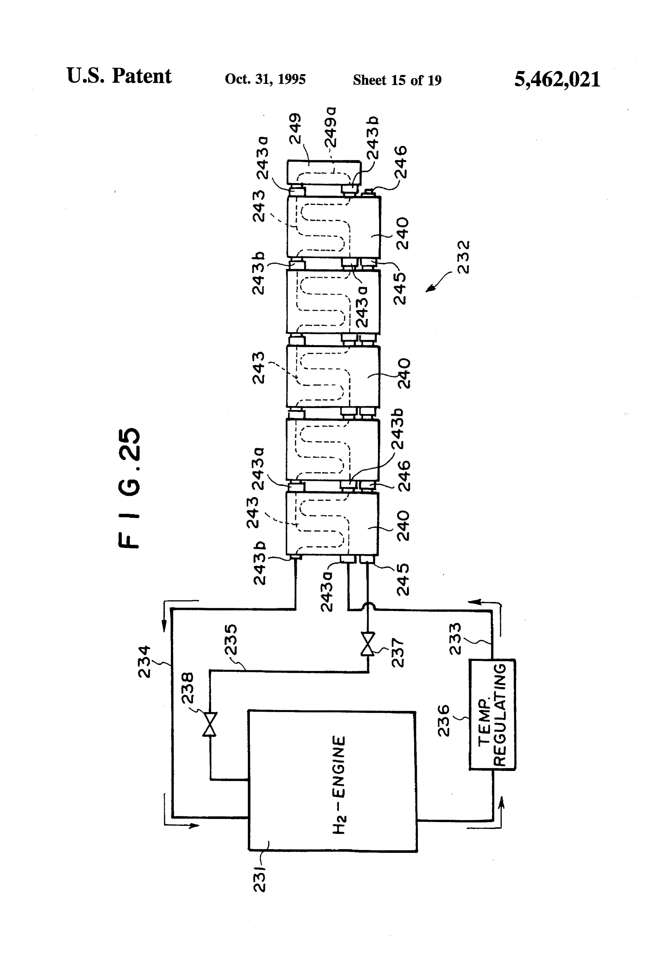
FIG. 25 is a view similar to FIG. 21 but showing a 40 view hydrogen gas supply system in accordance with a third of handling ease.
embodiment of the present invention, When the fuel cartridge 11 is connected to the connection FIG. 26 is an enlarged cross-sectional view showing theunit 8, the front end portion 13a of the casing 13, which fuel cartridges and the communicating member employed in extends forward beyond the front end wall 14, is fitted on the the third embodiment, 45 joint portion 12 of the connection unit 8 and the connectors 16, 17 and 19 are respectively connected to the connectors
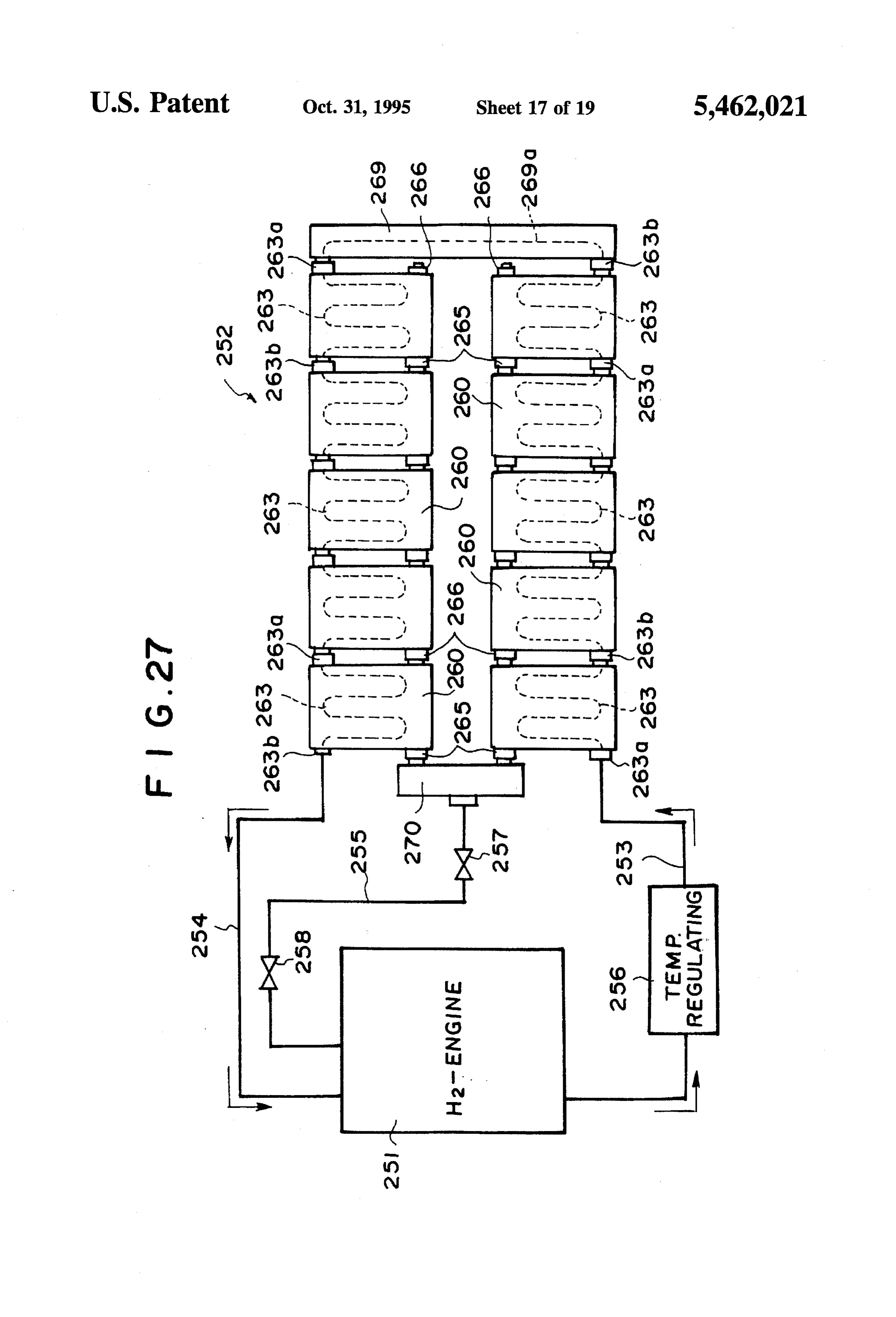
FIG. 27 is a view similar to FIG. 21 but showing a 22, 23 and 24.
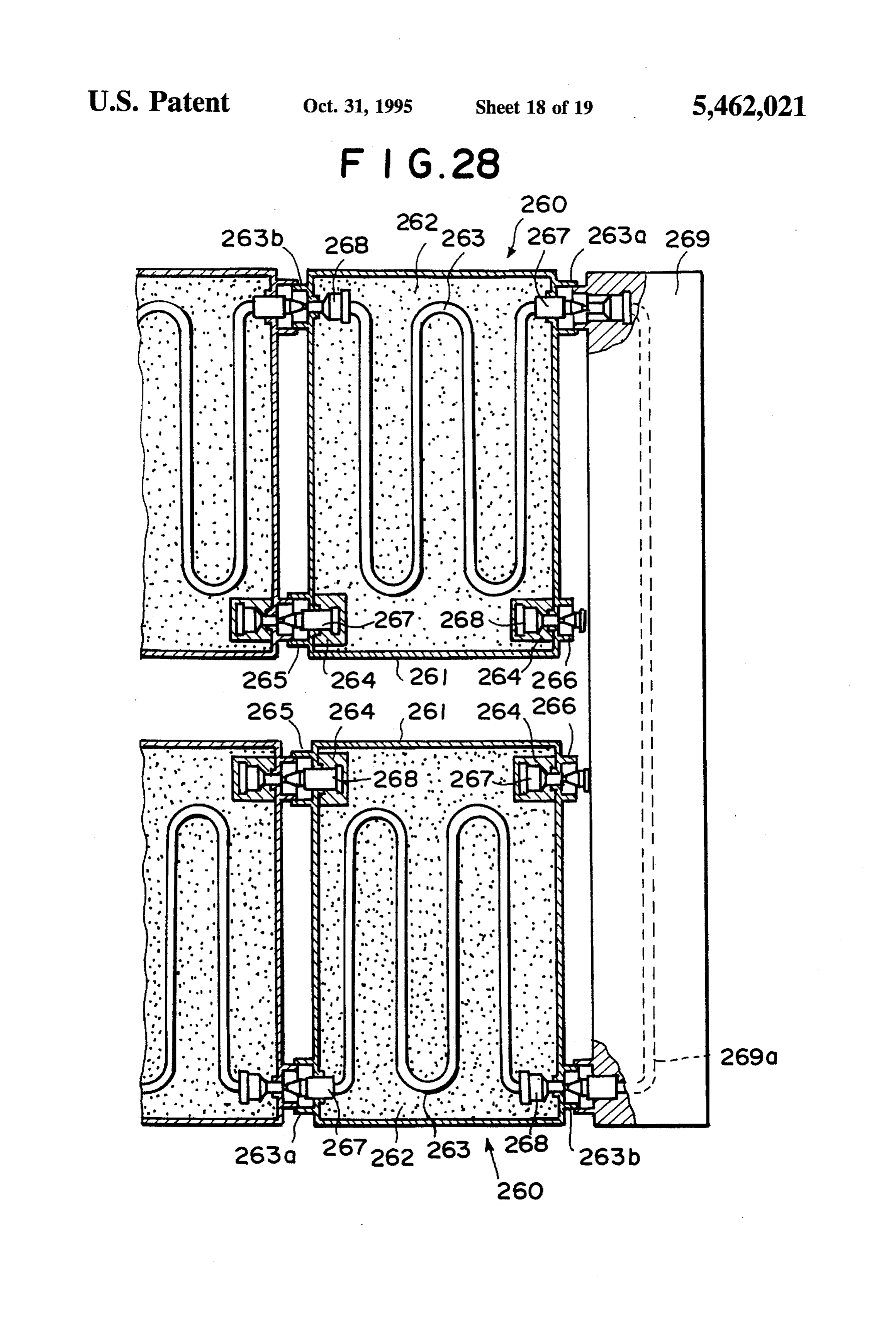
hydrogen gas supply system in accordance with a fourth The structure of the connection between the fuel cartridge embodiment of the present invention, 11 and the connection unit 8 will be described in more detail FIG. 28 is an enlarged cross-sectional view showing the 50 with reference to FIGS. 6 and 7 in conjunction with the fuel cartridges and the communicating member employed in connection between the connectors 19 and 23 by way of the fourth embodiment, and example.
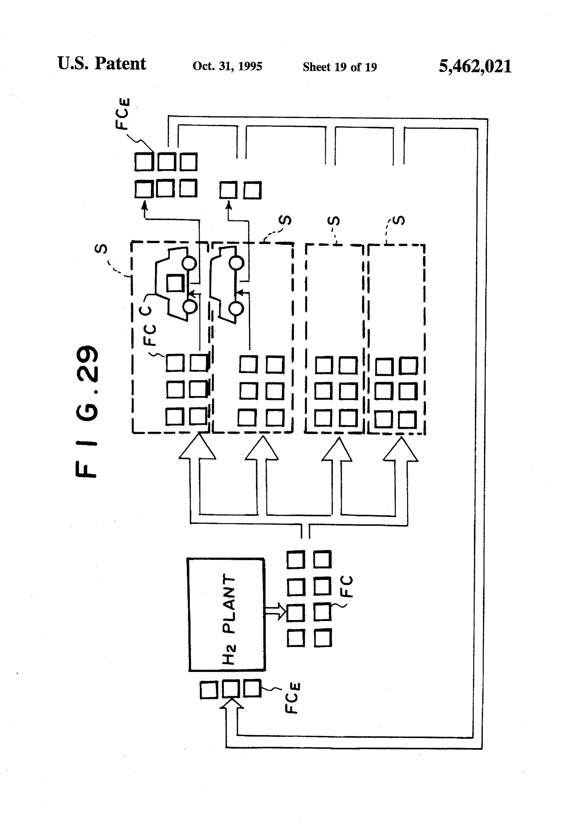
FIG. 29 is a schematic view showing the distribution of The connector 19 through which hydrogen gas in the fuel the fuel cartridges. cartridge 11 is taken out comprises a connector body 19 55 which extends through the front end wall 14, an inner
DESCRIPTION OF THE PREFERRED tubular member 19b which extends through the connector EMBODIMENT body 19a and is slidable relative to the same and a spring retainer 26 which is screwed on the rear end of the connector
In FIG. 1, a hydrogen gas supply system in accordance body 19a and is provided with an opening 25. A valve body with an embodiment of the present invention which is for 60 19c is formed on the rear end of the inner tubular member supplying a hydrogen engine 1 with hydrogen gas has a 19b and is opposed to an O-ring 28 which is provided in a hydrogen gas storage portion 2. An engine coolant supply wall surface in front of the valve body 19c. A return spring passage 3 which leads engine coolant discharged from the 27 is provided between the spring retainer 26 and the valve engine 1 to the hydrogen gas storage portion 2, a return body 19c. and resiliently presses the valve body 19c against passage 4 for returning the engine coolant to the engine 1 65 the O-ring 28.
and a hydrogen gas supply passage 5 which leads hydrogen A tubular support 29 is screwed into a vertical wall gas from the hydrogen gas storage portion 2 to the engine 1 portion 8a of the connection unit 8 at the bottom of the joint
Page 23
portion 12, and a spring retainer 30 is screwed on the rear of pressure signals from the second pressure sensors 40 and end of the support 29. A tubular member 31 extends through causes a fuel gauge 42 to indicate the quantity of the the support 29 and is slidable relative to the same. A remaining hydrogen gas. Further the control unit 41 selec connector body 23b having a recessed portion 23a into tively closes and opens the on-off valves 39 on the basis of which the connector 19 is inserted is fixed to the front end a pressure signal from the first pressure sensor 38. of the tubular member 31. A valve body 31a is formed on the As shown in FIG. 10, the fuel gauge 42 comprises a rear end of the tubular member 31 and is opposed to an plurality of indicator cells 43 which are arranged in a row. O-ring 33 which is provided in a wall surface in front of the The hydrogen gas supply control executed by the control valve body 31a. A return spring 32 is provided between the unit 41 will be described with reference to the flow chart spring retainer 30 and the valve body 31a and resiliently O shown in FIG. 11, hereinbelow.
presses the valve body 31a against the O-ring 33. A branch That is, the control unit 41 resets the indication of the fuel passage 5a communicating with the hydrogen gas supply gauge 42 when the fuel cartridges 11 are changed. (step S1) passage 5 is connected to the spring retainer 30. Then in step S2, the control unit 41 performs a predeter When the fuel cartridge 11 is free, the valve body 19c in mined processing of determining the states of charge of the the fuel cartridge 11 is pressed against the O-ring 28 under 15 respective fuel cartridges 11. That is, the control unit 41 the force of the return spring 27 in the airtight fashion and reads the pressure signals from the respective second pres accordingly the external air cannot enter the fuel cartridge sure sensors 40 and determines whether the pressures of 11, whereby oxidization of the hydrogen storage alloy X is hydrogen gas represented by the pressure signals are higher prevented. than a predetermined reference pressure. The control unit 41 When the fuel cartridge 11 is pushed toward the connec 20 determines that the fuel cartridges 11 corresponding to the tion unit 8, the inner tubular member 19b of the connector pressure signals which represent the pressures higher than 19 is brought into abutment against the bottom of a recess the reference pressure are fully charged. Then the control 23c formed in the connector 23 on the connection unit side, unit 41 opens one of the on-off valves 39 corresponding to and when the connection unit 8 is further pushed toward the the fuel cartridges 11 full of hydrogen gas according to a connection unit 8, the inner tubular member 19b is moved 25 predetermined order.
rightward relative to the connector body 19b overcoming the Thereafter the control unit 41 lights the same number of force of the return spring 27 and the tubular member 31 indicator cells 43 as the number of the fuel cartridges 11 full together with the connector body 23b is moved leftward of hydrogen gas. For example, when eight fuel cartridges 11 relative to the support 29 overcoming the force of the return full of hydrogen gas are connected to the joint portions 12, spring 32. Thus in the state whether the fuel cartridge 11 has 30 the control unit 41 lights the eight indicator cells 43 from the been completely pushed toward the connection unit 8, the lowermost one as shown in FIG. 12 (hatched portion). opening 25 of the connector 19 on the fuel cartridge side Then is step S41, the control unit 41 repeatedly deter communicates with the branch passage 5a by way of the mines whether the pressure P represented by the pressure tubular members 19b and 31 as shown in FIG. 7. signal from the first pressure sensor 38 is lower than a As shown in FIGS. 2 and 3, a lid 34 is hinged to the rear 35 reference value Po until the former becomes lower than the end of the cartridge casing 7 at its lower edge. Engagement latter. When the pressure P represented by the pressure members 35 fixed to the upper edge of the lid 34 are engaged signal from the first pressure sensor 38 becomes lower than with engagement members 36 fixed to the upper surface of the reference value Po, the control unit 41 extinguishes the the cartridge casing 7 when the lid 34 is closed and hold the 40 uppermost one of the indicator cells 43 which has been lit as lid 34 in the closed position. In the closed position, a leaf shown in FIG. 13. (step S5) Then is step S6, the control unit spring 37 on the inner surface of the lid 34 resiliently pushes 41 closes the on-off valve 39 which has been opened and the fuel cartridges 11 toward the connection unit 8. opens the on-off valve 39 corresponding to another of the As shown in FIG. 8, each of the joint portions 12 is fuel cartridges 11 full of hydrogen gas. Thus the number of provided with branch passages 3a, 4a and 5a which respec 45 the lighted indicator cells 43 reflects the number of the fuel tively communicate with the engine coolant supply passage cartridges 11 full of hydrogen gas and accordingly the 3, the return passage 4 and the hydrogen gas supply passage remaining nized.
quantity of hydrogen gas can be surely recog 5. The engine coolant at a regulated temperature flows through the engine coolant supply passage 3, the conduit 15 As can be understood from the description above, in this in each fuel cartridge 11 and the return passage 4 and heats 50 embodiment, since the fuel cartridges 11 are removably the hydrogen storage alloy X, whereby the hydrogen storage attached to the hydrogen gas supply passage 5, the engine 1 alloy X discharges hydrogen gas, which flows into the can be replenished with hydrogen gas only by replacing the hydrogen gas supply passage 5 through the branch passage exhausted fuel cartridges 11 with new fuel cartridges 11 full 5a. of hydrogen gas.
The branch passages 5a are merged into the hydrogen gas 55 FIG. 14 shows a modification of the fuel cartridge 11. The supply passage 5 at a junction 5b. A first pressure sensor 38 fuel cartridge 11' of this modification differs from the fuel is provided in the hydrogen gas supply passage 5 down cartridge 11 shown in FIG. 5 in that the casing 13' has a stream of the junction 5b. On-off valves 39 are provided in double wall structure comprising inner and outer walls, and the branch passages 5a to open and close the respective the space between the inner and outer walls is filled with branch passages 5a. Second pressure sensors 40 are pro 60 water Y. This structure is advantageous in that the hydrogen vided in the respective branch passages. 5a upstream of the storage alloy X is rapidly cooled by the water Y in case on-off valves 39 and detect the pressures of the hydrogen gas where the fuel cartridge 11' is broken while the hydrogen discharged from the respective fuel cartridges 11. storage alloy X is at a high temperature, thereby preventing The hydrogen gas supply system of this embodiment is an accidental hydrogen gas leak.
further provided with an electronic control unit 41 as shown 65 The hydrogen gas supply system of the present invention in FIG. 9. The control unit 41 determines the quantities of can be mounted on a vehicle in the following manner. hydrogen gas in the respective fuel cartridges 11 on the basis For example, as shown in FIGS. 15 and 16, in the case of
Page 24
a cab-over type vehicle in which a cabin 102 is positioned diate fuel cartridges 220 is connected to the outlet 223b of above an engine 101, a connection unit 107 is provided the fuel cartridge 220 adjacent thereto on the upstream side between a pair of side frames 104 and 105 near the rear end and the outlet 223b of each of the intermediate fuel car of a vehicle body 103 and another connection unit 108 is tridges 220 is connected to the inlet 223b of the fuel provided on the outer side of the side frame 104 with cartridge 220 adjacent thereto on the downstream side. Thus connection units being exposed downward. Reference the engine coolant passages 223 of the fuel cartridges 220 numeral 106 denotes a fuel cartridge. The connection unit are connected in series to the engine coolant supply passage 108 is mounted to be swung outward as shown by the 213 and the return passage 214.
chained line in FIG. 16 and the fuel cartridges 106 are A hydrogen gas takeout port 225 communicating with the changed with the connection unit 108 in the swung position. 10 hydrogenstorage alloy 222 by way of a filter 224 is provided In the case of a sedan type vehicle, a connection unit 113 on a lower part of the front end wall of the casing 221 and is provided between side frames 111 and 112 below a trunk a connection port 226 also communicating with the hydro 110 on the rear of the vehicle to extend in the transverse gen storage alloy 222 by way of a filter 224 is provided on direction of the vehicle body as shown in FIGS. 17 and 18. a lower part of the rear end wall of the casing 221. The connection port 226 of each of the intermediate fuel car
In the example shown in FIGS. 19 and 20, an opening 117 15 tridges is provided in each of side frames 115 and 166 extending in 225 of220 are connected to the hydrogen gas takeout port the longitudinal direction of the vehicle body and a connec upstream side.fuel cartridge 220 adjacent thereto on the the tion unit 118 is provided to extend in the longitudinal Since the connection between the inlet 223a and the outlet direction of the vehicle body between the side frames 115 and 116. In this case, the fuel cartridges 106 are connected 20 223b of the engine coolant passages 223 are the same in to the connection unit 118 from opposite sides of the vehicle structure as the connection between the hydrogen gas take body as clearly shown in FIG. 20. Accordingly more num out port 225 and the connection port 226 of the adjacent fuel bers of fuel cartridges 106 can be mounted. cartridges 220, only the latter connection will be described In the embodiment described above, the conduits for hereinbelow. As shown in FIGS. 23 and and 24, the hydro circulating the engine coolant through the respective fuel 25 gen gas takeout port 225 is provided with a connector 227 and the connection port 226 is provided with a connector cartridges 11 are connected to the engine coolant supply 228. The connector 227 comprises a connector body 227a passage in parallel to each other. This arrangement can give rise to a problem that the engine coolant cannot be uniformly mounted 227b which on the casing 221 and an inner tubular member extends through the connector body 227a and is distributed to all the fuel cartridges 11. When the engine slidable relative to the same. A spring retainer 227d provided coolant is not uniformly distributed to the fuel cartridges 11, 30 with an opening 227c is screwed on the rear end of the the hydrogen gas stored in the fuel cartridges 11 is unevenly connector body 227a and is in contact with the filter 224. A consumed.
valve body 227e is formed on the rear end of the inner
In a second embodiment of the present invention shown tubular member 227b and is opposed to an O-ring 227f in FIG. 21, the conduits for circulating the engine coolant 35 which is provided in a wall surface in front of the valve body through the respective fuel cartridges 11 are connected to the 227e. A return spring 227g is provided between the spring engine coolant supply passage in series. retainer 227d and the valve body 227e and resiliently presses In FIG. 21, the hydrogen gas supply system for a hydro the valve body 227e against the O-ring 227f gen engine 211 has a hydrogen gas storage portion 212. An The connector 228 comprises a connector body 228a engine coolant supply passage 213 which leads engine 40 mounted on the casing 221 and an inner tubular member coolant discharged from the engine 211 to the hydrogen gas 228b which extends through the connector body 228a and is storage portion 212, a return passage 214 for returning the slidable relative to the same. A spring retainer 228d provided engine coolant to the engine 211 and a hydrogen gas supply with an opening 228c is screwed on the rear end of the passage 215 which leads hydrogen gas from the hydrogen connector gas storage portion 212 to the engine 211 are provided 45 valve bodybody 228e 228a and is in contact with the filter 224. A is formed on the rear end of the inner between the engine 211 and the hydrogen gas storage tubular member 228b and is opposed to an O-ring 228f portion 212. The engine coolant supply passage 213 is which is provided in a wall provided with a temperature regulating portion 216 which 228e. A return spring 228gsurface in front of the valve body is provided between the spring regulates the temperature of the engine coolant to be intro retainer 228d and the valve body 228e and resiliently presses duced into the hydrogen gas storage portion 212. The hydrogen gas supply passage 215 is provided with a pair of 50 the head valve body 228e against the O-ring 228f A connector 228h having a recessed portion into which the frontend on-off valves 217 and 218. portion of the inner tubular member 227b of the connector In the hydrogen gas storage portion 212, there are pro 227 is inserted is fixed to the front end of the inner tubular vided a plurality of fuel cartridges 220 arranged in a row. member 228b. When the connectors 227 and 228 are dis As shown in FIG. 22, each fuel cartridge 220 comprises 55 connected, the valve bodies 227e and 228e are respectively a casing 221 and a hydrogen storage alloy 222 which may pressed against the O-rings 227 fand 228funder the force of be, for instance, of titanium-manganese alloy, housed in the the return springs 227g and 228g in the airtight fashion as casing 221. A twisty engine coolant passage 223 extends shown in FIG. 23 and accordingly the external air cannot through the hydrogen storage alloy 222 and an inlet 223a enter the fuel cartridges 221, whereby oxidization of the and an outlet 223b of the engine coolant passage 223 are 60 hydrogen storage alloys 222 is prevented, and at the same provided respectively on upper parts of front and rear end time the hydrogen gas cannot leak out of the fuel cartridge walls of the casing 221. The inlet 223a of the upstream-most 220.
(leftmost as seen in FIG. 21) fuel cartridge 220 is connected When the connectors 227 and 228 are moved toward each to the end of the engine coolant supply passage 213 and the other to connect them, the front end of the inner tubular outlet 223b of the downstream-most (rightmost as seen in 65 member 227b of the connector 227 is brought into abutment FIG. 21) fuel cartridge 220 is connected to the end of the against the connector head 228h of the other connector 228 return passage 214. The inlet 223a of each of the interme and the valve bodies 227e and 228e are moved away from
Page 25
the O-rings 227 fand 228fovercoming the force of the return hydrogen gas supply passage 235 is provided with a pair of springs 227g and 228g, whereby the openings 227c and 228c on-off valves 237 and 238.
in the spring retainers 227d and 228d comes to communicate In the hydrogen gas storage portion 232, there are pro with each other through the inner tubular members 227b and vided a plurality of fuel cartridges 240 arranged in a row. 228b and the hydrogen storage alloys 222 in the fuel As shown in FIG. 26, each fuel cartridge 240 comprises cartridges 220 are communicated with each other. a casing 241 and a hydrogen storage alloy 242 which may When the connectors 227 and 228 are connected to each other, the hydrogen gas takeout port 225 is fitted on the be, for instance, of titanium-manganese alloy, housed in the casing 241. A pair of twisty engine coolant passages 243 connection port 226 and an engagement projection 225a extend formed on the inner peripheral surface of the hydrogen gas 10 243a andthrough the hydrogen storage alloy 242 and inlets outlets 243b of the engine coolant passages 243 are takeout port 225 is engaged with an engagement projection provided 226a formed on the inner peripheral surface of the connec inlet 243aonof frontone and rear end walls of the casing 241, the of the engine coolant passages 243 and the tion port 226 as shown in FIG. 24, whereby the adjacent fuel outlet 243b of the other engine coolant passage 243 on the cartridges 220 are fixed to each other, frontend wall and the outlet 243b of said one engine coolant The engine coolant passages 223 in the adjacent fuel 15 passage 243 and the inlet 243a of said the other engine cartridges 220 are connected through the same structure, and coolant passage the engine coolant passages 223 in the respective fuel takeout port 245 243 on the rear end wall. A hydrogen gas communicating with the hydrogen storage cartridges 220 are connected in series between the engine coolant supply passage 213 and the return passage 214. The alloy wall 242 by way of a filter 244 is provided on the front end of the casing 241 and a connection port 246 also hydrogen storage alloys 222 in the fuel cartridges 220 are 20 communicating with the hydrogen storage alloy 242 by way heated by the engine coolant which circulates between the of a filter 244 is provided on the rear end wall of the casing engine 211 and the fuel cartridges 220 through the engine 241. The connection coolant supply passage 213 and the return passage 214 and 240 is connected to theport 246 of each of the fuel cartridges hydrogen gas discharged from the hydrogen storage alloys fuel cartridge 240 adjacent theretogasontakeout hydrogen the port 245 of the upstream side.
222 is supplied to the hydrogen gas supply passage 215. 25 As shown in FIGS. 25 and 26, a communicating member With the arrangement described above, since the engine 249 is connected to the rightmost fuel cartridge 240 to coolant passages 223 in the fuel cartridges 220 are con connect the outlet 243b of one of the engine coolant pas nected in series, the engine coolant is uniformly supplied to all the fuel cartridges 220 without stagnancy of the engine 243a of theofother sages 243 the rightmost fuel cartridge 240 to the inlet engine coolant passage 243 of the same coolant which is apt to occur when the engine coolant 30 fuel cartridge 240 by way of a communicating passage 249a passages 223 are connected in parallel to each other, whereby the hydrogen gas stored in the fuel cartridges 220 formed in the communicating member 249. The connections between the engine coolant supply pas can be uniformly consumed.
sage 233 and the inlet 243a of one of the engine coolant
Further since the outlet 223b of the engine coolant pas 35 passage 243 of the leftmost fuel cartridge 240, between the sage 223 of each fuel cartridge 220 is directly connected to the inlet 223a of the engine coolant passage 223 of another coolant passage234243andofthetheoutlet return passage 243b of the other engine leftmost fuel cartridge 240, fuel cartridge 220, the overall connection structure is sim between the outlet 243b and inlet 243a of the engine coolant plified as compared with a case where the outlet 223b and passages 243 of the rightmost fuel cartridge 240 and the the inlet 223a of the adjacent fuel cartridges 220 are con 40 communicating passage 249a in the communicating mem nected through a communicating member. At the same time, the number of the fuel cartridges 220 can be easily changed ber 249, between the outlets 243b and the inlet 243a of adjacent intermediate fuel cartridges 240, and between the depending on the expected running distance and/or the connection port 246 and the hydrogen gas takeout port 245 expected running condition, whereby mounting ease and of the adjacent fuel cartridges 240 are made by connectors handling ease of the fuel cartridges 220 are improved. 45 247 and 248 which are the same in structure as the connec Further since the hydrogen gas takeout port 225 and the tors 227 and 228 described above.
connection port 226 of each fuel cartridge 220 are automati With the arrangement described above, since one engine cally opened and closed in response to connection and coolant passages 243 in the respective fuel cartridges 240 disconnection of the connectors 227 and 228, connection and disconnection of the hydrogen gas takeout port 225 and 50 243 connected are in series, the other engine coolant passages in the respective fuel cartridges 240 are connected in the connection port 226 can be effected very easily and very series and the passages formed by said one engine coolant surely. passages 243 and said the other engine coolant passages 243 Now a third embodiment of the present invention will be are connected in series by the communicating passage 249a described with reference to FIGS. 25 and 26, hereinbelow. in the communicating member 249, a continuous engine In FIG. 25, the hydrogen gas supply system for a hydro 55 coolant passage through which the engine coolant flows in gen engine 231 has a hydrogen gas storage portion 232. An one direction and in the reverse direction is formed. Accord engine coolant supply passage 233 which leads engine ingly, as in the second embodiment, the engine coolant is coolant discharged from the engine 231 to the hydrogen gas uniformly supplied to all the fuel cartridges 240 without storage portion 232, a return passage 234 for returning the stagnancy of the engine coolant which is apt to occur when engine coolant to the engine 231 and a hydrogen gas supply the engine coolant passages 243 are connected in parallel to passage 235 which leads hydrogen gas from the hydrogen each other, whereby the hydrogen gas stored in the fuel gas storage portion 232 to the engine 231 are provided cartridges 240 can be uniformly consumed. between the engine 231 and the hydrogen gas storage Further since the outlet 243b of the engine coolant pas portion 232. The engine coolant supply passage 233 is sage 243 of each fuel cartridge 240 is directly connected to provided with a temperature regulating portion 236 which 65 the inlet 243a of the engine coolant passage 243 of another regulates the temperature of the engine coolant to be intro fuel cartridge 240 as in the second embodiment, the overall duced into the hydrogen gas storage portion 232. The connection structure is simplified as compared with a case
Page 26
where the outlet 243b and the inlet 243a of the adjacent fuel nected to the hydrogen gas supply passage 255 by way of a cartridges are connected through a communicating member. communicating member 270.
At the same time, the number of the fuel cartridges 240 can The connections between the respective parts are made by be easily changed depending on the expected running dis connectors 267 and 268 which are the same in structure as tance and/or the expected running condition, whereby the connectors 227 and 228 described above.
mounting ease and handling ease of the fuel cartridges 240 With the arrangement described above, the engine coolant are improved. passages 263 in the respective fuel cartridges 260 in each of Further since the hydrogen gas takeout port 245 and the the upper and lower rows are connected in series, and the connection port 246 of each fuel cartridge 240 are automati passages respectively formed by the engine coolant passages cally opened and closed in response to connection and 10 263 in the fuel cartridges 260 in the upper and lower rows disconnection of the connectors 247 and 248, connection are connected in series by the communicating member 269. and disconnection of the hydrogen gas takeout port 245 and Accordingly, as in the second and third embodiments, the the connection port 246 can be effected very easily and very engine coolant is uniformly supplied to all the fuel cartridges Surely. 260 without stagnancy of the engine coolant which is apt to Now a fourth embodiment of the present invention will be 15 occur when the engine coolant passages 263 are connected described with reference to FIGS. 27 and 28, hereinbelow. in parallel to each other, whereby the hydrogen gas stored in In FIG. 27, the hydrogen gas supply system for a hydro the fuel cartridges 260 can be uniformly consumed. gen engine 251 has a hydrogen gas storage portion 252. An Further since the outlet 263b of the engine coolant pas engine coolant supply passage 253 which leads engine 20 sage 263 of each fuel cartridge 260 is directly connected to coolant discharged from the engine 251 to the hydrogen gas the inlet 263a of the engine coolant passage 263 of another storage portion 252, a return passage 254 for returning the fuel cartridge 240 as in the second and third embodiment, engine coolant to the engine 251 and a hydrogen gas supply the overall connection structure is simplified as compared passage 255 which leads hydrogen gas from the hydrogen with a case where the outlet 263b and the inlet 263a of the gas storage portion 252 to the engine 251 are provided adjacent fuel cartridges are connected through a communi between the engine 251 and the hydrogen gas storage 25 cating member. At the same time, the number of the fuel portion 252. The engine coolant supply passage 253 is cartridges 260 can be easily changed depending on the provided with a temperature regulating portion 256 which expected running distance and/or the expected running con regulates the temperature of the engine coolant to be intro dition, whereby mounting ease and handling ease of the fuel duced into the hydrogen gas storage portion 252. The 30 cartridges 260 are improved.
hydrogen gas supply passage 255 is provided with a pair of Further since the hydrogen gas takeout port 265 and the on-off valves 257 and 258. connection port 266 of each fuel cartridge 260 are automati In the hydrogen gas storage portion 252, there are pro cally opened and closed in response to connection and vided a plurality of fuel cartridges 260 arranged in two rows. disconnection of the connectors 267 and 268, connection As shown in FIG. 28, each fuel cartridge 260 comprises 35 the and disconnection of the hydrogen gas takeout port 265 and a casing 261 and a hydrogen storage alloy 242 which may surely. connection port 266 can be effected very easily and very be, for instance, of titanium-manganese alloy, housed in the casing 261. A twisty engine coolant passage 263 extends Though, in the second to fourth embodiments, not only through the hydrogen storage alloy 262 and an inlets 263a. the engine coolant passages but also the hydrogen gas and an outlet 263b of the engine coolant passages 263 are 40 takeout ports are connected in series, the hydrogen gas provided respectively on front and rear end walls of the takeout ports of the respective fuel cartridges may be casing 261. A hydrogen gas takeout port 265 communicating connected to the hydrogen gas supply passage in parallel to with the hydrogen storage alloy 262 by way of a filter 264 each other by way of branch passages. In such a case, by is provided on the front end wall of the casing 261 and a providing an on-off valve in each of the branch passages, connection port 256 also communicating with the hydrogen 45 hydrogen gas can be taken out from a desired one of the fuel storage alloy 262 by way of a filter 264 is provided on the cartridges.
rear end wall of the casing 261. The connection port 266 of In all the first to fourth embodiments described above, the each of the fuel cartridges 260 is connected to the hydrogen engine coolant supply passage, the return passage and the gas takeout port 265 of the fuel cartridge 260 adjacent engine coolant passages in the fuel cartridges are automati thereto on the upstream side. 50 cally closed when any one or more of the fuel cartridges is The inlet 263a of the engine coolant passage 263 of the disconnected. Accordingly there is no possibility of engine leftmost fuel cartridge 260 in the lower row (as seen in FIG. coolant leaking out. This is especially advantageous when 27) is connected to the engine coolant supply passage 253 the engine coolant is used as heating medium for the and the outlet 263b of the engine coolant passage 263 of the hydrogen storage alloy.
leftmost fuel cartridge 260 in the upper row is connected to 55 For example, the vehicle provided with the hydrogen gas the return passage 254. Further the outlet 263b of the supply system of this embodiment can be replenished with rightmost fuel cartridge 260 in the lower row is connected to hydrogen gas in the following manner. the inlet 263a of the rightmost fuel cartridge 260 in upper In FIG. 29, hydrogen gas produced in a hydrogen gas row by way of a communicating passage 269a formed in a plant is stored in the hydrogen storage alloy in fuel car communicating member 269. That is, the engine coolant 60 tridges FC, and the fuel cartridges FC filled with hydrogen supplied from the engine coolant supply passage 253 flows gas are transported to filling stations S. Since the hydrogen through the engine coolant passages 263 of the fuel car gas stored in the hydrogen storage alloy cannot be dis tridges 260 in the lower row, the communicating passage charged unless it is heated, the fuel cartridges FC can be 269 and the engine coolant passages 263 of the fuel car handled in the same manner as general freight and can be tridges 260 in the upper row to the return passage 254. 65 transported without use of specialized facilities unlike the Further the hydrogen gas takeout ports 265 of the leftmost case where hydrogen gas is transported in the liquid state or fuel cartridges 260 in the upper and lower rows are con the gas state. Further when stored in the hydrogen storage
Page 27
alloy, more hydrogen gas can be stored per volume as charged from the hydrogen gas storage alloy is taken compared with the case where hydrogen gas is stored in the out, a heating medium inlet through which the heating gas state. Thus the transportation cost is lowered and hydro medium supplied from the heating medium supply gen gas can be supplied at lower cost. passage flows into the heating medium passage and a At the filling station S, the hydrogen gas is stored as it is heating medium outlet through which the heating stored in the hydrogen storage alloy in the fuel cartridges FC medium flowing into the heating medium passage without use of specialized facilities, which further reduces flows out of the hydrogen gas cartridge, the cost. The vehicle C can be replenished with fuel, i.e., and the hydrogen gas cartridge is attached to the engine hydrogen gas, by simply replacing the exhausted fuel car with the hydrogen gas takeout port, the heating medium tridges FC with new fuel cartridges FC full of hydrogen gas. 10 inlet and the heating medium outlet being respectively Then the exhausted fuel cartridges FC removed from the connected to the hydrogen gas supply passage, the vehicle C are returned to the hydrogen gas plant and refilled heating medium supply passage and the heating with hydrogen gas. Since hydrogen gas can be stably stored medium return passage in the fuel cartridges, even typical homes can store the fuel wherein a plurality of first joint portions are connected to cartridges. 15 said hydrogen gas supply passage in parallel to each
What is claimed is: other by way of branch passages, each of the first joint 1. A hydrogen gas supply system for a hydrogen engine portions being adapted to be connected with the hydro comprising a hydrogen gas cartridge having a casing in gen gas takeout port of the hydrogen gas cartridge and which hydrogen gas storage alloy and a heating medium a plurality of said hydrogen gas cartridges are attached passage for heating the hydrogen gas storage alloy are 20 to the engine with the hydrogen gas takeoutport of each housed, a hydrogen gas supply passage which leads hydro hydrogen gas cartridge connected to one of the first gen gas discharged from the hydrogen gas cartridge to the joint portions of the hydrogen gas supply passage; and engine, a heating medium supply passage which supplies said heating medium supply passage and the heating heating medium to the heating medium passage in the medium return passage are respectively provided with hydrogen gas cartridge and aheating medium return passage second and third joint portions and said hydrogen gas through which the heating medium flows out of the hydro cartridges are arranged in a row while the heating gen gas cartridge is returned, characterized in that medium inlet of the hydrogen gas cartridge at one end the hydrogen gas cartridge is provided with a hydrogen of the row is connected to the secondjoint portion, and gas takeout port through which the hydrogen gas dis 30 the heating medium outlet of the hydrogen gas car charged from the hydrogen gas storage alloy is taken tridge at the other end of the row is connected to the out, a heating medium inlet through which the heating third joint portion with the heating medium inlet of medium supplied from the heating medium supply each of the intermediate hydrogen gas cartridges being passage flows into the heating medium passage and a connected to the heating medium outlet of the hydrogen heating medium outlet through which the heating 35 gas cartridge on the upstream side, whereby the heating medium flowing into the heating medium passage medium passages in the respective hydrogen gas car flows out of the hydrogen gas cartridge, tridges are connected in series between the heating and the hydrogen gas cartridge is detachably attached to medium supply passage and the heating medium return the engine with the hydrogen gas takeout port, the passage.
heating medium inlet and the heating medium outlet 40 3. A hydrogen gas supply system as defined in claim 2 in being respectively connected to and disconnected which each of the first and second joint portions and the frown the hydrogen gas supply passage, the heating heating medium outlet of each hydrogen gas cartridge is medium supply passage and the heating medium return provided with a first connector while each of the hydrogen passage in response to attachment and detachment of gas takeout port and the heating medium inlet of each the hydrogen gas cartridge; 45 hydrogen gas cartridge and the third joint portion is provided wherein a plurality of first joint portions are connected to with a second connector, the first and second connectors said hydrogen gas supply in parallel to each other by being respectively provided with valve means which are way of branch passages, each of the first joint portions opened in response to connection of the first and second being adapted to be connected with the hydrogen gas connectors and are closed in response to disconnection of takeout port of the hydrogen gas cartridge and a plu 50 the first and second connectors from each other. rality of said hydrogen gas cartridges are attached to the 4. A hydrogen gas supply system as defined in claim 2, engine with the hydrogen gas takeout port of each wherein said hydrogen gas cartridge is detachably attached hydrogen gas cartridge connected to one of the first to the engine.
joint portions of the hydrogen gas supply passage. 5. A hydrogen gas supply system for a hydrogen engine 2. A hydrogen gas supply system for a hydrogen engine 55 comprising a hydrogen gas cartridge having a casing in comprising a hydrogen gas cartridge having a casing in which hydrogen gas storage alloy and a heating medium which hydrogen gas storage alloy and a heating medium passage for heating the hydrogen gas storage alloy are passage for heating the hydrogen gas storage alloy are housed, a hydrogen gas supply passage which leads hydro housed, a hydrogen gas supply passage which leads hydro gen gas discharged from the hydrogen gas cartridge to the gen gas discharged from the hydrogen gas cartridge to the 60 engine, a heating medium supply passage which supplies engine, a heating medium supply passage which supplies heating medium to the heating medium passage in the heating medium to the heating medium passage in the hydrogen gas cartridge and a heating medium return passage hydrogen gas cartridge and aheating medium return passage through which the heating medium flows out of the hydro through which the heating medium flows out of the hydro gen gas cartridge is returned, gen gas cartridge is returned, characterized in that 65 wherein a plurality of valve means are provided in the the hydrogen gas cartridge is provided with a hydrogen respective passages, gas takeout port through which the hydrogen gas dis a first pressure sensor is provided in the hydrogen gas
Page 28
supply passage downstream of the valve means, medium flowing into the heating medium passage a second pressure sensor is provided in each passage flows out of the hydrogen gas cartridge, upstream of the valve, and the hydrogen gas cartridge is attached to the engine with a valve control means which determines the states of the hydrogen gas takeoutport, the heating medium inlet charge of the respective hydrogen gas cartridges on the and the heating medium outlet being respectively con basis the outputs of the second pressure sensors, and nected to the hydrogen gas supply passage, the heating selectively opens one of the valve means to commu medium supply passage and the heating medium return nicate the hydrogen gas supply passage with the hydro passage gen gas cartridge which corresponds to the valve means the hydrogen gas supply passage, the heating medium and is filled with a sufficient quantity of hydrogen gas 10 supply passage and the heating medium return passage while closing the valve means which has been opened respectively provided with first to third joint portions when the pressure detected by the first pressure sensor and a plurality of said hydrogen gas cartridges are is lower than a predetermined value; attached to the engine in a row, each hydrogen gas wherein the hydrogen gas cartridge is provided with a 15 cartridge being further provided with a connection port hydrogen gas takeout port through which the hydrogen which communicates with the hydrogen storage alloy gas discharged from the hydrogen gas storage alloy is and opens toward outside the casing, taken out, a heating medium inlet through which the wherein the hydrogen gas takeout port and the heating heating medium supplied from the heating medium medium inlet of the hydrogen gas cartridge at one end supply passage flows into the heating medium passage of the row are respectively connected to the first and and a heating medium outlet through which the heating 20 second joint portions, medium flowing into the heating medium passage the heating medium outlet of the hydrogen gas cartridge flows out of the hydrogen gas cartridge, at the other end of the row is connected to the thirdjoint the hydrogen gas cartridge is attached to the engine with portion, the hydrogen gas takeout port, the heating medium inlet 25 the hydrogen gas takeout port and the heating medium and the heating medium outlet being respectively con inlet of each of the intermediate hydrogen gas car nected to the hydrogen gas supply passage, the heating tridges being respectively connected to the connection medium supply passage and the heating medium return port and the heating medium outlet of the hydrogen gas passage; cartridge on the upstream side, whereby the heating a plurality of first joint portions are connected to said 30 medium passages in the respective hydrogen gas car hydrogen gas supply passage in parallel to each other tridges are connected in series between the heating by way of branch passages, each of the first joint medium supply passage and the heating medium return portions being adapted to be connected with the hydro passage and the hydrogen storage alloys in the respec gen gas takeout port of the hydrogen gas cartridge and tive hydrogen gas cartridges are connected to the a plurality of said hydrogen gas cartridges are attached 35 hydrogen gas supply passage in series with each other. to the engine with the hydrogen gas takeout port of each 10. A hydrogen gas supply system as defined in claim 9 hydrogen gas cartridge connected to one of the first in which each of the first and second joint portions, the joint portions of the hydrogen gas supply passage. connection port and the heating medium outlet is provided 6. A hydrogen gas supply system as defined in claim 5 with a first connector while each of the hydrogen gas takeout further comprising a fuel gauge which indicates the quantity 40 port, the heating medium inlet, and the third joint portion is of hydrogen gas remaining in the hydrogen gas cartridges provided with a second connector, the first and second attached to the engine on the basis of the outputs of the connectors being respectively provided with valve means second pressure sensors. which are opened in response to connection of the first and 7. A hydrogen gas supply system as defined in claim 6 in second connectors and are closed in response to disconnec which said fuel gauge indicates the number of hydrogen gas 45 tion of the first and second connectors from each other. cartridges filled with a sufficient quantity of hydrogen gas. 11. A hydrogen gas supply system as defined in claim 9, 8. A hydrogen gas supply system as defined in claim 5, wherein said hydrogen gas cartridge is detachably attached wherein said hydrogen gas cartridge is detachably attached to the engine.
to the engine. 12. A hydrogen gas supply system for a hydrogen engine 9. A hydrogen gas supply system for a hydrogen engine 50 comprising a hydrogen gas cartridge having a casing in comprising a hydrogen gas cartridge having a casing in which hydrogen gas storage alloy and a heating medium which hydrogen gas storage alloy and a heating medium passage for heating the hydrogen gas storage alloy are passage for heating the hydrogen gas storage alloy are housed, a hydrogen gas supply passage which leads hydro housed, a hydrogen gas supply passage which leads hydro gen gas discharged from the hydrogen gas cartridge to the gen gas discharged from the hydrogen gas cartridge to the 55 engine, a heating medium supply passage which supplies engine, a heating medium supply passage which supplies heating medium to the heating medium passage in the heating medium to the heating medium passage in the hydrogen gas cartridge and a heating medium return passage hydrogen gas cartridge and a heating medium return passage through which the heating medium flows out of the hydro through which the heating medium flows out of the hydro gen gas cartridge is returned, characterized in that gen gas cartridge is returned, characterized in that 60 the hydrogen gas cartridge is provided with a hydrogen the hydrogen gas cartridge is provided with a hydrogen gas takeout port through which the hydrogen gas dis gas takeout port through which the hydrogen gas dis charged from the hydrogen gas storage alloy is taken charged from the hydrogen gas storage alloy is taken out, a heating medium inlet through which the heating out, a heating medium inlet through which the heating medium supplied from the heating medium supply medium supplied from the heating medium supply 65 passage flows into the heating medium passage and a passage flows into the heating medium passage and a heating medium outlet through which the heating heating medium outlet through which the heating medium flowing into the heating medium passage
Page 29
flows out of the hydrogen gas cartridge, hydrogen gas cartridge and a heating medium return passage the hydrogen gas cartridge is attached to the engine with through which the heating medium flows out of the hydro the hydrogen gas takeout port, the heating medium inlet gen gas cartridge is returned, characterized in that and the heating medium outlet being respectively con the hydrogen gas cartridge is provided with a hydrogen nected to the hydrogen gas supply passage, the heating gas takeout port through which the hydrogen gas dis medium supply passage and the heating medium return charged from the hydrogen gas storage alloy is taken passage the hydrogen gas supply passage, the heating medium out, a heating medium inlet through which the heating Supply passage and the heating medium return passage medium supplied from the heating medium supply are respectively provided with first to third joint por 10 passage flows into the heating medium passage and a tions and a plurality of said hydrogen gas cartridges are heating medium outlet through which the heating attached to the engine in first and second rows, each medium flowing into the heating medium passage hydrogen gas cartridge being further provided with a flows out of the hydrogen gas cartridge, connection port which communicates with the hydro the hydrogen gas cartridge is attached to the engine with gen storage alloy and opens toward outside the casing, 15 the hydrogen gas takeout port, the heating medium inlet wherein and the heating medium outlet being respectively con the hydrogen gas takeout port of the hydrogen gas car nected to the hydrogen gas supply passage, the heating tridge at one end of each row is connected to the first medium supply passage and the heating medium return joint portion while the hydrogen gas takeout port of passage each of the intermediate hydrogen gas cartridges in 20 the hydrogen gas supply passage, the heating medium each row is connected to the connection port of the supply passage and the heating medium return passage hydrogen gas cartridge on the upstream side with the are respectively provided with first to third joint por connection port of the hydrogen gas cartridge at the tions and a plurality of said hydrogen gas cartridges are other end of each row closed, attached to the engine in a row, each hydrogen gas the heating medium inlet of the hydrogen gas cartridge at 25 cartridge being further provided with a connection port one end of the first rows is connected to said second which communicates with the hydrogen storage alloy joint portions while the heating medium outlet of the and opens toward outside the casing and the heating hydrogen gas cartridge at one end of the second row is medium passage of each hydrogen gas cartridge com connected to the third joint portion, the heating medium prising first and second heating medium passages each inlet of each of the intermediate hydrogen gas car 30 having heating medium inlet and outlet, wherein tridges in each row being connected to the heating the hydrogen gas takeout port of the hydrogen gas car medium outlet of the hydrogen gas cartridge on the tridge at one end of the row is connected to the first upstream side and the heating medium outlet of the joint portion while the hydrogen gas takeout port of hydrogen gas cartridge at the other end of the first row each of the intermediate hydrogen gas cartridges in the being connected to the heating medium inlet of the 35 row is connected to the connection port of the hydrogen hydrogen gas cartridge at the other end of the first row gas cartridge on the upstream side with the connection being connected to the heating medium inlet of the port of the hydrogen gas cartridge at the other end of hydrogen gas cartridge at the other end of the second each row closed, and row by way of a communicating passage, whereby the the heating medium inlet of the first heating medium heating medium passages in the respective hydrogen 40 passage of the hydrogen gas cartridge at one end of the gas cartridges in both the rows are connected in series row is connected to said second joint portion while the between the heating medium supply passage and the heating medium outlet of the second heating medium heating medium return passage and the hydrogen stor passage of the hydrogen gas cartridge at said one end age alloys in the respective hydrogen gas cartridges in of the row is connected to the third joint portion, the each row are connected to the hydrogen gas supply 45 heating medium inlet of the first heating medium passage in series with each other. passage of each of the intermediate hydrogen gas 13. A hydrogen gas supply system as defined in claim 12 cartridges in the row being connected to the heating in which each of the first and second joint portions, the medium outlet of the first heating medium passage of connection port and the heating medium outlet is provided the hydrogen gas cartridge on the side nearer to said with a first connector while each of the hydrogen gas takeout 50 one end of the row, the heating medium outlet of the port, the heating medium inlet and the third joint portion is second heating medium passage of each of the inter provided with a second connector, the first and second mediate hydrogen gas cartridges in the row being connectors being respectively provided with valve means connected to the heating medium inlet of the second which are opened in response to connection of the first and heating medium passage of the hydrogen gas cartridge second connectors and are closed in response to disconnec 55 on the side nearer to said one end of the row and the tion of the first and second connectors from each other. heating medium outlet of the first heating medium 14. A hydrogen gas supply system as defined in claim 12, passage of the hydrogen gas cartridge at the other end wherein said hydrogen gas cartridge is detachably attached of the row being connected to the heating medium inlet to the engine. of the second heating medium passage thereof by way 15. A hydrogen gas supply system for a hydrogen engine 60 of a communicating passage.
comprising a hydrogen gas cartridge having a casing in 16. A hydrogen gas supply system as defined in claim 15 which hydrogen gas storage alloy and a heating medium in which each of the first and second joint portions, the passage for heating the hydrogen gas storage alloy are connection port and the heating medium outlet is provided housed, a hydrogen gas supply passage which leads hydro with a first connector while each of the hydrogen gas takeout gen gas discharged from the hydrogen gas cartridge to the 65 port, the heating medium inlet and the third joint portion is engine, a heating medium supply passage which supplies provided with a second connector, the first and second heating medium to the heating medium passage in the connectors being respectively provided with valve means
Page 30
which are opened in response to connection of the first and nicate the hydrogen gas supply passage with the hydro second connectors and are closed in response to disconnec gen gas cartridge which corresponds to the valve means tion of the first and second connectors from each other. and is filled with a sufficient quantity of hydrogen gas 17. A hydrogen gas supply system as defined in claim 15, while closing the valve means which has been opened wherein said hydrogen gas cartridge is detachably attached when the pressure detected by the first pressure sensor to the engine. is lower than a predetermined value; 18. A hydrogen gas supply system for a hydrogen engine wherein the hydrogen gas cartridge is provided with a comprising a hydrogen gas cartridge having a casing in which a hydrogen gas storage alloy is housed, a hydrogen hydrogen gas takeout port through which the hydrogen gas supply passage which leads hydrogen gas discharged 10 gas discharged from the hydrogen gas storage alloy is from the hydrogen gas cartridge to the engine, characterized taken out, and the hydrogen gas cartridge is attached to in that the engine with the hydrogen gas takeout port being the hydrogen gas cartridge is provided with a hydrogen connected to the hydrogen gas supply passage. gas takeout port through which the hydrogen gas dis 20. A hydrogen gas supply system as defined in claim 19 charged from the hydrogen gas storage alloy is taken 15 further
comprising a fuel gauge which indicates the quantity hydrogen gas remaining in the hydrogen gas cartridges
Out, and the hydrogen gas cartridge is detachably attached to attached to the engine on the basis of the outputs of the second pressure sensors.
the engine with the hydrogen gas takeout port, being 21. A hydrogen gas supply system as defined in claim 19, connected to and disconnected from the hydrogen gas 20 wherein said hydrogen gas cartridge is detachably attached Supply passage, to the engine.
wherein a plurality of first joint portions are connected to 22. A hydrogen gas supply system for a hydrogen engine said hydrogen gas supply in parallel to each other by comprising a hydrogen gas cartridge having a casing in way of branch passages, each of the first joint portions which a hydrogen gas storage alloy is housed, a hydrogen being adapted to be connected with the hydrogen gas 25 gas supply passage which leads hydrogen gas discharged takeout port of the hydrogen gas cartridge and a plu from the hydrogen gas cartridge to the engine, characterized rality of said hydrogen gas cartridges are attached to the in that engine with the hydrogen gas takeout port of each the hydrogen gas cartridge is provided with a hydrogen hydrogen gas cartridge connected to one of the first gas takeout port through which the hydrogen gas dis joint portions of the hydrogen gas supply passage. 30 charged from the hydrogen gas storage alloy is taken 19. A hydrogen gas supply system for a hydrogen engine Out, comprising a hydrogen gas cartridge having a casing in the hydrogen gas cartridge is attached to the engine with which a hydrogen gas storage alloy is housed, a hydrogen the hydrogen gas takeout port being connected to the gas supply passage which leads hydrogen gas discharged hydrogen gas Supply passage, from the hydrogen gas cartridge to the engine, 35 a plurality of first joint portions are connected to said the hydrogen gas supply passage is provided with first hydrogen gas supply passage in parallel to each other joint portions and a plurality of said hydrogen gas by way of branch passages, each of the first joint cartridges are attached to the engine in a row, each portions being adapted to be connected with the hydro hydrogen gas cartridge being further provided with a gen gas takeout port of the hydrogen gas cartridge and 40 connection port which communicates with the hydro a plurality of said hydrogen gas cartridges are attached gen storage alloy and opens toward outside the casing, to the engine with the hydrogen gas takeoutport of each wherein the hydrogen gas takeout port at one end of the hydrogen gas cartridge connected to one of the first row is connected to the first joint portion, and the joint portions of the hydrogen gas supply passage, hydrogen gas takeout port of each of the intermediate wherein a plurality of valve means are provided in the 45 hydrogen gas cartridges being connected to the con respective branch passages, nection port of the hydrogen gas cartridge on the a first pressure sensor provided in the hydrogen gas upstream side, whereby the hydrogen storage alloys in supply passage downstream of the valve means, the respective hydrogen gas cartridges are connected to the hydrogen gas supply passage in series with each a second pressure sensor provided in each branch passage other.
upstream of the valve, and 50 23. A hydrogen gas supply system as defined in claim 22, a valve control means for determining the state of charge wherein said hydrogen gas cartridge is detachably attached of the respective hydrogen gas cartridges on the basis to the engine.
of the outputs of the second pressure sensors, and for selectively opening one of the valve means to commu
Provenance
- Collection
- Cited prior art
- Original PDF
- patentimages.storage.googleapis.com →
- Filed
- 1994-07-05
- Pages
- 30
- Method
- pdftotext (the PDF's own text layer) + pdftoppm 300dpi page scans
- Source
- Google Patents bibliographic record
- Granted
- 1995-10-31
- Inventors
- Takanori Minami; Noriaki Shiraishi; Tsutomu Shimizu; Kenji Takamuku; Yoshinori Tsushio; Yoshio Mizushima; Kazuyuki Yoshimoto; Masaki Kadokura; Mazda Motor Corp
- Transcribed from
- patentimages.storage.googleapis.com →