patent · US5299422
Energy converter
5 April 1994
Page 1 — bibliographic record
United States Patent (19) 11) Patent Number: 5,299,422 Nakagawa et al. 45) Date of Patent: Apr. 5, 1994 (54) ENERGY CONVERTER Force and its Application in Ultrasonic Power Mea 75) Inventors: Katsumi Nakagawa, Tsuchiura; Koji surements', Institute of Biomedical Engineering, Tech Nishida, Anjo; Yasuo Kuwabara, nical University, Graz. Infeldgasse 18, A-8010 Graz, Nagoya, all of Japan Acustica, vol. 49, 1981, pp.55-63.
73) Assignee: Aisin Seiki Kabushiki Kaisha, Kariya, K. Beissner, "On the Time-Average Acoustic Pres Japan sure', Acustica, vol. 57, Jan. 1985, pp. 1-4.
(21) Appl. No.: 917,964 Primary Examiner-Edward K. Look Assistant Examiner-Hoang Nguyen (22 Filed: Jul. 24, 1992 Attorney, Agent, or Firm-Burns, Doane, Swecker & (30) Foreign Application Priority Data Mathis
Jul. 26, 1991 (JP) Japan .................................. 3-187781 57 ABSTRACT Dec. 26, 1991 JP Japan .................................. 3-345030
An energy converter includes a resonator adapted for 51) int. Cl. .............................................. F5B 21/12 generating a sound wave in a medium, and a movable 52 U.S. C. .................................. 60/.532; 91/DIG. 1 member disposed in a progressive direction of the sound 58 Field of Search...................... 60/532,519; 416/6, wave generated by the resonator, and adapted for being 416/223R; 91/DIG. 1, DIG. 4, 1; 92/5 R driven by an acoustic radiation pressure resulting from (56) References Cited the progression of the sound wave. Since the vibrational
member as the acoustic radiation pressure by way of the 2,608,623 8/1952 Cutler et medium, the present energy converter exhibits an excel 2,616,984 1 1/1952 Pare .............. lent energy conversion efficiency. Namely, the loss is 3,027,876 4/1962 Strick ........ reduced during the conversion of the vibration of the 3,511,050 5/1970 Taberner ... resonator into the driving force for the movable men 5,145,333 9/1992 Smith .......................... 416/223 RX ber, and accordingly the present energy converter ex FOREIGN PATENT DOCUMENTS. hibits a high conversion efficiency. The present energy converter may further include a stator adapted for hold 2-41677 2/1990 Japan. ing the stator thereto and disposing the liquid therein. If 0695722 11/1979 U.S.S.R. ................................ 60/.532 such is the case, the energy converter can be applied to 1 100435 6/1984 U.S.S.R. .......................... 416/223 R liquid media.
OTHER PUBLICATIONS
Holzer et al., “On the Theory of Acoustic Radiation 26 Claims, 6 Drawing Sheets
Page 2
Drawing sheet — no readable text.
Page 3
Drawing sheet — no readable text.
Page 4
Drawing sheet — no readable text.
Page 5
Drawing sheet — no readable text.
Page 6
Drawing sheet — no readable text.
Page 7
Drawing sheet — no readable text.
Page 8
reflected sound wave can be used also to drive the
ENERGY CONVERTER movable member, and accordingly the present energy converter comes to exhibit a more excellent energy
BACKGROUND OF THE INVENTION conversion efficiency.
Field of the Invention Furthermore, in the present energy converter, the The present invention relates to an energy converter. movable member may be a rotor which includes a blade made of a sound wave reflectible material and disposed
For instance, it is applicable to an actuator which is in the progressive direction of the sound wave, and the operated with a sound wave as a driving source. More present energy converter may further comprises a sta precisely, it is applicable to an actuator in which an O tor to which the resonator is fixed, the stator including acoustic radiation pressure is utilized in order to carry out a rotary motion, a linear motion, or the like. a side wall disposed in the progressive direction of the sound wave generated by the resonator. Here, the side
SUMMARY OF THE INVENTION wall is adapted for reflecting the sound wave in a direc The inventors of the present invention have devel tion facilitating a rotation of the rotor. With these extra oped a novel engineering principle in which an acoustic 15 constituent elements, part of the sound wave energy radiation pressure is utilized as a driving source for generated by the resonator is absorbed by the blade, and driving a movable member. In accordance with the it rotates the movable member. On the other hand, the novel principle, the present inventors have invented a sound wave which passes over or misses the blade is novel energy converter. For instance, the present novel 20 again reflected to the blade by the side wall in the direc energy converter is characterized by the following tion facilitating the rotation of the rotor, and it further advantageous effects: It is superior in quietness, and it gives energy to the blade in the direction rotating the can be used in liquid media. In addition, in accordance rotor. As a result, the force is increased, force which with the novel engineering principle, the present novel acts in the direction from the resonator to the movable energy converter can be made into configurations 25 member. Hence, with the arrangement, the sound wave which have not been formed so far, and it can be put which passes over or misses the blade can be used also into applications which have not been available so far. to rotate the rotor, and accordingly the present energy It is therefore a primary object of the present inven converter tion to provide the novel energy converter based on the conversioncomes to exhibit a more excellent energy efficiency.
novel engineering principle in which an acoustic radia tion pressure is utilized as a driving source for driving a 30 ableMoreover, member in the present energy converter, the mov may be a rotor which includes a means movable member. It is a further object of the present invention to upgrade the productivity in the manufac disposed in the progressive direction of the sound wave and adapted for receiving the acoustic radiation pres ture of the energy converter.
An energy converter according to the present inven 35 sure, and the present energy converter may further tion comprises: comprise the resonator which is adapted for rotating the a resonator adapted for generating a sound wave in a rotor in a clockwise direction in a quantity of one at medium; and least and the resonator which is adapted for rotating the a movable member disposed in a progressive direc rotor in a counterclockwise direction in a quantity of tion of the sound wave generated by the resonator, and one at least. With these extra constituent elements, the adapted for being driven by an acoustic radiation pres rotor can be rotated either in the clockwise direction or sure resulting from the progression of the sound wave. in the counterclockwise direction by selectively operat Thus, in the present energy converter, the resonator ing (i.e., vibrating) the resonators. Hence, with the ar generates the sound wave in the medium. The sound rangement, the present energy converter can be made wave propagates in the medium, and it collides with the into a rotary actuator which can rotate in the clockwise movable member. The movable member receives the 45 direction and the counter clockwise direction. acoustic radiation pressure resulting from the progres In addition, in a certain application, the present en sion of the sound wave. Consequently, the movable ergy converter comprises:
member receives a force in the progressive direction of a stator;
the sound wave, and thereby it is driven. Hence, with a resonator held to the stator, and adapted for gener the arrangement, the vibrational energy of the resonator 50 ating a sound wave;
is conveyed to the movable member as the acoustic a medium disposed in the stator, and adapted for radiation pressure by way of the medium. generating a sound field with the sound wave generated Further, in the present energy converter, the mov by the resonator; and able member may include an inclining surface inclining by 45 degrees with respect to the progressive direction 55 tiona movable member disposed in a progressive direc of the sound wave generated by the resonator in the of the sound wave, and the present energy converter stator, may further comprise a reflector which is adapted for radiationandpressure adapted for being driven by an acoustic resulting from the progression of the further reflecting the sound wave reflected from the sound wave in the sound field generated by the medium. inclining surface of the movable member. With these This latter present energy converter operates as foll extra constituent elements, part of the sound wave en ergy generated by the resonator is absorbed by the lows. The movable member is driven by the acoustic inclining surface, and it drives the movable member. On radiation pressure. The acoustic radiation pressure re the other hand, the sound wave reflected from the in sults from the progression of the sound wave, which is clining surface is again reflected to the inclining surface generated by the vibrating resonator, in the sound field, by the reflector, and it further gives energy to the in 65 which is generated by the medium with the sound clining surface. As a result, the force is increased, force Wave, which acts in the direction from the resonator to the Moreover, in designing the latter present energy con movable member. Hence, with the arrangement, the verter as well as the former one, a greater designing
Page 9
freedom can be enjoyed fully in the layout arrangement Furthermore, in each of the windows lid, there is pro of the movable member or the like. vided the resonator 2 which is adapted for rotating the rotor 5 in the counterclockwise direction, and the reso
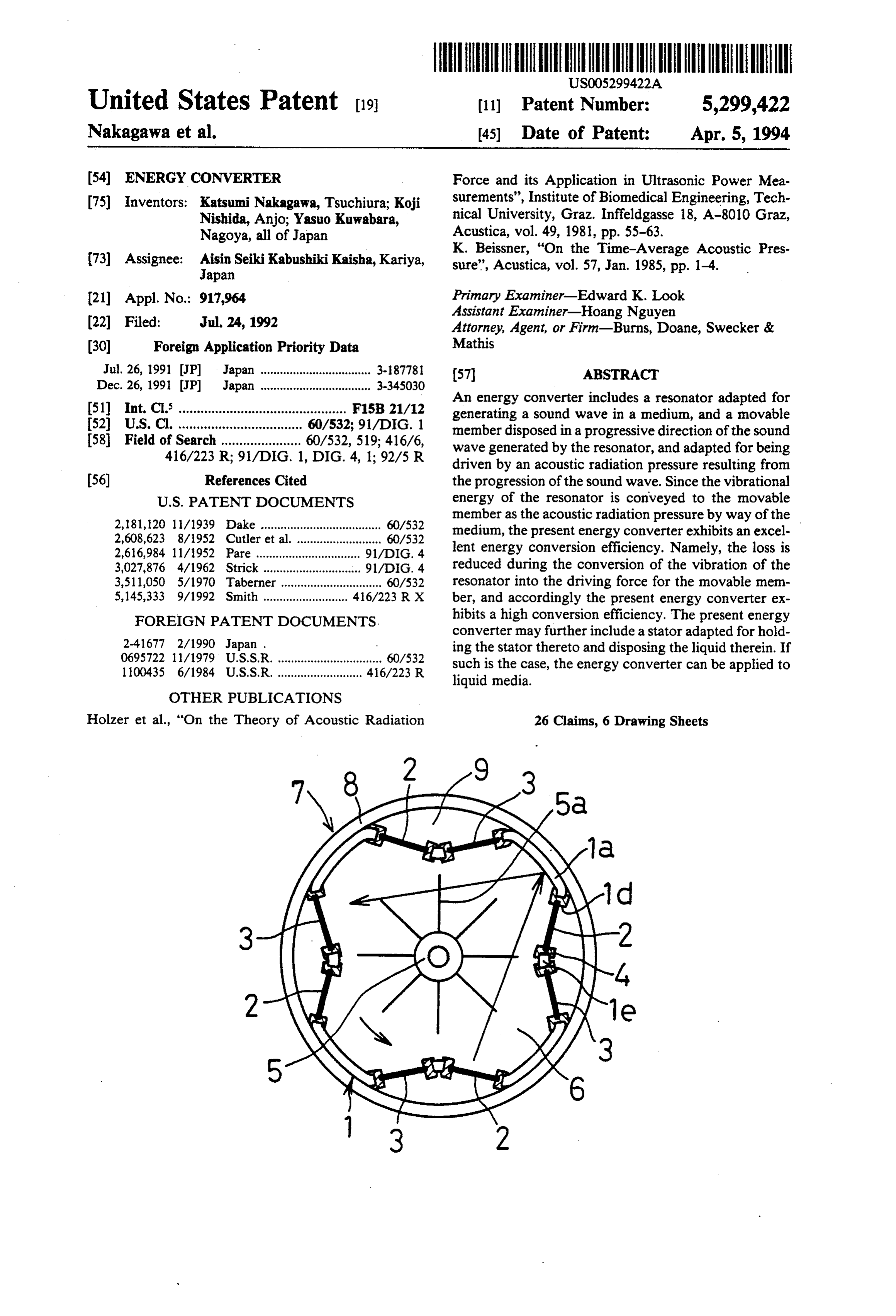
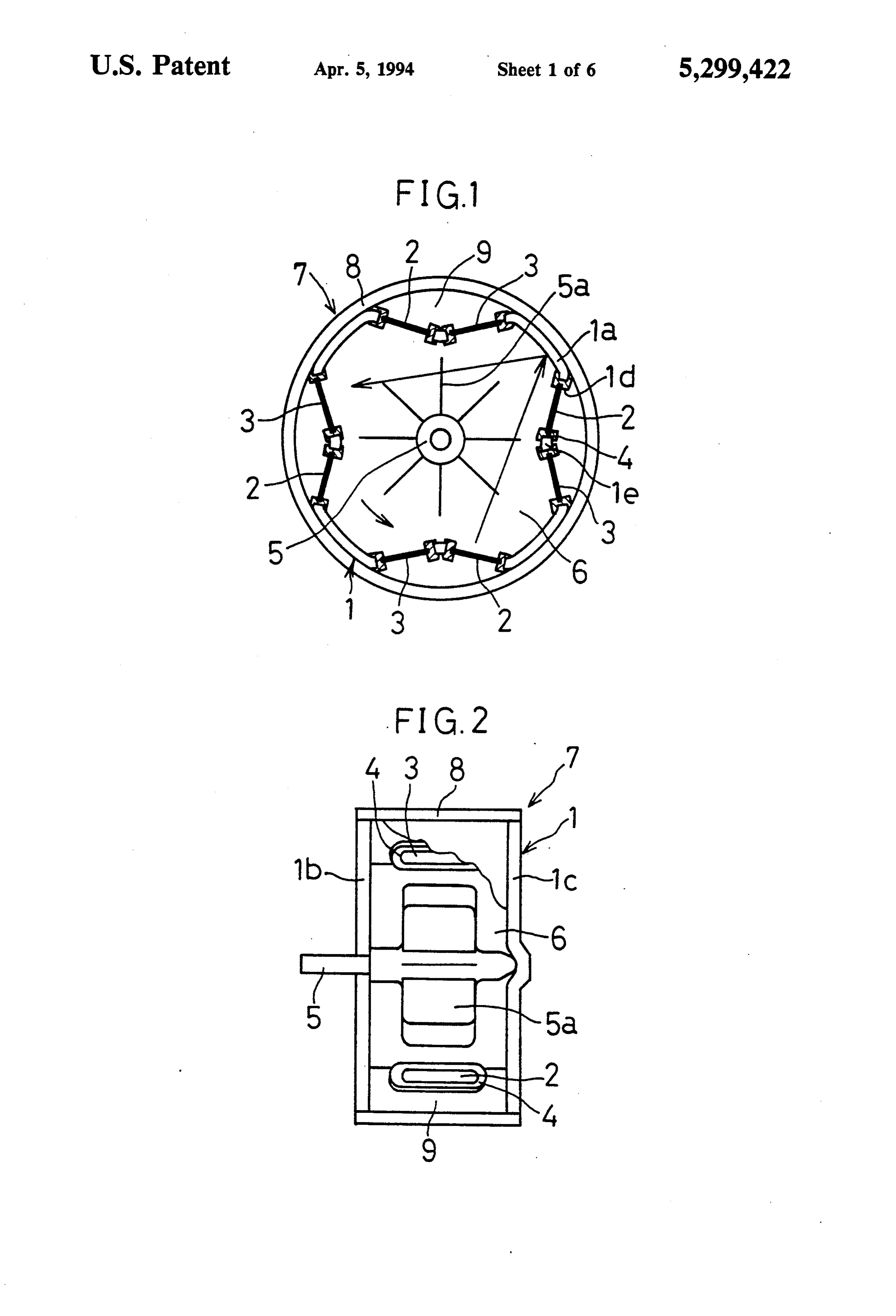
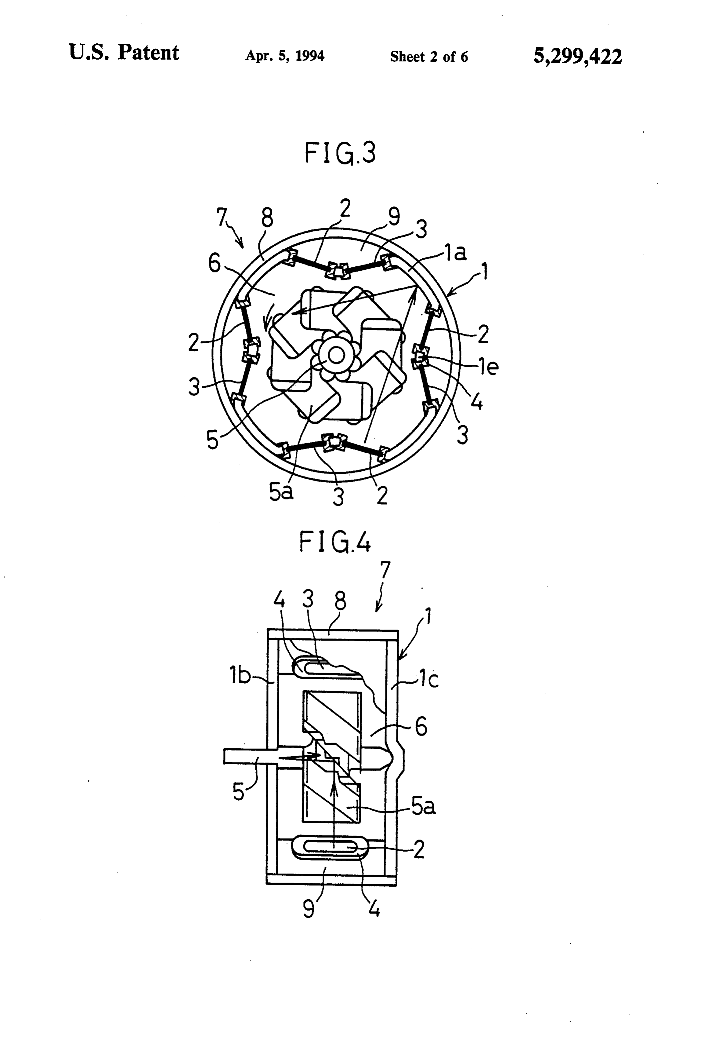
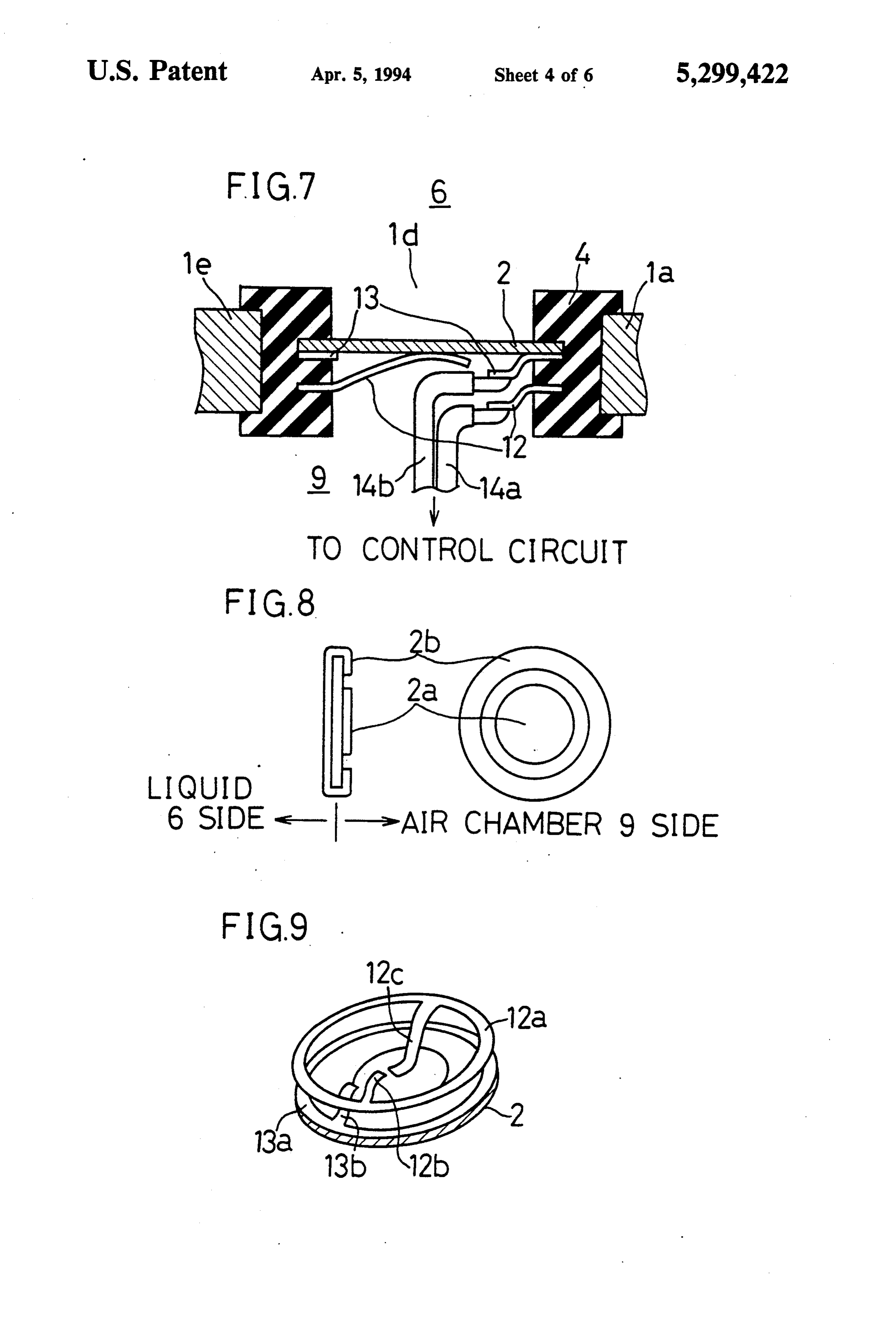
BRIEF DESCRIPTION OF THE DRAWINGS nator 3 which is adapted for rotating the rotor 5 in the A more complete appreciation of the present inven 5 clockwise direction. The resonators 2 and 3 are held to tion and many of its advantages will be readily obtained the side walls 1a and the pillars le by way of rubber as the same becomes better understood by reference to bushings 4 so that they are sealed to each other and so the following detailed description when considered in that they can vibrate. Moreover, in the housing 1, the connection with the accompanying drawings and de rotor 5 is held rotatably to the top and the bottom cov tailed specification, all of which forms a part of the 10 ers 1b and lic. The rotor 5 includes a plurality of blades disclosure: Sa which are made of an ultrasonic wave reflectible FIG. 1 a plan view of an energy converter of a First material and which are disposed radially. These blades Preferred Embodiment according to the present inven 5 are disposed in the progressive directions of the sound tion; waves which are generated by the resonators 2 and 3. In FIG. 2 is a side view of the energy converter illus 15 addition, a liquid is filled in the housing 1. trated in FIG. 2; The energy converter 7 thus constructed can be used FIG. 3 is a plan view of a modified version of the in the same liquid as the liquid 6 which is filled in the energy converter of the First Preferred Embodiment; housing 1. If such is the case, the energy converter 7 is FIG. 4 is a side view of the energy converter illus accommodated in a sealing case 8. With the sealing case trated in FIG. 3; 20 8, there is formed a plurality of air chambers 9 between FIG. 5 is a plan view of an energy converter of a the portions of the sealing case 8 facing the liquid 6 (or Second Preferred Embodiment according to the pres the portions of the sealing case 8 facing the windows 1d) ent invention; and the resonators 2 and 3. Namely, the resonators 2 FIG. 6 is a plan view of a modified version of the and 3 interpose between the liquid 6 and the portions of energy converter of the Second Preferred Embodi 25 the sealing case 8. These air chambers 9 are provided in ment; order to effectively propagate the sound waves, which FIG. 7 is an enlarged cross sectional view of a con are generated by the vibrations of the resonators 2 and struction around a resonator in the energy converter of 3, forward to the blades Sa and the side walls 1a in the the First Preferred Embodiment; liquid 6 filled in the housing 1. Here, the sealing case 8 FIG. 8 is a side view and a plan view of the resonator 30 is required only when the energy converter 7 is used in of the energy converter of the First Preferred Embodi liquid media. However, the sealing case 8 is not needed ment; in particular when the energy converter 7 is used in FIG. 9 is a perspective view of the resonator and atmosphere. If such is the case, the housing 1 requires a electrodes of the energy converter of the First Pre close sealing construction in order to completely en ferred Embodiment; 35 close the liquid 6 therein.
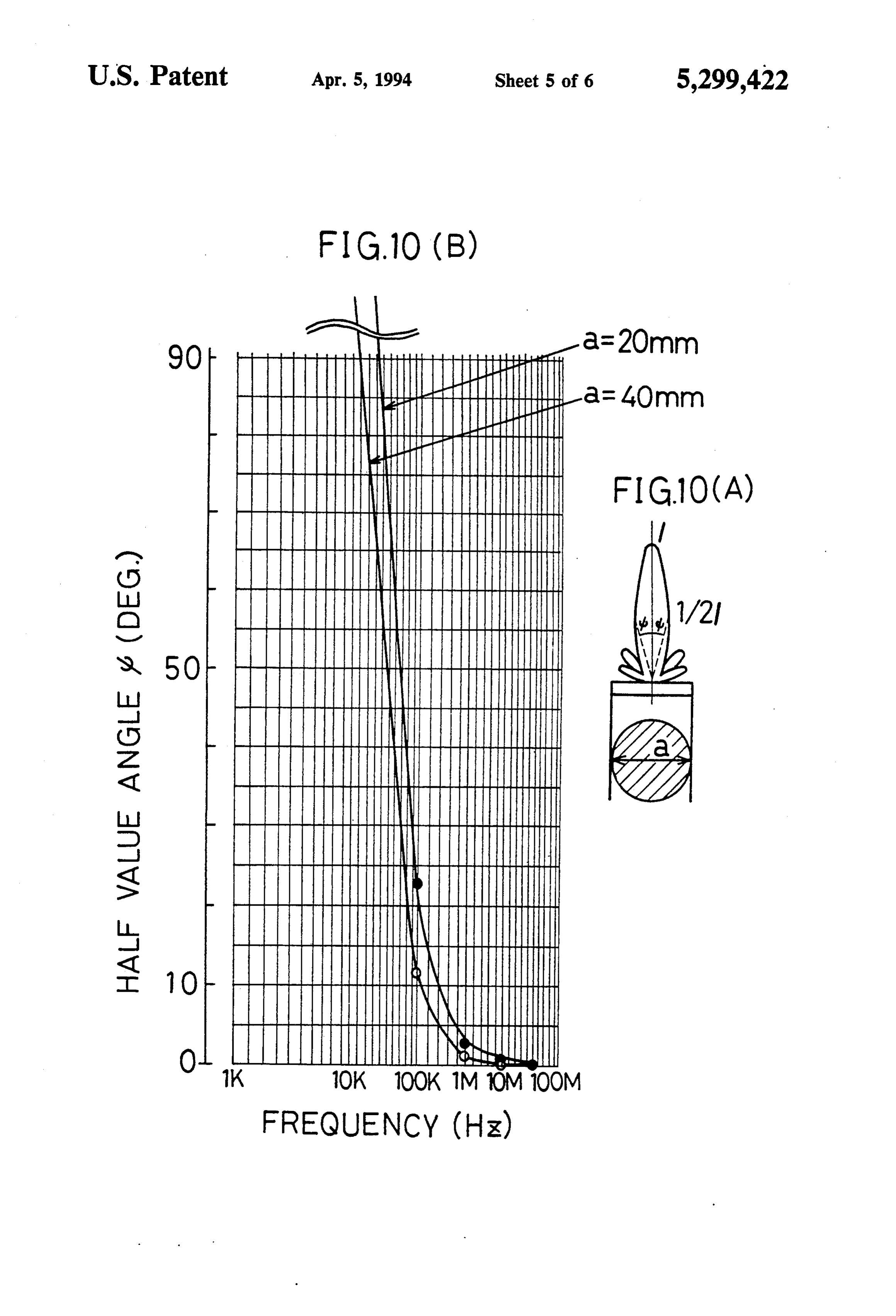
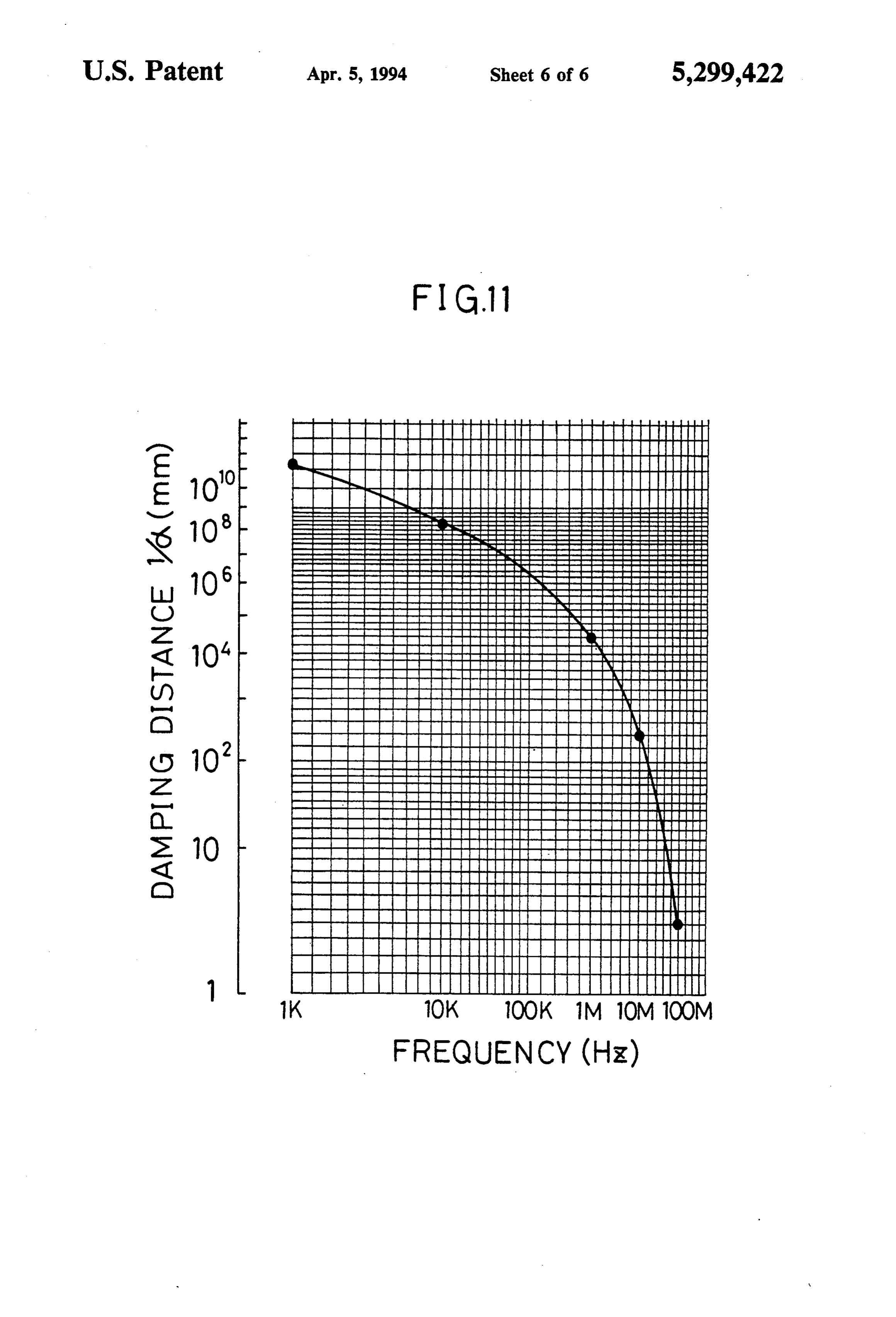
FIG. 10(A) is a schematic illustration of an operation The operation of the energy converter 7 will be here principle of the energy converter according to the pres inafter described. When the resonators 2 are operated to ent invention; generate the sound waves, the liquid 6 generates the FIG. 10(B) is a graphic representation of the opera sound field with the sound waves in the housing 1 ac tion principle of the energy converter according to the 40 cordingly. As a result, the blades Sa of the rotor 5, present invention; and which are disposed in the progressive directions of the FIG. 11 is another graphic representation of the oper sound waves, receive the acoustic radiation pressures ation principle of the energy converter according to the resulting from the progressions of the sound waves in present invention. the sound field generated by the liquid 6. Additionally, 45 the sound waves which pass over or miss the blades 5a
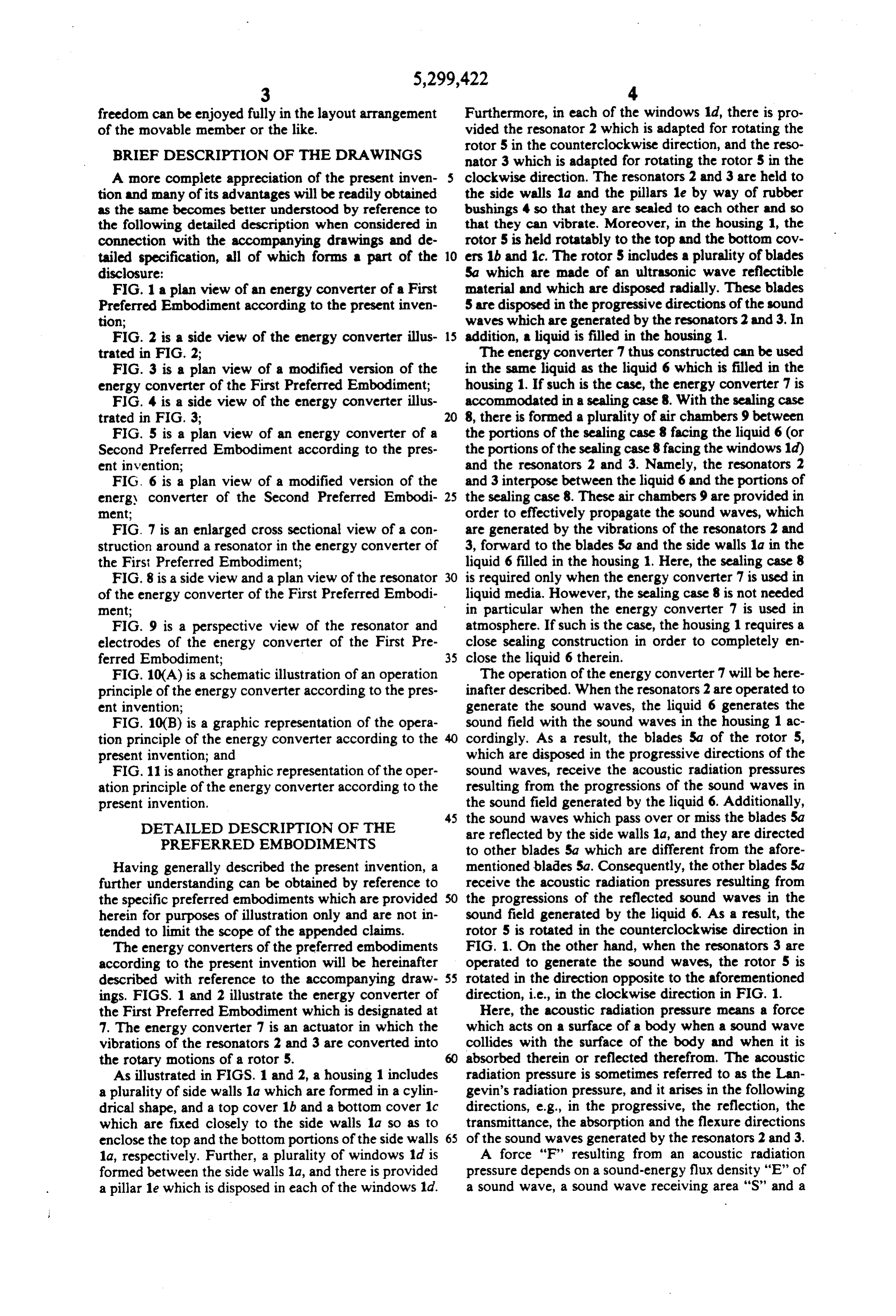
DETAILED DESCRIPTION OF THE are reflected by the side walls 1a, and they are directed PREFERRED EMBODIMENTS to other blades Sa which are different from the afore Having generally described the present invention, a mentioned blades 5a. Consequently, the other blades 5a further understanding can be obtained by reference to receive the acoustic radiation pressures resulting from the specific preferred embodiments which are provided the progressions of the reflected sound waves in the herein for purposes of illustration only and are not in sound field generated by the liquid 6. As a result, the tended to limit the scope of the appended claims. rotor 5 is rotated in the counterclockwise direction in The energy converters of the preferred embodiments FIG. 1. On the other hand, when the resonators 3 are according to the present invention will be hereinafter operated to generate the sound waves, the rotor 5 is described with reference to the accompanying draw 55 rotated in the direction opposite to the aforementioned ings. FIGS. 1 and 2 illustrate the energy converter of direction, i.e., in the clockwise direction in FIG. 1. the First Preferred Embodiment which is designated at Here, the acoustic radiation pressure means a force 7. The energy converter 7 is an actuator in which the which acts on a surface of a body when a sound wave vibrations of the resonators 2 and 3 are converted into collides with the surface of the body and when it is the rotary motions of a rotor 5. 60 absorbed therein or reflected therefrom. The acoustic As illustrated in FIGS. 1 and 2, a housing 1 includes radiation pressure is sometimes referred to as the Lan a plurality of side walls 1a which are formed in a cylin gevin's radiation pressure, and it arises in the following drical shape, and a top cover 1b and a bottom cover 1c directions, e.g., in the progressive, the reflection, the which are fixed closely to the side walls 1a so as to transmittance, the absorption and the flexure directions enclose the top and the bottom portions of the side walls 65 of the sound waves generated by the resonators 2 and 3. 1a, respectively. Further, a plurality of windows 1d is A force "F' resulting from an acoustic radiation formed between the side walls 1a, and there is provided pressure depends on a sound-energy flux density "E" of a pillar le which is disposed in each of the windows 1d. a sound wave, a sound wave receiving area "S" and a
Page 10
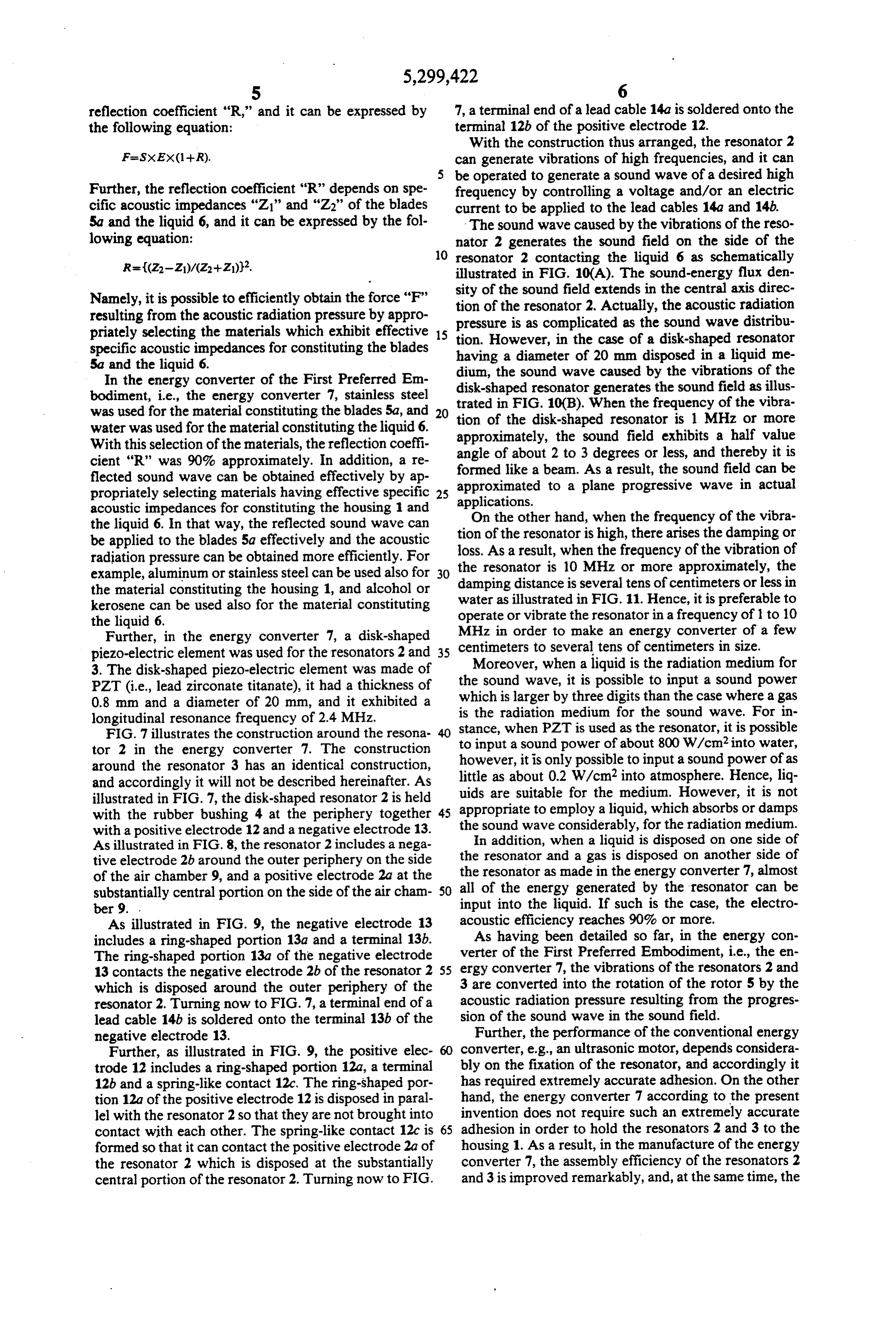
reflection coefficient "R," and it can be expressed by 7, a terminal end of a lead cable 14a is soldered onto the the following equation: terminal 12b of the positive electrode 12. With the construction thus arranged, the resonator 2 can generate vibrations of high frequencies, and it can be operated to generate a sound wave of a desired high
Further, the reflection coefficient “R” depends on spe frequency by controlling a voltage and/or an electric cific acoustic impedances "Z' and "Z2" of the blades current to be applied to the lead cables 14a and 14b. 5a and the liquid 6, and it can be expressed by the fol The sound wave caused by the vibrations of the reso lowing equation: nator 2 generates the sound field on the side of the 10 resonator 2 contacting the liquid 6 as schematically illustrated in FIG. 10(A). The sound-energy flux den
Namely, it is possible to efficiently obtain the force “F” tion of sity the sound field extends in the central axis direc of the resonator 2. Actually, the acoustic radiation resulting from the acoustic radiation pressure by appro pressure is as complicated as the sound wave distribu priately selecting the materials which exhibit effective 15 tion. However, in the case of a disk-shaped resonator specific acoustic impedances for constituting the blades having a diameter of 20 mm disposed in a liquid me 5a and the liquid 6. dium, the sound wave caused by the vibrations of the In the energy converter of the First Preferred Em disk-shaped resonator generates the sound field as illus bodiment, i.e., the energy converter 7, stainless steel was used for the material constituting the blades 5a, and 20 trated in FIG. 10(B). When the frequency of the vibra water was used for the material constituting the liquid 6. tion of the disk-shaped resonator is 1 MHz or more With this selection of the materials, the reflection coeffi angle of about 2the approximately, sound field exhibits a half value cient "R" was 90% approximately. In addition, a re formed like a beam. Asdegreesto 3
or less, and thereby it is result, the sound field can be flected sound wave can be obtained effectively by ap approximated to a plane progressive wave in actual propriately selecting materials having effective specific 25 applications.
acoustic impedances for constituting the housing 1 and the liquid 6. In that way, the reflected sound wave can On the other hand, when the frequency of the vibra be applied to the blades 5a effectively and the acoustic tion of the resonator is high, there arises the damping or radiation pressure can be obtained more efficiently. For loss.the
As a result, when the frequency of the vibration of resonator is 10 MHz or more approximately, the example, aluminum or stainless steel can be used also for damping distance
the material constituting the housing 1, and alcohol or water as illustratedisinseveral tens of centimeters or less in FIG. 11. Hence, it is preferable to kerosene can be used also for the material constituting operate or vibrate the resonator in a frequency of 1 to 10 the liquid 6.
Further, in the energy converter 7, a disk-shaped MHz in order to make an energy converter of a few piezo-electric element was used for the resonators 2 and 35 centimeters to several tens of centimeters in size. 3. The disk-shaped piezo-electric element was made of theMoreover, when a liquid is the radiation medium for sound wave, it is possible to input a sound power
PZT (i.e., lead zirconate titanate), it had a thickness of which is larger by three digits than the case where a gas 0.8 mm and a diameter of 20 mm, and it exhibited a is the radiation medium for the sound wave. For in longitudinal resonance frequency of 2.4 MHz.
FIG. 7 illustrates the construction around the resona 40 stance, when PZT is used as the resonator, it is possible tor 2 in the energy converter 7. The construction to input a sound power of about 800 W/cm2 into water, however, it is only possible to input a sound power of as around the resonator 3 has an identical construction, and accordingly it will not be described hereinafter. As uidslittle as about 0.2 W/cm2 into atmosphere. Hence, liq are suitable for the medium. However, it is not illustrated in FIG. 7, the disk-shaped resonator 2 is held appropriate with the rubber bushing 4 at the periphery together 45 to employ a liquid, which absorbs or damps with a positive electrode 12 and a negative electrode 13. theInsound wave considerably, for the radiation medium. addition, when a liquid is disposed on one side of
As illustrated in FIG. 8, the resonator 2 includes a nega the resonator and a gas is disposed on another side of tive electrode 2b around the outer periphery on the side of the air chamber 9, and a positive electrode 2a at the the resonator as made in the energy converter 7, almost substantially central portion on the side of the air cham 50 all of the energy generated by the resonator can be ber 9. . input into the liquid. If such is the case, the electro As illustrated in FIG. 9, the negative electrode 13 acoustic efficiency reaches 90% or more. includes a ring-shaped portion 13a and a terminal 13b. As having been detailed so far, in the energy con The ring-shaped portion 13a of the negative electrode verter of the First Preferred Embodiment, i.e., the en 13 contacts the negative electrode 2b of the resonator 2 55 ergy converter 7, the vibrations of the resonators 2 and which is disposed around the outer periphery of the 3 are converted into the rotation of the rotor 5 by the resonator 2. Turning now to FIG. 7, a terminal end of a acoustic radiation pressure resulting from the progres lead cable 14b is soldered onto the terminal 13.b of the sion of the sound wave in the sound field. negative electrode 13. Further, the performance of the conventional energy Further, as illustrated in FIG. 9, the positive elec converter, e.g., an ultrasonic motor, depends considera trode 12 includes a ring-shaped portion 12a, a terminal bly on the fixation of the resonator, and accordingly it 12b and a spring-like contact 12c. The ring-shaped por has required extremely accurate adhesion. On the other tion 12a of the positive electrode 12 is disposed in paral hand, the energy converter 7 according to the present lel with the resonator 2 so that they are not brought into invention does not require such an extremely accurate contact with each other. The spring-like contact 12c is 65 adhesion in order to hold the resonators 2 and 3 to the formed so that it can contact the positive electrode 2a of housing 1. As a result, in the manufacture of the energy the resonator 2 which is disposed at the substantially converter 7, the assembly efficiency of the resonators 2 central portion of the resonator 2. Turning now to FIG. and 3 is improved remarkably, and, at the same time, the
Page 11
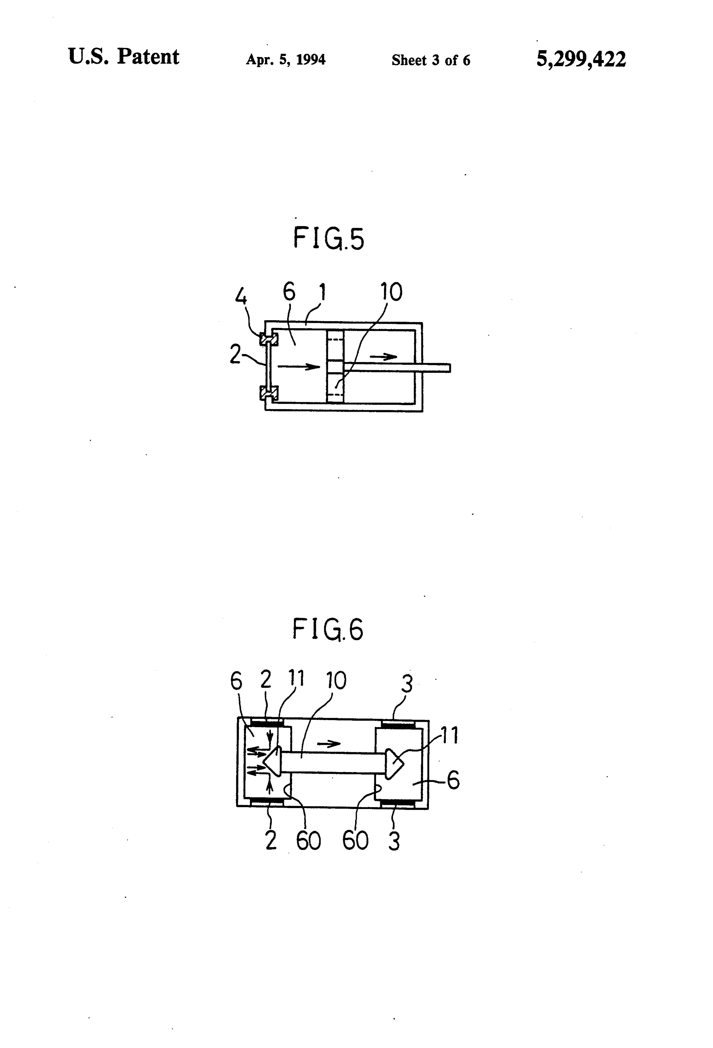
performance stability and the reliability are upgraded 1 and which includes a pair of cones 11, 11 disposed on sharply. the both ends, a pair of resonators 2, 2 which are dis Furthermore, the energy converter 7 can be used in posed in one of the liquid chambers 60, 60, a pair of . liquid media to which the conventional energy con resonators 3, 3 which are disposed in another one of the verter has been hardly applied, and accordingly not 5 liquid chambers 60, 60, and a liquid 6 which is filled in only the application fields of the energy converter 7 are the liquid chambers 60, 60.
widened greatly, but also the cooling efficiency of the With this construction, the piston 10 can be operated energy converter 7 can be expected to improve satisfac reciprocatively by selectively operating either the reso torily. nators 2 or the resonators 3. It goes without saying that Moreover, according to the operation principle de 10 the modified version of the energy converter of the scribed above, the acoustic radiation pressure arises also Second Preferred Embodiment provides the same ad in the following directions: e.g., in the progressive di vantageous effects as those of the energy converter 7 of rections of the sound waves generated by the resonators the First Preferred Embodiment.
2 and 3 after the reflection, in the progressive directions Having now fully described the present invention, it of the sound waves after the transmittance, in the pro s will be apparent to one of ordinary skill in the art that gressive directions of the sound waves after the absorp many changes and modifications can be made thereto tion and in the progressive directions of the sound without departing from the spirit or scope of the present waves after the flexure. As a result, a greater designing invention as set forth herein including the appended freedom can be enjoyed fully in the layout arrangement claims.
of the rotor 5 or the like. 20 What is claimed is:
MODIFIED VERSION OF THE FIRST
1. An energy converter, comprising:
PREFERRED EMBODIMENT
a resonator adapter to operate at a range of frequen cies at which the resonator generates a sound wave
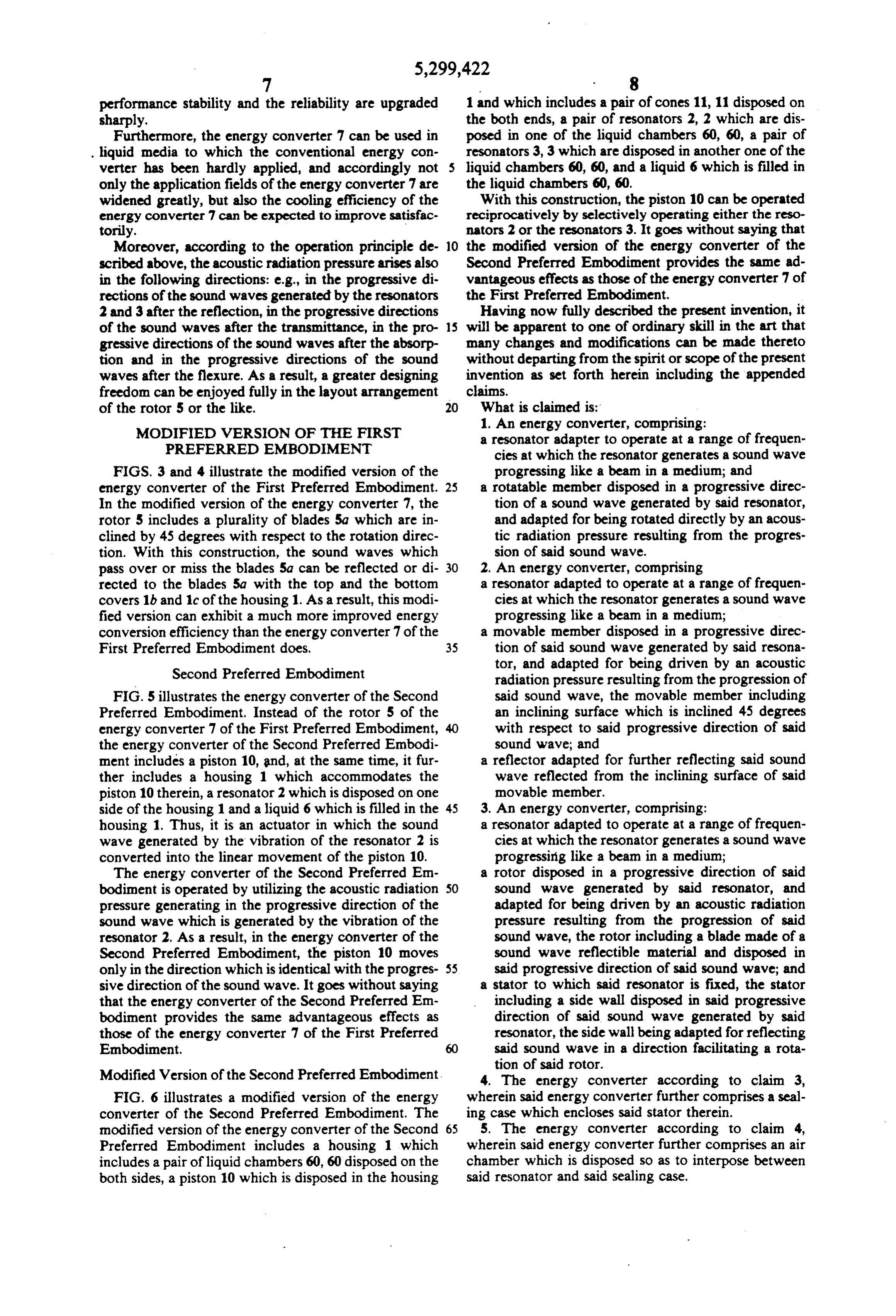
FIGS. 3 and 4 illustrate the modified version of the progressing like a beam in a medium; and energy converter of the First Preferred Embodiment. 25 a rotatable member disposed in a progressive direc In the modified version of the energy converter 7, the tion of a sound wave generated by said resonator, rotor 5 includes a plurality of blades 5a which are in and adapted for being rotated directly by an acous clined by 45 degrees with respect to the rotation direc tic radiation pressure resulting from the progres tion. With this construction, the sound waves which sion of said sound wave.
pass over or miss the blades 5a can be reflected or di 30 2. An energy converter, comprising rected to the blades 5a with the top and the bottom a resonator adapted to operate at a range of frequen covers 1b and 1c of the housing 1. As a result, this modi cies at which the resonator generates a sound wave fied version can exhibit a much more improved energy progressing like a beam in a medium; conversion efficiency than the energy converter 7 of the a movable member disposed in a progressive direc First Preferred Embodiment does, 35 tion of said sound wave generated by said resona Second Preferred Embodiment tor, and adapted for being driven by an acoustic radiation pressure resulting from the progression of
FIG. 5 illustrates the energy converter of the Second said sound wave, the movable member including Preferred Embodiment. Instead of the rotor 5 of the an inclining surface which is inclined 45 degrees energy converter 7 of the First Preferred Embodiment, with respect to said progressive direction of said the energy converter of the Second Preferred Embodi sound wave; and ment includes a piston 10, and, at the same time, it fur a reflector adapted for further reflecting said sound ther includes a housing 1 which accommodates the wave reflected from the inclining surface of said piston 10 therein, a resonator 2 which is disposed on one movable member.
side of the housing 1 and a liquid 6 which is filled in the 45 3. An energy converter, comprising: housing 1. Thus, it is an actuator in which the sound a resonator adapted to operate at a range of frequen wave generated by the vibration of the resonator 2 is cies at which the resonator generates a sound wave converted into the linear movement of the piston 10. progressing like a beam in a medium; The energy converter of the Second Preferred Ern a rotor disposed in a progressive direction of said bodiment is operated by utilizing the acoustic radiation 50 sound wave generated by said resonator, and pressure generating in the progressive direction of the adapted for being driven by an acoustic radiation sound wave which is generated by the vibration of the pressure resulting from the progression of said resonator 2. As a result, in the energy converter of the sound wave, the rotor including a blade made of a Second Preferred Embodiment, the piston 10 moves sound wave reflectible material and disposed in only in the direction which is identical with the progres 55 said progressive direction of said sound wave; and sive direction of the sound wave. It goes without saying a stator to which said resonator is fixed, the stator that the energy converter of the Second Preferred Em including a side wall disposed in said progressive bodiment provides the same advantageous effects as direction of said sound wave generated by said those of the energy converter 7 of the First Preferred resonator, the side wall being adapted for reflecting Embodiment. said sound wave in a direction facilitating a rota tion of said rotor.
Modified Version of the Second Preferred Embodiment. 4. The energy converter according to claim 3, FIG. 6 illustrates a modified version of the energy wherein said energy converter further comprises a seal converter of the Second Preferred Embodiment. The ing case which encloses said stator therein. modified version of the energy converter of the Second 65 5. The energy converter according to claim 4, Preferred Embodiment includes a housing 1 which wherein said energy converter further comprises an air includes a pair of liquid chambers 60, 60 disposed on the chamber which is disposed so as to interpose between both sides, a piston 10 which is disposed in the housing said resonator and said sealing case.
Page 12
6. The energy converter according to claim 3, 16. The energy converter according to claim 14, wherein said rotor includes a plurality of said blades wherein said energy converter further comprises a seal which incline by 45 degrees with respect to said rota ing case which encloses said stator therein. tion of said rotor. 17. The energy converter according to claim 16, 7. The energy converter according to claim 6, wherein said energy converter further comprises an air wherein said stator includes a plurality of said side chamber which is disposed so as to interpose between walls, and said energy converter further comprises a said resonator and said sealing case. plurality of said resonators which is adapted for rotating 18. An energy converter, comprising: said rotor in a clockwise direction and a plurality of said a stator;
resonators which is adapted for rotating said rotor in a 10 a resonator held to said stator, and adapted to operate counterclockwise direction. at a range of frequencies at which the resonator 8. An energy converter, comprising; generates a sound wave progressing like a beam; a resonator adapted to operate at a range of frequen a medium disposed in said stator, and adapted for cies at which the resonator generates a sound wave generating a sound field with said sound wave progressing like a beam in a medium: 15 generated by said resonator; and a rotor disposed in a progressive direction of said a rotor disposed in a progressive direction of said sound wave generated by said resonator, and sound wave generated by said resonator in said adapted for being driven by an acoustic radiation stator, and adapted for being driven by an acoustic pressure resulting from the progression of said radiation pressure resulting from the progression of sound wave, the rotor including means disposed in 20 said sound wave in said sound field generated by said progressive direction of said sound wave and said medium, the rotor including a plurality of adapted for receiving said acoustic radiation pres blades made of a sound wave reflectible material. Sure; 19. The energy converter according to claim 18, said resonator being adapted for rotating said rotor in wherein said blades incline by 45 degrees with respect a clockwise direction and in a counterclockwise 25 to a rotation of said rotor.
direction. 20. The energy converter according to claim 18, 9. The energy converter according to claim 8, wherein said stator includes a plurality of reflectors wherein said means of said rotor is a blade made of a which is adapted for reflecting said sound wave in a sound wave reflectible material. direction facilitating a rotation of the rotor, and said 10. The energy converter according to claim 9, energy converter further comprises a plurality of said wherein said blade inclines by 45 degrees with respect 30 resonators which is adapted for rotating said rotor in a to a rotation of said rotor. clockwise direction and a plurality of said resonators 11. An energy converter, comprising: which is adapted for rotating said rotor in a counter a resonator adapted to operate at a range of frequen clockwise
direction.
energy converter, comprising:
cies at which the resonator generates a sound wave35 a stator;
progressing like a beam in a medium; and a pair of resonators held at least to said stator, dis a movable piston disposed in a progressive direction posed in a predetermined angular relationship, and of said sound wave generated by said resonator, adapted to operate at a range of frequencies at and adapted for being driven by an acoustic radia which the resonators generate a sound wave pro tion pressure resulting from the progression of said gressing like a beam in a medium; and sound wave.
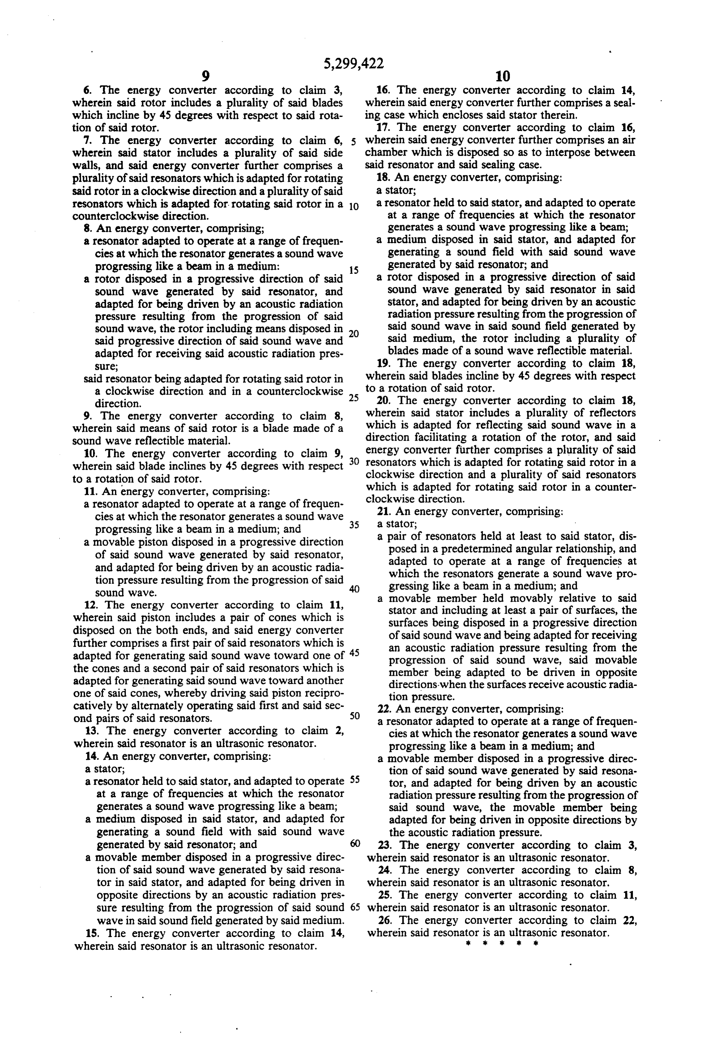
12. The energy converter according to claim 11, a movable member held movably relative to said wherein said piston includes a pair of cones which is stator and including at least a pair of surfaces, the disposed on the both ends, and said energy converter surfaces being disposed in a progressive direction of said sound wave and being adapted for receiving further comprises a first pair of said resonators which is an acoustic radiation pressure resulting from the adapted for generating said sound wave toward one of progression of said sound wave, said movable the cones and a second pair of said resonators which is member being adapted to be driven in opposite adapted for generating said sound wave toward another directions when the surfaces receive acoustic radia one of said cones, whereby driving said piston recipro tion pressure.
catively by alternately operating said first and said sec 22. An energy converter, comprising:
a resonator adapted to operate at a range of frequen 13. The energy converter according to claim 2, cies at which the resonator generates a sound wave wherein said resonator is an ultrasonic resonator. progressing like a beam in a medium; and 14. An energy converter, comprising: a movable member disposed in a progressive direc a stator; tion of said sound wave generated by said resona a resonator held to said stator, and adapted to operate 55 tor, and adapted for being driven by an acoustic at a range of frequencies at which the resonator radiation pressure resulting from the progression of generates a sound wave progressing like a bean; said sound wave, the movable member being a medium disposed in said stator, and adapted for adapted for being driven in opposite directions by generating a sound field with said sound wave the acoustic radiation pressure. generated by said resonator; and 60 23. The energy converter according to claim 3, a movable member disposed in a progressive direc wherein said resonator is an ultrasonic resonator. tion of said sound wave generated by said resona 24. The energy converter according to claim 8, tor in said stator, and adapted for being driven in wherein said resonator is an ultrasonic resonator. opposite directions by an acoustic radiation pres 25. The energy converter according to claim 11, sure resulting from the progression of said sound 65 wherein said resonator is an ultrasonic resonator. wave in said sound field generated by said medium. 26. The energy converter according to claim 22, 15. The energy converter according to claim 14, wherein said resonator s is an ultrasonic resonator.
wherein said resonator is an ultrasonic resonator.
Provenance
- Collection
- Cited prior art
- Original PDF
- patentimages.storage.googleapis.com →
- Filed
- 1992-07-24
- Pages
- 12
- Method
- pdftotext (the PDF's own text layer) + pdftoppm 300dpi page scans
- Source
- Google Patents bibliographic record
- Granted
- 1994-04-05
- Inventors
- Katsumi Nakagawa; Koji Nishida; Yasuo Kuwabara; Aisin Seiki Co Ltd
- Transcribed from
- patentimages.storage.googleapis.com →