patent · US6352068
Method and apparatus for reducing oxides of nitrogen in the exhaust gas of an internal combustion engine
5 March 2002
Page 1 — bibliographic record
(12) United States Patent (10) Patent No.: US 6,352,068 B1 Jacobsen (45) Date of Patent: Mar. 5, 2002
(54) METHOD AND APPARATUS FOR 5,457.958. A 10/1995 Boegner et al. .............. 60/279 REDUCING OXDES OF NITROGEN IN THE 5,636,619 A * 6/1997 Poola et al. ................ 123/585 EXHAUST GAS OF AN INTERNAL 5,640,845 A * 6/1997 Ng et al. ...................... 60/274 COMBUSTION ENGINE 5,649.517 A 7/1997 Poola et al. - - - - - - - - - - - - - - - - 123/585 5,910,097 A 6/1999 Boegner et al. .............. 60/278 5,912,426. A 6/1999 Smolarek et al. ............. 96/115 (75) Inventor: Arthur J. Jacobsen, Dublin, OH (US) 5.960,777. A 10/1999 Nemser et al. ............. 123/585 O O 6,055.808 A * 5/2000 Poola et al. .................. 60/274 (73) Assignee: Honda Giken Kogyo Kabushiki 6,059.858 A 5/2000 Lin et al. ....................... 95/96 Kaisha, Tokyo (JP) 6,067,973 A * 5/2000 Chanda et al. .............. 123/585
(*) Notice: Subject to any disclaimer, the term of this patent is extended or adjusted under 35 * cited by examiner
U.S.C. 154(b) by 0 days. Primary Examiner Willis R. Wolfe
Assistant Examiner Hai Huynh (21) Appl. No.: 09/472,554 (74) Attorney, Agent, or Firm-Rankin, Hill, Porter & (22) Filed: Dec. 27, 1999 Clark LLP 7 (57) ABSTRACT (51) Int. Cl.' ................................................. FO2B 23/00 (52) U.S. Cl. ....................................................... 123/585 A method and apparatus for reducing oxides of nitrogen in (58) Field of Search ................................. 123/585,587, the exhaust of an internal combustion engine. The apparatus 123/568.15, 559.1, 559.2, 698, 699, 26, includes a pressurizing unit for providing compressed air to 563 a pressure Swing adsorption unit. The pressure Swing adsorption removes nitrogen from the air to produce (56) References Cited nitrogen-reduced air, which is then Supplied to the engine. The pressurizing unit may be a compressor, a turbocharger,
4,203,958 A 5/1980 Snarski ....................... 423/351 recirculation and fuel injection with air assist. 4,744,803 A 5/1988 Knaebel ........................ 95/98 4,927,434 A 5/1990 Cordes et al. ................. 95/15 27 Claims, 6 Drawing Sheets
UIL
Page 2
Drawing sheet — no readable text.
Page 3
Drawing sheet — no readable text.
Page 4
Drawing sheet — no readable text.
Page 5
Drawing sheet — no readable text.
Page 6
Drawing sheet — no readable text.
Page 7
Drawing sheet — no readable text.
Page 8
METHOD AND APPARATUS FOR from the production mode of the adsorbent bed is supplied REDUCING OXDES OF NITROGEN IN THE to the air intake System of the engine. EXHAUST GAS OF AN INTERNAL Also provided in accordance with the present invention is COMBUSTION ENGINE an air Supply System for an internal combustion engine. The air Supply System includes a preSSurizing unit and a pressure
BACKGROUND OF THE INVENTION Swing adsorption unit, as described above. The air Supply This invention relates to internal combustion engines in System further includes an air filter through which air may general and, more particularly, to methods and apparatus for be directed to the pressurizing unit, and an air dryer con reducing oxides of nitrogen in the exhaust of internal nected between the air filter and the pressurizing unit. The combustion engines. air dryer contains a desiccant for removing water from the filtered air.
The exhaust gas from an internal combustion engine Also provided in accordance with the present invention is includes a number of undesirable compounds, Such as car bon monoxide, hydrocarbons, and oxides of nitrogen (NO), combustionofengine.
a method reducing NO in the exhaust of an internal namely nitrogen dioxide (NO) and nitric oxide (NO). NO. 15 Viding an adsorbent The method includes the Steps of pro bed and pressurizing air. The pressur is formed at the high temperatures encountered in the ized air is passed through the adsorbent bed, thereby raising combustion flame and increase in formation as the combus tion temperature increases. Exhausting NO into the air has bed the pressure of the adsorbent bed and causing the adsorbent detrimental effects on the environment. NO can photoreact reduced to adsorb nitrogen from the air to produce nitrogen and create air pollution and/or chemically react and contrib air intakeair.System
The nitrogen-reduced air is then directed into an of the engine. In another Step, the pressure ute to acid rain. Accordingly, various Systems have been in the adsorbent developed to reduce NO in the exhaust of internal com from the adsorbent bed. bed is reduced Such that nitrogen desorbs bustion engines. The nitrogen is then directed to the outside atmosphere.
One Such system is an exhaust-gas recirculation (EGR)
System, wherein a portion of the exhaust gas is introduced 25 anAlso provided in accordance with the present invention is into an air intake of the engine, thereby lowering the total having an System engine including an internal combustion engine oxygen concentration of the intake charge. Lowering the pressed airairareintake System. Means for producing com oxygen concentration decreases the peak combustion producing nitrogen-reduced Alsoprovided. provided are means for air and nitrogen gas from the temperature, which, in turn, reduces the formation of NO. compressed air using changes in preSSure. The nitrogen Although an EGR system reduces NO formation, an reduced air is provided to the air intake System of the engine. EGR System increases hydrocarbon emissions. Moreover, only So much air can be replaced with the recycled exhaust BRIEF DESCRIPTION OF THE DRAWINGS gas before combustion becomes unstable.
Another System that is used to reduce NO in exhaust gas The features, aspects, and advantages of the present is catalytic reduction, wherein NO is removed from the 35 invention will become better understood with regard to the exhaust gas by reaction with in-situ reductants, Such as following description, appended claims, and accompanying carbon monoxide or hydrocarbons (HC), when passed over drawings where:
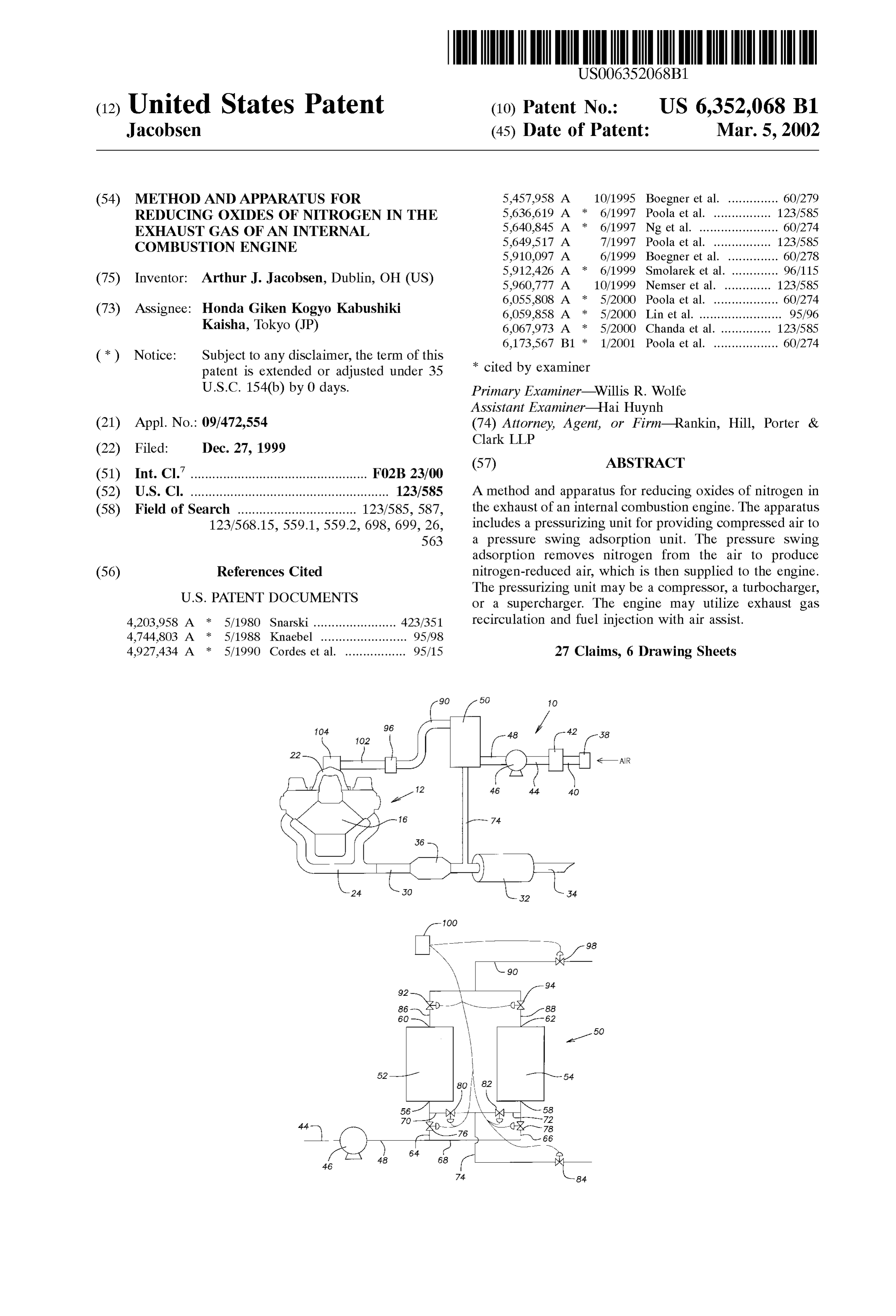
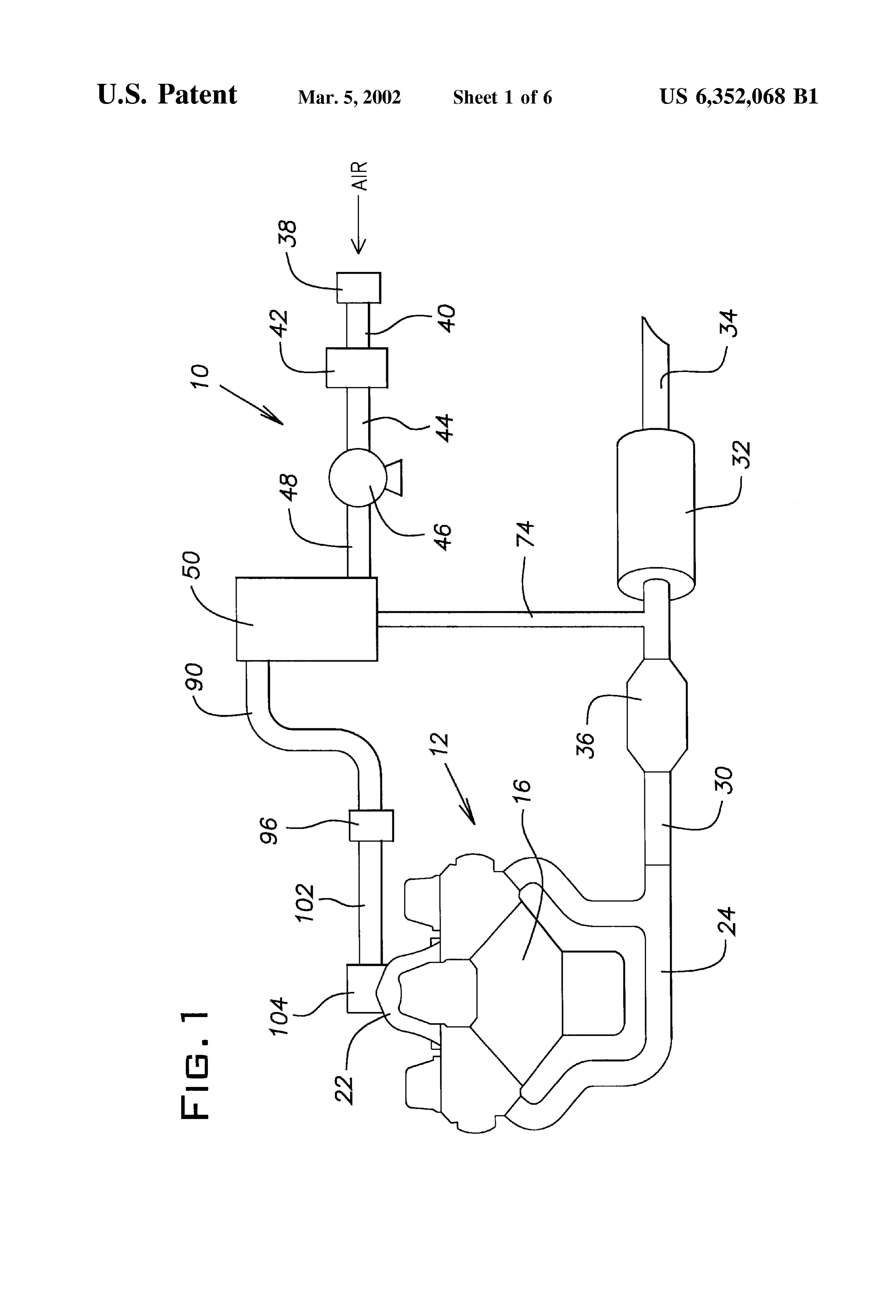
a catalyst, typically containing rhodium. Such catalytic FIG. 1 shows a Schematic diagram of a first engine System reduction, however, cannot cost-effectively reduce NO to 40 having a pressure Swing adsorption unit; meet more Stringent future government regulations. FIG. 2 shows a Schematic diagram of the pressure Swing Based on the foregoing, there is a need in the art for an adsorption unit;
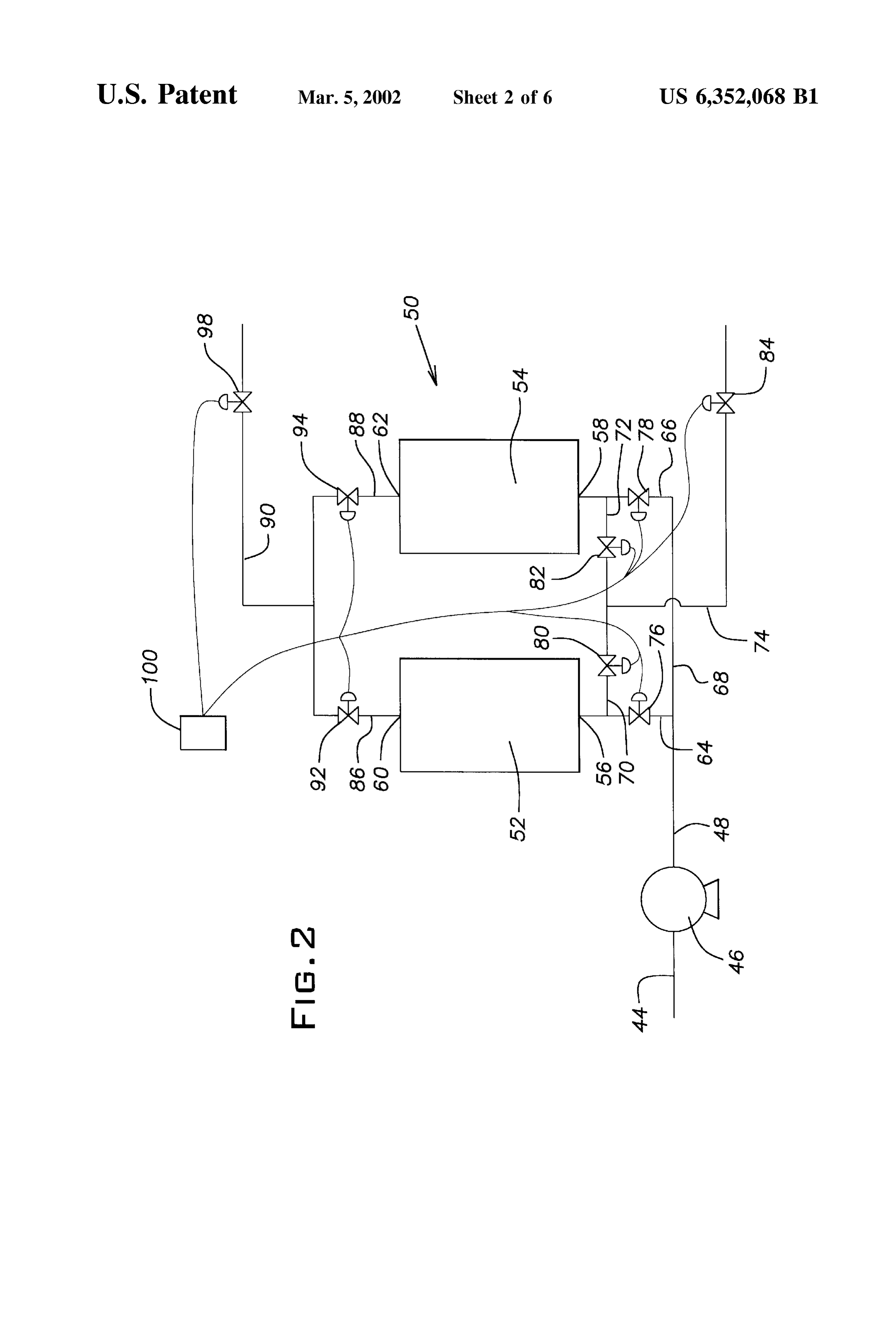
improved method and apparatus for reducing oxides of FIG. 3 shows a portion of a Second engine System having nitrogen in the exhaust of an internal combustion engine. the pressure Swing adsorption unit;
The present invention is directed to Such a method and 45 FIG. 4 shows a schematic diagram of a portion of a third apparatuS. engine System having the pressure Swing adsorption unit; SUMMARY OF THE INVENTION FIG. 5 shows a Schematic diagram of a fourth engine System having the pressure Swing adsorption unit; and
It therefore would be desirable, and is an advantage of the FIG. 6 shows a Schematic diagram of a fifth engine System present invention, to provide an engine System having an 50 having the pressure Swing adsorption unit. internal combustion engine with a plurality of cylinders.
Each of the cylinderS has an intake port and an exhaust port. DETAILED DESCRIPTION OF THE An air intake System is provided through which air is PREFERRED EMBODIMENTS directed to the cylinders of the engine, and an exhaust
System is provided for directing exhaust gas generated by 55 It should be noted that in the detailed description which combustion in the cylinders to the outside atmosphere. A follows, identical components have the same reference preSSurizing unit and a pressure Swing adsorption unit are numerals, regardless of whether they are shown in different also provided. The pressure Swing adsorption unit has an embodiments of the present invention. It should also be inlet connected to the pressurizing unit to receive com noted that in order to clearly and concisely disclose the pressed air therefrom, and an outlet connected to the air 60 present invention, the drawings may not necessarily be to intake System of the engine. The preSSure Swing adsorption Scale and certain features of the invention may be shown in unit also includes an adsorbent bed cyclable between a Somewhat Schematic form.
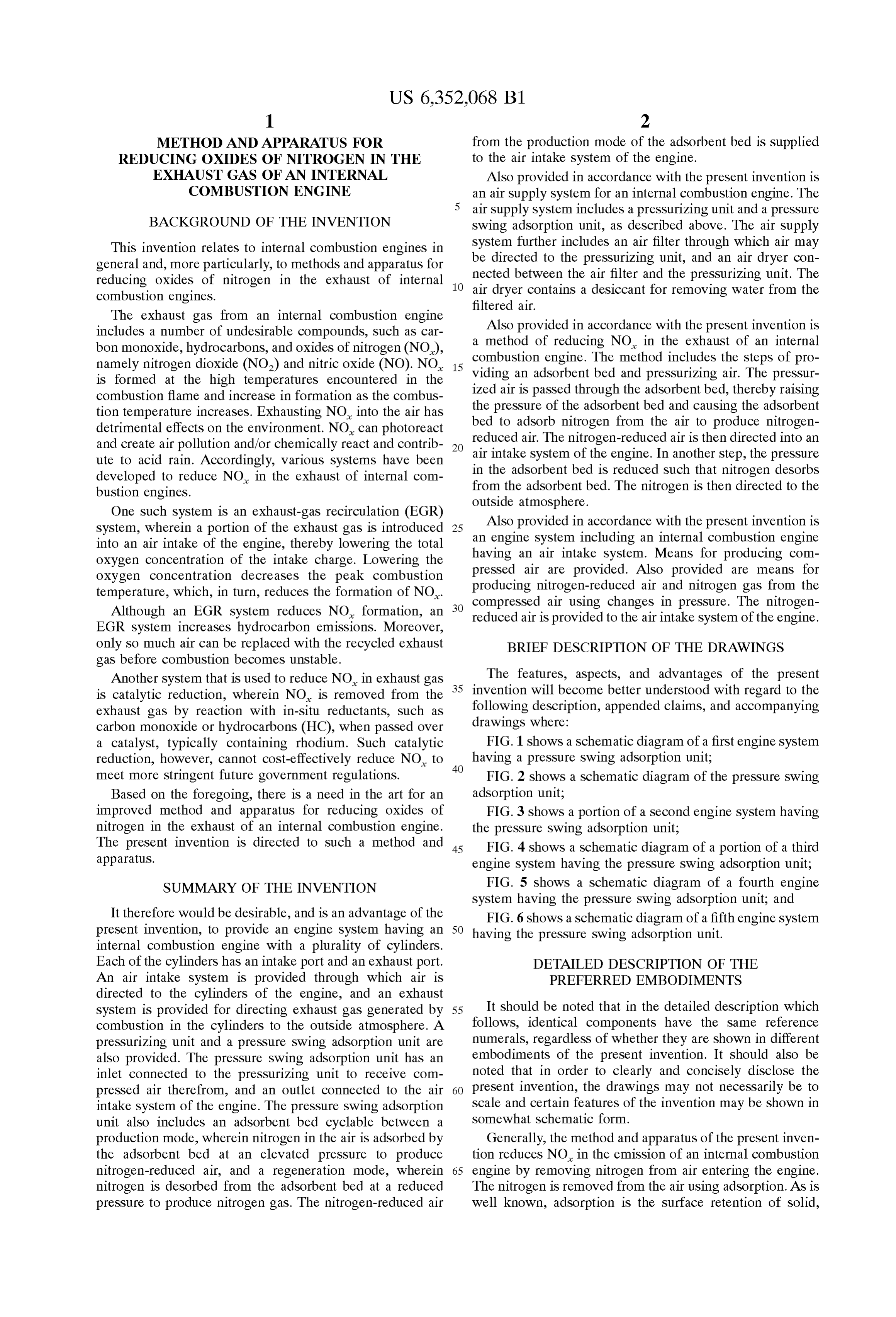
production mode, wherein nitrogen in the air is adsorbed by Generally, the method and apparatus of the present inven the adsorbent bed at an elevated pressure to produce tion reduces NO in the emission of an internal combustion nitrogen-reduced air, and a regeneration mode, wherein 65 engine by removing nitrogen from air entering the engine. nitrogen is desorbed from the adsorbent bed at a reduced The nitrogen is removed from the air using adsorption. AS is preSSure to produce nitrogen gas. The nitrogen-reduced air well known, adsorption is the Surface retention of Solid,
Page 9
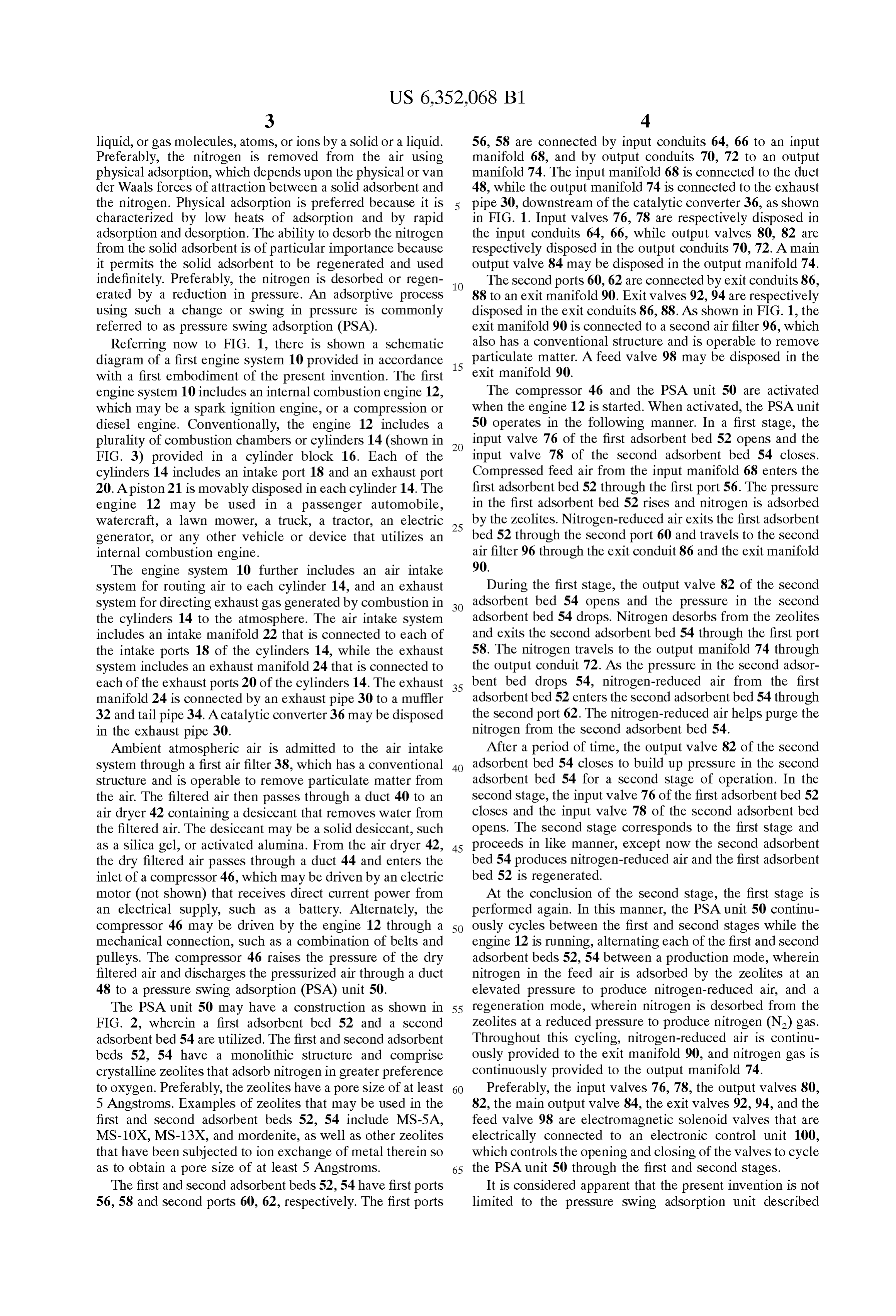
liquid, or gas molecules, atoms, or ions by a Solid or a liquid. 56, 58 are connected by input conduits 64, 66 to an input Preferably, the nitrogen is removed from the air using manifold 68, and by output conduits 70, 72 to an output physical adsorption, which depends upon the physical or van manifold 74. The input manifold 68 is connected to the duct der Waals forces of attraction between a Solid adsorbent and 48, while the output manifold 74 is connected to the exhaust the nitrogen. Physical adsorption is preferred because it is pipe 30, downstream of the catalytic converter 36, as shown characterized by low heats of adsorption and by rapid in FIG. 1. Input valves 76, 78 are respectively disposed in adsorption and desorption. The ability to desorb the nitrogen the input conduits 64, 66, while output valves 80, 82 are from the Solid adsorbent is of particular importance because respectively disposed in the output conduits 70, 72. A main it permits the Solid adsorbent to be regenerated and used output valve 84 may be disposed in the output manifold 74. indefinitely. Preferably, the nitrogen is desorbed or regen The second ports 60, 62 are connected by exit conduits 86, erated by a reduction in pressure. An adsorptive proceSS 88 to an exit manifold 90. Exit valves 92,94 are respectively using Such a change or Swing in preSSure is commonly disposed in the exit conduits 86,88. As shown in FIG. 1, the referred to as pressure Swing adsorption (PSA). exit manifold 90 is connected to a second air filter 96, which Referring now to FIG. 1, there is shown a schematic also has a conventional Structure and is operable to remove diagram of a first engine System 10 provided in accordance 15 particulate matter. A feed valve 98 may be disposed in the with a first embodiment of the present invention. The first exit manifold 90.
engine System 10 includes an internal combustion engine 12, The compressor 46 and the PSA unit 50 are activated which may be a Spark ignition engine, or a compression or when the engine 12 is started. When activated, the PSA unit diesel engine. Conventionally, the engine 12 includes a 50 operates in the following manner. In a first Stage, the plurality of combustion chambers or cylinders 14 (shown in input valve 76 of the first adsorbent bed 52 opens and the FIG. 3) provided in a cylinder block 16. Each of the input valve 78 of the second adsorbent bed 54 closes. cylinders 14 includes an intake port 18 and an exhaust port Compressed feed air from the input manifold 68 enters the 20. A piston 21 is movably disposed in each cylinder 14. The first adsorbent bed 52 through the first port 56. The pressure engine 12 may be used in a passenger automobile, in the first adsorbent bed 52 rises and nitrogen is adsorbed watercraft, a lawn mower, a truck, a tractor, an electric 25 by the Zeolites. Nitrogen-reduced air exits the first adsorbent generator, or any other vehicle or device that utilizes an bed 52 through the second port 60 and travels to the second internal combustion engine. air filter 96 through the exit conduit 86 and the exit manifold The engine system 10 further includes an air intake 90.
System for routing air to each cylinder 14, and an exhaust During the first stage, the output valve 82 of the second System for directing exhaust gas generated by combustion in adsorbent bed 54 opens and the pressure in the second the cylinderS 14 to the atmosphere. The air intake System adsorbent bed 54 drops. Nitrogen desorbs from the Zeolites includes an intake manifold 22 that is connected to each of and exits the second adsorbent bed 54 through the first port the intake ports 18 of the cylinders 14, while the exhaust 58. The nitrogen travels to the output manifold 74 through System includes an exhaust manifold 24 that is connected to the output conduit 72. AS the pressure in the Second adsor each of the exhaust ports 20 of the cylinders 14. The exhaust 35 bent bed drops 54, nitrogen-reduced air from the first manifold 24 is connected by an exhaust pipe 30 to a muffler adsorbentbed 52 enters the second adsorbentbed 54 through 32 and tail pipe 34. A catalytic converter 36 may be disposed the Second port 62. The nitrogen-reduced air helps purge the in the exhaust pipe 30. nitrogen from the second adsorbent bed 54. Ambient atmospheric air is admitted to the air intake After a period of time, the output valve 82 of the second system through a first air filter 38, which has a conventional 40 adsorbent bed 54 closes to build up pressure in the second Structure and is operable to remove particulate matter from adsorbent bed 54 for a second stage of operation. In the the air. The filtered air then passes through a duct 40 to an second stage, the input valve 76 of the first adsorbent bed 52 air dryer 42 containing a desiccant that removes water from closes and the input valve 78 of the second adsorbent bed the filtered air. The desiccant may be a Solid desiccant, Such opens. The Second Stage corresponds to the first stage and as a Silica gel, or activated alumina. From the air dryer 42, 45 proceeds in like manner, except now the Second adsorbent the dry filtered air passes through a duct 44 and enters the bed 54 produces nitrogen-reduced air and the first adsorbent inlet of a compressor 46, which may be driven by an electric bed 52 is regenerated.
motor (not shown) that receives direct current power from At the conclusion of the Second Stage, the first Stage is an electrical Supply, Such as a battery. Alternately, the performed again. In this manner, the PSA unit 50 continu compressor 46 may be driven by the engine 12 through a 50 ously cycles between the first and Second Stages while the mechanical connection, Such as a combination of belts and engine 12 is running, alternating each of the first and Second pulleys. The compreSSor 46 raises the pressure of the dry adsorbent beds 52, 54 between a production mode, wherein filtered air and discharges the pressurized air through a duct nitrogen in the feed air is adsorbed by the Zeolites at an 48 to a pressure Swing adsorption (PSA) unit 50. elevated preSSure to produce nitrogen-reduced air, and a The PSA unit 50 may have a construction as shown in 55 regeneration mode, wherein nitrogen is desorbed from the FIG. 2, wherein a first adsorbent bed 52 and a second Zeolites at a reduced pressure to produce nitrogen (N) gas. adsorbentbed 54 are utilized. The first and second adsorbent Throughout this cycling, nitrogen-reduced air is continu beds 52, 54 have a monolithic structure and comprise ously provided to the exit manifold 90, and nitrogen gas is crystalline Zeolites that adsorb nitrogen in greater preference continuously provided to the output manifold 74. to oxygen. Preferably, the Zeolites have a pore size of at least 60 Preferably, the input valves 76, 78, the output valves 80, 5 Angstroms. Examples of Zeolites that may be used in the 82, the main output valve 84, the exit valves 92,94, and the first and second adsorbent beds 52, 54 include MS-5A, feed valve 98 are electromagnetic Solenoid valves that are MS-10X, MS-13X, and mordenite, as well as other Zeolites electrically connected to an electronic control unit 100, that have been Subjected to ion exchange of metal therein So which controls the opening and closing of the valves to cycle as to obtain a pore size of at least 5 Angstroms. 65 the PSA unit 50 through the first and second stages. The first and second adsorbent beds 52, 54 have first ports It is considered apparent that the present invention is not 56, 58 and second ports 60, 62, respectively. The first ports limited to the preSSure Swing adsorption unit described
Page 10
S 6 above and shown in FIG. 2. Rather, other pressure Swing 114, the nitrogen-reduced air is ejected from the air chamber units may be employed with equal functionality and without 120 through the air assist ejection ports and toward a fueljet departing from the Scope and Spirit of the present invention issuing from the fuel ejection port. The fuel particles in the as embodied in the claims appended hereto. For example, a fuel jet are finely atomized by collision with the nitrogen preSSure Swing adsorption unit having four adsorbent: beds depleted air, thereby providing for efficient combustion in may be used for the PSA unit 50. In such a pressure Swing the cylinder 14.
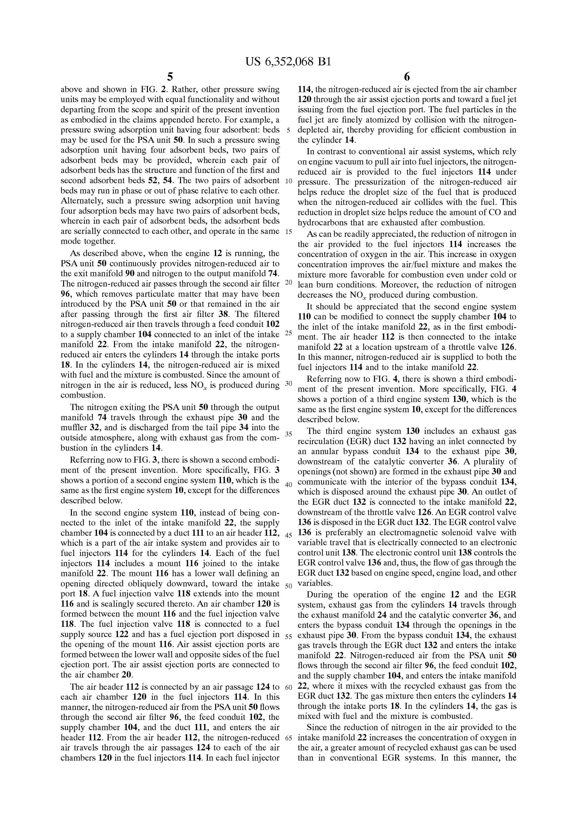
adsorption unit having four adsorbent beds, two pairs of In contrast to conventional air assist Systems, which rely adsorbent beds may be provided, wherein each pair of on engine Vacuum to pull air into fuel injectors, the nitrogen adsorbent beds has the structure and function of the first and reduced air is provided to the fuel injectors 114 under second adsorbent beds 52, 54. The two pairs of adsorbent preSSure. The pressurization of the nitrogen-reduced air beds may run in phase or out of phase relative to each other. helps reduce the droplet size of the fuel that is produced Alternately, Such a pressure Swing adsorption unit having when the nitrogen-reduced air collides with the fuel. This four adsorption beds may have two pairs of adsorbent beds, reduction in droplet Size helps reduce the amount of CO and wherein in each pair of adsorbent beds, the adsorbent beds hydrocarbons that are exhausted after combustion. are Serially connected to each other, and operate in the same 15 AS can be readily appreciated, the reduction of nitrogen in mode together. the air provided to the fuel injectors 114 increases the AS described above, when the engine 12 is running, the concentration of oxygen in the air. This increase in oxygen PSA unit 50 continuously provides nitrogen-reduced air to concentration improves the air/fuel mixture and makes the the exit manifold 90 and nitrogen to the output manifold 74. mixture more favorable for combustion even under cold or The nitrogen-reduced air passes through the Second air filter lean burn conditions. Moreover, the reduction of nitrogen 96, which removes particulate matter that may have been decreases the NO produced during combustion. introduced by the PSA unit 50 or that remained in the air It should be appreciated that the Second engine System after passing through the first air filter 38. The filtered 110 can be modified to connect the Supply chamber 104 to nitrogen-reduced air then travels through a feed conduit 102 the inlet of the intake manifold 22, as in the first embodi to a supply chamber 104 connected to an inlet of the intake 25 ment. The air header 112 is then connected to the intake manifold 22. From the intake manifold 22, the nitrogen manifold 22 at a location upstream of a throttle valve 126. reduced air enters the cylinderS 14 through the intake ports In this manner, nitrogen-reduced air is Supplied to both the 18. In the cylinders 14, the nitrogen-reduced air is mixed fuel injectors 114 and to the intake manifold 22. with fuel and the mixture is combusted. Since the amount of nitrogen in the air is reduced, leSS NO is produced during ment Referring now to FIG. 4, there is shown a third embodi combustion.
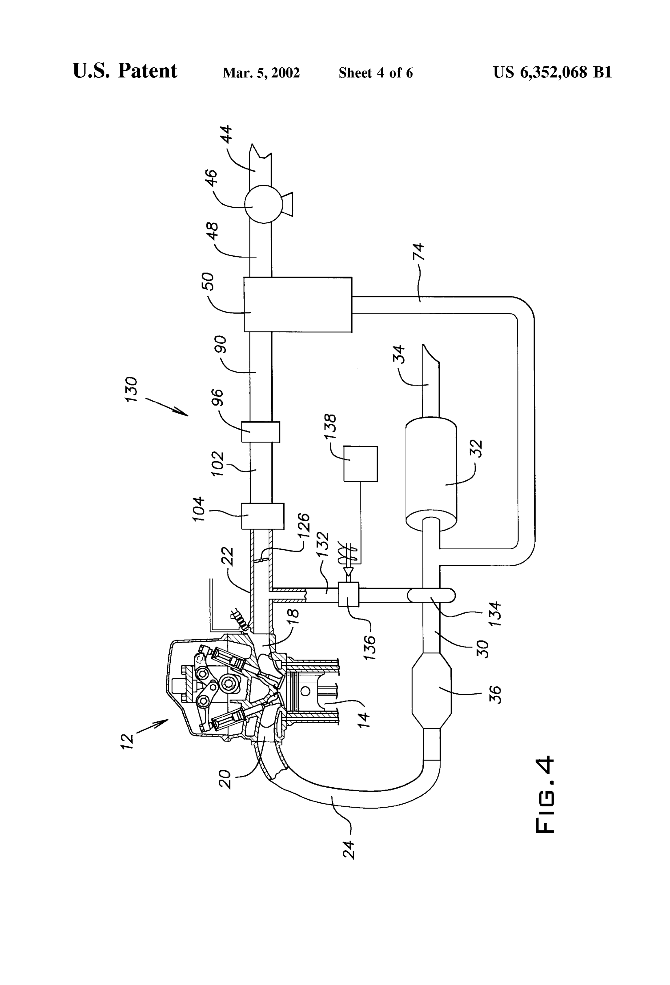
of the present invention. More specifically, FIG. 4 shows a portion of a third engine system 130, which is the
The nitrogen exiting the PSA unit 50 through the output Same as the first engine System 10, except for the differences manifold 74 travels through the exhaust pipe 30 and the described below.
muffler 32, and is discharged from the tail pipe 34 into the The third engine System 130 includes an exhaust gas outside atmosphere, along with exhaust gas from the com 35 recirculation (EGR) duct 132 having an inlet connected by bustion in the cylinders 14. an annular bypass conduit 134 to the exhaust pipe 30, Referring now to FIG. 3, there is shown a second embodi downstream of the catalytic converter 36. A plurality of ment of the present invention. More specifically, FIG. 3 openings (not shown) are formed in the exhaust pipe 30 and shows a portion of a Second engine System 110, which is the 40 communicate with the interior of the bypass conduit 134, Same as the first engine System 10, except for the differences which is disposed around the exhaust pipe 30. An outlet of described below. the EGR duct 132 is connected to the intake manifold 22, In the Second engine System 110, instead of being con downstream of the throttle valve 126. An EGR control valve nected to the inlet of the intake manifold 22, the Supply 136 is disposed in the EGR duct 132. The EGR control valve chamber 104 is connected by a duct 111 to an air header 112, 45 136 is preferably an electromagnetic Solenoid valve with which is a part of the air intake System and provides air to variable travel that is electrically connected to an electronic fuel injectors 114 for the cylinders 14. Each of the fuel control unit 138. The electronic control unit 138 controls the injectors 114 includes a mount 116 joined to the intake EGR control valve 136 and, thus, the flow of gas through the manifold 22. The mount 116 has a lower wall defining an EGR duct 132 based on engine Speed, engine load, and other opening directed obliquely downward, toward the intake 50 variables.
port 18. A fuel injection valve 118 extends into the mount During the operation of the engine 12 and the EGR 116 and is sealingly secured thereto. An air chamber 120 is System, exhaust gas from the cylinderS 14 travels through formed between the mount 116 and the fuel injection valve the exhaust manifold 24 and the catalytic converter 36, and 118. The fuel injection valve 118 is connected to a fuel enters the bypass conduit 134 through the openings in the Supply Source 122 and has a fuel ejection port disposed in 55 exhaust pipe 30. From the bypass conduit 134, the exhaust the opening of the mount 116. Air assist ejection ports are gas travels through the EGR duct 132 and enters the intake formed between the lower wall and opposite sides of the fuel manifold 22. Nitrogen-reduced air from the PSA unit 50 ejection port. The air assist ejection ports are connected to flows through the second air filter 96, the feed conduit 102, the air chamber 20. and the supply chamber 104, and enters the intake manifold The air header 112 is connected by an air passage 124 to 60 22, where it mixes with the recycled exhaust gas from the each air chamber 120 in the fuel injectors 114. In this EGR duct 132. The gas mixture then enters the cylinders 14 manner, the nitrogen-reduced air from the PSA unit 50 flows through the intake ports 18. In the cylinders 14, the gas is through the second air filter 96, the feed conduit 102, the mixed with fuel and the mixture is combusted. supply chamber 104, and the duct 111, and enters the air Since the reduction of nitrogen in the air provided to the header 112. From the air header 112, the nitrogen-reduced 65 intake manifold 22 increases the concentration of oxygen in air travels through the air passages 124 to each of the air the air, a greater amount of recycled exhaust gas can be used chambers 120 in the fuel injectors 114. In each fuel injector than in conventional EGR Systems. In this manner, the
Page 11
recycled exhaust gas replaces the nitrogen that has been It should be appreciated that the features of the various removed from the intake charge. This replacement permits embodiments of the present invention can be combined in a the amount of nitrogen Supplied to the cylinderS 14 to be variety of ways to create different engine Systems. For reduced without causing an increase in combustion tempera example, the turbocharger 142 of the fourth engine System ture. Accordingly, a significant reduction of NO in the 140 or the Supercharger 162 of the fifth engine system 160 exhaust gas emitted to the environment can be achieved. can be used in the second engine system 110 and/or the third Referring now to FIG. 5, there is shown a fourth embodi engine system 130.
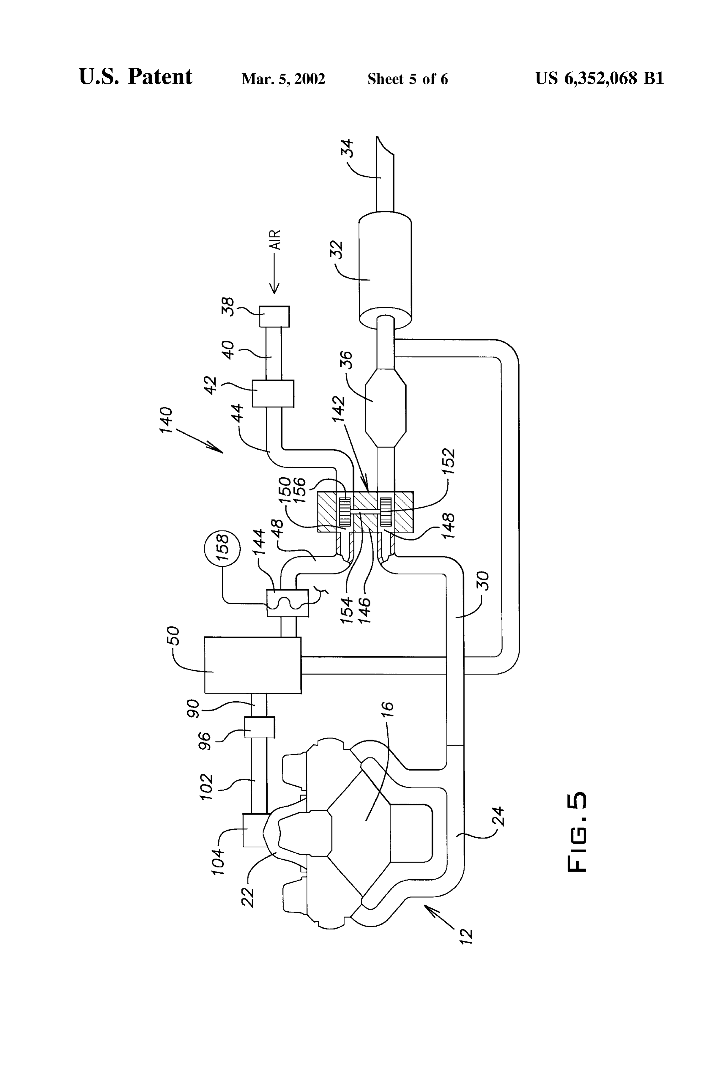
ment of the present invention. More specifically, FIG. 4 As described above, the first air filter 38, the air dryer 42, shows a fourth engine system 140, which is the same as the the PSA unit 50, the second air filter 96, and a pressurizing first engine system 10, except for the differences described unit Selected from the group consisting of the compressor below.
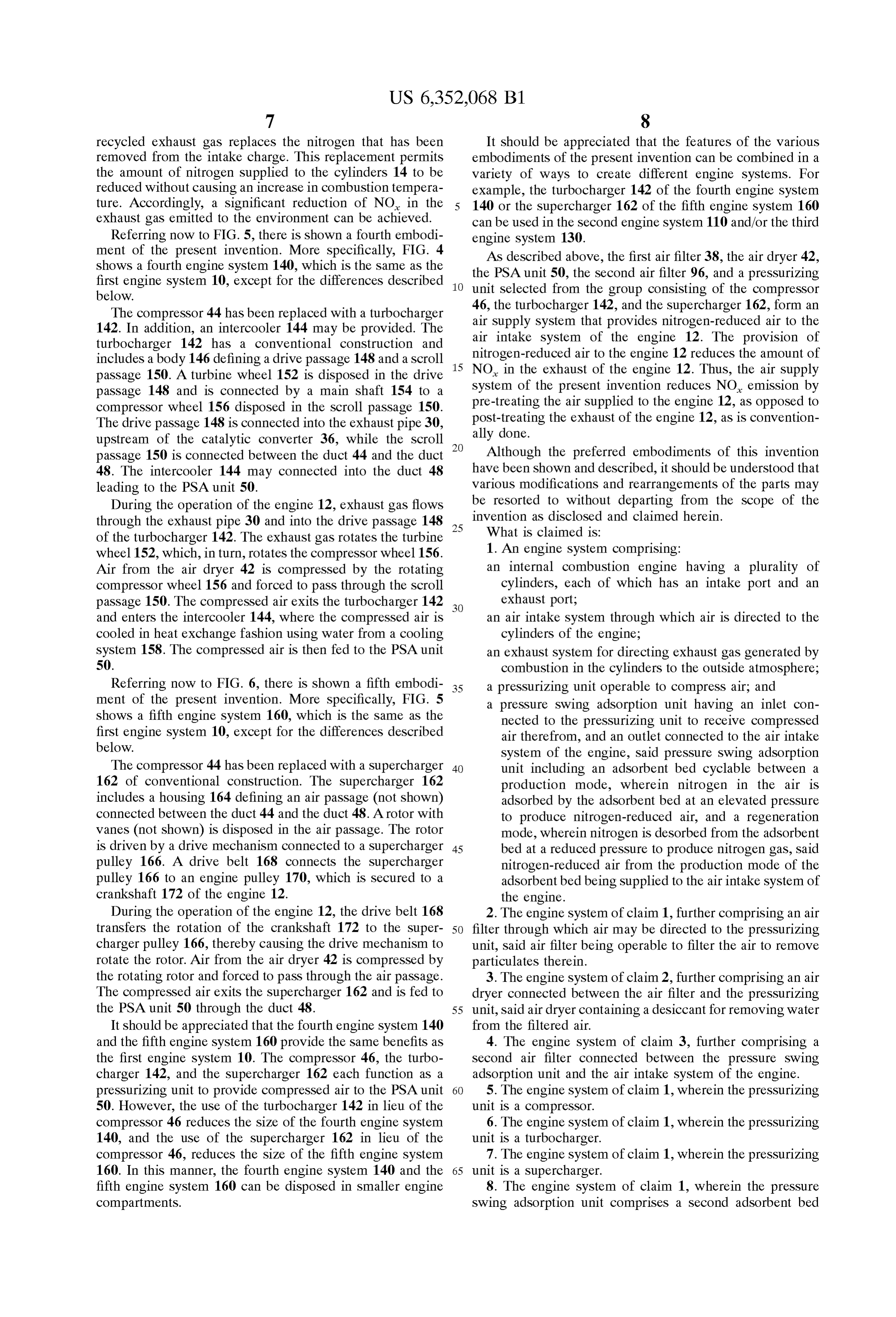
The compressor 44 has been replaced with a turbocharger 46, the turbocharger 142, and the Supercharger 162, form an 142. In addition, an intercooler 144 may be provided. The air intake System air Supply that provides nitrogen-reduced air to the turbocharger 142 has a conventional construction and nitrogen-reduced airofto the
System the engine 12. The provision of engine 12 reduces the amount of includes a body 146 defining a drive passage 148 and a scroll 15 passage 150. A turbine wheel 152 is disposed in the drive NO in the exhaust of the engine 12. Thus, the air supply passage 148 and is connected by a main shaft 154 to a System of the present invention reduces NO emission by compressor wheel 156 disposed in the scroll passage 150. pre-treating the air Supplied to the engine 12, as opposed to The drive passage 148 is connected into the exhaust pipe 30, post-treating ally done.
the exhaust of the engine 12, as is convention upstream of the catalytic converter 36, while the scroll passage 150 is connected between the duct 44 and the duct Although the preferred embodiments of this invention 48. The intercooler 144 may connected into the duct 48 have been shown and described, it should be understood that leading to the PSA unit 50. various modifications and rearrangements of the parts may During the operation of the engine 12, exhaust gas flows be resorted to without departing from the Scope of the through the exhaust pipe 30 and into the drive passage 148 25 invention
What is as disclosed and claimed herein.
claimed is:
of the turbocharger 142. The exhaust gas rotates the turbine 1. An engine System comprising: wheel 152, which, in turn, rotates the compressor wheel 156.
Air from the air dryer 42 is compressed by the rotating an internal combustion engine having a plurality of compressor wheel 156 and forced to pass through the scroll cylinders, each of which has an intake port and an passage 150. The compressed air exits the turbocharger 142 exhaust port;
and enters the intercooler 144, where the compressed air is an air intake System through which air is directed to the cooled in heat eXchange fashion using water from a cooling cylinders of the engine;
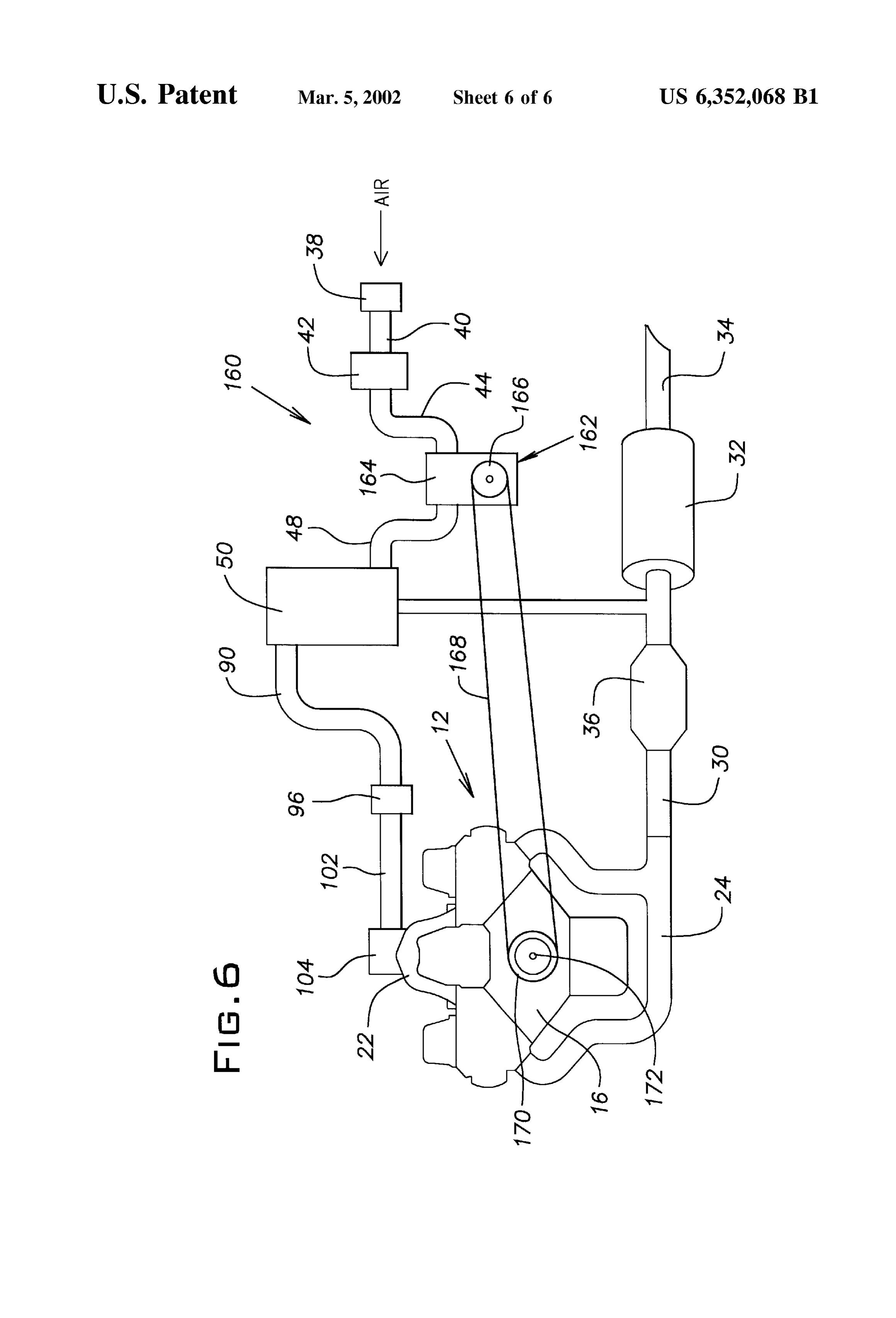
system 158. The compressed air is then fed to the PSA unit an exhaust System for directing exhaust gas generated by 50. combustion in the cylinders to the outside atmosphere; Referring now to FIG. 6, there is shown a fifth embodi 35 a pressurizing unit operable to compress air; and ment of the present invention. More specifically, FIG. 5 a pressure Swing adsorption unit having an inlet con shows a fifth engine system 160, which is the same as the nected to the preSSurizing unit to receive compressed first engine system 10, except for the differences described air therefrom, and an outlet connected to the air intake below. System of the engine, Said pressure Swing adsorption The compressor 44 has been replaced with a Supercharger 40 unit including an adsorbent bed cyclable between a 162 of conventional construction. The Supercharger 162 production mode, wherein nitrogen in the air is includes a housing 164 defining an air passage (not shown) adsorbed by the adsorbent bed at an elevated pressure connected between the duct 44 and the duct 48. A rotor with to produce nitrogen-reduced air, and a regeneration Vanes (not shown) is disposed in the air passage. The rotor mode, wherein nitrogen is desorbed from the adsorbent is driven by a drive mechanism connected to a Supercharger 45 bed at a reduced preSSure to produce nitrogen gas, Said pulley 166. A drive belt 168 connects the Supercharger nitrogen-reduced air from the production mode of the pulley 166 to an engine pulley 170, which is secured to a adsorbentbed being Supplied to the air intake System of crankshaft 172 of the engine 12. the engine.
During the operation of the engine 12, the drive belt 168 2. The engine System of claim 1, further comprising an air transfers the rotation of the crankshaft 172 to the Super 50 filter through which air may be directed to the preSSurizing charger pulley 166, thereby causing the drive mechanism to unit, Said air filter being operable to filter the air to remove rotate the rotor. Air from the air dryer 42 is compressed by particulates therein.
the rotating rotor and forced to pass through the air passage. 3. The engine System of claim 2, further comprising an air The compressed air exits the Supercharger 162 and is fed to dryer connected between the air filter and the preSSurizing the PSA unit 50 through the duct 48. 55 unit, Said air dryer containing a desiccant for removing water It should be appreciated that the fourth engine system 140 from the filtered air.
and the fifth engine system 160 provide the same benefits as 4. The engine System of claim 3, further comprising a the first engine system 10. The compressor 46, the turbo Second air filter connected between the pressure Swing charger 142, and the Supercharger 162 each function as a adsorption unit and the air intake System of the engine. preSSurizing unit to provide compressed air to the PSA unit 60 5. The engine System of claim 1, wherein the pressurizing 50. However, the use of the turbocharger 142 in lieu of the unit is a compressor.
compressor 46 reduces the Size of the fourth engine System 6. The engine System of claim 1, wherein the pressurizing 140, and the use of the Supercharger 162 in lieu of the unit is a turbocharger.
compressor 46, reduces the size of the fifth engine System 7. The engine System of claim 1, wherein the pressurizing 160. In this manner, the fourth engine system 140 and the 65 unit is a Supercharger.
fifth engine System 160 can be disposed in Smaller engine 8. The engine System of claim 1, wherein the pressure compartments. Swing adsorption unit comprises a Second adsorbent bed
Page 12
cyclable between a production mode, wherein nitrogen in an air dryer connected between the air filter and the the air is adsorbed by the second adsorbent bed at an preSSurizing unit, Said air dryer containing a desiccant elevated pressure to produce nitrogen-reduced air, and a for removing water from the filtered air; and regeneration mode, wherein nitrogen is desorbed from the a pressure Swing adsorption unit having an inlet con Second adsorbent bed at a reduced preSSure to produce nected to the preSSurizing unit to receive compressed nitrogen gas, and wherein Said nitrogen-reduced air from the air therefrom, and an outlet for connection to an air production mode of the Second adsorbent bed is Supplied to intake System of the engine, Said pressure Swing the air intake System of the engine. adsorption unit including an adsorbent bed cyclable 9. The engine system of claim 8, wherein when the between a production mode, wherein nitrogen in the air adsorbent bed is in the production mode, the Second adsor 1O bent bed is in the regeneration mode, and when the Second is adsorbed by the adsorbent bed at an elevated pressure adsorbent bed is in the production mode, the adsorbent bed to produce nitrogen-reduced air, and a regeneration is in the regeneration mode. mode, wherein nitrogen is desorbed from the adsorbent 10. The engine system of claim 9, wherein the first and bed at a reduced preSSure to produce nitrogen gas, Said Second adsorbent beds are each continuously cycled 15 nitrogen-reduced air from the production mode of the between the production mode and the regeneration mode adsorbent bed exiting the pressure Swing adsorption while the engine is running. unit through the outlet.
11. The engine System of claim 1, wherein the engine 20. The air supply system of claim 19, further comprising further comprises fuel injectors for the cylinders, and a Second air filter connected to the outlet of the pressure wherein the air intake System comprises an intake manifold Swing adsorption unit.
for Supplying air to the intake ports of the cylinder, and an 21. The air Supply System of claim 19, wherein the air header for Supplying air to the fuel injectors. preSSurizing unit is a compressor. 12. The engine System of claim 11, wherein the nitrogen 22. The air Supply System of claim 19, wherein the reduced air from the pressure Swing adsorption unit is preSSurizing unit is a turbocharger.
Supplied to the air header. 25 23. The air supply system of claim 19, wherein the 13. The engine System of claim 11, wherein the nitrogen preSSurizing unit is a Supercharger.
reduced air from the pressure Swing adsorption unit is 24. The air Supply System of claim 19, wherein the Supplied to the intake manifold. adsorbent bed is comprised of Zeolites. 14. The engine System of claim 13, wherein the nitrogen 25. A method of reducing NO in the exhaust of an reduced air from the pressure Swing adsorption unit is also
Supplied to the air header. internal combustion engine, Said method comprising the 15. The engine System of claim 1, further comprising an Steps of exhaust gas recirculation duct connected between the (a) providing an adsorbent bed; exhaust System and the air intake System, said exhaust gas (b) pressurizing air;
recirculation duct being adapted to convey exhaust gases 35 (c) passing the pressurized air through the adsorbent bed, into the air intake System for mixing with the nitrogen thereby raising the pressure of the adsorbent bed and reduced air from the pressure Swing adsorption unit. causing the adsorbent bed to adsorb nitrogen from the 16. The engine System of claim 15, further comprising a air to produce nitrogen-reduced air; control valve disposed in the exhaust gas recirculation duct, said control valve being operable to control the flow of 40 (d) directing the nitrogen-reduced air into an air intake exhaust gas through the exhaust gas recirculation duct. System of the engine;
17. The engine system of claim 1, wherein the adsorbent (e) reducing the pressure in the adsorbent bed Such that bed is comprised of Zeolites. nitrogen desorbs from the adsorbent bed; and 18. The engine System of claim 1, wherein the preSSure
Swing adsorption unit further comprises three other adsor 45 26. directing
The the nitrogen out of the adsorbent bed.
method of claim 25, further comprising the step bent beds.
of directing exhaust gas into the air intake System of the 19. An air Supply System for an internal combustion engine for mixing with the nitrogen-reduced air from the engine, Said air Supply System comprising: adsorption bed.
a pressurizing unit operable to compress air; 27. The method of claim 25, wherein steps (c) through (f) an air filter through which air may be directed to the 50 are continuously repeated while the engine is running. preSSurizing unit, Said air filter being operable to filter the air to remove particulates therein; k k k k k
Provenance
- Collection
- Cited prior art
- Original PDF
- patentimages.storage.googleapis.com →
- Filed
- 1999-12-27
- Pages
- 12
- Method
- pdftotext (the PDF's own text layer) + pdftoppm 300dpi page scans
- Source
- Google Patents bibliographic record
- Granted
- 2002-03-05
- Inventors
- Arthur J. Jacobsen; Honda Motor Co Ltd
- Transcribed from
- patentimages.storage.googleapis.com →