patent · US5226400
Device for conversion of liquid fuel into fuel vapor and microscopic liquid droplets
13 July 1993
Page 1 — bibliographic record
United
Birch
States Patent (19) 11 Patent Number: 5,226,400
(54) DEVICE FOR CONVERSION OF LIQUID Attorney, Agent, or Firm-Fields, Lewis, Pittenger & FUEL INTO FUEL WAPOR AND Rost
MICROSCOPIC LIQUID DROPLETS
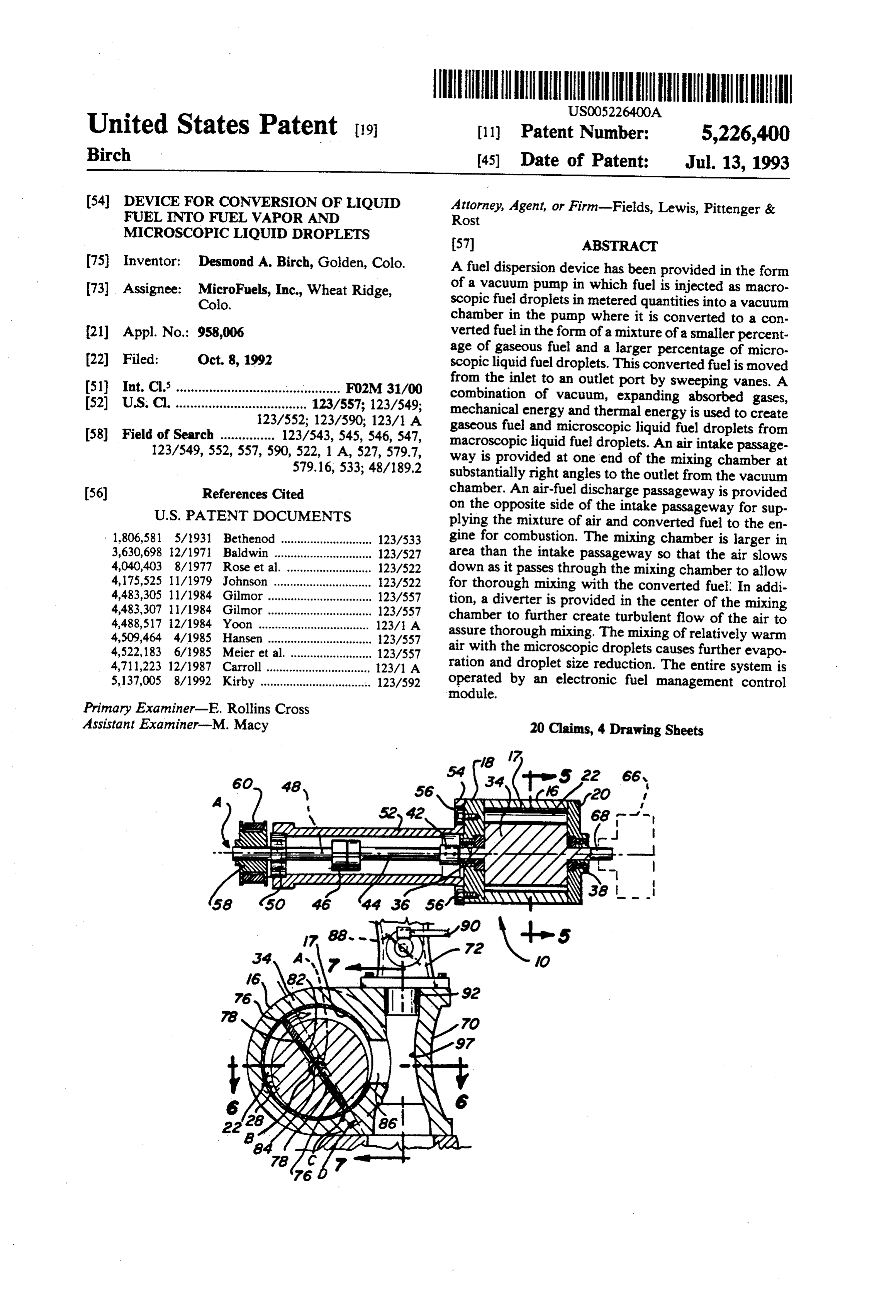
(75) Inventor: Desmond A. Birch, Golden, Colo. A fuel dispersion device has been provided in the form 73) Assignee: MicroFuels, Inc., Wheat Ridge, of a vacuum pump in which fuel is injected as macro Colo. scopic fuel droplets in metered quantities into a vacuum chamber in the pump where it is converted to a con 21 Appl. No.: 958,006 verted fuel in the form of a mixture of a smaller percent age of gaseous fuel and a larger percentage of micro 22) Filed: Oct. 8, 1992 scopic liquid fuel droplets. This converted fuel is moved 51) Int. Cl. .............................. ... . . . . . . . . . . . . F02M 31/00 from the inlet to an outlet port by sweeping vanes. A 52) U.S. Cl. .......... ... 123/557; 123/549; combination of vacuum, expanding absorbed gases, 123/552; 123/590; 123/1 A mechanical energy and thermal energy is used to create 58) Field of Search ............... 123/543, 545, 546, 547, gaseous fuel and microscopic liquid fuel droplets from 123/549, 552, 557, 590, 522, 1A, 527, 579.7, macroscopic liquid fuel droplets. An air intake passage 579.16, 533; 48/189.2 way is provided at one end of the mixing chamber at substantially right angles to the outlet from the vacuum (56) References Cited chamber. An air-fuel discharge passageway is provided
on the opposite side of the intake passageway for sup plying the mixture of air and converted fuel to the en 1,806,581 5/1931 Bethenod ............................ 123/533 gine for combustion. The mixing chamber is larger in 3,630,698 12/1971 Baldwin .............................. 123/527 area than the intake passageway so that the air slows 4,040,403 8/1977 Rose et al. .......................... 123/522 down as it passes through the mixing chamber to allow 4,175,525 11/1979 Johnson .............................. 123/522 for thorough mixing with the converted fuel. In addi 4,483,305 11/1984 Gilmor ................................ 123/557 tion, a diverter is provided in the center of the mixing 4,483,307 11/1984 Gilmor ................................ 123/557 chamber to further create turbulent flow of the air to 4,488,517, 12/1984 Yoon ..... ... 123/1 A assure thorough mixing. The mixing of relatively warm 4,509,464 4/1985 Hansen ................................ 123/557 4,522, 183 6/1985 Meier et al. ........................ 123/557 air with the microscopic droplets causes further evapo 4,711,223 12/1987 Carroll ................................ 123/1 A ration and droplet size reduction. The entire system is 5,137,005 8/1992 Kirby ................................... 123/592 operated module.
by an electronic fuel management control
Primary Examiner-E. Rollins Cross
Assistant Examiner-M. Macy 20 Claims, 4 Drawing Sheets
A. \
(Mgarrieset 22€.N.
ZZZZZ ZzZ24N VVVVVS
Page 2
Drawing sheet — no readable text.
Page 3
Drawing sheet — no readable text.
Page 4
Drawing sheet — no readable text.
Page 5
Drawing sheet — no readable text.
Page 6
DEVICE FOR CONVERSION OF LIQUID FUEL
reservoir to vaporize the fuel whereupon it is fed into a manifold of an engine which is supplied with still an
INTO FUEL VAPOR AND MICROSCOPIC LIQUID additional air intake. Heat exchange means are provided
DROPLETS
around the reservoir and again near the intake manifold
TECHNICAL FIELD to minimize fluctuations in fuel temperature. Because the system is open, large quantities of air are drawn
This invention relates to a device for converting liq through it making it very difficult to draw a sufficient uid fuel into fuel vapor and microscopic liquid fuel vacuum to substantially vaporize any fuel which is not particles prior to introduction into an intake manifold of 10 vaporized directly by the carburetor. In other words, an internal combustion engine. More particularly, the for such a device to operate effectively it would be invention relates to the injection of macroscopic liquid necessary to provide such a huge vacuum pump that the fuel droplets into a rotary vane vacuum chamber fuel savings, if any, would be negligible. Alternatively, wherein some of the macroscopic liquid fuel droplets with a smaller vacuum pump the fuel is not properly are converted to a gaseous fuel and the rest are con vaporized in an open system because atmospheric air is verted to microscopic liquid fuel droplets. After dis 15 constantly being drawn into the system. charge from the vacuum chamber the gaseous fuel and Another device for providing gaseous fuel to the microscopic liquid fuel droplets are mixed with air and carburetor of an internal combustion engine is shown in supplied to the intake manifold of the internal combus U.S. Pat. No. 3,630,698 to Joseph H. Baldwin for "Fuel tion engine. System'. In this device, gaseous vapors are drawn from BACKGROUND ART a vacuum chamber by means of a manifold vacuum. The vacuum chamber contains a supply of liquid fuel
It is well understood that the greater the vaporization which or gasification of liquid fuel that can be accomplished is replenished through a float valve. Two poten the greater the surface area of the fuel which is subject tial problems are associated with this type of device. First, the vacuum from the manifold may not be suffi to oxidation and therefore the higher the rate of com 25 cient under certain load conditions to provide sufficient bustion. Many individuals working in the field felt that fuel to the engine. Second, by drawing the gaseous if complete conversion of the fuel to the gaseous state could be accomplished, a highly efficient clean operat vapors off of a body of liquid gasoline the lighter hydro ing engine could be provided. Attempts to completely carbons are boiled off first, leaving a relatively heavy gasify liquid hydrocarbon fuel go back many years. 30 liquid hydrocarbon, frequently referred to as "strip oil'. However, all of these attempts have had significant Therefore, in order to keep them working properly, shortcomings. In some instances, the devices did not means must be provided to regularly withdraw the strip completely vaporize the fuel and therefore the expected oil and replace it with fresh gasoline. increase in efficiency did not materialize. In other cases, Another device for vaporizing gasoline is disclosed in the devices were of such a complex nature as to negate 35 U.S. Pat. No. 4,040,403 to Rose, et al. for “Air Fuel any real benefit from them or require such high power Mixture Control System". In this device, fuel is sup inputs themselves that even though a greater fuel eff plied to a vaporizer wherein the level of the liquid fuel ciency was realized, the increased power needs negated in the vaporizer is controlled by a float valve. Hot ex this benefit. The complete conversion of fuel to vapor haust gases from the engine are boiled through the liq created another unexpected problem. Although the fuel uid gasoline causing a portion of it to be vaporized and would rapidly and completely burn, it was discovered carried to the engine. The device includes a complex that the expansion of the fuel in forming a gas occurred amplifying system for adjusting the air-fuel mixture and too early. Therefore, the density of the fuel, when a separator for taking out any fuel droplets from the fuel mixed with air was so low that not enough fuel could be as it is vaporized in the vaporizer. With this device, the directed into the combustion chambers of the engine to lighter hydrocarbons will be vaporized leaving behind generate power equal to other state of the art devices the heavier hydrocarbons or strip oil. such as carburetors, throttle body injection systems or U.S. Pat. No. 4,175,525 to Johnson for "Fuel Vapor direct port injection systems. izer System. For Internal Combustion Engines' dis One of the most noted prior art devices which was closes a sealed vaporization system connected between developed by Charles Nelson Pogue in the 1930s was a a fuel supply line and the intake manifold of an internal carburetor for the vaporization of gasoline which has combustion engine and operated in parallel with a car been widely advertised as the "two hundred mile per buretor. A float valve is provided in this device to con gallon carburetor'. This device has never enjoyed wide trol the flow of liquid fuel to a chamber wherein it is commercial success because it is nearly as large and vaporized and fed to a carburetor. The lighter hydro cumbersome as the engine it is meant to fuel and it 55 carbons will be boiled off the liquid fuel before the requires an operating temperature which approaches heavier hydrocarbons, leaving strip oil in the chamber. the flash point of the fuel, such as gasoline, so that the Additional devices for vaporizing fuel are disclosed potential for an explosion is quite great. in U.S. Pat. No. 4,483,305 for "Fuel Vaporization De A device for vaporizing fuel, such as diesel fuel is vice" to James E. Gilmor and U.S. Pat. No. 4,483,307 disclosed in U.S. Pat. No. 1,806,581 to Bethenod for for "Fuel Vaporization Device For Internal Combus "Fuel Supply System For Internal Combustion Engines tion Engine', also to James E. Gilmor. These devices of Variable Load For Using Heavy Fuels'. The diesel are designed to instantaneously vaporize all of the fuel. fuel is supplied through a conventional gasoline carbu U.S. Pat. No. 4,522,183 to Meier et al. for “Method retor and air is drawn through an intake by means of a For Converting a Retrograde Substance to the Gaseous vacuum pump. This system is an open system, i.e., air in 65 State" is directed to a method wherein the fuel is pre large quantities is continuously drawn in from the atmo pressurized and heated and the pressure released for sphere by a first vacuum pump. A second vacuum pump abruptly converting a retrograde fuel to a gaseous state. is intended to pull a vacuum on the air-fuel mixture in a While the method may be effective to accomplish its
Page 7
intended result, it is not believed that sufficient fuel can mounted in the cylindrical wall of the housing in the be provided to an internal combustion engine by the same angular relationship. The converted fuel outlet practice of this method to operate it satisfactorily, par extends through the cylindrical wall of the vacuum ticularly under load. . chamber into communication with an air-fuel mixing The ultimate carburetion system would be one in chamber just upstream of the near contact line. which a small percentage of the fuel is vaporized and The fuel injectors inject macroscopic droplets of the rest of the fuel is converted to microscopic liquid liquid fuel through the inlets into the vacuum chamber fuel droplets prior to introducing the fuel into the intake where it is converted to microscopic fuel and vaporized manifold of an internal combustion engine. When mixed fuel. This is accomplished by a combination of vacuum, with air in the manifold the vaporized fuel and the mi 10 expanding absorbed gases and water vapor in the mac croscopic fuel droplets disperse with some additional roscopic fuel droplets, and mechanical and heat energy vaporization. from the action of the vacuum pump. For convenience, gaseous fuel will be referred to as An air plenum has an air-fuel mixing chamber con “vapor" or "vaporized fuel"; liquid fuel droplets of a nected to the vacuum pump outlet port for receiving size not visible with the naked eye, under normal light 15 and mixing ing conditions, will be referred to as "microscopic' through an airtheinletconverted port in the fuel with air introduced air plenum. An air intake particles or droplets and liquid fuel droplets of a size which is visible with the naked eye will be referred to as passageway connects at one end of the mixing chamber to the air inlet port and is at substantially right angles to "macroscopic" droplets. Ideally, macroscopic liquid the converted fuel outlet from the vacuum chamber. An fuel droplets from a suitable source, such as one or more 20 air-fuel discharge passageway is provided on the oppo fuel injectors, are converted to a mixture consisting of a small percentage of fuel vapor and a large percentage of site side of the intake passageway for supplying the microscopic fuel droplets. This mixture will be referred mixture of air and converted fuel to the manifold and to as "converted fuel'. then to the engine for combustion. The mixing chamber 25 is larger in area than the intake passageway so that the
DISCLOSURE OF THE INVENTION air slows down as it passes through the mixing chamber In accordance with the present invention, a device creating a tumbling effect to allow for thorough mixing for converting a combustible liquid fuel into converted with the converted fuel. In addition, a diverter is pro fuel having a smaller proportion of vapor and a larger vided in the center of the mixing chamber to further proportion of microscopic fuel droplets, mixing the 30 create turbulent flow of the air to assure thorough mix converted fuel with air in a manifold to convert more of 1ng.
the converted fuel to a vapor and transferring the con From the foregoing, the advantages of this invention verted fuel and air mixture into a combustion chamber are readily apparent. A very simple, and therefore eco is provided. The device includes a vacuum chamber nomical, device has been provided for converting mi formed as a cylindrical housing wall having a longitudi 35 croscopic liquid fuel particles into converted fuel hav nal axis with at least one fuel inlet in the housing wall ing the proper ratio of vaporized fuel and microscopic and a fuel outlet in the housing wall offset from the fuel particles. By use of vacuum, expanding absorbed inlet. An eccentrically mounted cylindrical rotor is gases, mechanical energy and thermal energy the con provided within the housing wall for rotation about a verted fuel is formed. The converted fuel is mixed with longitudinal axis about bearings mounted in opposite 40 air in a novel mixing chamber which causes thorough end walls. The rotor has a plurality of radial slots and a mixing with some additional evaporization and droplet generally rectangular vane slidably received in each of breakup. Thus, the combustion of the fuel in the engine the slots. The vanes are urged outwardly against the will be enhanced, thereby minimizing the amount of housing wall when the rotor is rotated. unburned hydrocarbons and maximizing fuel economy. For lubrication the inner surface of the housing may 45 By utilizing a lubricous material, the problems of lubri. be coated with a lubricous material. This may be a poly cating the parts in a fuel-rich vacuum environment, tetrafluoroethylene (PTFE) matrix such as Teflon (R). wherein the lubricant would be dissolved and may va Alternatively a sleeve may be used inside of the housing porize, is minimized.
which is made of a polyamid, such as Torlon (R). The Additional advantages will become apparent from vanes are made of a polyamide having a durometer or the description which follows, taken in conjunction hardness which is less than that of the lining. If desired, with the accompanying drawings.
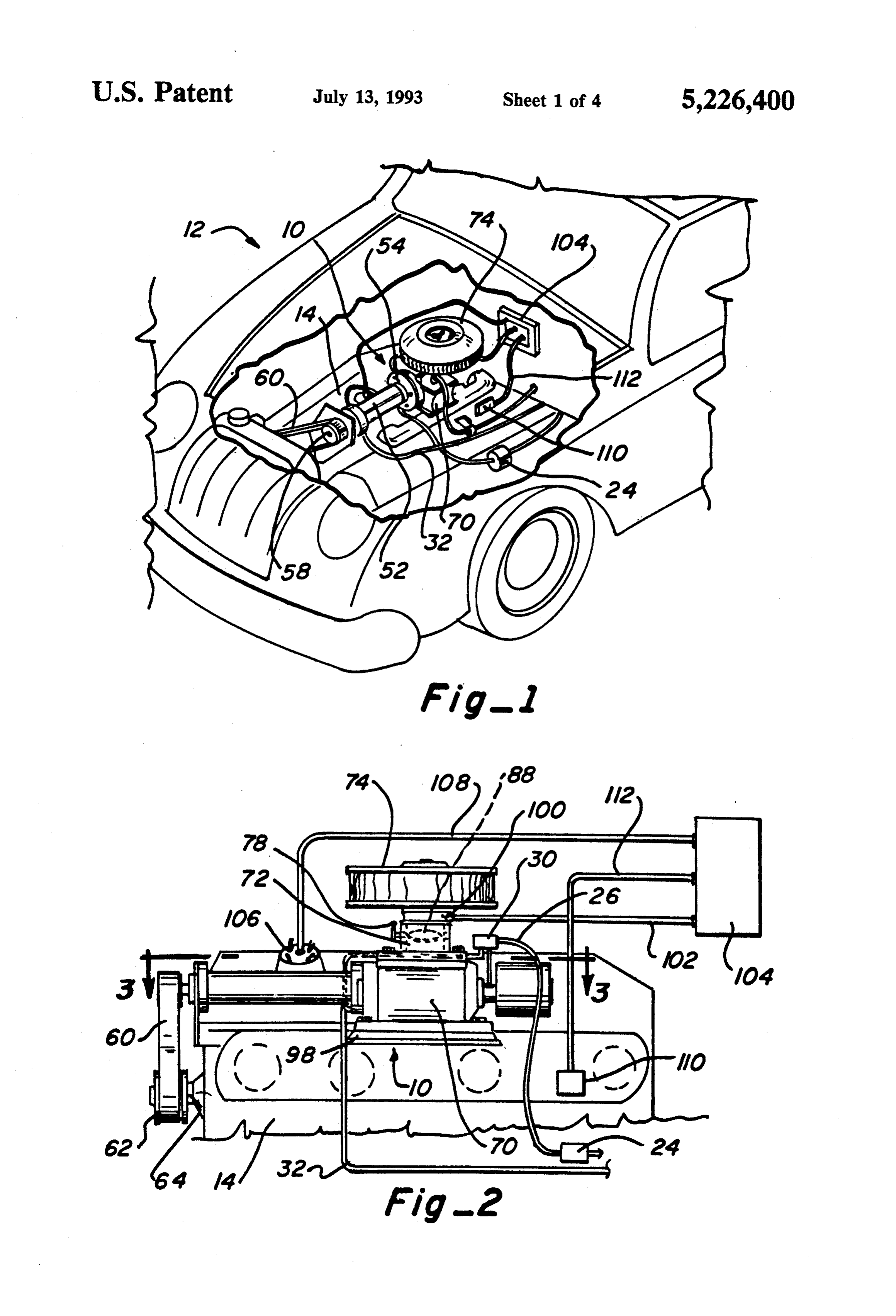
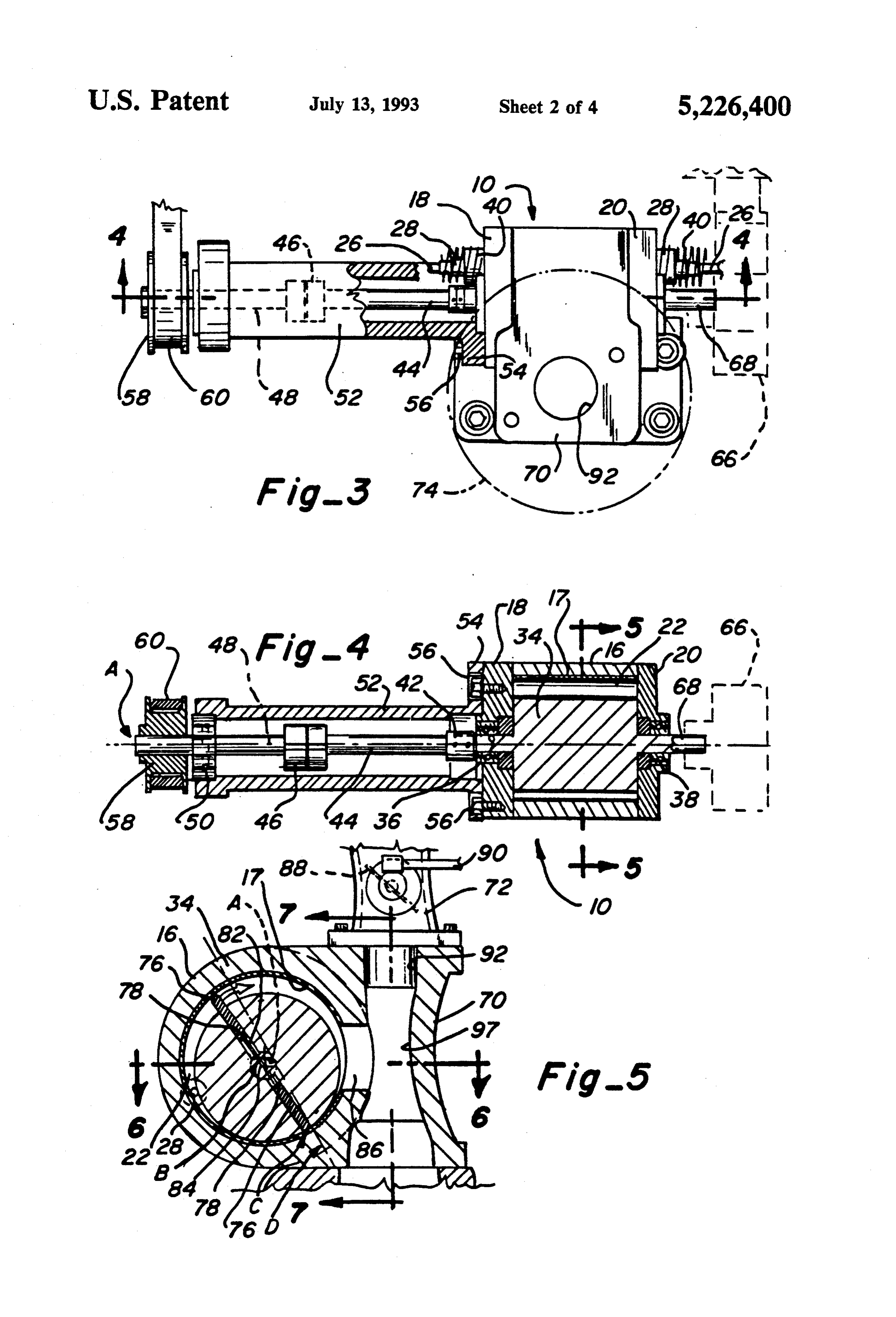
spring means can be provided for urging the vanes outwardly against the housing wall. The vanes are ar BRIEF DESCRIPTION OF THE DRAWINGS ranged in opposing relationship and the spring means FIG. 1 is a fragmentary perspective view of a vehicle can include a pin positioned between opposite springs to 55 having the fuel conversion device of this invention urge the vanes against the housing wall. installed therein;
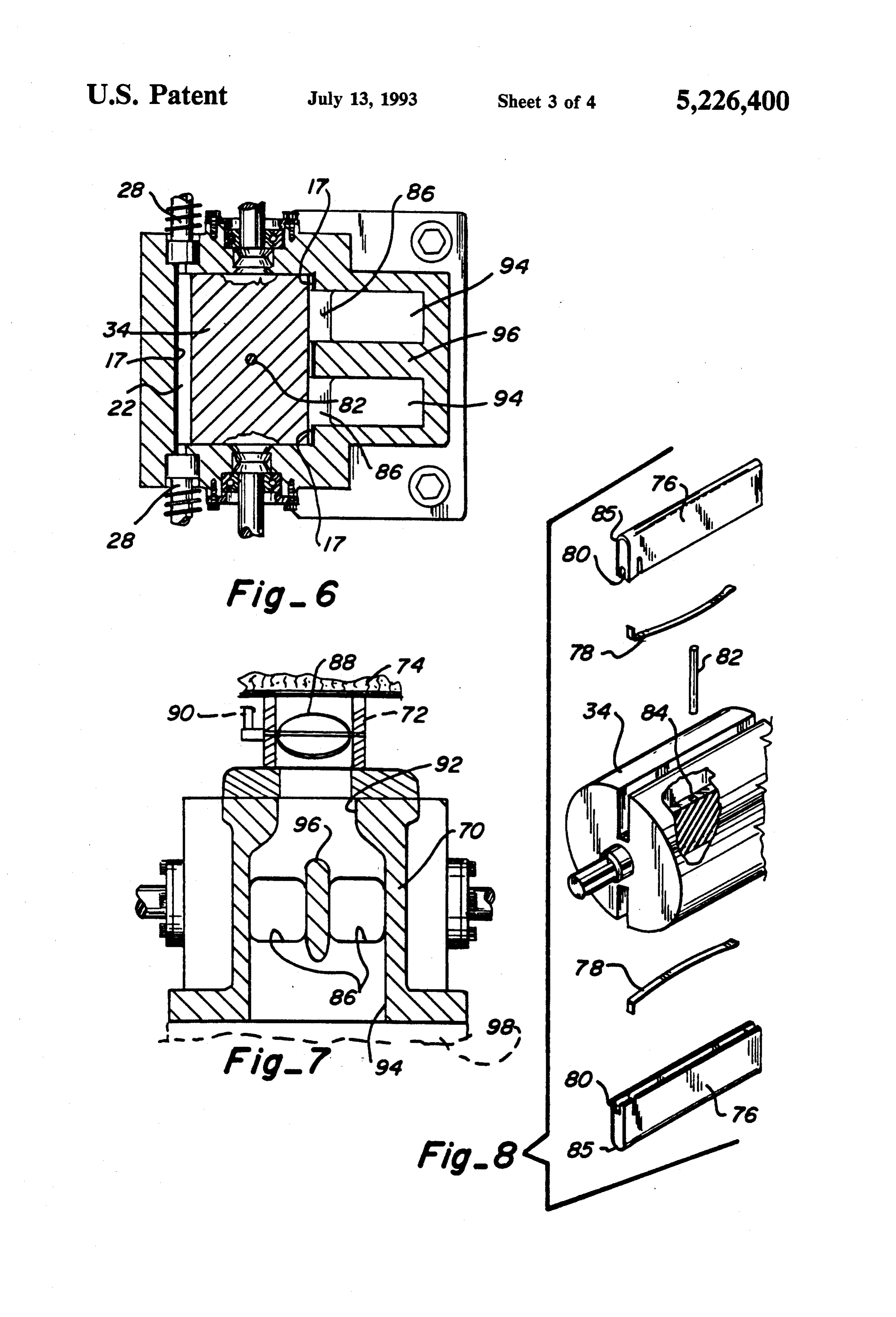
More particularly, the rotor has a surface which FIG. 2 is an enlarged side elevation of the fuel con comes into near contact, e.g., within two-thousandth of version device of this invention connected to the intake an inch, with the cylindrical wall along a near contact manifold of an internal combustion engine; line lying in a common plane with the axis of the rotor 60 FIG. 3 is an enlarged horizontal section, taken along to form a vacuum chamber between the rotor and the line 3-3 of FIG. 2, showing the fuel converter of this cylindrical wall. A liquid fuel inlet in the form of a fuel invention and associated drive mechanism therefor; injector can be mounted through each end wall in op FIG. 4 is a horizontal section, taken along line 4-4 of posing relationship with each other. The injectors are FIG. 3, showing details of a one-way clutch and bearing angularly spaced within the vacuum chamber to the 65 mounts for the fuel converter;
upstream side of the plane and as close to the near contact line as the introduction of fuel through the lineFIG. 5 is an enlarged horizontal section, taken along 5-5 of FIG. 4, showing details of the air-fuel mix injectors will permit. Alternatively, the injectors can be ing chamber and rotor;
Page 8
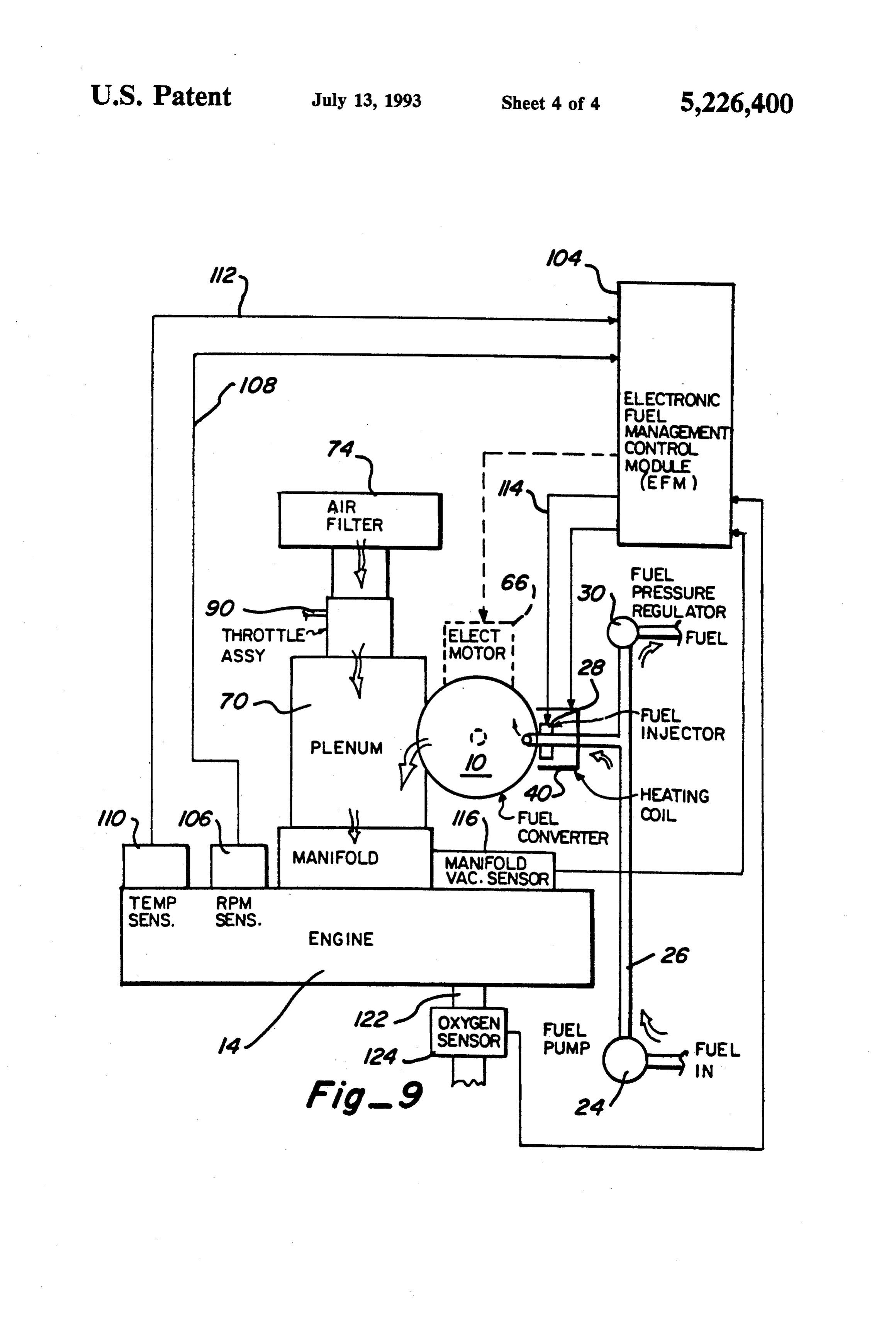
FIG. 6 is a horizontal section, taken along line 6-6 of verter 10 at sufficient speed to create sufficient vacuum FIG. 5, showing additional details of the mixing cham to convert the fuel from macroscopic liquid droplets to ber and rotor; vapor and microscopic liquid particles at a sufficient FIG. 7 is a vertical section, taken along line 7-7 of rate to start the engine. Therefore, if required, an elec FIG. 5, showing further details of the mixing chamber; tric motor 66 can be mounted behind the fuel converter FIG. 8 is an exploded view of the rotor showing the 10 which will be operated directly off the battery (not vanes and associated parts; and shown) to drive the rotor through a stub shaft 68 con FIG.9 is a diagrammatical view of the fuel converter nected thereto at a much higher speed so that enough of this invention connected to an internal combustion fuel will be converted and supplied to the engine to start engine, showing typical electronic sensing devices to 10 it. This is possible because one-way clutch 46 allows control the fuel converter. driven shaft 44 and rotor 34 to turn faster than drive BEST MODE FOR CARRYING OUT THE shaft 48. By way of example, electric motor 66 may NVENTION rotate rotor 34 at 750 rpm or more while the engine is turning at 150 rpm during starting. After starting, elec
As illustrated in FIG. 1, the fuel converter 10 of this 15 tric motor 66 will be turned off and the engine and rotor invention is installed in a vehicle 12 adjacent the engine will rotate at the same speed.
14. The fuel converter includes a generally cylindrical housing 16 having a longitudinal axis A and opposed berAfter conversion, the fuel passes from vacuum cham 22 into a plenum 70 where it is mixed with air sup front end plate 18 and rear end plate 20, as shown in plied through conduit 72 so that the air flow is at right FIG.4, to form a vacuum chamber 22. Suitable lubrica 20 tion within the vacuum chamber is a problem. Liquid angles to the converted fuel to assure maximum mixing as more fully described below. Conveniently, the air is lubricants, i.e., oils and greases, will not work because drawn through a filter 74, connected to the other end of they will be dissolved and removed by the fuel and will conduit 72.
tend to evaporate, particularly when gasoline is used as Turning now to FIGS. 5-9, the rotor 34 has a plural a fuel because of the higher temperatures. To overcome 25 ity of vanes, such as two opposed vanes 76 which are this, the housing has a lining 17 made from a lubricous urged apart as by a pair of leaf springs 78 received in material, such as a polyamide. One such polyamide recesses 80 of the vanes. A pin 82 has opposite ends which is suitable is Torlon (R). Alternatively, a PTFE bearing against leaf springs 78 and reciprocated within coating, such as a Teflon (R) matrix can be used. Fuel is passageway 84 extending through rotor 34 between supplied by means of a fuel pump 24 through a fuel line 30 vanes 76. The vanes are coated with the same lubricous 26 to fuel atomizing devices, such as fuel injectors 28. A material as the housing liner, but having a lesser hard fuel pressure regulator 30 is located in return fuel line 32 ness or durometer than the housing liner. This assures for returning fuel which is not used by the fuel injectors that most of the wear that occurs will be along the edge to the fuel tank (not shown). of the vanes, which can be easily replaced. As can be Rotor 34, shown in FIG. 4, is journaled in a front 35 seen, with rotor 34 mounted for rotation eccentrically bearing 36 mounted in front end plate 18 and a rear with respect to housing 16, the vanes will be urged bearing 38 mounted in rear end plate 20. The rotor is against the inner surface of the housing but will move mounted for rotation about a longitudinal axis. A spaced reciprocally back and forth as the rotor rotates. Since laterally from housing axis B, as best seen in FIGS. 4 the spacing of the two vanes remains substantially con and 5. The rotor makes near contact with the housing 40 stant, there will be little flexure of springs 78 and there wall 16 along line C. In one form of the invention, the fore the chance of failure of the springs through ex spacing along line C is approximately one-thousandth of tended use is very minimal. In fact, when the pump is in an inch. Conveniently, the heat generated by these bear operation centrifugal force will hold the vanes out ings during operation of the fuel converter 10 will heat wardly. However, for starting purposes it is desirable to the end plates and the respective injectors 28 to preheat 45 have the springs in place to keep the vanes extended. the fuel before it passes into vacuum chamber 22. Also, heating coils 40 can be provided around each fuel injec With the use of starter motor 66, for most applications springs 78 and pin 82 will not be needed since the cen tor 28 to pre-heat the fuel for cold starts when the ambi trifugal force on the vanes created when motor 66 is ent temperature is extremely low. Alternatively, heat energized will be sufficient. ing coils (not shown) could be provided in the walls or The fuel injected into vacuum chamber 22 as macro ends of vacuum chamber 22 to reheat the fuel. The scopic liquid fuel droplets is converted to vapor and injectors 28 lie on the upstream side of a plane D formed microscopic fuel particles which are moved around the by axis A and line C and as near to line C as is possible chamber by the vanes and discharged through a pair of and still inject the fuel. The reason for this is so the fuel outlet ports 86, located downstream of plane D. remains in the vacuum chamber as long as possible to 55 As best understood at the present time, a number of more greatly facilitate the formation of converted fuel. forces act upon the macroscopic liquid fuel droplets The rotor 34 is connected by coupling 42 to a driven introduced by the fuel injectors. These are: shaft 44. The forward end of driven shaft 44 is con 1. Vacuum, which is a direct result of the vacuum nected through a one-way slip clutch 46 to a drive shaft environment of the device, causes rapid vaporization of 48. This drive shaft is supported in bearing 50 at the 60 fuel from the surface of the droplets thereby causing forward end of cylindrical housing 52. The other end of some reduction in the sizes of all droplets. housing 52 is provided with a flange 54 attached to front 2. Absorbed gas expansion, which also is a direct end plate, as by bolts 56 spaced around the periphery result of the vacuum environment of the device, caused thereof. Drive shaft 48 is driven by pulley 58 which in absorbed gases such as nitrogen, oxygen, water vapor turn is driven by belt 60 driven from pulley 62 attached 65 and other atmospheric gases to expand within the mac to pully shaft 64 of engine 14, as best seen in FIG. 2. roscopic droplets blowing them apart into smaller mi During cold weather, the generator or alternator of croscopic droplets thereby exposing more surface area the vehicle may not turn the engine and the fuel con for further boiling off of liquid fuel from the micro
Page 9
scopic droplets. Evaporization alone is not sufficient to gine is initially started. A suitable system has been cause both significant vaporization and droplet size found, an engine management system manufactured by reduction, particularly with less volatile fuels such as Digital Fuel Injection Incorporated at 37732 Hills Tech alcohols and alcohol mixtures. The vaporization is a Drive, Farmington Hills, Mich. 48331, which has exter self-limiting process because the evaporation process nal program capabilities to adjust fuel ratio across the absorbs heat from the droplets which rapidly reduces entire range, for various fuels. Also, most original their temperatures such that the evaporation rate rap equipment automobile manufacturers' management sys idly decreases to an insignificant level. The absorbed tems can be modified to manage the fuel converter of atmospheric gases and most volatile species of the fuel this invention.
rapidly expand causing eruptive boiling of the droplets 10 Additionally, a manifold vacuum sensor 116 is con breaking them into much smaller droplets. nected to control module through wire 118 and an oxy 3. Mechanical energy from vanes, rotor and housing gen sensor 120 on engine tailpipe 122 is connected by agitate the macroscopic liquid droplets to distort and wire 124 to control module 104. Many other sensors spread them out and break the surface tension within (not shown) may be provided to measure other engine the droplets to further release absorbed gases. 15 conditions or functions for electronic fuel management. 4. Heat energy from contact with vanes, rotor and As of the date of this application, applicant's fuel housing raises the temperature of liquid droplets to conversion device has only been operated at an eleva enhance vaporization and expansion and release of ab tion of approximately five-thousand feet above sea sorbed gases. level. Thus, the parameters set forth below are for this The foregoing explanation is believed to be accurate, 20 elevation and would vary at either higher or lower to the extent that the forces acting upon the fuel drop elevations in accordance with well-known physical lets are understood at the present time. However, it laws. In a fuel conversion device wherein the vacuum should be understood that there may be additional forces acting on the droplets and/or the magnitude of chamber interior 22 is formed within housing 16 which has an diameter of 2.60 inches and a length of 3.00 the effect of the forces described above may be greater 25 inches and the diameter of rotor 34 is 2.50 inches. When or lesser than presently understood. the rotor is rotating at an idle speed of between 700 and Turning to FIG. 7, air flows through conduit 72 past 750 rpm, the device draws approximately 24.5 inches of a butterfly valve 88 controlled through a butterfly link mercury at an ambient temperature of 80' F. before age 90 connected to the accelerator (not shown). This introduction of fuel. At operating speeds between 1700 intake air passes through a throat 92 in plenum 70 and 30 and 2000 rpm, after fuel is introduced in sufficient quan into a larger mixing chamber 94 which includes outlet tity to operate the engine at these speeds, the device ports 86 from vacuum chamber 22 and also a center stabilized at 23.5 to 23.7 inches of mercury. At these dividing wall 96 between outlet ports 86 and curved speeds and at ambient temperatures of between 45 F. wall 97 opposite ports 86. Thus, as the air moves from and 80 F., the device will produce at the outlet con throat 92 into larger chamber 94, its flow will slow 35 verted fuel, a smaller portion of which is vapor, and a down. The dividing wall 96 and curved wall 97 cause larger portion of which is microscopic liquid droplets. turbulence in the air so that it mixes thoroughly with As the microscopic fuel droplets move through the the gaseous fuel and microscopic fuel particles being vacuum chamber, the mixing chamber and the mani discharged into chamber 94 from discharge openings 86 fold, additional microscopic fuel droplets are vaporized which are at right angles to the flow of air through as previously described.
chamber 94. The relatively warm air which is mixed By way of example, vacuum chamber 22, of the size with the fuel will heat the microscopic fuel droplets described above, is connected to mixing chamber 94, causing additional evaporation and droplet size reduc wherein throat 92 has a diameter of 1.50 inches and an tion. By injecting the converted fuel into the air at right outlet into the manifold of 1.90 inches. The outlet ports angles, good mixing of the air and fuel is assured which 45 86 which communicate the vacuum chamber with the will improve the burning of the fuel in the cylinders of mixing chamber each are 1.0625 inches wide by 1.375 the engine. Thus, a very efficient and clean burn is inches high. The dividing wall 96 is 1.9375 inches long assured. and 0.50 inches wide.
Asbest seen in FIG.9, an electronic fuel management The invention has been described as utilizing a single (EFM) control module 104 is provided. This control vacuum pump with an engine. However, it is contem module receives various signals from RPM sensor 106 plated that a very small vacuum pump could be used to mounted on engine 14 through a wire 108. A tempera supply fuel to each cylinder to the engine for some ture sensor 110 on engine 14 provides a signal through applications.
wire 112 to the control module. The control module processes these signals and provides a signal through 55 areFrom the foregoing, the advantages of this invention wire 114 to fuel injectors 28, which provides fuel to the vided in theapparent.
readily form of a
A fuel converter has been pro vacuum pump into which liquid converter in accordance with the parameters sensed by fuel is injected in the form of macroscopic liquid parti the control module. Thus, if butterfly valve 88 is opened cles in metered quantities into a vacuum chamber. The to provide more air to the engine, the manifold pressure internal components of the vacuum chamber are made sensor 116 will provide a signal to control module 104 of or coated with a lubricous material. A portion of the which will cause the control module to send a signal fuel is vaporized into gaseous fuel and the rest is con through wire 114 to the fuel injectors to open them verted into microscopic liquid particles. This fuel is further to provide more fuel to pump 10. When the moved from the inlet to the outlet ports by sweeping butterfly valve 88 is closed due to releasing the acceler vanes. After passing through the outlets, the fuel is ator, the reverse will occur. The temperature sensor 110 65 mixed with air in a plenum wherein the fuel enters a is provided for cold starts. It is useful for engines fueled plenum at substantially right angles to the direction of by alcohol and provides further input to the control the fuel to assure thorough mixing. The plenum opens module for regulating the fuel injection when the en from a narrower throat into a larger mixing chamber
Page 10
which contains a dividing wall. This causes the air and drical wall along a near contact line lying in a fuel to mix thoroughly before it is introduced into the common plane with said eccentric longitudinal axis manifold and engine. By use of vacuum, expanding to form a vacuum chamber between said rotor and absorbed gases, mechanical energy and thermal energy said cylindrical wall;
the converted fuel is formed. The converted fuel is 5 a pair of opposed longitudinal slots in said rotor, each mixed with air in a novel mixing chamber which causes lying in a plane passing through said rotor axis; evaporation and expansion of additional fuel droplets. a vane mounted in each of said slots for sliding move The entire system is operated by an electronic fuel man ment toward and away from said rotor axis; agement control module which receives numerous sig means for rotating said rotor and said vanes within nals to provide information which is assimilated in the 10 said housing in a predetermined direction of rota control module and provides an output signal to the fuel tion to form a vacuum therein for converting mac metering device to control the amount of fuel intro roscopic liquid fuel droplets into converted fuel duced into the pump. comprising fuel vapor and microscopic fuel parti This invention has been described in detail with refer cles;
ence to a particular embodiment thereof, but it will be 15 a liquid fuel inlet extending through said cylindrical understood that various other modifications can be effected within the spirit and scope of this invention. chamber into communication with said vacuum I claim: chamber for injecting macroscopic liquid fuel 1. A device for converting a combustible liquid fuel droplets, said inlet being angularly spaced to the from macroscopic droplets into converted fuel in the 20 upstream side of said plane opposite said contact form of a mixture of microscopic liquid droplets and line; and vaporized fuel and supplying the converted fuel to a a fuel outlet extending through said cylindrical wall combustion chamber, said device comprising: into communication with said vacuum chamber, a vacuum chamber including a cylindrical housing, said outlet being angularly spaced to the down having a first longitudinal axis, with an inlet in said 25 stream side of said plane adjacent said contact line housing wall and an outlet in said housing wall for discharging converted fuel. offset from said inlet; 8. A fuel dispersion device for an internal combustion an eccentrically mounted cylindrical rotor within engine as claimed in claim 7 further including: said housing wall for rotation about a second longi fuel metering means for injecting macroscopic liquid tudinal axis offset from said first axis; 30 fuel droplets through said inlet into said vacuum a plurality of radial slots in said rotor; and chamber;
a generally rectangular vane slidably received in each a plenum connected to the outlet port of said fuel of said slots, said vanes being urged outwardly dispersion device for receiving converted fuel; against said housing wall when said rotor is ro an air intake in said plenum at a substantially right tated. 35 angle to said outlet for injecting air into said ple 2. Apparatus, as claimed in claim 1, wherein: num and mixing it with the microscopic liquid fuel said inner surface of said housing and said vanes are particles; and made of a lubricous material. means connecting said plenum with an air intake 3. Apparatus, as claimed in claim 1, wherein: manifold for supplying a mixture of air and con said inner surface of said housing and said vanes are 40 verted fuel to the engine. coated with a polyamide or polytetrafluoroethyl 9. The fuel dispersion device of claim 8, further in ene. cluding:
4. Apparatus, as claimed in claim 1, further including: an electronic fuel management control module for spring means for urging said vanes outwardly against controlling the fuel injected by the fuel metering said housing wall. 45 e2S.
5. Apparatus, as claimed in claim 4, wherein: 10. The fuel dispersion device of claim 8, wherein said vanes are arranged in opposed relationship; and said plenum includes:
said spring means includes at least one spring posi a throat forming said air intake; tioned between each opposed pairs of vanes to urge a chamber adjacent said outlet of said fuel dispersion said vanes against said housing wall. 50 device communicating with said throat and having 6. Apparatus, as claimed in claim 5, further including: a greater volume than said throat for mixing the air a central passageway extending through said rotor and fuel.
communicating said radial slots on opposite sides of 11. The fuel dispersion device of claim 10, further said rotor; and including:
a pin extending through said passageway having a 55 a dividing wall in said chamber to divide the flow of first end bearing against one of said springs and air from said throat through said plenum, said out having a second end bearing against the other of let port being substantially bisected by said divid said springs. ing wall to create turbulence of the air passing 7. A fuel dispersion device for converting a liquid fuel through said chamber to enhance mixing thereof from macroscopic droplets into converted fuel in the 60 with the converted fuel.
form of a mixture of microscopic liquid droplets and 12. A fuel dispersion device, as claimed in claim 11, vaporized fuel, said device comprising: wherein said mixing chamber further includes: a cylindrical chamber having a first longitudinal axis a curved wall opposite said outlet port to further mix and an interior cylindrical wall; the air and converted fuel.
a cylindrical rotor within said chamber mounted for 65 13. A method of supplying combustible fuel to an rotation on an eccentric longitudinal axis laterally engine comprising the steps of:
spaced from said first axis, said rotor having a sur providing a vacuum pump having an eccentric face which comes into near contact with said cylin mounted rotor within a cylindrical housing and a
Page 11
fuel inlet in the housing and a fuel outlet in the 17. A method, as claimed in claim 15, including the housing offset from the inlet; further step of:
introducing macroscopic liquid fuel droplets into the heating the chamber.
inlet; 18. A method, as claimed in claim 17, wherein: converting the macroscopic liquid fuel droplets to 5 said heating step is accomplished by the frictional fuel vapor and microscopic liquid fuel droplets resistance of the moving parts within the chamber. within the vacuum pump; 19. A method of cold starting an engine which is mixing air with the fuel vapor and the microscopic fueled by alcohol or other hard starting fuel comprising the steps of:
liquid fuel droplets to form an air-fuel mixture after 10 injecting macroscopic liquid fuel droplets into a com they pass through the outlet but before they enter pletely closed vacuum creating device at ambient the engine. temperature;
14. A method, as claimed in claim 13, wherein: converting the macroscopic liquid fuel droplets to the air is introduced to the converted fuel substan gaseous fuel and microscopic liquid fuel droplets tially at right angles thereto to assure substantially 15 within the vacuum creating device to form con complete mixing of the converted fuel and air be verted fuel;
fore entering the engine. discharging the converted fuel from the vacuum cre 15. A method of providing a converted fuel in the ating device;
form of microscopic liquid fuel droplets and vaporized 20 mixing the converted fuel with air to form a fuel/air fuel into the intake manifold of an engine, said method mixture in the proper ratio for combustion; and comprising the steps of: introducing the fuel/air mixture into the combustion introducing macroscopic liquid fuel droplets into a chamber of an engine.
20. A method, as claimed in claim 19, wherein said closed vacuum chamber at ambient temperature; converting step includes:
converting the macroscopic liquid fuel droplets to 25 using vacuum to increase the evaporation rate of gaseous fuel and microscopic liquid fuel droplets liquid fuel droplets to vaporize some of the fuel; within the chamber to form converted fuel; expanding and releasing absorbed gases from the discharging the converted fuel from the chamber; macroscopic liquid fuel droplets to blow them mixing the converted fuel with air to form an air-fuel 30 apart and breakup into microscopic liquid fuel mixture; and droplets;
introducing the air-fuel mixture into the combustion using mechanical energy to agitate the macroscopic chamber of an engine. liquid fuel droplets to break surface tension within 16. A method, as claimed in claim 15, including the the and droplets to release additional absorbed gases;
further step of: 35 using heat energy to raise the temperature of liquid using air flow during the mixing step to create a posi fuel droplets to enhance vaporization and expan tive flow of the mixture into the combustion cham sion and releasekof absorbed gases. ber. . . . E
Provenance
- Collection
- Cited prior art
- Original PDF
- patentimages.storage.googleapis.com →
- Filed
- 1992-10-08
- Pages
- 11
- Method
- pdftotext (the PDF's own text layer) + pdftoppm 300dpi page scans
- Source
- Google Patents bibliographic record
- Granted
- 1993-07-13
- Inventors
- Desmond A. Birch; Microfuels Inc
- Transcribed from
- patentimages.storage.googleapis.com →