patent · US4567857
Combustion engine system
4 February 1986
Page 1
United States
Houseman et al.
Patent (19) 11 Patent Number: 4,567,857
54 COMBUSTION ENGINE SYSTEM WO80/01398 7/1980 PCT Int'l Appl.................. 123/1 A (75) Inventors: John Houseman, Pasadena; Gerald E. Primary Examiner-Ethel R. Cross . Voecks, La Crescenta, both of Calif. Attorney, Agent, or Firm-Paul F. McCaul; John R. (73) Assignee: The United States of America as Manning; Thomas H. Jones represented by the Administrator of 57 ABSTRACT the National Aeronautics and Space A flow through catalytic reactor (10) which selectively Administration, Washington, D.C. catalytically decomposes methanol into a soot-free hy 21) Appl. No.: 408,266 drogen-rich product gas utilizing engine exhaust at 22) Fied: Aug. 16, 1982 temperatures of 200 to 650 C. to provide the heat for vaporizing and decomposing the methanol. The reactor (10) is combined with either a spark ignited (28) or
Related U.S. Application Data compression ignited (54) internal combustion engine or Continuation-in-part of Ser. No. 124,755, Feb.26, 1980, (63) abandoned. a gas turbine (202) to provide a combustion engine system. The system may be fueled entirely by the hy (51) Int, C.'........................ FO2B 43/08; FO2B 19/00 drogen-rich gas produced in the methanol decomposi 52 U.S. C. ....................................... 123/3; 123/1 A; tion reactor or the system may be operated on mixed 123/DIG. 12; 123/557 fuels for transient power gain and for cold start of the 58) Field of Search .................. 123/3, DIG. 12, 1 A, engine system. The reactor (10) includes a decomposi 123/179R, 557 tion zone formed by a plurality of elongated cylinders (12) which contain a body (114) of vapor-permeable, (56) References Cited methanol decomposition catalyst preferably a shift cata
3,828,736 8/1974 Koch ...................................... 123/3 for vaporizing liquid methanol prior to introduction 4,130,200 10/1979 Takeuchi et al... ... 123/3 into the elongated cylinders (12). Exhaust gas from the 4,174,95411/1979 Kusebauchet al. ... 123/3 internal combustion engine is passed in contact with the 4,244,188 l/1981 Joy .................. ... 123/3 elongated cylinders (12) to supply the heat needed for 4,244,328 1/1981: Lindstrom... 123/1 A methanol decomposition. The partially cooled exhaust 4,407,238 10/1983 Yoon ...................................... 123/3 gases are then passed to the vaporizer (14) where resid FOREIGN PATENT DOCUMENTS ual heat in the exhaust is utilized in vaporization of liquid methanol.
21325 2/1978, Japan .................................. 123/1 A 12046 2/1981 Japan .................................. 123/1 A 29 Claims, 13 Drawing Figures
AMBENT AR
LOW
TEMPERATURE
CLEAN
EXHAUST
GAS
Page 2
Drawing sheet — no readable text.
Page 3
Drawing sheet — no readable text.
Page 4
PRODUCT, GAS
SSS SS
ada. Yi-Hot Exhaust gas
Priya Para as a
asr All arr All sy
CNS
N BII I
Pat Ca
sNSN
LIQUID codLED METHANOL EgyST
Page 5
Drawing sheet — no readable text.
Page 6
Drawing sheet — no readable text.
Page 7
FUEL 4. PASS FLOW CONFIGURATION
NET TEMP C
ess so see to
O. 37 - 427 482 O 37 427 482 OC 7OO 8OO 900 7OO 8OO 900. of
EXHAUST GAS MLET, TEMP
Aig. /O.
Page 8
Drawing sheet — no readable text.
Page 9
Drawing sheet — no readable text.
Page 10
Drawing sheet — no readable text.
Page 11
products with a high thermal efficiency and at areason
COMBUSTION ENGINE SYSTEM able price. As such, methanol appears to be attractive
ORIGIN OF THE INVENTION
from an energy self-sufficiency point of view for use as a storable liquid fuel for generating hydrogen.
The invention described herein was made in the per The direct decomposition of 1 mole of methanol into formance of work under a NASA contract and is sub 2 moles of hydrogen and 1 mole of carbon monoxide ject to the provisions of Section 305 of the NASA Act represents a convenient cycle for generating hydrogen of 1958, Public Law 85-568 (72 Stat. 435; 42 USC 2457). rich gas from liquid methanol:
APPLICATION
This application is a continuation-in-part of copend Methanol contains a lower heating value of 19,910 ing application Ser. No. 124,775, filed 2-26-80, now kj/kg (8560 Btu/lb) while the corresponding hydrogen abandoned.
15 and carbon monoxide products from the reaction
BACKGROUND OF THE INVENTION CH3OH-2H2--CO contain a combined lower heating The search for a clean, efficient internal combustion value of 23,840kj/kg (10,250Btu/1b). The 20% increase engine system has focused considerable at ention on the in heat content of the dissociated methanol products is benefits of hydrogen as a fuel. The absence of carbon in derived from the energy which is consumed in the this fuel virtually eliminates hydrocarbon and carbon cleavage of hydrogen-carbon and hydrogen-oxygen monoxide emissions. The extremely low lean flammabil chemical bonds to produce hydrogen and carbon mon ity limit of hydrogen allows lean combustion with low oxide.
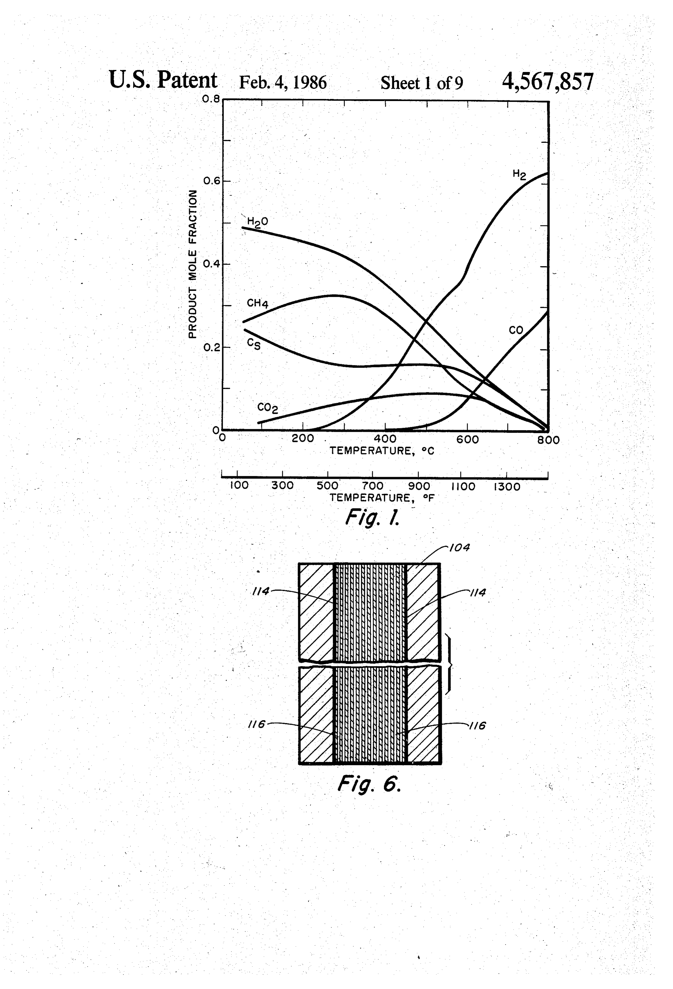
NOY production and increased engine efficiency. One To facilitate this endothermic chemical reaction and of the disadvantages of hydrogen fueled engines is the further enhance the system energy gain, engine exhaust reduction in maximum power as the gaseous fuel dis 25 gas heat can be utilized which usually has a temperature places some of the air during the intake stroke. range from 200° C. to 650 C. Thermodynamic equilib Hydrogen fueled engines have not come into use due rium would predict carbon formation and very little to the difficulty of storing hydrogen onboard a vehicle; hydrogen and carbon monoxide production in the nor either as a compressed gas or as a cryogenic liquid. mal engine exhaust temperature range. This is illus Storage of hydrogen as a hydride appears promising, 30 trated in FIG. 1. Carbon soot not only decreases the but the technology is not sufficiently developed yet and energy efficiency of the methanol decomposition, but the concept has an inherent high weight penalty associ also causes clogging of carburetor jets and float mecha ated with it.
An alternative to hydrogen storage is to generate the nisms.methanol
An example of such a carbon soot producing reactor using exhaust gas as a source of heat is hydrogen onboard the vehicle on demand from a stored given by Dimitroff,
E. and Vitkovits, J.A. of the South liquid fuel. The first choice for such storable liquid fuel is of course gasoline itself. A compact onboard hydro west Research Institute in a paper presented at the 1976 Spring Meeting of the Central States Section of the gen generator has been developed based on the partial Combustion Institute.
oxidation of gasoline with air. (U.S. Pat. No. 4,003,133 issued to Houseman et al.) However, the hydrogen gas A catalyst can be utilized to inhibit the formation of generated from partial oxidation of gasoline contains : carbon and to facilitate the decomposition reaction at undesirable amounts of carbon monoxide, together with lower temperatures by controlling the mechanism by nitrogen diluent. Also, during the conversion of gaso which the methanol molecule reacts. Furthermore, in line to hydrogen 22% of the energy content of the fuel an engine which would be combusting hydrogen/car is released as sensible heat which cannot be utilized. 45 bon monoxide, the engine would probably be operated Also, the hydrogen generator operates at high tempera at leaner equivalence ratios (1,2) which could be as lean tures (980-1050 C), which requires a long start-up as db = 0.5. This would lower the engine exhaust gas time and special materials of construction. temperatures even further demanding the activity of the Gasoline is also undesirable since it is subject to in catalyst to be high and over a wide temperature range creasing fuel costs and to diminishing oil reserves. As a 50 as well as an effective exchange of heat from the exhaust result, there is growing interestin the search for alterna tive fuels to reduce the dependency on expensive oil gasThe into the methanol catalyst bed. imports. Long before today's energy crisis, alcohol fuels tures upcatalyst must be capable of operation attempera were proposed as gasoline-blending compounds for use kPa. A minimum C. to 650 (1200 F), under pressures to 1034 conversion of 80% may be considered in internal combustion (IC) engines. Two alcohol com acceptable under maximum flow
conditions depending pounds, ethanol and methanol, are still receiving contin ued attention. Racing cars, for example, use alcohol on the engine and duty. The catalyst must be able to withstand condensation of liquid methanol on the cata blends because of their increased power relative to lyst particles which may occur during cold start with gasoline.
Ethanol can be produced by fermentation from agri out spoiling or crumbling. High structural integrity. cultural products such as grain, cane, molasses, pota during thermal cycling without carbon formation are toes, and mannite, a tropical plant. Methanol can be also necessary catalyst properties. Selectivity of metha manufactured from a large variety of materials, includ nol decomposition (to hydrogen and carbon monoxide) ing wood, seaweed, municipal wastes, residual oil, peat, over dehydration to dimethyl ether (2CH3OH-Cand coal. Because of the abundant coal reserves in the 65 H3OCH3--H2O) and limited activity for methanation United States, the future supply of methanol seems due to product recombination (3H2--CO-CH4+ H2O) more promising than that of ethanol. Further, methanol under the various operating conditions are also impor can be produced relatively easily from coal gasification tant considerations.
Page 12
SUMMARY OF THE INVENTION homogeneous conditions in the combustion chamber. The well-mixed air/gas mixture will have a lower aver
A methanol decomposition reactor has been provided age temperature (but high enough to sustain methanol in accordance with this invention. The reactor can be decomposition with exhaust gas) after combustion than efficiently and reliably operated at normal exhaust gas Diesel fuel combustion and therefore produce less NO. temperatures in the range of 200 to 650 degrees C. with The smoke from Diesel fuel combustion is also greatly no production of soot. This is accomplished in this in reduced.
vention by the operation of a catalytic reactor under The use of a gaseous fuel reduces the maximum conditions to produce a hydrogen-rich product gas power output of an engine, as the gaseous fuel takes up while eliminating production of solid carbon at the 10 some of the air volume during the intake stroke. This normal temperature range of exhaust gases of internal problem is partially remedied by cooling the gaseous combustion engines. The present invention also pro fuel prior to introduction into the engine. Also, there vides use of mixed fuels for transient power gain and for are occasions where absolute maximum power from an cold start of the engine. engine is demanded, e.g. in passing. To provide this The catalytic methanol dissociation reactor of this 15 capability, some liquid methanol can be made to by-pass invention combines the elements of (1) a configuration the hydrogen generator so that liquid methanol is fed compatible with the system into which it will be incor directly to the engine. Liquid methanol burns quite porated; (2) effective utilization of the exhaust gas heat well, and maximum power can be obtained this way. In by means of proper design to enhance heat transfer into the case of the Diesel engine, the methanol may be the catalyst bed, and (3) a catalyst selection which will 20 injected into the combustion chamber. efficiently and selectively dissociate methanol under all Other features and attendant advantages of the pres operating conditions encountered while simultaneously ent invention will become apparent as the invention maintaining activity and structural integrity. becomes better understood by reference to the follow The methanol reactor has a flow-through decomposi ing detailed description when considered in conjunction tion zone which contains a porous bed of solid, selec 25 with the accompanying drawings.
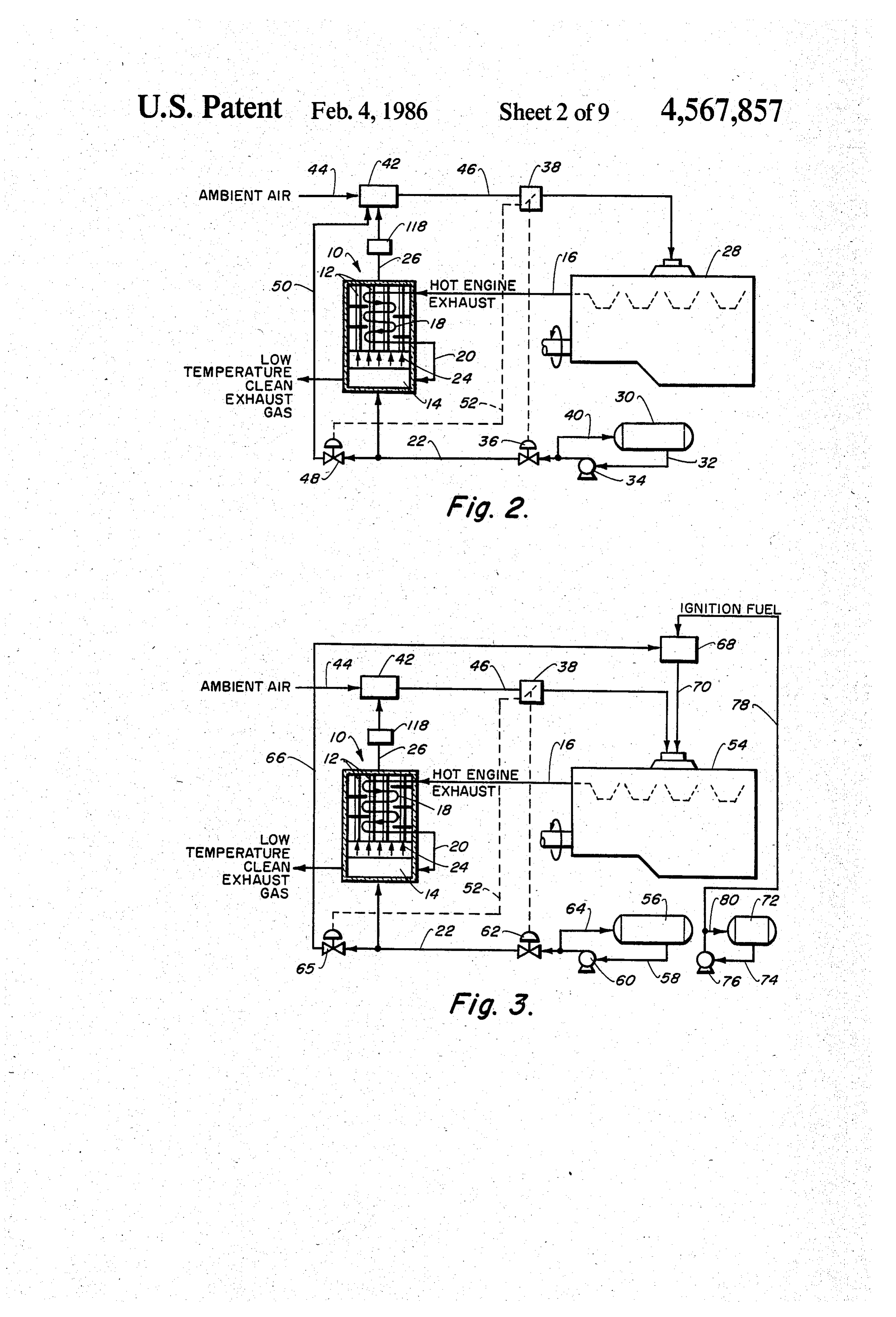
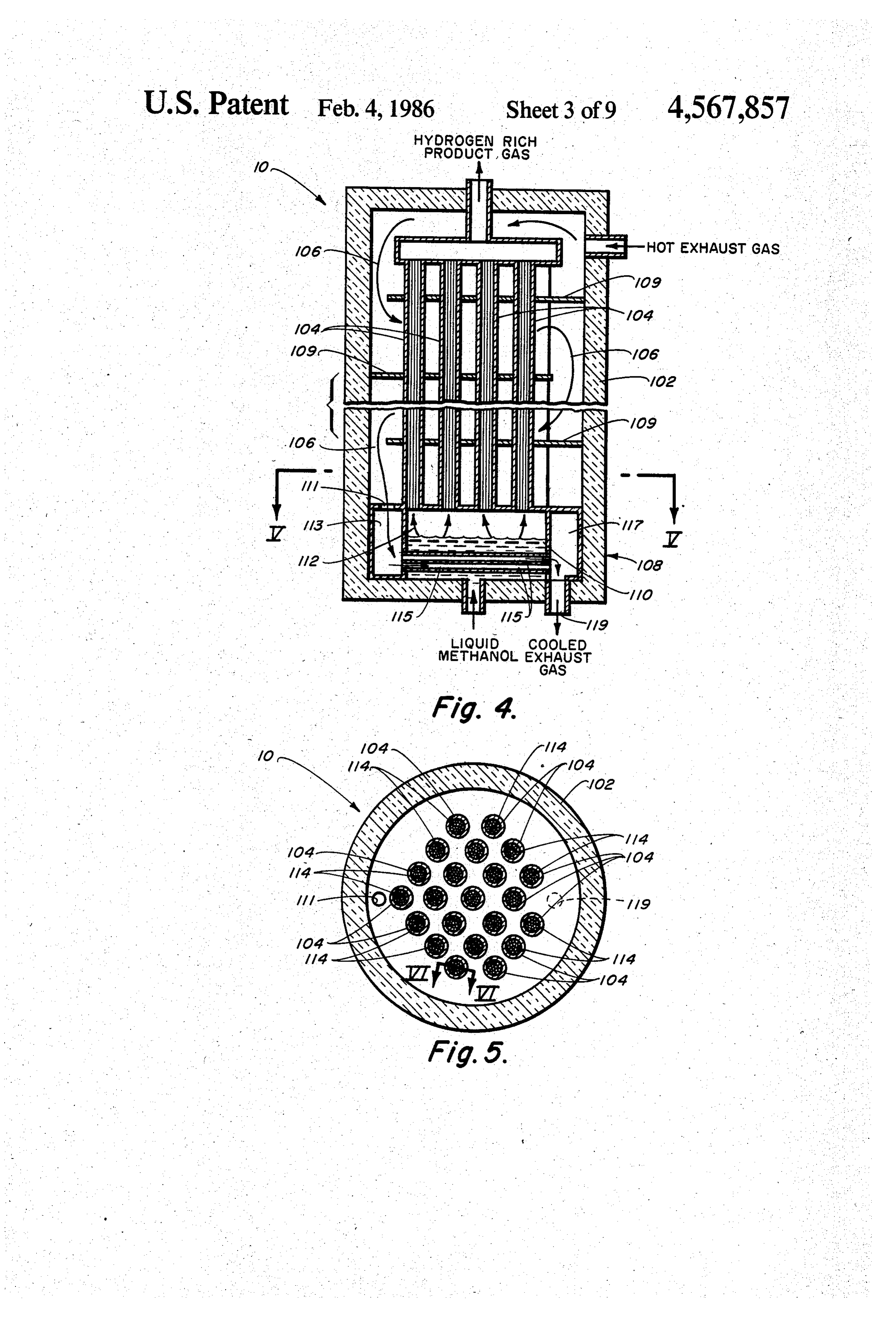
tive, decomposition catalyst and a means of heating this BRIEF DESCRIPTION OF THE DRAWINGS zone, preferably with the exhaust gases. The exhaust gases heat the decomposition zone to temperatures be FIG. 1 is a thermodynamic equilibrium graph show tween 200 and 650 C. which results in the decomposi ing the equilibrium thermal decomposition products of tion of methanol to produce a hydrogen-rich product 30 methanol decomposition at different temperatures. gas. The liquid methanol can be vaporized and super FIG. 2 is a diagrammatic representation of a pre heated in a vaporizer prior to introduction into the ferred engine combustion system utilizing a spark ig decomposition reactor. The vaporizer preferably re nited engine;
* ceives the heat necessary for vaporization of the metha FIG. 3 is a diagrammatic representation of a pre nol by passing the exhaust gases after they leave the 35 ferred engine combustion system utilizing a compres it decomposition reactor into indirect thermal contact sion ignited (Diesel) engine;
with the methanol. Engine cooling water may also be FIG. 4 is a more detailed schematic drawing of a used to vaporize the methanol. preferred catalytic reactor of the present invention; The catalytic methanol reactor may be used in combi FIG. 5 is a cross-sectional view of FIG. 4 taken in the nation with either a spark ignition combustion or com V-V plane;
pression ignition (Diesel) engine to form a combustion engine system.
FIG. 6 is a detailed cross-sectional view of FIG. 5 taken in the VI-VI plane;
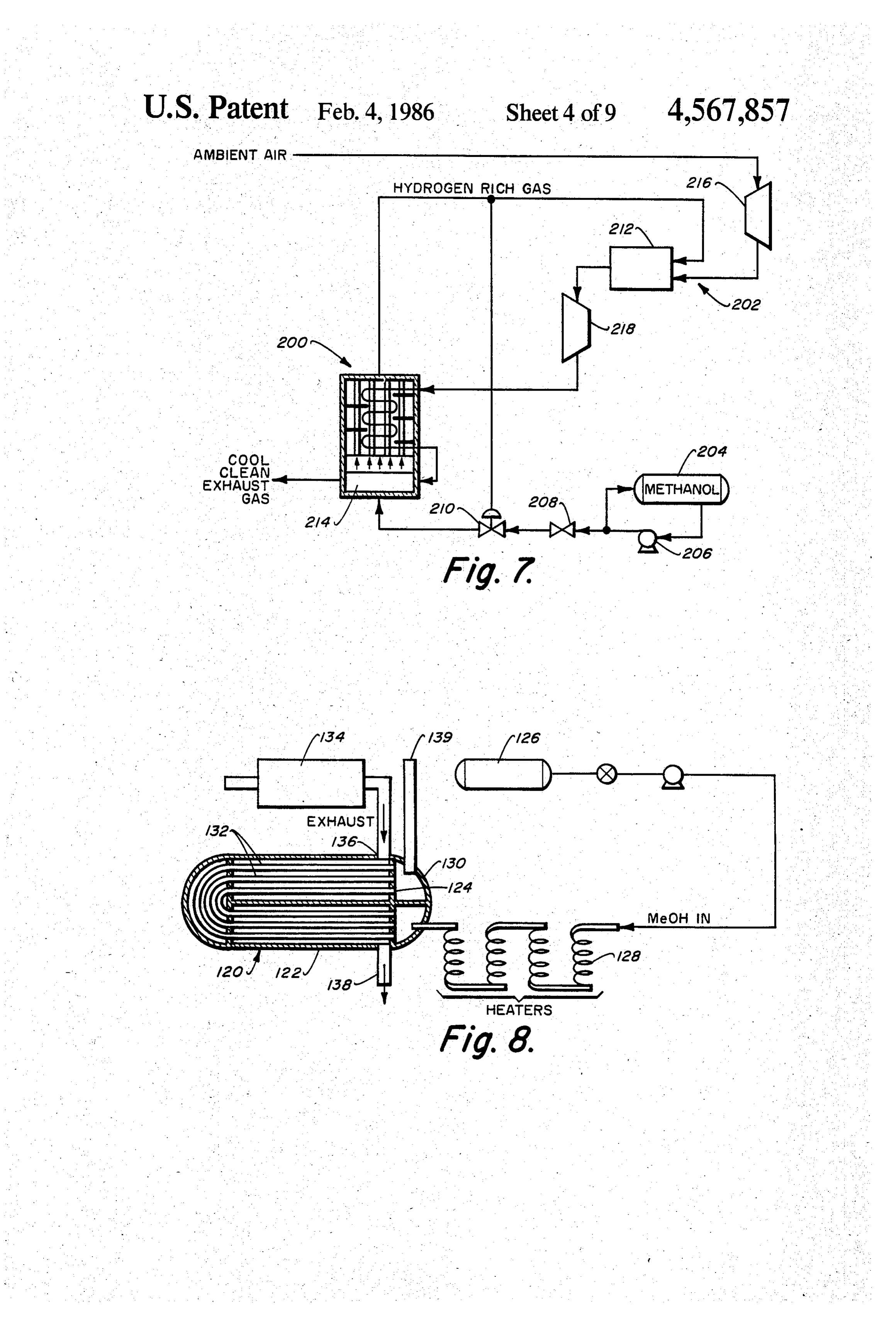
The combustion engine system includes a vaporizer FIG. 7 is a schematic view of a methanol decomposi for vaporizing liquid methanol fuel which is fed to the tion bottoming cycle in combination with a gas turbine; vaporizer from a fuel reservoir. The heated vapors of 45 FIG. 8 is a schematic view of an experimental metha methanol fuel are catalytically decomposed in the reac nol decomposition reactor;
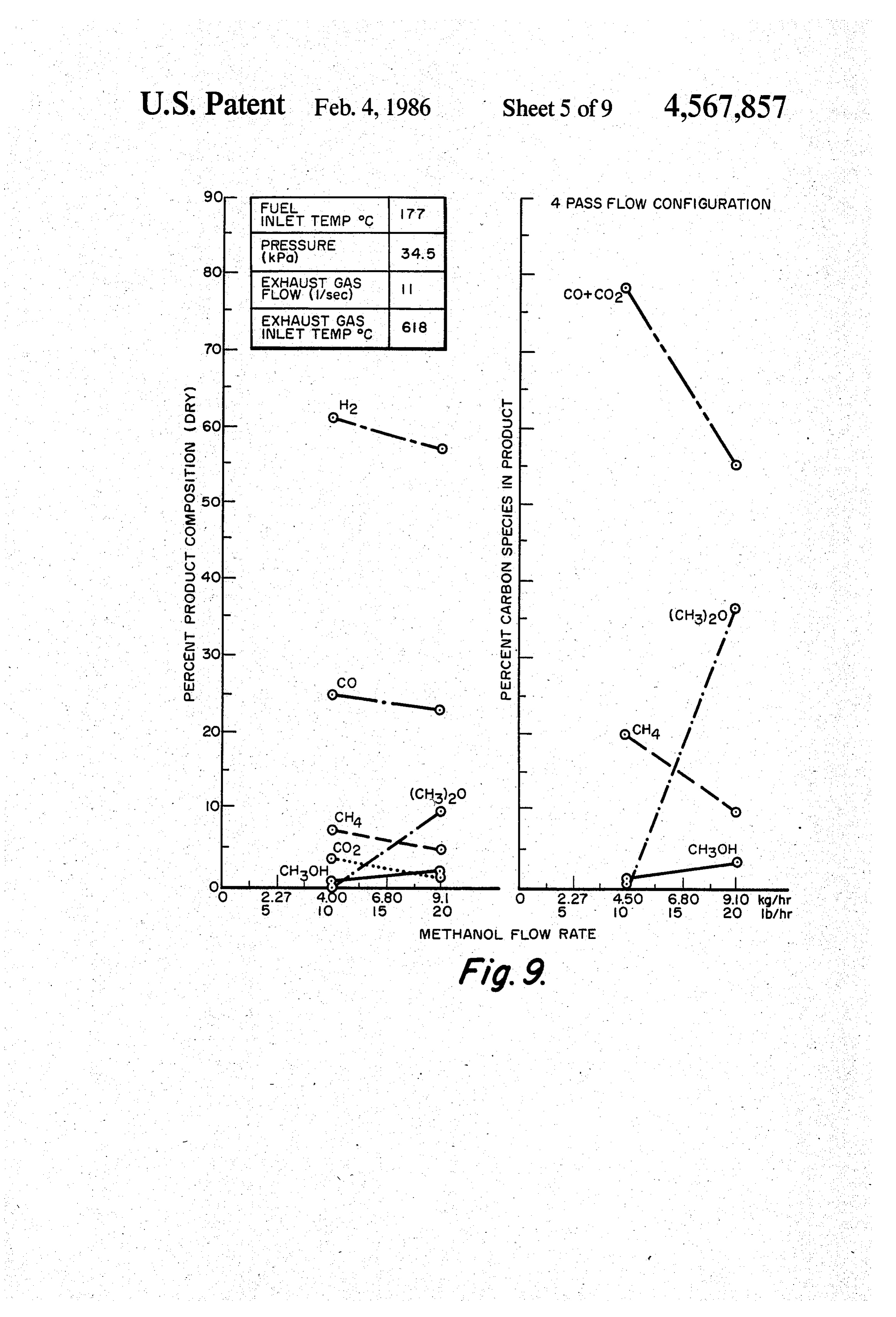
tor and the product gas is transferred to a carburetor FIG. 9 is a set of graphs showing effect of methanol where it is mixed with an oxygen containing gas, such as flow rate on conversion;
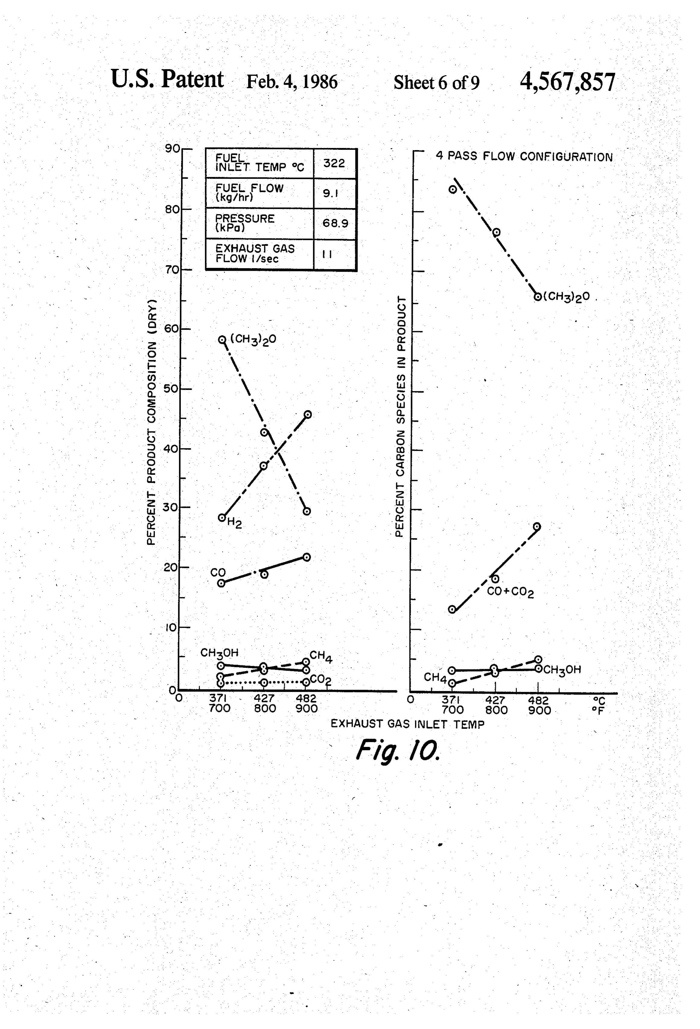
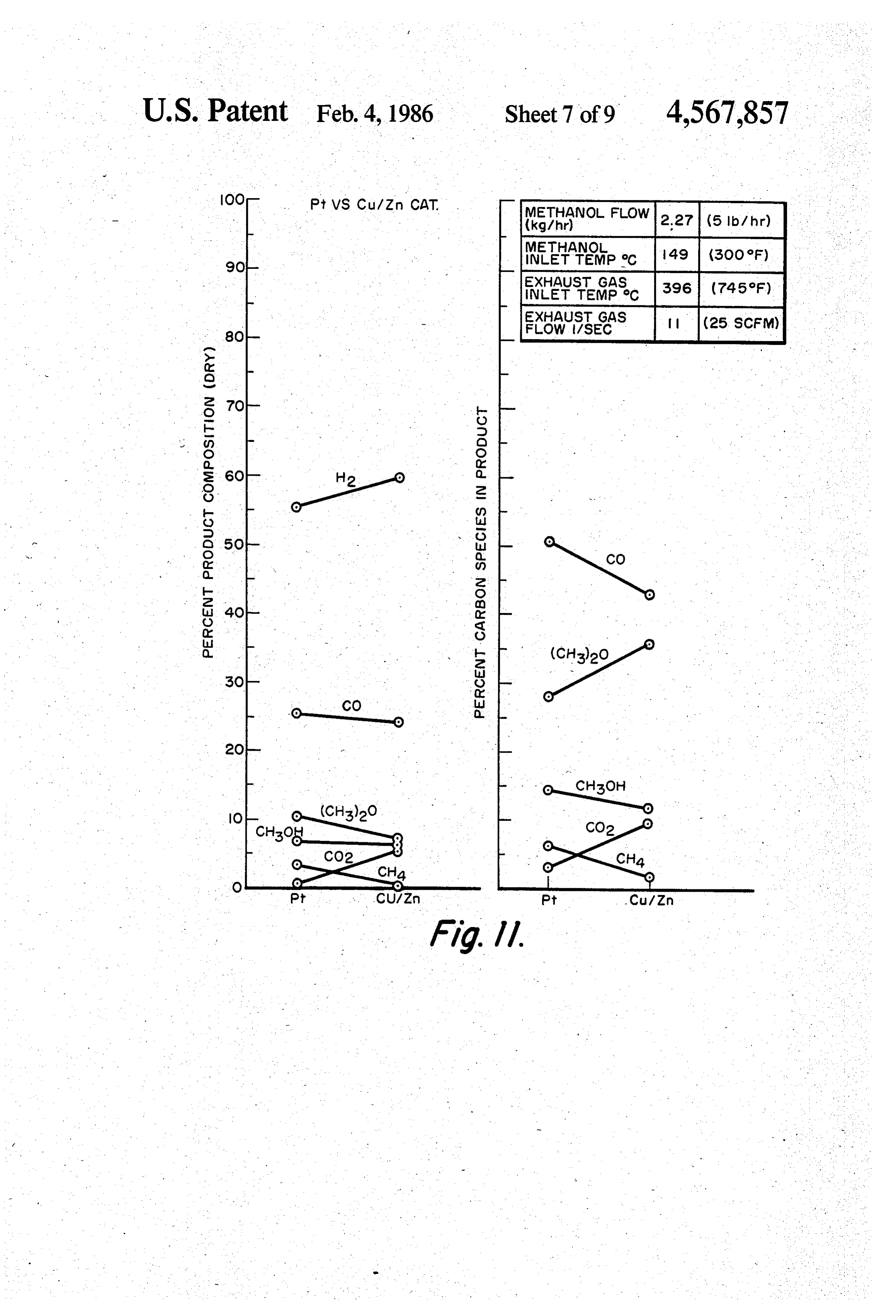
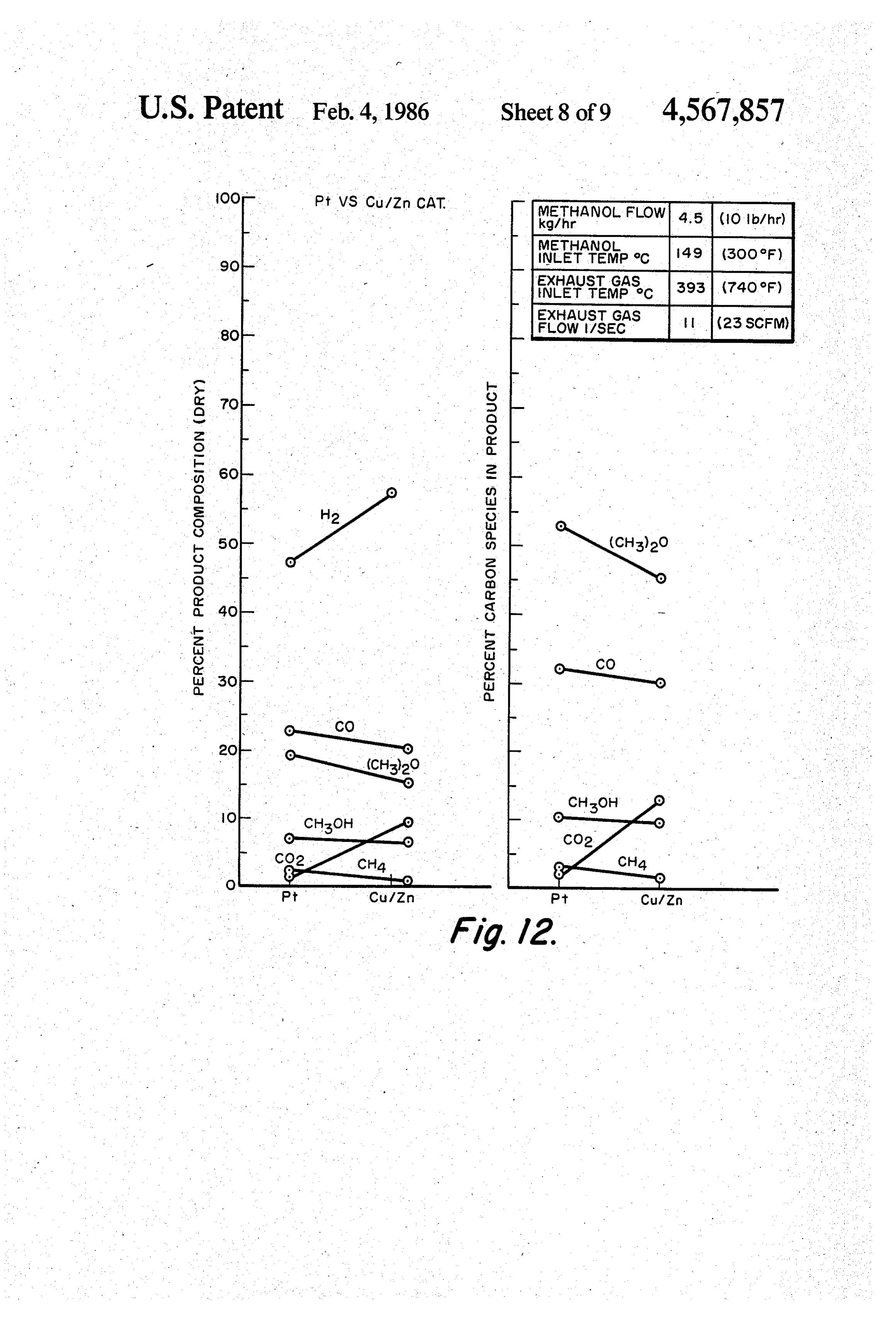
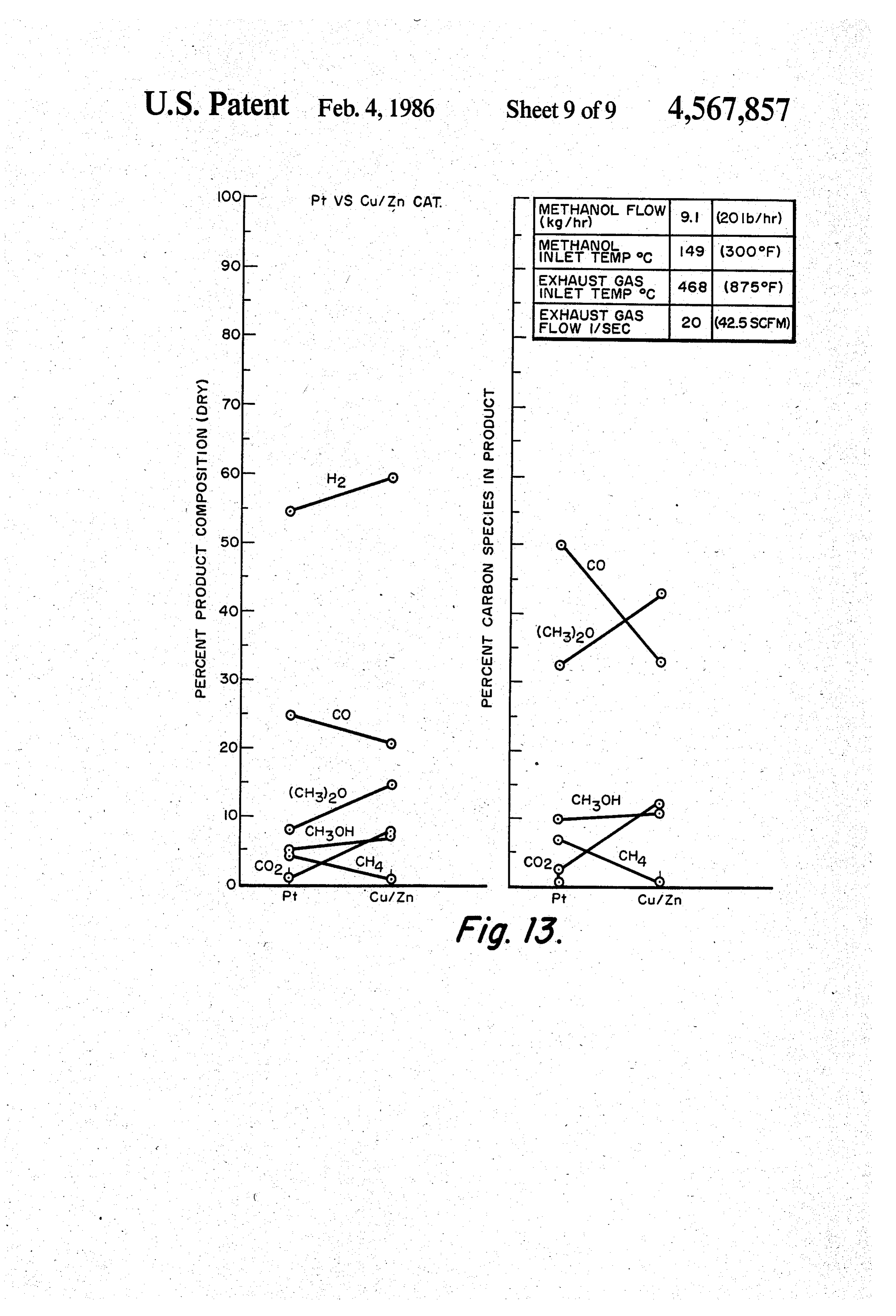
air, to form a combustion gas. The combustion gas is fed FIG. 10 is also a set of graphs showing effect of ex into a combustion reactor where the combustion gas is 50 haust gas inlet temperature on conversion; ignited to produce power, heat and hot exhaust gas. FIG. 11 is a set of graphs showing comparison of Pt The hot exhaust gas produced in the combustion and Cu/Zn catalysts at 5 lb/hour methanol flow; reactor provides means for heating the decomposition FIG. 12 is a set of graphs showing comparison of the zone and is also used by the vaporizer in vaporizing the same catalysts at 10 lb/hour; and methanol fuel and heating the vapors. Since the decom 55 FIG. 13 is a set of graphs showing comparison of position of methanol is an endothermic reaction, the these catalysts at 20 lb/hour.
thermal energy required for this conversion is stored in DETALED DESCRIPTION OF THE the fuel as potential chemical energy in the form of INVENTION hydrogen and carbon monoxide. Therefore, the thermal efficiency of the reactor-engine system is increased by 60 FIG. 1 is a graph which has been included as part of the amount of thermal energy extracted from the ex the detailed description to demonstrate a serious prob haust gases for the vaporization and decomposition of lem which the present invention solves. In viewing methanol. FIG. 1, it can be seen that attemperatures below 200 C. In the case of the compression-ignition (Diesel) en thermal decomposition of methanol can result in the gine, the gas is aspirated into the combustion air, and the 65 production of water, methane, solid carbon and carbon air/gas mixture is uniformly mixed and the combustion dioxide. As the temperature is increased, methanol be conditions are well-defined relative to the normal con gins to thermally decompose into hydrogen and carbon ditions in which a jet of liquid fuel burns under non monoxide. However, below 800° C. there can be signifi
Page 13
cant amounts of water, methane, solid carbon and car tivity material such as a metal wall. The decomposition bon dioxide in the methanol decomposition products. It zone is preferably enclosed by an elongated cylinder of is only above 800 C. that the equilibrium product gas of metal. The hot exhaust gases can be flowed concur thermal methanol decomposition contains only hydro rently or countercurrently past the wall of the zone. gen and carbon monoxide. As previously discussed, it is Countercurrent axial flow is preferred so that the hotter highly desirable to utilize methanol as a storable liquid gases are first utilized to decompose methanol and the fuel which is decomposed to produce a hydrogen-rich cooler gases still retain sufficient thermal value to va product gas for use in a hydrogen-fueled engine. How porize and superheat the methanol liquid. ever, as shown in FIG. 1, for simple thermal decomposi The body of catalyst can be particulate, or a mono tion of methanol to be effective at thermodynamic equi 10 lithic, integral porous mass. Though a bed of particulate librium conditions, it must be carried out at over 800' C. catalyst can be utilized, the particles tend to self-abrade Since normal internal combustion engine exhaust gases from the vibrational forces experienced in an internal vary in temperature from 400' to 700° C., there is a combustion engine vehicle and form fines which clog severe problem presented in providing the amount of the bed. Furthermore, any fines that are carried over heat necessary to thermally decompose methanol into a 15 into the engine can seriously damage the latter so pre soot-free hydrogen gas. w cautions would have to be implemented such as a filter The present invention utilizes selective catalysts to to prohibit this. In addition, catalyst particles are only in produce a product gas containing only hydrogen and point contact providing very poor heat transfer charac carbon monoxide at the lower exhaust gas temperatures teristics.
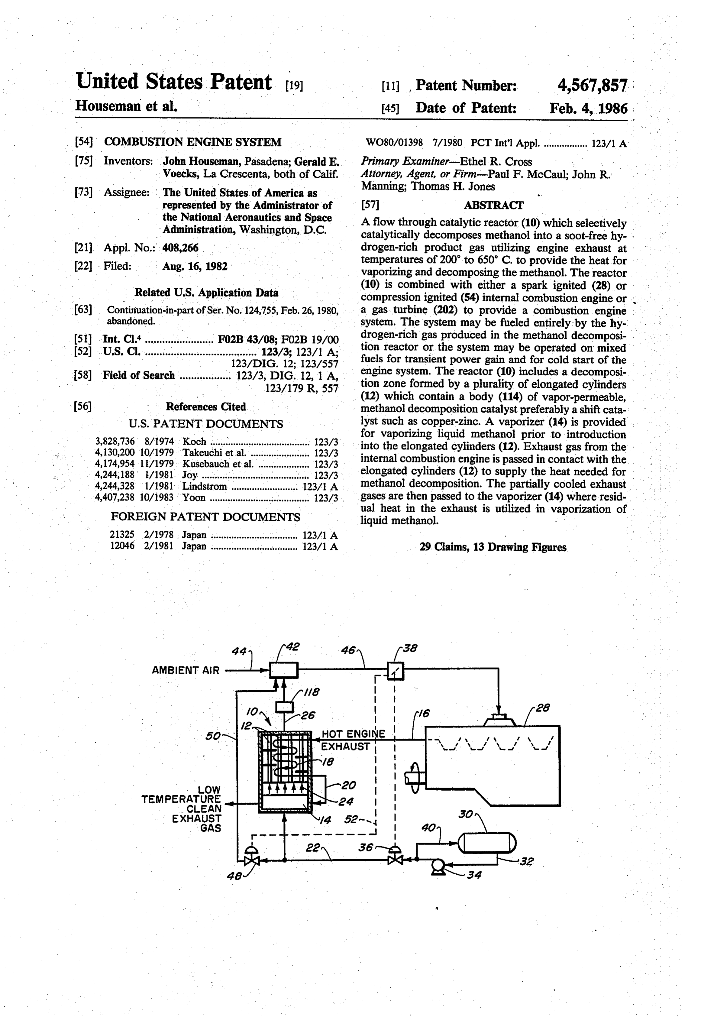
of 200 to 650 C. The catalytic reactor of the present 20 Therefore, it is preferred that the catalyst be fabri invention is shown in both FIGS. 2 and 3. In FIG. 2 the cated in monolithic form. The preferred form of reactor catalytic reactor is used in combination with a spark is a series of elongated axial tubes containing an insert of ignited combustion engine and in FIG. 3 the catalytic permeable monolithic form. The preferred form of reac reactor is used incombination with a compression igni tor is a series of elongated axial tubes containing an tion (Diesel) engine. The catalytic reactor in both 25 insert of permeable monolithic catalyst. The outside FIGS. 2 and 3 are identical and the same numbers will surface of the tubes provides a large surface area for be used for their identification. heat transfer and the monolithic element provides excel . . . The catalytic reactor of the present invention is lent heat absorption and a large surface area for cata shown generally at 10 in FIGS. 2 and 3. The catalytic. lytic decomposition. The monolithic catalyst insert can reactor 10 is divided into a flow-through decomposition 30 be in the form of an irregular mesh or sponge-like body zone defined by elongated tubes 12 and a vaporizer 14. . or a solid, cylindrical insert element containing a plural The elongated tubes 12 contain the vapor-permeable ity of elongated, continuous, parallel passages. The . . decomposition catalyst in various types and forms insert can be formed of high heat conductivity ceramic a which will be described in detail later. The elongated or metal containing a coating of catalyst on the surface tubes 12 are heated by hot engine exhaust gases intro 35 of the passages. The catalyst may be bound via a higher duced into the catalytic reactor via exhaust conduit 16. surface area material, a so called washcoat, according to The hot engine exhaust gases flow past the outer sur methods commonly used in catalyst preparation and *faces of the bank of elongated tubes 12 as indicated by well-known to those well-versed in the state-of-the-art. line 18. As the hot engine exhaust gases travel from the Another option for catalyst retention with the tubes. top of the elongated tubes 12 to the bottom as indicated 40 12 is to bind the catalyst to the inside tube wall. This by the arrows along line 18, heat transfer occurs and the provides efficient heat transfer to the catalyst. Catalysts exhaust gases become partially cooled. The exhaust fixed in this manner are commonly used in industry. gases are then passed via conduit 20 to the vaporizer 14 The preferred catalysts for efficiently and selectively where residual heat remaining in the exhaust gas is used decomposing methanol to hydrogen and carbon monox to vaporize liquid fuel entering the vaporizer 14. Al 45 ide are methanol-reforming catalysts such as copper though the present invention is not necessarily limited zinc, copper-chromium or zinc-chromium or noble met to methanol as a fuel, methanol fuel is preferred. als such as platinum or palladium. The binary catalysts In operation, methanol is introduced into the vapor such as copper-zinc can be present as separate compo izer 14 via feedline 22. The vaporizer 14 vaporizes the nents, an alloy and can contain other ingredients such as methanol fuel to form a precursor gas which is intro SO rare earth promoters. The noble metal catalysts can also duced as indicated by arrows 24 into the elongated contain promoters to permit reaction at lower tempera tubes 12. The precursor gas flows upwardly through tures while avoiding soot formation at higher tempera the elongated tubes containing methanol decomposition tures. The catalysts can be provided in pure form or can catalyst where it is heated in contact with the catalyst be coated on the surface of a solid support such as alu and thereby decomposed to a soot-free hydrogen-rich 55 mina pellets in an amount from 0.1 to 20% by weight of fuel which is removed from the catalytic reactor by the pellets, usually from 0.5 to 5%. The catalysts can be product removal conduit 26. The particular operating coated onto the surface of the passages through the parameters within the catalytic reactor 10 such as tem monolithic elements and may be bound through the use perature, precursor gas residence time, flow rate and of a slipcoat material such as is commonly used in vehic methanol decomposition catalyst, may be varied to ular auto exhaust gas clean-up catalysts. achieve the production of a soot-free hydrogen and Referring now to FIGS. 4, 5 and 6, FIG. 4 is a more carbon monoxide product gas. detailed schematic representation of the catalytic reac The catalyst is disposed in the flow-through decom tor 10 shown in FIGS. 2 and 3. The reactor 10 has position zone as a gas-permeable solid body. The solid insulated walls 102 to minimize radiant heat loss. Hot body of catalyst also operates as a heat sink for the 65 exhaust gas from an internal combustion engine is intro thermal energy absorbed by conduction from the ex duced into the reactor 10 as shown. The heat from the haust gases. The decomposition zone is isolated from hot gas is transferred to elongated metal cylinders 104 the flow of exhaust gases by a wall of high heat conduc which in turn transfer the heat to the catalyst and meth
Page 14
anol gas therein. Baffles 109 are provided for circulating a bypass capability where liquid fuel may be fed to the the exhaust gases evenly around the metal cylinders carburetor rather than or in addition to the gaseous 104. The partially cooled exhaust gases are passed (as product fuel. To provide for this capability, valve 48 is shown by curving arrows 106) around the metal cylin provided which when open allows methanol to be fed ders and into vaporizer 108 through port 111 into directly through line 50 into line 26 and subsequently header 113 and passed through heat exchange tubes 115 carburetor 42. The bypass valve 48 is actuated by the and collected in outlet header 117 and are exhausted throttle when full throttle is applied as shown by dotted through outlet 119. The remaining heat in the partially line 52. The above-described technique can also be used cooled exhaust gases is absorbed by the vaporizer 108 to to start the engine from rest when the catalytic reactor vaporize the methanol liquid 110 into methanol vapor, 10 10 has not yet reached operating temperatures for meth as shown by arrows 112, which flow into the catalyst anol decomposition.
containing metal cylinders 104. If sufficient heat is pres Another method for starting the engine not involving ent in the partially cooled exhaust gas, the methanol the use of liquid methanol involves a steady state accu may also be superheated above vaporization tempera mulator (not shown). The steady state accumulator may tures in the vaporizer 108. 15 be used to accumulate decomposed product gases dur FIG. 5 is a cross section of the reactor showing an ing steady state operation of the vehicle when the de end view of the metal cylinders 104. The preferred composed gases generated are in excess of engine de monolithic catalyst insert is shown at 114. FIG. 6 is a mand. These surplus gases may be accumulated and detailed elongated sectional view of the preferred stored in the steady state accumulator and later used monolithic catalyst insert showing the plurality of elon 20 during engine start-up, thus eliminating any cold-start gated continuous parallel passageways 116. ing problems which may be associated with the use of Operation of the hydrogen generator with as short a straight liquid methanol. Clearly, the use of a steady residence time as possible with the highest practical state accumulator would require considerable control space velocity will favor soot-free hydrogen/carbon equipment and also occupies sizable space; hence, its use monoxide formation at the 200 to 650 C. temperature 25 may not be practical where space limitations must be of typical exhaust gases. considered.
Referring to FIG. 2, the catalytic reactor 10 is shown For a given system, the amount of methanol that can in combination with a spark-ignited internal combustion be decomposed depends on the temperature and amount engine 28. Liquid methanol for use in the combustion of the exhaust gases. This, in turn, depends on the re system is stored in reservoir 30. The liquid methanol is 30 quired power level and the equivalence ratio that is fed through line 32 to fuel pump 34 which supplies the used. For an equivalence ratio of unity, the exhaust gas necessary pressure for pumping the liquid fuel into the must be cooled by 480 C. in order to provide the re vaporizer 14. Fuel valve 36 is provided for controlling quired heat for complete decomposition of the metha the flow of liquid methanol to vaporizer 14. The fuel nol. At lower equivalence ratios, the temperature drop valve 36 is operated between open and idle positions by 35 required is less. Exhaust temperatures upstream of the throttle 38. As the throttle 38 is moved from the idle to hydrogen generator range from 260' to 650 C., de full power position, valve 36 is correspondingly moved pending upon the equivalence ratio. A simple energy from a relatively closed (idle) position to a position balance shows that this range of exhaust temperatures is allowing increased flow of methanol liquid. Provision is high enough for complete methanol decomposition. made via line 40 to recycle excess methanol liquid back After the decomposition cycle has started, the upstream to the methanol reservoir 30. exhaust temperatures will be maintained for a given As previously described, the liquid methanol is equivalence ratio to be adequate for catalytic decompo passed via feed line 22 into the catalytic reactor 10 sition of the methanol.
where the methanol is thermo-catalytically decom FIG. 3 shows the catalytic reactor 10 in combination posed to hydrogen and carbon monoxide to form a 45 with a compression-ignited (Diesel) internal combus product gas which is removed via line 26. The product tion engine 54. Operation of the Diesel combustion gas in line 26 is introduced into carburetor 42. The system is very similar to the operation of a spark-ignited carburetor 42 mixes the product gas from line 26 with combustion system except for minor differences regard air introduced through line 44 to produce a combustion ing injection of liquid methanol and Diesel fuel into the gas. The combustion gas is then transferred to the inter 50 Diesel engine 54. As was the case for the spark-ignited nal combustion engine 28 via carburetor line 46. The combustion engine system, the Diesel combustion sys control of combustion gas flow to the internal combus tem includes a liquid methanol reservoir 56 having a tion engine 28 is also controlled by throttle 38. The feed line 58 for transferring the liquid methanol to a fuel combustion gas, upon entering the internal combustion pump 60. Throttle-actuated fuel valve 62 is also pro engine 28 is spark-ignited to produce power, hot engine 55 vided for controlling the amount of methanol trans exhaust and a certain amount of waste heat. Approxi ferred through line 22 into the catalytic reactor 10. mately a third of the energy generated during the com Liquid recycle line 64 is provided for returning metha bustion of the combustion gas is present in the hot en nol fuel to the methanol reservoir 56 as excess fuel is gine exhaust. The hot engine exhaust is cycled via line being pumped by fuel pump 60. Bypass valve 65 is pro 16 to the reactor 10 for heating the elongated tubes 12 60 vided for allowing methanol fuel to bypass the catalytic and the vaporizer 14. reactor during maximum power output. The methanol One of the few disadvantages of a gaseous fuel rela fuel flows from bypass valve 65 through line 66 to injec tive to a liquid fuel is that for a given equivalence ratio tor 68. The injector injects the methanol fuel into the (actual fuel-to-air ratio divided by stoichiometric fuel Diesel engine 54 via line 70. As can be seen in the Diesel to-air ratio), maximum engine power is reduced, since 65 combustion system, the methanol liquid fuel which the gaseous fuel displaces some of the air during the bypasses the catalytic reactor 10 is not mixed with air in intake stroke. Since there are occasions when absolute the carburetor 42 but is injected directly into the Diesel maximum power is demanded, it is desirable to provide engine 54 as is common in Diesel engine operation.
Page 15
It should be noted that in conventional Diesel en The resulting hydrogen-rich gas is thenburned in the gines, ignition is initiated by the heat of compression. combustor 200 with compressed air from air compres However, unlike Diesel fuel, hydrogen-rich product sor 216. The hot combustion gases from the combustor gases do not ignite very well by compression heat alone. 202 then pass through the expander 218, thus producing This requires a small pilotjet of liquid fuel to be injected mechanical work, and then pass through the catalytic into the Diesel engine 54 to initiate the ignition. Once reactor 200 and the methanol vaporizer 214. the flame has started, it will propagate throughout the Additional advantages in this type of combustion combustible gas mixture. Although methanol may be system versus a direct liquid methanol system are lower used as the pilot charge, some problems have been expe possible equivalence ratios in the combustor, as a result rienced with its use as such. Therefore, provision has 10 of the high flame speed of hydrogen, accompanied by been made for injecting a small pilot charge (about lower combustion temperatures, producing lower NOx equal to the idling charge of the engine) of Diesel fuel and requiring less combustor maintenance. into the Diesel engine 54. Specifically, Diesel fuel reser Experimental voir 72 is provided for supplying Diesel fuel through line 74 to Diesel fuel pump 76. The Diesel fuel pump A stainless steel reactor 120 having a basic shell 122 pumps the Diesel fuel under pressure through line 78 to and tube 124 design was constructed in FIG. 8. Liquid injector 68 which injects the desired pilot charge of . methanol from storage tank 126 was vaporized in coil Diesel fuel through line 70 into the Diesel engine 54. heater 128 and the vapors fed to the inlet head 130 of the Recycle line 80 is provided for recycling Diesel fuel 20 tubes 124. The tubes contained a porous body 132 of back to the reservoir 72 as excess amounts of Diesel fuel particulate decomposition catalyst. Reformed gas was are being pumped by pump 76. The same system can be recovered through outlet 139. Exhaust gas generated in utilized to start and idle the engine. furnace 134 flowed into the shell 122 through inlet 136 The high temperatures of decomposed methanol can past the tubes 124 and was removed through outlet 138. : reduce charge density at the engine inlet and, hence, 25 0.953 A reactor was constructed with seventy-U-tubes of power. Fortunately, these losses can be controlled to cm (0.375 in.)0.D. stainless steel tubing. The stain less shell diameter was 18.7 cm (7.38 in.), with a wall some extent by employing a forecooler, as shown 118 in thickness
FIGS. 2 and 3. of 0.159 cm (0.0625 in.) and the overall length Product gases leave the hydrogen generator at 250 Seven of the shell-and-tube section was 94.7 cm (37.3 in.). C. If these gases are not cooled in a forecooler, the 30 spacedpairs of baffles (not shown) were located evenly engine inlet charge temperatures will be high because of haust gasalong the tubes for directing the two-pass ex the high specific heat of hydrogen. In the absence of bolted directly across flow the tubes. The bell, or head, was onto the shell flange and retained a gas forecooler 118, average temperatures of the decom keted screen which sealed the unit as well as held the posed methanol-air mixture will be over 50 C. This catalyst in place in the tubes. The head was designed to high temperature reduces the inlet charge density and, 35 hence, engine power. These losses are reduced by cool provide tube either a two-pass or four-pass configuration for flow. Taps in the bottom half of the head were used sing the decomposed gases in forecooler 118. to monitor mid-point product and temperature during Although the power losses resulting from high . four-pass operation.
charge temperatures of decomposed methanol can be line leaving the portProduct gas was sampled from the reduced by employing forecooler 118, it is not possible 40 couples were located in the catalystquadrant. onthe product bed at
Thermo the tube to prevent volumetric power losses. Decomposed meth- . ends, at the inlet and exhaust ports of both engine ex anol reduces maximum engine power, since the gaseous haust and methanol feedstream, in contact with tube . . fuel displaces some air during the intake stroke. How walls in two locations on each exhaust pass and in the ever, increased heating value of decomposed methanol mid-point exhaust gas stream. The total unit, with cata and increased engine efficiency at low equivalence ra- 45 tios largely compensate for the losses in power resulting lyst, weighed 56.7 kg (125 lbs). Gas analysis was accomplished by passing some of from using a gaseous fuel. the product or mid-point gas stream through a series of FIG. 7 shows the catalytic reactor 200 in combina on line analyzers and a gas chromatograph.
tion with a gas turbine 202. Gas turbines are routinely A stainless steel column packed with Poropak Q was run on natural gas, which in this case is replaced by the 50 used for hydrocarbon separation on the gas chromato hydrogen-rich gas product from the catalytic reactor. graph.
The catalytic reactor in this case is operated at elevated Methanol was fed under pressure through a rotome pressure (say 150 psig), as the combustor is operated at terto a series of heated copper tubing coils. No dissocia close to this pressure level. tion was found to take place when methanol was heated As in the previous system, a methanol tank 204 deliv-55 to the maximum inlet temperature of 316' C. (600°F) in ers the methanol by means of a fuel pump 206 to the this heater system.
catalytic reactor 200 (or hydrogen generator), this time Heated exhaust gas to the reactor was supplied by a at elevated pressure in excess of 150 psig. A bypass separate V-8 engine. Gaseous flow was monitored by a valve 210 allows injection of liquid methanol directly Meriam laminar airflow meter. The exhaust gas flowed into the gas turbine combustor 212 for start up. 60 through an electric tube furnace just prior to reactor Once the hot turbine exhaust gases have heated up entry which enabled fine tune control on the tempera the catalytic reactor 200, the bypass valve 210 directs ture of the exhaust gas entering the reactor. the liquid methanol towards the methanol vaporizer Data section 214 in the bottom of the reactor (not shown) and the vaporized methanol passes through the tubes con- 65 All data points were taken after the system had taining the catalyst, thus affecting decomposition. The reached steady state operation at a set condition. Stabil hot turbine exhaust gases provide the required heat by ity was maintained for 10 to 15 minutes before tempera heat transfer through the tube walls. tures and gas compositions were measured.
Page 16
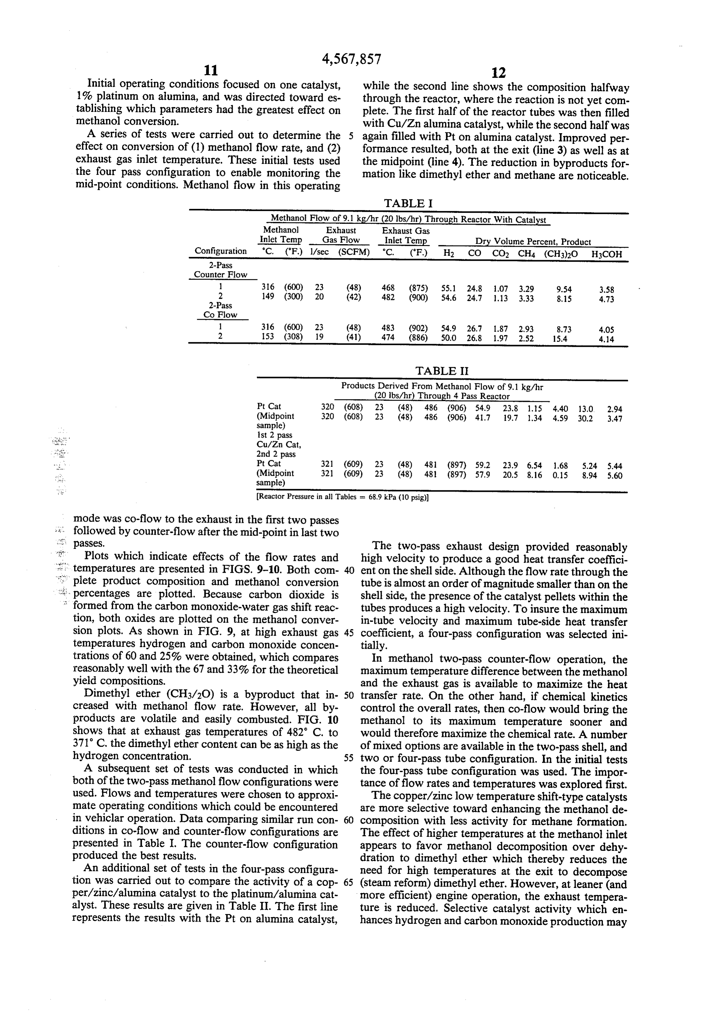
Initial operating conditions focused on one catalyst, while the second line shows the composition halfway 1% platinum on alumina, and was directed toward es through the reactor, where the reaction is not yet com tablishing which parameters had the greatest effect on plete. The first half of the reactor tubes was then filled methanol conversion. with Cu/Zn alumina catalyst, while the second half was A series of tests were carried out to determine the 5 again filled with Pt on alumina catalyst. Improved per effect on conversion of (1) methanol flow rate, and (2) formance resulted, both at the exit (line 3) as well as at exhaust gas inlet temperature. These initial tests used the midpoint (line 4). The reduction in byproducts for the four pass configuration to enable monitoring the mation like dimethyl ether and methane are noticeable. mid-point conditions. Methanol flow in this operating
TABLE I
Methanol Flow of 9.1 kg/hr (20 lbs/hr) Through Reactor With Catalyst
Methanol Exhaust Exhaust Gas
Inlet Temp - Gas Flow Inlet Temp Dry Volume Percent, Product Configuration "C. ("F) l/sec (SCFM) "C. (F) H2 CO CO2 CH4 (CH3)2O H3COH
Counter Flow l 316 (600) 23 (48) 468 (875) 55.1 24.8 1.07 3.29 9.54 3,58 2 149 (300) 20 (42) 482 (900) 54.6 24.7 1.13 3.33 8.15 4.73
Co Flow 1 316 (600) 23 (48) 483 (902) 54.9 26.7 1.87 2.93 8.73 40S 2 153 (308) 19 (41) 474 (886) 50.0 26.8 1.97 2.52 15.4 4.14
TABLE II
Products Derived From Methanol Flow of 9.1 kg/hr (20 lbs/hr) Through 4 Pass Reactor
Pt Cat 320 (608) 23 (48) 486 (906) 54.9 23.8 1.15 4.40 13.0 2.94 (Midpoint 320 (608) 23 (48) 486 (906) 41.7 19.7 l.34 4.59 30.2 3.47 sample) 1st 2 pass
Cu/Zn Cat, 2nd 2 pass
Pt Cat 321 (609) 23 (48) 481 (897) 59.2 23.9 6.54 1.68 5.24 5.44 (Midpoint 321 (609) 23 (48) 481 (897) 57.9 20.5 8.16 0.15 8.94 5,60 sample)
Reactor Pressure in all Tables = 68.9 kPa (10 psig))
mode was co-flow to the exhaust in the first two passes s' passes.
followed by counter-flow after the mid-point in last two
The two-pass exhaust design provided reasonably
Plots which indicate effects of the flow rates and high velocity to produce a good heat transfer coeffici temperatures are presented in FIGS. 9-10. Both com ent on the shell side. Although the flow rate through the plete product composition and methanol conversion tube is almost an order of magnitude smaller than on the percentages are plotted. Because carbon dioxide is shell side, the presence of the catalyst pellets within the formed from the carbon monoxide-water gas shift reac tubes produces a high velocity. To insure the maximum tion, both oxides are plotted on the methanol conver in-tube velocity and maximum tube-side heat transfer sion plots. As shown in FIG. 9, at high exhaust gas 45 coefficient, a four-pass configuration was selected ini temperatures hydrogen and carbon monoxide concen tially.
trations of 60 and 25% were obtained, which compares In methanol two-pass counter-flow operation, the reasonably well with the 67 and 33% for the theoretical maximum temperature difference between the methanol yield compositions. and the exhaust gas is available to maximize the heat Dimethyl ether (CH3/20) is a byproduct that in 50 transfer rate. On the other hand, if chemical kinetics creased with methanol flow rate. However, all by control the overall rates, then co-flow would bring the products are volatile and easily combusted. FIG. 10 methanol to its maximum temperature sooner and shows that at exhaust gas temperatures of 482 C. to would therefore maximize the chemical rate. A number 371 C, the dimethyl ether content can be as high as the of mixed options are available in the two-pass shell, and hydrogen concentration. 55 two or four-pass tube configuration. In the initial tests A subsequent set of tests was conducted in which the four-pass tube configuration was used. The impor both of the two-pass methanol flow configurations were tance of flow rates and temperatures was explored first. used. Flows and temperatures were chosen to approxi The copper/zinc low temperature shift-type catalysts mate operating conditions which could be encountered are more selective toward enhancing the methanol de in vehiclar operation. Data comparing similar run con 60 composition with less activity for methane formation. ditions in co-flow and counter-flow configurations are The effect of higher temperatures at the methanol inlet presented in Table I. The counter-flow configuration appears to favor methanol decomposition over dehy produced the best results. dration to dimethyl ether which thereby reduces the An additional set of tests in the four-pass configura need for high temperatures at the exit to decompose tion was carried out to compare the activity of a cop 65 (steam reform) dimethyl ether. However, at leaner (and per/zinc./alumina catalyst to the platinum/alumina cat more efficient) engine operation, the exhaust tempera alyst. These results are given in Table II. The first line ture is reduced. Selective catalyst activity which en represents the results with the Pt on alumina catalyst, hances hydrogen and carbon monoxide production may
Page 17
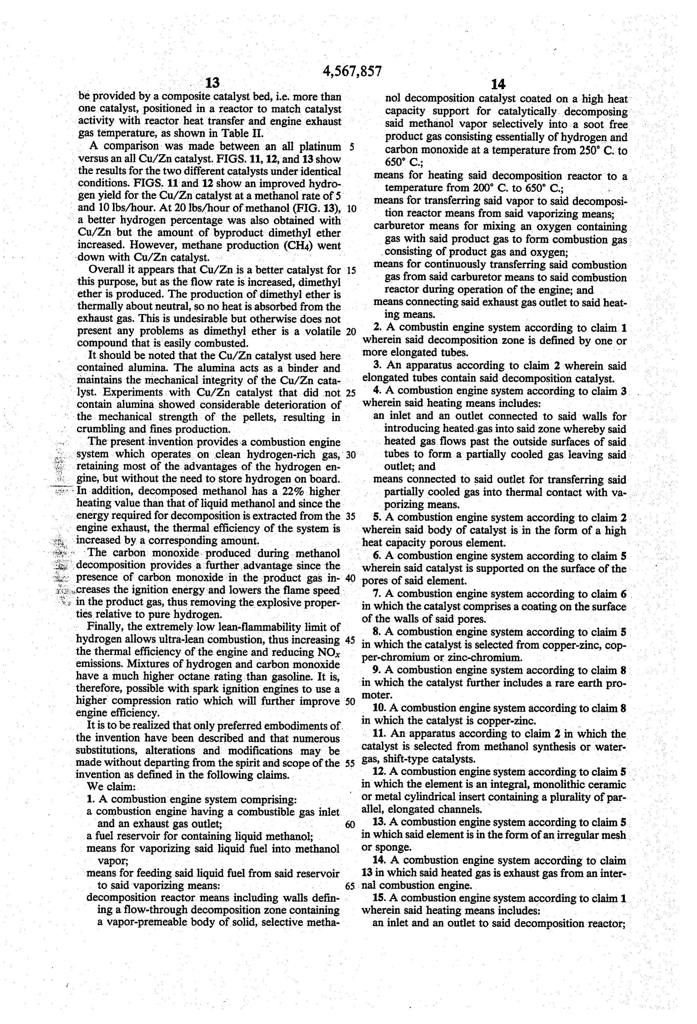
be provided by a composite catalyst bed, i.e. more than nol decomposition catalyst coated on a high heat one catalyst, positioned in a reactor to match catalyst capacity support for catalytically decomposing activity with reactor heat transfer and engine exhaust said methanol vapor selectively into a soot free gas temperature, as shown in Table II. product gas consisting essentially of hydrogen and A comparison was made between an all platinum carbon monoxide at a temperature from 250' C. to versus an all Cu/Zn catalyst. FIGS. 11, 12, and 13 show 650° C.;
the results for the two different catalysts under identical means for heating said decomposition reactor to a conditions. FIGS. 11 and 12 show an improved hydro temperature from 200° C. to 650 C.; w gen yield for the Cu/Zn catalyst at a methanol rate of 5 means for transferring said vapor to said decomposi and 10 lbs/hour. At 20 lbs/hour of methanol (FIG. 13), 10 tion reactor means from said vaporizing means; a better hydrogen percentage was also obtained with carburetor means for mixing an oxygen containing Cu/Zn but the amount of byproduct dimethyl ether gas with said product gas to form combustion gas increased. However, methane production (CH4) went consisting of product gas and oxygen; down with Cu/Zn catalyst. means for continuously transferring said combustion Overall it appears that Cu/Zn is a better catalyst for 15 gas from said carburetor means to said combustion this purpose, but as the flow rate is increased, dimethyl reactor during operation of the engine; and ether is produced. The production of dimethyl ether is thermally about neutral, so no heat is absorbed from the means connecting said exhaust gas outlet to said heat exhaust gas. This is undesirable but otherwise does not ing means.
present any problems as dimethyl ether is a volatile 20 2. A combustin engine system according to claim 1 compound that is easily combusted. wherein said decomposition zone is defined by one or It should be noted that the Cu/Zn catalyst used here more elongated tubes.
contained alumina. The alumina acts as a binder and elongated 3. An apparatus according to claim 2 wherein said maintains the mechanical integrity of the Cu/Zn cata 25 4. A combustion tubes contain said decomposition catalyst. lyst. Experiments with Cu/Zn catalyst that did not engine system according to claim 3 contain alumina showed considerable deterioration of wherein said heating means includes: the mechanical strength of the pellets, resulting in an inlet and an outlet connected to said walls for crumbling and fines production. introducing heated gas into said zone whereby said The present invention provides a combustion engine heated gas, flows past the outside surfaces of said, system which operates on clean hydrogen-rich gas, 30 tubes to form a partially cooled gas leaving said retaining most of the advantages of the hydrogen en outlet; and gine, but without the need to store hydrogen on board. means connected to said outlet for transferring said In addition, decomposed methanol has a 22%, higher partially cooled gas into thermal contact with va heating value than that of liquid methanol and since the porizing means.
energy required for decomposition is extracted from the 35 5. A combustion engine system according to claim 2 engine exhaust, the thermal efficiency of the system is wherein said body of catalyst is in the form of a high increased by a corresponding amount. heat capacity porous element. The carbon monoxide. produced during methanol 6. A combustion engine system according to claim 5 decomposition provides a further advantage since the wherein said catalyst is supported on the surface of the presence of carbon monoxide in the product gas in pores of said element.
creases the ignition energy and lowers the flame speed in the product gas, thus removing the explosive proper in 7.which A combustion engine system according to claim 6. the catalyst comprises a coating on the surface ties relative to pure hydrogen. of the walls of said pores. Finally, the extremely low lean-flammability limit of hydrogen allows ultra-lean combustion, thus increasing 45 in which the catalystengine 8. A combustion system according to claim 5 the thermal efficiency of the engine and reducing NOx per-chromium or zinc-chromium.from copper-zinc, cop is selected emissions. Mixtures of hydrogen and carbon monoxide have a much higher octane rating than gasoline. It is, in 9.which A combustion engine system according to claim 8 therefore, possible with spark ignition engines to use a moter. the catalyst further includes a rare earth pro higher compression ratio which will further improve 50 10. A combustion engine system according to claim 8 engine efficiency.
It is to be realized that only preferred embodiments of in 11. which the catalyst is copper-zinc. An apparatus according to claim 2 in which the the invention have been described and that numerous substitutions, alterations and modifications may be catalyst is selected from methanol synthesis or water made without departing from the spirit and scope of the 55 gas, shift-type catalysts.
invention as defined in the following claims. 12. A combustion engine system according to claim 5 We claim: in which the element is an integral, monolithic ceramic 1. A combustion engine system comprising: or metal cylindrical insert containing a plurality of par a combustion engine having a combustible gas inlet allel, elongated channels.
and an exhaust gas outlet; 13. A combustion engine system according to claim 5. a fuel reservoir for containing liquid methanol; in which said element is in the form of an irregular mesh means for vaporizing said liquid fuel into methanol or sponge, vapor; 14. A combustion engine system according to claim means for feeding said liquid fuel from said reservoir 13 in which said heated gas is exhaust gas from an inter to said vaporizing means: 65. nal combustion engine.
decomposition reactor means including walls defin 15. A combustion engine system according to claim 1 ing a flow-through decomposition zone containing wherein said heating means includes:
a vapor-premeable body of solid, selective metha an inlet and an outlet to said decomposition reactor;
Page 18
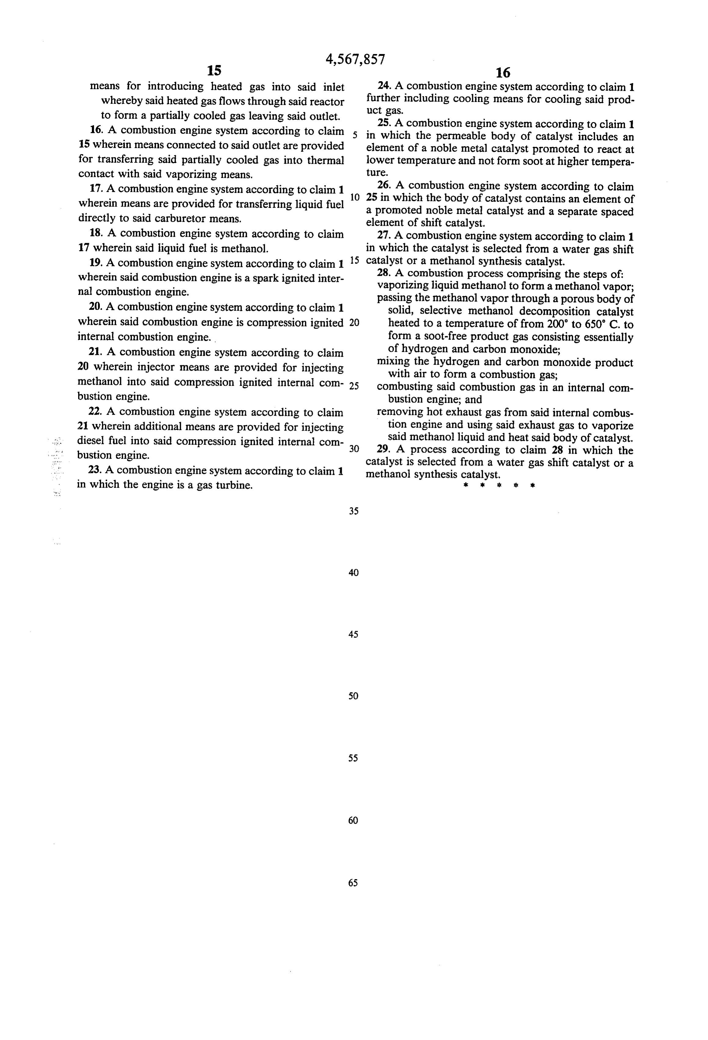
means for introducing heated gas into said inlet 24. A combustion engine system according to claim 1 whereby said heated gas flows through said reactor further including cooling means for cooling said prod to form a partially cooled gas leaving said outlet. uct gas.
16. A combustion engine system according to claim in 25. A combustion engine system according to claim 1 which the permeable body of catalyst includes an 15 wherein means connected to said outlet are provided element of a noble metal catalyst promoted to react at for transferring said partially cooled gas into thermal lower temperature and not form soot at higher tempera contact with said vaporizing means. ture.
17. A combustion engine system according to claim 1 10 26. A combustion engine system according to claim wherein means are provided for transferring liquid fuel a25promoted in which the body of catalyst contains an element of noble metal catalyst and a separate spaced directly to said carburetor means. element of shift catalyst.
18. A combustion engine system according to claim 27. A combustion engine system according to claim 1 17 wherein said liquid fuel is methanol. in which the catalyst is selected from a water gas shift 19. A combustion engine system according to claim 1 5 catalyst or a methanol synthesis catalyst. wherein said combustion engine is a spark ignited inter 28. A combustion process comprising the steps of: nal combustion engine. vaporizing liquid methanol to form a methanol vapor; passing the methanol vapor through a porous body of 20. A combustion engine system according to claim 1 solid, selective methanol decomposition catalyst wherein said combustion engine is compression ignited 20 heated to a temperature of from 200' to 650 C. to internal combustion engine. form a soot-free product gas consisting essentially 21. A combustion engine system according to claim of hydrogen and carbon monoxide; 20 wherein injector means are provided for injecting mixing the hydrogen and carbon monoxide product with air to form a combustion gas;
methanol into said compression ignited internal com 25 combusting said combustion gas in an internal com bustion engine. bustion engine; and 22. A combustion engine system according to claim removing hot exhaust gas from said internal combus 21 wherein additional means are provided for injecting tion engine and using said exhaust gas to vaporize diesel fuel into said compression ignited internal com 30 said methanol liquid and heat said body of catalyst. bustion engine. 29. A process according to claim 28 in which the 23. A combustion engine system according to claim 1 catalyst is selected from a water gas shift catalyst or a methanol synthesis catalyst, in which the engine is a gas turbine. k k six sk
Provenance
- Collection
- Cited prior art
- Original PDF
- patentimages.storage.googleapis.com →
- Filed
- 1982-08-16
- Pages
- 18
- Method
- pdftotext (the PDF's own text layer) + pdftoppm 300dpi page scans
- Source
- Google Patents bibliographic record
- Granted
- 1986-02-04
- Inventors
- John Houseman; Gerald E. Voecks; National Aeronautics and Space Administration NASA
- Transcribed from
- patentimages.storage.googleapis.com →