patent · US5115768
Combustion engine for hydrogen
26 May 1992
Page 1 — bibliographic record
United States Patent (19) 11 Patent Number: 5,115,768 Peschka et al. 45) Date of Patent: May 26, 1992 (54) COMBUSTION ENGINE FOR HYDROGEN 2525547 12/1976 Fed. Rep. of Germany ... 123/DIG.
(75 Inventors: Walter Peschka, Sindelfingen; OTHER PUBLICATIONS Gottfried Schneider, Stuttgart, both of Fed. Rep. of Germany Patent Abstracts of Japan, No. 54-52203, vol. 3, No. 76 73) Assignee: Deutsche Forschungsanstalt fuer (M-64), Jun. 29, 1979.
Patent Abstracts of Japan, No. 57-83626, vol. 6, No. 172
Luft-und Raumfahrt e.V., Fed. Rep. (M-154), Sep. 7, 1982.
of Germany
Primary Examiner-David A. Okonsky (21) Appl. No.: 652,325 Attorney, Agent, or Firm-Barry R. Lipsitz 22 Filed: Feb. 7, 1991 57 ABSTRACT (30) Foreign Application Priority Data In order to improve a combustion engine for hydrogen comprising a main piston which is displaceable in a main
Feb. 8, 1990 (DE) Fed. Rep. of Germany ....... 4003729 cylinder in a stroke direction between a top dead center, 51) Int. Cl. .............................................. FO2B 75/12 forming a minimum main cylinder chamber with the 52 U.S. C. ............................... 123/1 A; 123/59 BS; main cylinder, and a bottom dead center and hereby 123/289; 123/DIG. 12 performs a suction stroke, a compression stroke, a dis 58 Field of Search ........... 123/1 A, 269,289, 59 BS, placement stroke and an exhaust stroke, such that the 123/73 F, 65 S, 304,527, DIG. 12 problems of early ignition are avoided without any internal mixture formation with late injection being 56) References Cited required, it is recommended that an auxiliary piston and
an auxiliary cylinder be provided for movement relative to one another so as to be in equal phase and synchro 4,069,794 1/1978 Jordan ............................ 123/59 BS nous with the main piston and the main cylinder, that 4,367,698 1/1983 Skala ................................... 123/1 A the auxiliary piston and the auxiliary cylinder define 4,478,180 10/1984 Fujikawa et al ... 123/59 BS with one another a cylinder chamber varying between a 4,485,779 12/1984 Spurk. .................................. 23/289 minimum cylinder chamber in the top dead center and a 4,508,064 4/1985 Watanabe ................... 123/DIG. 12 maximum cylinder chamber in the bottom dead center, FOREIGN PATENT DOCUMENTS that the minimum cylinder chamber communicate with 568918 1/1933 Fed. Rep. of Germany . the minimum main cylinder chamber via a passage and 724065 7/1942 Fed. Rep. of Germany . that the hydrogen be injected into the cylinder chamber 851701 10/1952 Fed. Rep. of Germany . during the course of the suction stroke.
12 13 Claims, 3 Drawing Sheets
Page 2
Drawing sheet — no readable text.
Page 3
Drawing sheet — no readable text.
Page 4
Drawing sheet — no readable text.
Page 5
the hydrogen is injected into the cylinder chamber
COMBUSTION ENGINE FOR HYDROGEN during the course of the suction stroke. The inventive solution has the advantage that due to
The invention relates to a combustion engine for injection of the hydrogen into the cylinder chamber hydrogen comprising a main piston displaceable in a 5 during the suction stroke a relatively low pressure is main cylinder in a stroke direction between a top dead first required for this injection and a relatively long time center, forming a minimum main cylinder chamber with is available. In addition, the hydrogen is compressed in the main cylinder, and a bottom dead center and hereby the cylinder chamber during the compression stroke performing a suction stroke, a compression stroke, a and flows during this compression stroke through the displacement stroke and an exhaust stroke. O passage into the main cylinder chamber, leading to Combustion engines for hydrogen of this type are turbulences in the main cylinder chamber due to flow known. These can be operated in a number of different through the passage and these turbulences ensure that ways. A first possibility is the external mixture forma the hydrogen is mixed well with the air. Furthermore, tion with hydrogen with which the hydrogen/air mix 5 at the beginning of the compression stroke the hy ture is produced outside the cylinder chamber and this drogen/air mixture in the main cylinder chamber is not yet ignitable and does not become ignitable until imme is then drawn in as in a normal internal combustion engine for fossil fuels. diately prior to the top dead center being reached since it is not until this time that the hydrogen is more or less
Another possibility is the internal mixture formation completely which provides for injection of the hydrogen directly 20 main cylinder expelled from the cylinder chamber into the into the main cylinder chamber, a difference being made chamber.
between an early injection, i.e. at the beginning of the vantages of thetheinternal
In this way, inventive solution combines the ad mixture formation with early compression stroke, and a late injection, i.e. injection injection, relating to the time available for injecting the substantially near to the end of the compression stroke. hydrogen and the low pressures
In contrast to internal combustion engines for fossil 25 vantages of the internal mixturerequired, formation and the ad with late fuels, in the case of combustion engines for hydrogen injection with a view to the fact that early ignition power losses result both with the external mixture for avoided since the mixture in the main cylinder chamberis mation with hydrogen and with the internal mixture formation with early injection in the range of full load doesately not become ignitable until more or less immedi prior to the top dead center being reached.
due to uncontrolled early ignition since the hydrogen 30 According to the invention, the main cylinder cham /air mixture is heated at hot parts of the engine and ber and the cylinder chamber are separated in all stroke therefore ignites prematurely. positions and connected via the passage. This uncontrolled early ignition can be avoided when Theoretically, the auxiliary cylinder and the auxiliary using internal mixture formation with late injection of piston can be arranged independently of the main piston hydrogen since the ignitable hydrogen/air mixture does 35 and main cylinder and a transfer passage provided be not result until towards the end of the compression tween the two. It is, however, particularly advanta stroke. geous for the passage to be at least partially formed by However, the internal mixture formation with late a gap between the auxiliary piston and the auxiliary injection does have the disadvantage that is it very cylinder. This means that due to the relative movement difficult to homogenize the mixture sufficiently for 40 of auxiliary piston and auxiliary cylinder control of the combustion and so local inhomogeneities constantly transfer velocity from the cylinder chamber into the result and these lead to a high emission of nitrogen main cylinder chamber is possible, in addition. oxide. In addition, problems also occur, at the custom This control possibility can be achieved particularly ary speeds of internal combustion engines, when trying easily in that the smallest radial distance of the gap to inject, distribute and ignite the required volume of 45 between the auxiliary piston and the auxiliary cylinder hydrogen in the combustion chamber during the short varies between the top dead center and the bottom dead time available. This requires, for example, in the initial center.
load range injection pressures in the order of 100 to 200 In the embodiments described thus far, the auxiliary bars in view of the greater volume of hydrogen in com cylinder and the auxiliary piston can, as already men parison with fossil fuels having the same energy con 50 tioned, be arranged independently of the main piston tent. and main cylinder. It is, however, particularly advanta The object underlying the invention is therefore to geous for the auxiliary piston and the auxiliary cylinder improve a combustion engine for hydrogen such that to be displaced relative to one another in the stroke the problems of early ignition are avoided without any direction of the main piston, i.e. both move in the same internal mixture formation with late injection being 55 direction as the main piston.
necessary. From a constructional point of view, the inventive This object is accomplished in accordance with the combustion engine can be realized in a particularly invention, for a combustion engine of the type described simply manner by the auxiliary piston and the auxiliary at the outset, in that an auxiliary piston and an auxiliary cylinder travelling, relative to one another, along the cylinder are provided for movement relative to one same path as the main piston. Particularly in the latter another so as to be in equal phase and synchronous with case, the synchronous coupling of the movement of the the main piston and the main cylinder, that the auxiliary auxiliary piston relative to the auxiliary cylinder with piston and the auxiliary cylinder define with one an the main piston is achieved by coupling the displaceable other a cylinder chamber varying between a minimum auxiliary piston or auxiliary cylinder, respectively, with cylinder chamber in the top dead center and a maximum 65 the main piston via a connecting member. cylinder chamber in the bottom dead center, that the This connecting member can be of the most varied minimum cylinder chamber communicates with the type and construction. For example, it is possible to minimum main cylinder chamber via a passage and that provide a coupling rod as connecting member.
Page 6
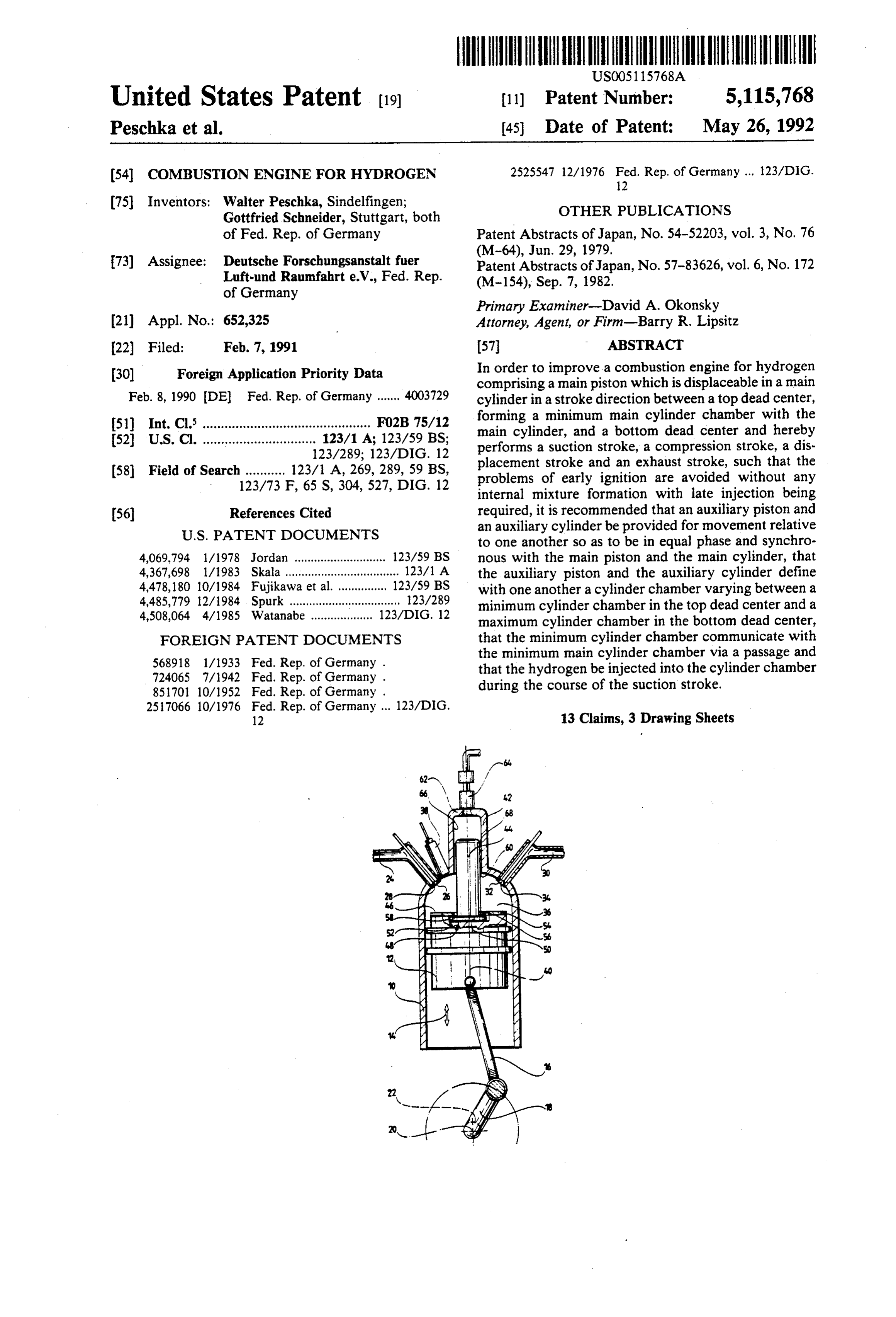
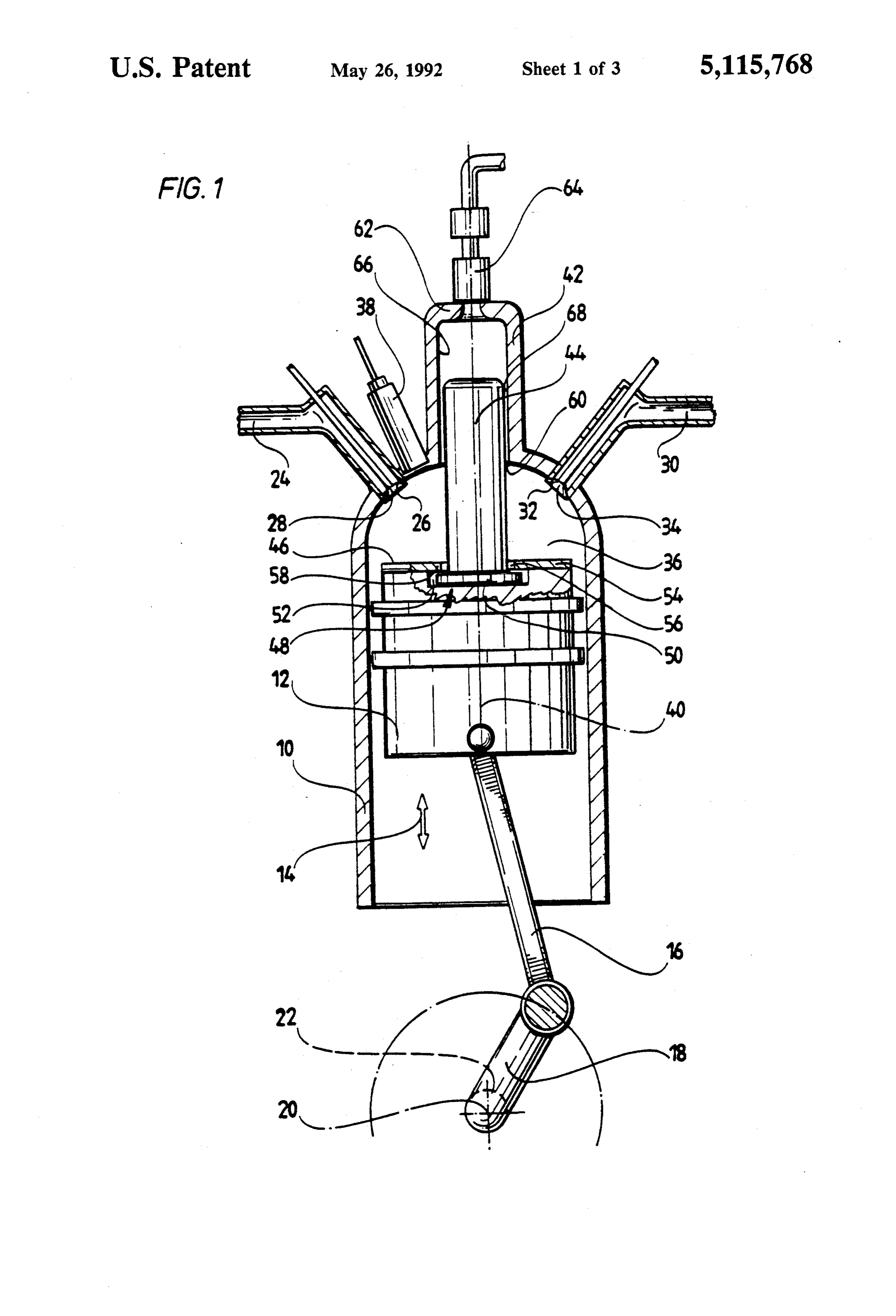
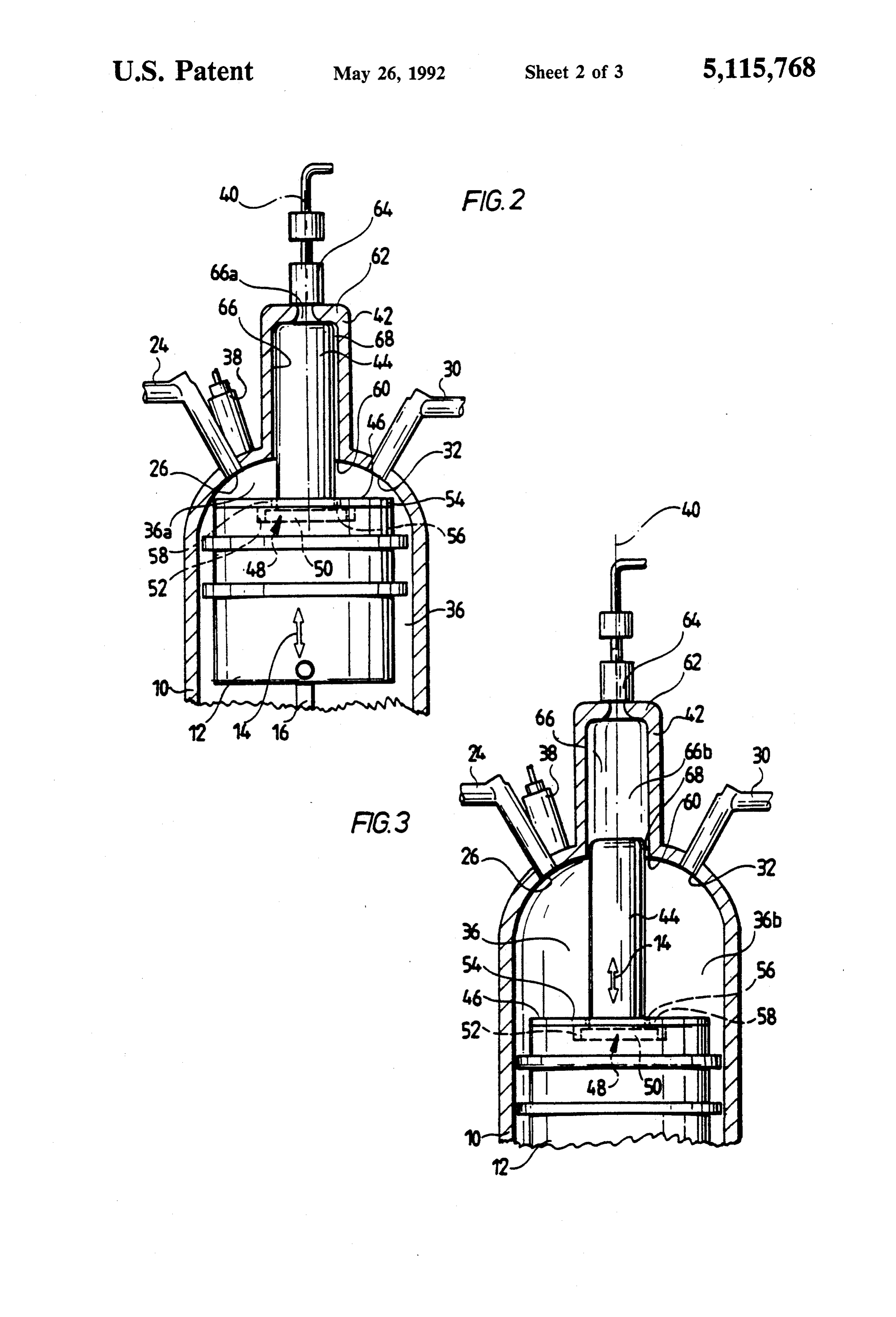
In the simplest case, however, the stationary auxiliary main cylinder chamber 36a while the main piston 12 in cylinder or auxiliary piston is rigidly connected to the its bottom dead center illustrated in FIG. 3 encloses main cylinder and the displaceable auxiliary piston or with the main cylinder 10 a maximum main cylinder auxiliary cylinder is held on the main piston. In this chamber 36b.
case, the two movable parts are rigidly held on one Ignition of a hydrogen/air mixture present in the another so that synchronous movement thereof is possi main cylinder chamber 36 is carried out by an ignition ble in the simplest manner. element 38.
In order to achieve compensation for play and, in The main piston 12 is arranged coaxially to a cylinder particular, to ensure that the gap between auxiliary axis 40 of the main cylinder 10 and moves parallel cylinder and auxiliary piston can readjust itself, the 10 thereto in the stroke direction 14. auxiliary piston or auxiliary cylinder, respectively, is An auxiliary cylinder 42 is linked with the main cylin held on the main piston with clearance transverse to the der 10 and this is arranged coaxially to the cylinder axis stroke direction so that the two movable parts can still, 40 and extends away from the main piston 12. An auxil relative to one another, move transversely to the stroke iary piston 44 is mounted for displacement in this auxil direction to provide such compensation for play. 5 iary cylinder 42 and this piston is also arranged coaxi In the simplest case, the auxiliary piston extends be ally to the cylinder axis 40 and rises above a base 46 of yond a base of the main piston. the main piston 12 in the direction of the auxiliary cylin In addition, in this case the auxiliary cylinder extends der 42.
away from the minimum cylinder chamber. The auxiliary piston 44 is preferably held non-dis Particularly when relative movement of the auxiliary placeably in the stroke direction 14 on the main piston cylinder and the auxiliary piston is intended to be in the 12 with an auxiliary piston foot 48. This auxiliary piston stroke direction, the auxiliary cylinder extends in the foot 48 comprises an annular flange 50 which is located stroke direction of the main piston and preferably forms in a recess 52 arranged on the base side in the main an extension of the main cylinder. piston 12 and is held in this recess by a base cover 54 Particularly advantageous is, in addition, an embodi 25 having an opening 56 and an edge region 58 surround ment of the inventive combustion engine, in which this ing the opening 56 which engages over the annular is provided with a main injection means opening into flange 50.
the main cylinder chamber and generating a weak oper The opening 56, through which the auxiliary piston ation during the suction stroke and in which for enrich 44, proceeding from its auxiliary piston foot 48, projects ing the mixture an enriching injection means is provided 30 beyond the base 48 in the direction of the auxiliary in the cylinder chamber. cylinder 42, and the recess 52 are preferably dimen This has the advantage that the basic enrichment of sioned such that the auxiliary piston foot 48 has clear the hydrogen/air mixture is carried out via the injection ance in the radial direction relative to the cylinder axis directly into the main cylinder chamber and so auxiliary 40 and so can move to a slight extent in the radial direc cylinder and auxiliary piston can be of a very small 35 tion relative to the cylinder axis 40 in order to con construction as these merely have to perform an enrich stantly take up a central position relative to the auxiliary ing injection and so the inventive combustion engine is, piston 44.
altogether, of a very small construction. In the simplest case, the auxiliary piston 44 is com Additional features and advantages of the inventive pletely cylindrical and the auxiliary cylinder 42 is also solution are the subject matter of the following descrip designed to be cylindrical to the cylinder axis 40 and tion as well as of the drawings of several embodiments. extends from an auxiliary cylinder opening 60 in the In these drawings: main cylinder 10 to an auxiliary cylinder head 62 which FIG. 1 shows a first embodiment illustrated schemati closes the auxiliary cylinder 42. A hydrogen injector 64 cally in cross section; is inserted into the auxiliary cylinder head 62 and this FIG. 2 is an illustration similar to FIG. 1 of the first 45 injects hydrogen of, for example, 15 bars, into the auxil embodiment in the top dead center; - iary cylinder 42.
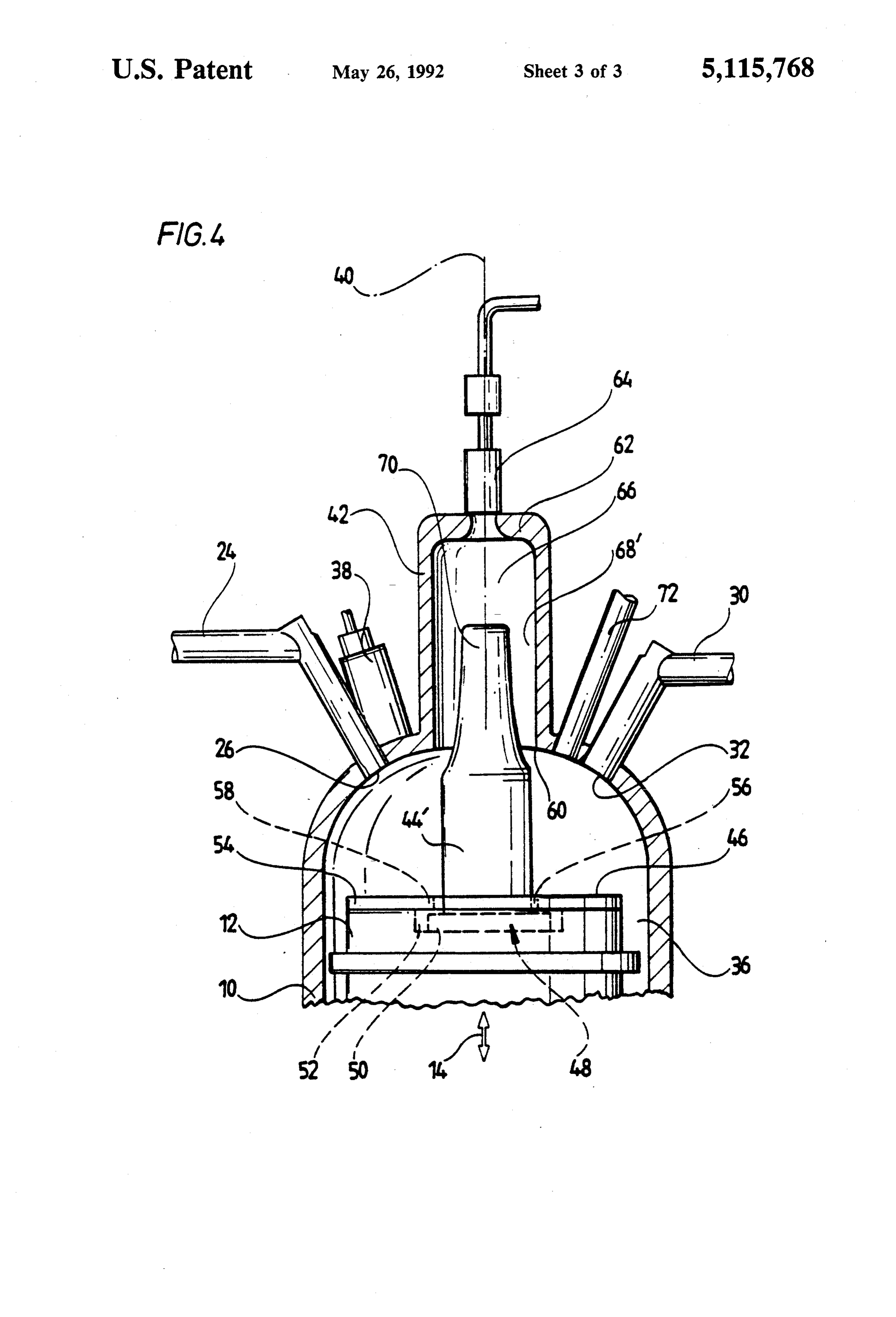
FIG. 3 is an illustration similar to FIG. 1 of the first The auxiliary piston 44 forms with the auxiliary cylin embodiment in the bottom dead center and der 42 a cylinder chamber 66 which, in the top dead FIG. 4 is an illustration similar to FIG. 1 of a second center of the main piston 12, is the minimum cylinder embodiment. 50 chamber 66a and, in the bottom dead center of the main A first embodiment of an inventive combustion en piston 12, the maximum cylinder chamber 66b. gine for hydrogen, illustrated in FIG. 1, comprises a The cylinder chamber 66 communicates with the main cylinder 10 in which a main piston 12 is adapted main cylinder chamber 36 via a gap 68 formed between for reciprocating movement in a stroke direction 14, the auxiliary piston 44 and the auxiliary cylinder 42, i.e. between a top dead center illustrated in FIG. 2 and a 55 its cylinder surfaces. This gap is intentionally large in bottom dead center illustrated in FIG. 3. The main design and represents a transfer passage between the piston 12 is connected by way of a piston rod 16 to a cylinder chamber 66 and the main cylinder chamber 36. crankshaft 18 which, itself, rotates about an axis 20 of a The inventive combustion engine, illustrated in driven shaft 22 of the combustion engine. An inlet pas FIGS. 1 and 3, operates as follows: sage 24 opens into the main cylinder 10 in an inlet open During a suction stroke the main piston 12 moves ing 26 which is adapted to be closed by an inlet valve together with the auxiliary piston 44 from the top dead 28. In addition, an outlet passage 30 leads from the main center, illustrated in FIG. 2, to the bottom dead center, cylinder 10, starting from an outlet opening 32 which is illustrated in FIG. 3. In this case, the inlet opening 26 is also adapted to be closed by an outlet valve 34. released by the inlet valve 28 so that air can flow into A main cylinder chamber 36 is enclosed by the main 65 the main cylinder chamber 36 through the inlet passage piston 12 and the main cylinder 10. 24. At the same time, hydrogen at a pressure of approxi In its top dead center illustrated in FIG. 2, the main mately 10 to 20 bars is injected into the cylinder cham piston 12 with the main cylinder 10 encloses a minimum ber 66 via the hydrogen injector 64. Since the gap 68 is
Page 7
very small in dimension, only a very small amount of present in the main cylinder chamber is far removed the hydrogen flows into the main cylinder chamber 36 from being capable of igniting, whereas towards the end and so an extremely weak hydrogen/air mixture is of the compression stroke, when the hydrogen/air mix formed therein and this is not ignitable. ture in the main cylinder chamber 36 is close to being During a compression stroke the main piston 12 ignitable, a lesser amount of hydrogen flows into this moves together with the auxiliary piston 44 from the chamber and, consequently, the hydrogen/air mixture bottom dead center, illustrated in FIG. 3, to the top in the main cylinder chamber 36 will be kept below its dead center, illustrated in FIG. 2. The increasing com ignitability more or less until the top dead center is pression in the cylinder chamber 66 now results in an reached and this ignitability is not reached until more or increasing amount of the hydrogen flowing from the O less immediately before the top dead center. cylinder chamber 66 via the gap 68 into the main cylin In addition, the second embodiment is also provided der chamber 36a and increasingly enriching the ex with a main injection means 72 which opens directly tremely weak hydrogen/air mixture therein but leaving into the main cylinder chamber 36 and serves to inject this so weak over broad regions of the compression hydrogen directly into the main cylinder chamber dur stroke that this is not ignitable and the hydrogen/air 15 ing the suction stroke.
mixture in the main cylinder chamber 36 is not enriched This second embodiment operates, in contrast to the enough to be ignitable until towards the end of the first embodiment, such that the major amount of hydro compression stroke. This means that an ignitable mix gen is injected via the main injection means 72 during ture does not result in the main cylinder chamber 36 the suction stroke so that a hydrogen/air mixture is until shortly before the top dead center is reached and 20 already formed in the main cylinder chamber 36, this so the mixture formation is comparable with respect to major amount being determined such that the mixture its ignitability to the internal mixture formation having thus resulting is a weak mixture which has no or only a late commencement of injection, i.e. commencement of negligible ignitability.
injection in the vicinity of the top dead center.
This avoids the problem of early ignition occurring in 25 theThe remaining hydrogen is, as before, injected into cylinder chamber 66 via the injector 64 and injected the internal mixture formation with early injection.
Moreover, the displacement of the hydrogen out of the course ofcylinder into the main the chamber 36 via the gap 68 during compression stroke so that the opti the cylinder chamber 66 and the transfer thereof mum ignitable mixture again does through the gap 68 into the main cylinder chamber 36 the end of the compression stroke.not result until near Thus, the same ad causes, in the main cylinder chamber, a very strong 30 vantages can be achieved as with the first embodiment. turbulence in the hydrogen together with the com pressed air and so, consequently, the hydrogen/air mix to The advantage of the second embodiment according FIG. 4 is to be seen in the fact that the auxiliary ture is very well mixed locally due to the resulting cylinder 42 and the auxiliary piston 44 can be of a turbulences.
During the subsequent combustion stroke the main 35 smaller construction and therefore the entire combus piston 12 and the auxiliary piston 44 non-displaceably tion engine can be built in a more space-saving manner since a smaller amount of hydrogen is injected into the connected therewith in the stroke direction 14 move from the top dead center to the bottom dead center cylinder chamber 66 and from there transferred to the while the main cylinder chamber 36 expands and during main cylinder chamber 36.
The present disclosure relates to the subject matter the subsequent exhaust stroke the combusted hydrogen /air mixture is expelled through the outlet opening 32, disclosed in German application No. P4003 729.0 of with the outlet valve 34 open, via the outlet passage 30. Feb. 8, 1990, the entire specification of which is incor Subsequently, this combustion engine commences a porated herein by reference.
What is claimed is:
new cycle of operation.
In a second embodiment of the inventive combustion 45 1. Combustion engine for hydrogen comprising a engine, illustrated in FIG. 4, the auxiliary piston 44' is, main piston displaceable in a main cylinder in a stroke in contrast to the auxiliary piston 44, not completely direction between a top dead center, forming a mini cylindrical in design but narrows in its central portion mum main cylinder chamber with the main cylinder, 70 so that the width of the gap 68" formed between the and a bottom dead center and hereby performing a auxiliary cylinder 42 and the auxiliary piston 44' and, 50 suction stroke, a compression stroke, a displacement therefore, the width of the transfer passage between the stroke and an exhaust stroke, characterized in that an cylinder chamber 66 and the main cylinder chamber 36 auxiliary piston (44) and an auxiliary cylinder (42) are varies between the top and bottom dead centers accord be provided for movement relative to one another so as to ing to the position of the auxiliary piston 44'. in equal phase and synchronous with the main piston For example, the width of the gap 68" is large during 55 (12) and the main cylinder (10), that the auxiliary piston a compression stroke, starting from the bottom dead (44) and the auxiliary cylinder (42) define with one center, and so at the beginning of the compression another a cylinder chamber (66) varying between a stroke a slighter volume of hydrogen is displaced out of minimum cylinder chamber (66a) in the top dead center the auxiliary cylinder 44, although this can easily reach and a maximum cylinder chamber (66b) in the bottom the main cylinder chamber 36 due to the larger width of 60 dead center, that the minimum cylinder chamber (66a) the gap 68", whereas once the central region 70 has communicates with the minimum main cylinder cham passed through the auxiliary cylinder opening 60 the ber (36a) via a passage (68) and that the hydrogen is gap 68" is less wide and so the hydrogen from the cylin injected into the cylinder chamber (66) during the der chamber 66 can no longer flow so easily into the course of the suction stroke.
main cylinder chamber 36. This means, for example, 65 2. Combustion engine as defined in claim 1, character that at the beginning of the compression stroke the ized in that the passage is at least partially formed by a hydrogen can easily be transferred into the main cylin gap (68) between the auxiliary piston (44) and the auxil der chamber 36, as long as a hydrogen/air mixture iary cylinder (42).
Page 8
3. Combustion engine as defined in claim 2, character 8. Combustion engine as defined in claim 7, character ized in that the smallest radial width of the gap (68) ized in that the auxiliary piston (44) or auxiliary cylinder between the auxiliary piston (44) and the auxiliary cylin (42) is held on the main piston (12) with clearance trans der (42) varies between the top dead center and the verse to the stroke direction (14). bottom dead center. 9. Combustion engine as defined in claim 7, character 4. Combustion engine as defined in claim 1, character ized in that the auxiliary piston (44) rises above a base ized in that the auxiliary piston (44) and the auxiliary (46) of the main piston (12).
10. Combustion engine as defined in claim 1, charac cylinder (42) move relative to one another in the stroke terized direction (14) of the main piston (12), in that the auxiliary cylinder (42) extends away 10 from the minimum cylinder chamber (36a).
5. Combustion engine as defined in claim 1, character 11. Combustion engine as defined in claim 10, charac ized in that the auxiliary piston (44) and the auxiliary terized in that the auxiliary cylinder (42) extends in the cylinder (42) travel, relative to one another, along the stroke direction (14) of the main piston (12). same path as the main piston (12). 12. Combustion engine as defined in claim 10, charac 6. Combustion engine as defined in claim 1, character 5 terized in that the auxiliary cylinder (42) forms an exten ized in that the displaceable auxiliary piston (44) or sion of the main cylinder (10).
auxiliary cylinder (42), respectively, is coupled to the 13. Combustion engine as defined in claim 1, charac main piston (12) via a connecting member (48). terized in that the combustion engine is provided with a 7. Combustion engine as defined in claim 6, character main injection means (72) opening into the main cylin ized in that the stationary auxiliary cylinder (42) or 20 der chamber (36) and generating a weak mixture during auxiliary piston (44) is rigidly connected to the main the suction stroke, and that for enriching the mixture an cylinder (10) and that the displaceable auxiliary piston enriching injection means (64) into the cylinder cham (44) or auxiliary cylinder (42), respectively, is held on ber (66) is provided. k the main piston (12).
Provenance
- Collection
- Cited prior art
- Original PDF
- patentimages.storage.googleapis.com →
- Filed
- 1991-02-07
- Pages
- 8
- Method
- pdftotext (the PDF's own text layer) + pdftoppm 300dpi page scans
- Source
- Google Patents bibliographic record
- Granted
- 1992-05-26
- Inventors
- Walter Peschka; Gottfried Schneider; Deutsches Zentrum fuer Luft und Raumfahrt eV
- Transcribed from
- patentimages.storage.googleapis.com →