patent · US20100051449A1
Method and apparatus for controlling an electric motor
4 March 2010
Page 1
(19) United States (12) Patent Application Publication (10) Pub. No.: US 2010/0051449 A1
Gammons et al. (43) Pub. Date: Mar. 4, 2010 (54) METHOD AND APPARATUS FOR Publication Classification
CONTROLLING ANELECTRIC MOTOR
(76) I nVentOrS: RickV L. G icky L. Gammons, Laf
Lafayette, TN C25D 17/00 (2006.01)
(US); Zachary A. Henry, SR., (52) U.S. Cl. ........................................................ 204/212 Corryton, TN (US) (57) ABSTRACT
Correspondence Address: Method and apparatus for controlling an electric motor PITTS AND BRITTIAN PC employing an electrolysis Subassembly connected in an elec trical circuit which includes the electric motor. While con
KNOXVILLE, TN 37950-1295 (US) trolling the throughput of electrical current through the elec trolysis Subassembly, there is simultaneously generated a fuel gas useful for fueling an internal combustion engine. The (21) Appl. No.: 12/203,621 invention includes a novel electrolyte utilizing novel elec trode structure and mode of operation. The electrolysis may (22) Filed: Sep. 3, 2008 be powered by a battery pack.
Page 2
Drawing sheet — no readable text.
Page 3
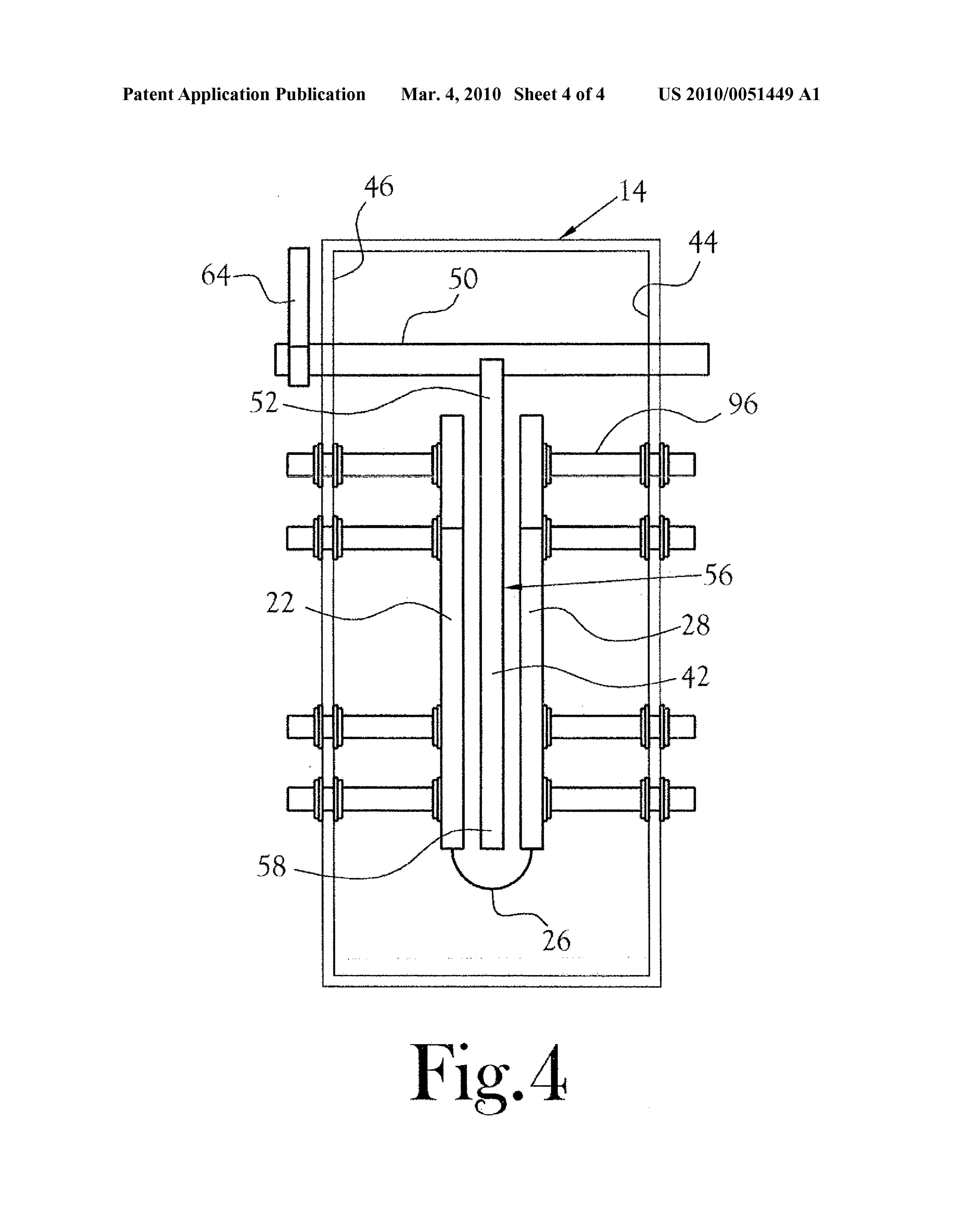
Drawing sheet — no readable text.
Page 4
Drawing sheet — no readable text.
Page 5
Drawing sheet — no readable text.
Page 6
US 2010/005 1449 A1 Mar. 4, 2010
METHOD AND APPARATUS FOR had only limited Success for various reasons such as cost, CONTROLLING ANELECTRIC MOTOR availability, Storage and delivery to consumers, etc. CROSS-REFERENCE TO RELATED SUMMARY OF INVENTION
APPLICATIONS
0007. In accordance with one aspect of the present inven 0001. Not Applicable tion there is provided a method and apparatus for controlling motors, either an electric motor, an ICE or both an electric motor and an ICE, in combination, at times simultaneously.
STATEMENT REGARDING FEDERALLY The controller of the present invention employs electrolysis SPONSORED RESEARCH ORDEVELOPMENT of a novel electrolyte utilizing novel electrode structure and mode of operation, thereby producing a novel fuel gas under 0002. Not Applicable controlled conditions. Such controlled conditions preferably include the control of that quantity per unit of time of elec
FIELD OF INVENTION trical energy throughputted by the electrolysis unit for driving an electric motor or that quantity per unit of time of a gaseous 0003. This invention relates to methods and apparatus for stream generated within the electrolysis for fueling an ICE, controlling the operation of an electric motor or an internal for example. That is, in the present invention, there exists the ability to simultaneously control electrical power being fed combustion engine (ICE). As a beneficial byproduct, there is through an electrolysis unit to an electric motor and a fuel gas generated a Volume of hydrogen gas Suitable for a variety of for an ICE employing the same source of potential energy. USS.
0008 For present purposes, the term “fuel gas may include a single gas (e.g. hydrogen) or a mixture of gases (e.g.
BACKGROUND OF INVENTION hydrogen, oxygen, water vapor or steam and/or other chemi calentities). Moreover, a fuel gas of the present invention may 0004 Electric motors commonly require means to control include minor and/or non-essential components either alone the operational speed of the motor(s). For example, in the or combined with hydrogen, oxygen or nitrogen, for example. prior art, control over the speed of rotation of the motor rotor, Thus the term “fuel gas' should be understood to include a hence the rotational output of the motor shaft, has taken the single gas or a mixture of gases as the context dictates, Sug form of variable resistors, rheostats, and like devices for gest or implies. Moreover, herein, the term motor may be adjusting the electrical input employed to drive the motor, employed to designate either an electrically powered motor Such as the input Voltage or amperage of the current being fed (ac or dc) or an ICE depending upon the context in which the term is used.
to the motor. Such prior art devices most commonly generate significant amounts of heat during operation of the motor. 0009. As noted, in accordance with the present invention, They further commonly are limited to specific ranges of elec the novel fuel gas is generated onsite. Such as onboard a motor trical input, e.g. between “X” and “Y” volts, “X” and “Y” vehicle, or at a site remote from commonly employed sources being chosen, among other things, to provide Sufficient power of power for driving an electric motor, for example. for driving the motor, while minimizing the heat generated by 0010. The electrolysis process of the present invention the control device. Such devices are subject to damage by may be powered by a battery or battery pack in an electrical circuit which includes the motor. The electrodes of the elec overheating and/or electrical spikes (both high and low) and/ trolysis unit include first and second, preferably planar, elec or overvoltage or undervoltages. trically conductive plates, which are electrically connected to 0005 Electronic motor controllers have been employed. collectively define a first electrode. These parallel plates are These controllers may exhibit lesser heat problem, but they mounted in registered, spaced-apart, Substantially parallel are most sensitive to damage by electrical spikes and/or over planar relationship to one another within the electrolyte and Voltages or undervoltages. In some instances, these devices are adjustable with respect to their spaced apart spatial rela overheat and have been known to be the source of disastrous tionship. There is further included a planar second plate elec fires. trode of Substantially like size and geometry as the first and 0006 Control of the operation of internal combustion second plates of the first electrode. This second electrode is engines (ICEs) is conventionally achieved employing control moveable between a first position out of the electrolyte (hence over the quantity of a stream of combustible gas(es) intro out of register with the plates of the first electrode) and a duced to the engine by means of a carburetor, for example. second position within the electrolyte and partially or sub Fuel injection also has been employed in similar manner. In stantially fully interposed between the first and second plates, each instance, the concept involves feeding of a suitable mix and Substantially equidistant from, and aligned (in register) ture of air and a combustible gas such as petroleum-based with the first and second plates of the first electrode. Accord products (gasoline, diesel fuel, etc.) and fuels labeled as bio ing to one aspect of the present invention, the degree of mass fuels, hydrogen, and the like. Alternatively, the prior art registration of the second electrode with the first and second has also included the concept of employing electric motors in plates of the first electrode establishes the rate of electrolysis addition to, or in lieu of ICEs. Alternative fuel(s) are actively of the electrolyte, hence the control of voltage drop across the being sought which can reduce the adverse effects on the electrolysis unit, hence provides for control, in the nature of a environment attributable to their use and/or which are less variable resistor, over the operation of an electric motor which expensive than currently available fuels and/or whose sources is electrically connected in an electrical circuit with the elec are abundantly available and, renewable. Combinations of trolysis unit. A stream of fuel gas emanates from the elec these fuels and other motor vehicle powering concepts have trolysis unit of the present invention. This fuel gas may be
Page 7
US 2010/005 1449 A1 Mar. 4, 2010
directed to any of several beneficial uses, a principal one of posed within the length of the conduit, there may be provided which is to fuel the operation of an ICE. a cooling device, such as a radiator 40 capable of cooling the 0011. In accordance with a further aspect of the present electrolyte flowing from the second tank into the first tank invention, the overall energy output from the electric motor within a selected desired range of temperatures. Power for has been found to be sufficient to provide a degree of opera operation of this pump is provided by the battery pack 12. By tional energy output from the electric motor to drive a variety this cooling means, heat generated within the electrolysis unit of equipment and also to provide Sufficient excess energy for is dissipated via the radiator so that the temperature of the charging of the battery pack employed to power the electroly electrolyte within the first tank can be maintained substan sis unit under useful operational conditions. Still further, as tially constant at a preselected value or range of values. This desired, all or a portion of the gaseous output stream from the factor further serves to maintain the level of effective electro electrolysis unit may be captured and stored for future use. lyte contained within the first tank Substantially constant as the electrolyte is depleted over time. Moreover, this same
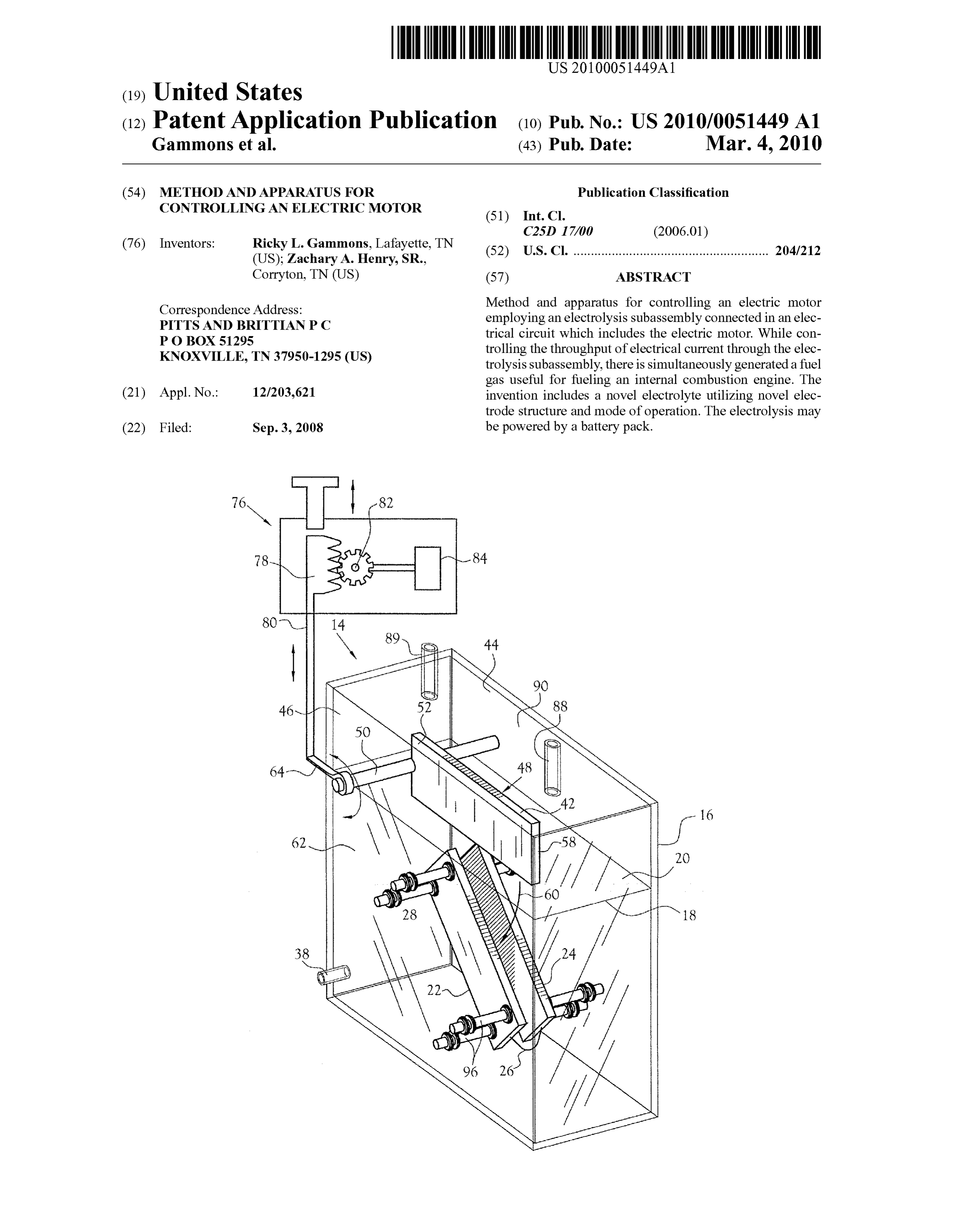
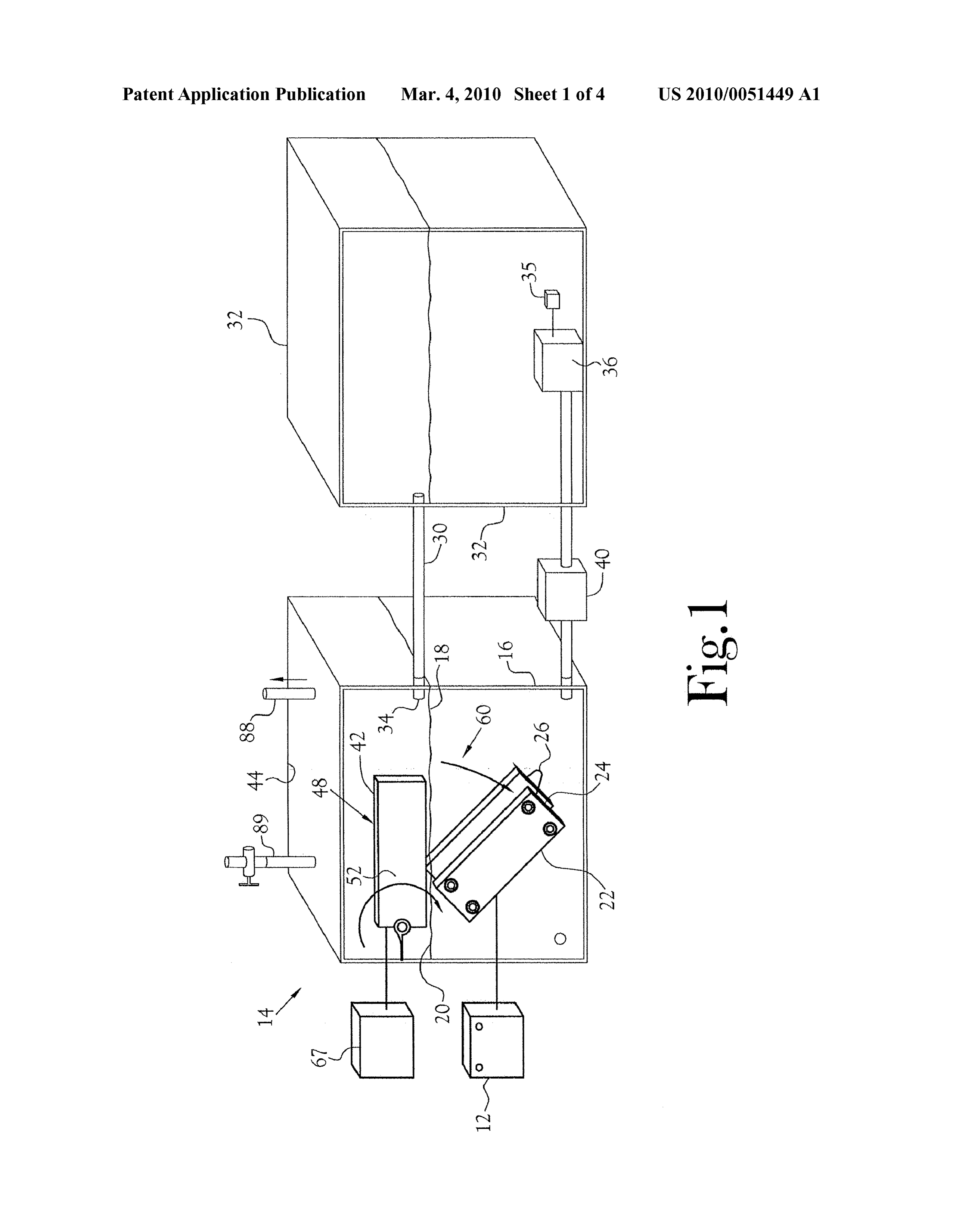
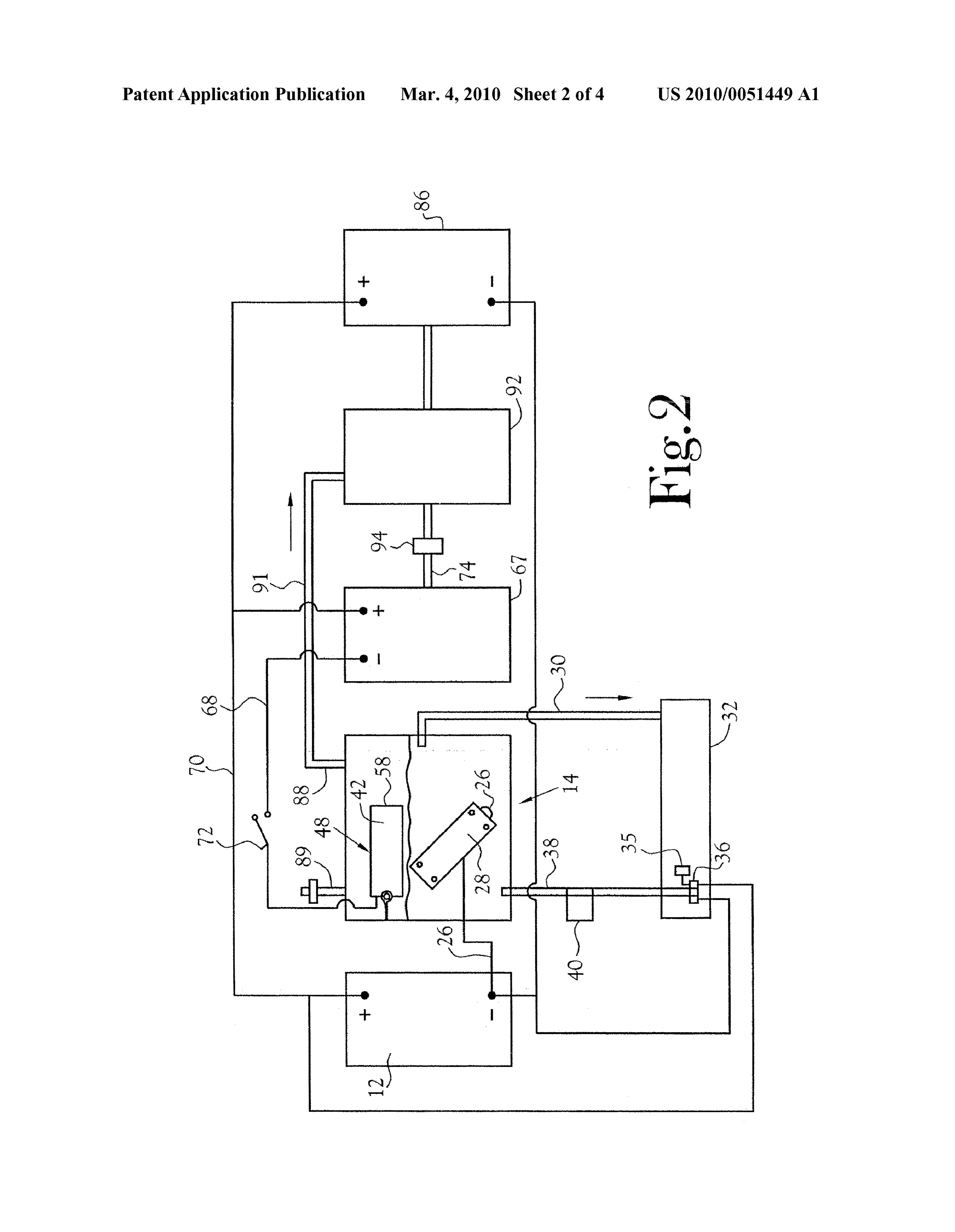
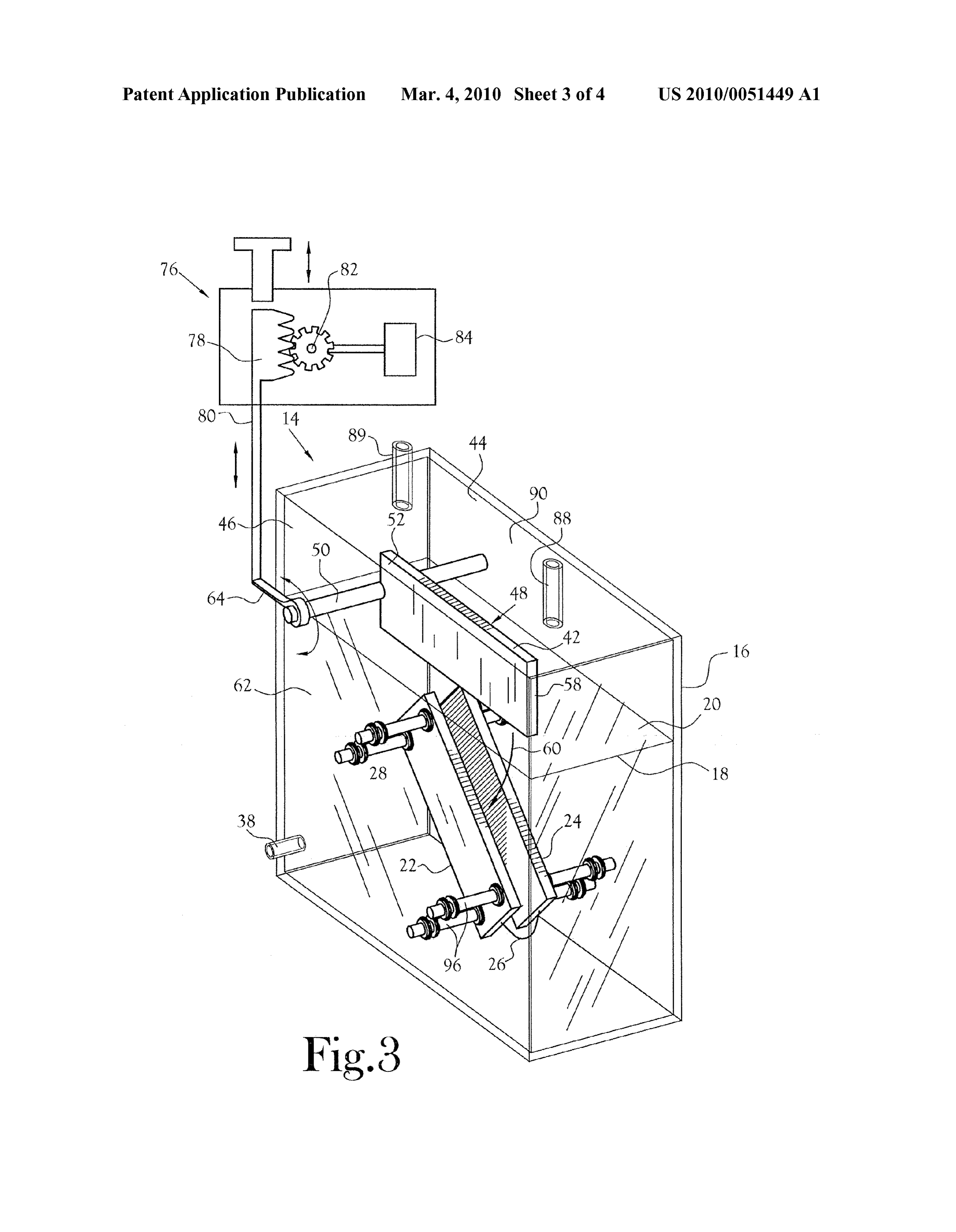
BRIEF DESCRIPTION OF THE FIGURES factor enhances the retention of a constant composition of the electrolyte within the first tank, thereby contributing to the 0012 FIG. 1 is a schematic representation of one embodi generation of an electrical throughput from the electrolysis ment of the system of the present invention; unit which is Substantially constant over time for any given 0013 FIG. 2 is further schematic representation of the rate of electrolysis of the electrolyte within the first tank. system of FIG. 1 and including a diagrammatic representation 0018. As further depicted in FIG. 1, there is provided a of one embodiment of electrical circuitry, among other fea second electrode 42 mounted within the first tankata location tures, associated with the system depicted in FIG. 1; between opposite side walls 44 and 46, whereby this second 0014 FIG. 3 is a perspective schematic representation of electrode is movable between a first position 48 out of the one embodiment of an electrolysis unit useful in the present electrolyte disposed within the first tank and a position within invention; and the electrolyte within the first tank. This second electrode is 0015 FIG. 4 is an end plan view of an electrolysis unit as desirably of substantially the same geometry and dimensions depicted in FIG. 3. as each of the first and second plates of the first electrode. In
DETAILED DESCRIPTION OF INVENTION
the depicted embodiment, this second electrode is mounted on a shaft 50, for example, located adjacent one end 52 of the 0016 FIG. 1 depicts one embodiment of apparatus useful second electrode, for movement within a plane which can for carrying out various aspects of the present invention. The result in the second electrode being disposed between, spaced depicted apparatus includes a battery pack 12 which serves as Substantially equidistantly apart from, and Substantially par a source of electrical energy for powering an electrolysis unit allel with respect to the planar orientations of the first and 14. In the embodiment depicted in FIG.1, the electrolysis unit second plates of the first electrode. (See FIG. 3). includes a first tank 16 adapted to contain a quantity of an 0019. As depicted in FIGS. 3 and 4, in one embodiment of electrolyte 18. Also contained within the first tank and at a the second electrode 42 and its mounting within the first tank level beneath the upper surface 20 of the electrolyte within the and into and out of the electrolyte, the second planar electrode tank, are first and second plates 22 and 24, respectively. has one end 52 thereof mounted on a stub shaft 50 which is Referring to FIGS. 1-4, these two plates are adjustably mounted between the opposite side walls 44 and 46 of the first mounted, by means of bolts 96 within the first tank beneath tank at a level sufficiently above the surface level 20 of the the upper surface level of the electrolyte disposed within the electrolyte disposed within the first tank as permits the move first tank, for selectively adjusting their spatial relationship. ment of this second electrode between its first position 48 As seen in FIGS. 3 and 4, these plates are disposed in spaced fully out of the electrolyte and its second position 56 (FIG. 4) apart, registered, parallel relationship to one another. Further, of partially or substantially in register with, and between the these two plates are electrically connected to one another as first and second plates of the first electrode. In the depicted by means of an electrical conductor 26 in a manner which embodiment of FIG.3, rotation of the stub shaft 50 swings the causes these plates to collectively define a single electrode, outboard end 58 of the second electrode along a curved path deemed the first electrode 28 for purposes of the present 60 to move this second electrode between its first and second invention. positions. Rotation of the stub shaft may be effected by any of 0017. The electrolyte-containing first tank 16 is connected several means. In FIG. 3, the stub shaft projects through the in fluid flow communication as by a conduit 30, with a second wall 44 of the first tank and beyond the outer surface of the tank 32 which is adapted to receive and contain a quantity of wall. That portion of the stub shaft which projects beyond the electrolyte in reserve for selective transfer into and/or through outer surface of the tank wall includes a lever arm 64 attached the first tank. In the depicted embodiment, the conduit inter thereto, the movement of which may effect rotation of the connecting the first and second tanks includes an inlet end 34 second electrode as desired. By means of the adjustability of which is disposed slightly below the surface level 28 of a the spacing between the first and second plates of the first desired quantity of electrolyte contained in the first tank. electrode, a Substantially unlimited electrical resistance range Thus, electrolyte from the first tank will freely flow by gravity with unlimited voltage drop within the range of the battery from the first tank into the second tank so long as the level of pack may be achieved employing the present electrolysis electrolyte in the first tank remains above the level of the input unit end of the conduit leading to the second tank. For purposes of 0020. From the foregoing, it will be recognized that move ensuring controlled flow of electrolyte from the second (re ment of the second electrode into the electrolyte and between serve) tank into the first tank, there may be provided a ther the first and second plates of the first electrode establishes a mostat-controlled 35 pump 36 submerged within the electro variable resistance path for the movement of ions and elec lyte in the second tank. The output flow of electrolyte from trons causing a flow of electrical current between the first and this pump is fed through a conduit 38 to the first tank. Inter second plates of the first electrode and the second electrode
Page 8
US 2010/005 1449 A1 Mar. 4, 2010
with resultant controlled flow of an electrical current within down as seen in phantom in FIG. 3, or by driving the move an external circuit that includes an electric motor. ment of the rack via the pinion gear 82 driven by a battery 0021 More specifically, with reference to FIGS. 2-4, in pack-powered motor 84 or other power source. In any event, one embodiment of the present invention, electrolysis of an operation of the lever establishes the degree of submersion of electrolyte takes place within the first tank 16. Within this the second electrode into the electrolyte, hence the rate of tank there is provided an electrolyte 18. The first and second electrolysis taking place within the tank, hence the amount of plates of the first electrode are fixedly mounted between the the current throughput of the electrolysis unit. opposite side walls of the tank in spaced apart, in register, 0025 Through the management of the amount of current relationship to one another. The spacing between these plates throughput of the electrolysis unit, there is management of the is chosen to be sufficient to permit the free movement of the amount of current being fed to the electric motor, hence the second electrode between the parallel planes first and second speed at which the electric motor will operate. Various elec plates in a plane Substantially parallel to the planes occupied by these plates. As noted the second electrode is mounted to trical components may be interposed within the external cir be positioned either fully outside the volume of electrolyte cuit to influence the system and the current flowing through within the tank or positioned within the electrolyte within the the external circuit. For example, as depicted in FIG. 2, a tank and either partially or substantially fully between the generator/alternator 86 that is driven by a belt from the main plates of the first electrode. When the second electrode is shaft of the powerplant generates a charging current to be fed disposed fully outside the volume of electrolyte, no electro to the battery pack 12. As necessary, over time, the battery lytic action takes place within the first tank. pack 12 may be recharged employing an external power 0022. As depicted, the first electrode is electrically con SOUC.
nected to the negative postofa battery pack 12 by an electrical (0026. As also depicted in FIGS. 2 and 3, the level 20 of conductor 66 and the second electrode is connected to the electrolyte 18 within the first tank is maintained substantially negative post of an electric motor 67 as by an electrical constant. To this end, the first tank is provided with a conduit conductor 68. The positive post of the electric motor is elec 30 which is connected in fluid flow communication with the trically connected to the positive post of the battery packas by reserve (second) tank32. Initially, the second tank is provided an electrical conductor to define an electrical circuit which with a selected maximum Volume of the same electrolyte as is contains components disposed externally of the tank. A disposed within the first tank. Overtime, through depletion of switch 82 may be interposed in the electrical conductor 70 to the electrolyte within the first tank, replenishment electrolyte open and close the aforesaid external electrical circuit. disposed within the second tank is transferred from the 0023. As noted, when the second electrolysis electrode is reserve tank to the first tank. To this end, there may be pro disposed outside the electrolyte within the first tank, no elec vided a pump 36 submerged within the electrolyte within the trolytic action takes place within the first tank and no electri reserve tank and having its output connected in fluid flow cal current flows to the electric motor. Upon rotation of the communication with the electrolyte disposed within the first second electrode into the volume of electrolyte within the tank, as by conduit 38. Operation of the electrolysis apparatus tank and into proximity to the first electrode, electrolysis generates heat which may raise the temperature of the elec commences within the tank. When the Switch is closed, the trolyte disposed within the first tank above an optimum oper electrical current from the battery pack flows through the ating temperature, for example an operating temperature of external circuit including the electric motor, causing the between about 120 and about 160 degrees, preferably about motor to function. As is well known in the art, the output shaft 150 degrees, Fahrenheit. Regulation of the temperature of the 74 of the electric motor may be connected to and provide electrolyte disposed within the first tank may be by means of motive power to any of a very large number and variety of a cooling device, e.g. a radiator, interposed along the length of devices, apparatus, etc. Further, it will be noted that as the the conduit leading from the pump to the first tank. Other second electrode is moved toward a position of Substantial temperature control means may be employed as desired. Air registration of the second electrode with the first and second intake to the first tank is provided by a valved air vent 89 plates of the first electrode, the electrical resistance between mounted in the top 90 of the first tank. the first and second electrodes decreases thereby increasing 0027. In addition to dividing the voltage of the external the rate of electrolytic action and resultant increase in the electric circuit, the electrolysis unit generates a substantial electrical current throughput of the electrolysis unit. Volume of gas (es), principally hydrogen, oxygen and water 0024 Control over the physical position of the second vapor or steam, (“fuel gas) in the course of the electrolysis electrode 42 relative to the space between the first and second process. The first tank is a closed vessel so that if no use of this plates of the first electrode may be accomplished by any of fuel gas is desired or needed, it may be vented to the ambient several means. In FIG.3, rotation of the mounting shaft 50 of atmosphereasby way of a vent tube 88 disposed in the top end the second electrode is employed to rotate the second elec of the first tank. However, desirably, the fuel gas generated in trode into and/or out of the volume of electrolyte disposed the electrolysis unit is directed to some device or system within the tank. In the depicted embodiment, there is provided wherein it can serve a useful purpose. To this end, as depicted a lever arm 64 fixedly secured to the mounting shaft for the in FIG. 2, the present inventors have found that such fuel gas second electrode. Rotational movement of this lever effects may be fed from the first tank, as by a conduit 96, and rotation of the mounting shaft, hence movement of the second employed as the sole fuel for the operation of an internal electrode into and out of the volume of electrolyte disposed combustion engine 92 when mixed with a proper volume of within the tank. In one embodiment, the operation of the lever air. For example, a combination of a portable ICE powered by may be effected by means of a rack and pinion gear set 76, the the fuel gas from an electrolysis unit as disclosed herein is rack 78 of which is mechanically connected to the outboard useful as a source of mechanical power for driving a grain end of the lever as by a connecting rod 80. Movement of the transfer conveyor to a silo located out of reach of a source of rack may be carried out by physically moving the rack up or electrical power for driving the conveyor.
Page 9
US 2010/005 1449 A1 Mar. 4, 2010
0028. In one specific example of the present invention, when operating multiple motors unless the motors are con there was provided an electrolysis unit comprising a first tank nected in series. When so connected in series, there exists the which was 18 inches high, 4 inches wide and 18 inches deep. problem that when one of the motors loses its load (such as Approximately 4 gallons of electrolyte was disposed within one of the wheels of a vehicle losing its traction), all of the this first tank. First and second plates of cold rolled steel current is directed to this motor to the exclusion of current to served as the first and second plates of the first electrode. Each the other three motors, making serial connection of multiple of these plates was 12 inches long, 4 inches wide and 0.5 motors most undesirable. Contrariwise, in the present inven inches thick. Each of these plates was mounted to their tion, when employing multiple motors, only one controller respective side wall of the first tank as by means of adjustable may be employed when the motors are connected in parallel. bolts 96 (typical). These plates occupied substantially parallel In this arrangement, when power to one of the motors is lost, planes and were spaced apart and in Substantially full register that power which previously was flowing to the now defunct with one another. The spacing between the plates was motor shifts to the remaining ones of the multiple motors so adjusted to between about 0.75 inch and about 1.0 inch. The long as these remaining motors remain under load. second electrode was of like size, geometry and composition 0031. Further, whereas electronic controllers of the prior as one of the plates of the first electrode. Thus, when the art commonly operate within the range of 800 to 1000 amps, second electrode was disposed in the space between the first the present controller Successfully operates within the range and second plates of the first electrode, there was defined an of 2400 to 3000 amps. Within the present electrolysis unit, available ion and electron flow path between the first and arcing resulting from over-Voltages is Substantially immate second electrodes of about 0.125 inch on either of the oppo rial, in that the present controller can absorb such over-volt site sides of the second electrode. Employing a 48 volt battery ages without material damage to the electrodes of the elec pack, through the mechanism of adjusting the spatial relation trolysis unit.
ship of the first and second electrodes to provide more or less 0032. Additionally, in contrast to the prior art controllers registration of these electrodes, plus more or less immersion for permanent magnet motors which employ a "chopping of the second electrode within the electrolyte, the rate of concept, the present invention may be employed to control progression of the electrolysis taking place within the first permanent magnet motors with a substantially constant elec tank of this example was adjusted to produce an electrical trical input to the motor in that the present controller does not current output of between about 100 amperes and about 800 produce a “pulsed throughput.
amperes. Adjustment of this unit allows it to handle up to 0033. In a further example, 4 gallons of electrolyte as 3000 amperes. A similar unit of larger construction may be described hereinabove was loaded into a single tank 16 inches expected to handle amperages up to 8000 amperes. At any high, 18 inches long and 4 inches wide. The first and second given level of throughput within this range of throughputs, the electrodes were electrically connected to a 48 volt battery electrical throughput from the electrolysis unit was Substan pack. With no variable Voltage provision, the fuel gas output tially constant. from the electrolysis unit was sufficient to provide the sole 0029 Whereas the composition of the electrolyte Source of fuel to Successfully operate a 262 cc, 2-cylinder, employed in the present invention may vary, in the present 4-cycle, overhead valve internal combustion engine for more example, the electrolyte included one pound of common table than 10 hours of continuous operation. In this example, no salt, two fluid ounces of turpentine, and one quart of dena electric motor was incorporated in the circuit so that the tured ethyl alcohol per each 20 gallons of water. Variations in engine was hand-cranked to start the same. the relative amounts of each of the listed ingredients of the 0034 Employing a system as depicted in FIGS. 2-4, when electrolyte employed as well as the addition of other additives the system is started, the level of electrical activity within the to the water and salt mixture were also found useable. The electric motor controller/fuel gas generator of the present above example has proven to be more than adequate for the invention is used to control the operational speed of the elec tric motor. This electric motor was connected to the ICE production of Sufficient fuel gas to Successfully provide Sus through a mechanical coupling, thereby providing starting tained operation of a 5 hp electric motor and an internal energy to the ICE. The intake suction of the ICE drew fuel gas combustion engine of between about 250 cc displacement to from the electrolysis unit to commence operation of the ICE about 5700 cc displacement in a system employing the which then took the place of being the primary source of present motor control for adjustment of the electric motor throughput power for the system, as Supplemented as needed operation and the provision of fuel gas for fueling the opera by the power from the electric motor. An alternator was tion of the ICE. In this example, after the electric motor was coupled to the power train of the electric motor or ICE. One employed to start the ICE and Sustain such operation until 12-volt alternator with a rating of 100 amps was provided for Sufficient fuel gas was being produced for Sustaining the each 12 volts of the battery pack. The batteries of this system operation of the ICE (usually less than about 15 seconds), the recharged as the power plant was operated. This was found to electric motor was dropped out of the system and the ICE be especially effective during idling periods and during other continued to operate and provide strong power output for periods when the power plant had less than a full load. The extended periods of time, e.g. for several hours, underload. In coupling between the electric motor and the ICE was pro this example, the reserve tank contained 20 gallons of elec vided with an electric clutch to isolate the electric motor from trolyte which was pumped by the electrically-driven pump the ICE as desired.
35, between the first and second tanks at the rate of about 2.5 0035. The following tests were conducted employing vari gal/min. This operation of the pump was controlled by a ous of the concepts of the present invention. thermostat and the flow rate varied as needed to maintain the temperature of the electrolyte in the first tank at about 150 Test H1 degrees Fahrenheit. 0036 Referring to FIG.5 the features of the present inven 0030. It will be noted that in the prior art electronic con tion were embodied in a test vehicle. This test apparatus trollers there must be provided one controller for each motor included:
Page 10
US 2010/005 1449 A1 Mar. 4, 2010
0037 a) 3340 lb minivan having 10 inch diameter 0049. Prior to the startup, the battery pack voltage was 97 wheels, a 262 cc displacement, 2-cylinder, air cooled, volts. This voltage dropped to 91 volts at the time the ICE overhead valve engine originally adapted to be fueled by started, but rose to and held at 107 volts during the test run of conventional gasoline fed to the engine through a con the ICE. At the end of the test run of the ICE, the battery pack ventional carburetor, and an output power shaft from voltage was 97 volts, thereby indicating the ability of the ac which the power was transferred to the rear wheels of the generator to recharge the battery pack during the over-the minivan through belts, road operation of the vehicle.
0038 b) a 96 volt battery pack disposed wholly within the minivan, Test H2 0039 c) a conventional alternating current generator with an output of 120 volts at a continuous rating of 7500 0050 Employing the same apparatus as described in Test watts and with a separate battery charging system from #1 above, the ICE was powered and employed in a test run on the generator to the battery pack and operatively con a road for 8.4 miles at an average speed of 20 mph. The nected to the drive shaft of the engine, maximum temperature of the electrolyte was 207 degrees F., 0040 d) a fuel gas/motor controller unit mounted indicating the need to maintain the temperature of the elec wholly within the minivan, this unit including an elec trolyte at a lower temperature. At the beginning of this test, the trolysis Subassembly containing an electrolyte mixture battery pack was at 101 volts and at the end of the run, this of the present invention, a stationary dual-plate elec voltage was also at 101 volts.
trode disposed within the electrolyte, a moveably elec trode mounted for movement into and out of the electro Test i3 lyte and adjustment of the physical spatial relationship between the stationary and moveable electrode, 0051. A further test was conducted employing the method 0041 e) A5hp direct current electric motor that is in the and apparatus described in Test #1 except one change was electrical circuit with the battery and the electrolysis made. In this Test #3, the 5 hp electric motor was excluded unit, and is in a mechanically operative relationship with from the overall system. Thus, the only component in the the main shaft of the ICE, electrical circuit was the fuel gas generator. The power plant 0042 f) an electrical lead connecting the moveable for the vehicle, therefore, was driven solely by the ICE which, electrode to the positive terminal of the electric motor, in turn, was solely fueled by the fuel gas generated by the 0043 g) an electrical lead connecting the negative ter electrolysis subassembly.
minal of the electric motor to the positive post of the 0052. In this test, the ICE was started by physically push battery pack, ing the vehicle after allowing time for adequate fuel gas to be 0044 h) an electrical lead connecting the negative post generated.
of the battery pack to the stationary electrode of the 0053. The length of this test run was 0.7 miles on a road. electrolysis Subassembly, and Throughout this test, the ICE powered the vehicle very well. 0045 i) a fuel gas feed line connecting the output vent 0054 Throughout this test, the temperature of the electro of the electrolysis subassembly to the carburetor of the lyte remained at approximately 135 degrees F. This reduction engine. in temperature of the electrolyte during this test over the 0046. The foregoing described test apparatus was oper temperature of the electrolyte during Test #2 was attributed to ated as follows: the absence of the electric motor in the system so that the 0047 a) The system startup included partial movement required rate of electrolysis was less than in Test #2. At this of the movable electrode of the electric motor controller/ lower temperature, there was found to be sufficient fuel gas fuel gas generator into the electrolyte. The electrolysis generation as needed to fuel the ICE. began to produce the fuel gas and permitted an electrical 0055. In this Test #3, at the commencement of the test, the current to be fed from the battery pack to the 5hp electric battery pack voltage was 107 volts. At the end of the test, the motor, causing this motor to commence operation. By battery pack also indicated a voltage of 107 volts. reason of the physical interconnection of the electric motor and the ICE, the ICE commenced cycling. The Test H4 effluent fuel gas from the electric motor controller/fuel gas generation was pulled into the carburetor of the ICE 0056. This test was conducted within the shop. Employing and the ICE began to operate. This “startup' process the method and apparatus described in Test #1 above, the ICE consumed about 28 seconds. Multiple testing has shown was started (with the 5hp electric motor in the circuit). In this that this startup time may vary with the operating con test, when the ICE commenced operating, the 5hp de electric ditions of the overall system and particularly the oper motor was switched out of the circuit and the motor control ating temperature of the electrolyte. For example, at ler/fuel gas generator was Switched into a 120 Volt alternating temperatures above about 160 degrees F., the ICE loses circuit from the generator as described in Test #1. That is, the Some of its efficiency, and, power for operation of the electrolysis subassembly was 0048 b) Following startup of the ICE using solely the derived solely from the 120 volt accurrent from the generator, fuel gas generated within the electrolysis Subassembly, as opposed to power from the battery pack. Under these (no other fuel was onboard the vehicle) the vehicle was conditions, the ICE was operated continuously for 2.75 hours. driven out of the shop under its own power to a nearby During this test, it was found that an electrolyte temperature road. On the road, the vehicle was driven 4.2 miles at of between about 135 degrees F. and about 160 degrees F. approximately 20 mph without changing the gear ratio appeared to be most acceptable. In this test, above about 160 from the ICE to the rear wheels. degrees F. the ICE lost some of its efficiency.
Page 11
US 2010/005 1449 A1 Mar. 4, 2010
0057. At the commencement of operation of the ICE of maximum continuous operating rating of 2000 watts was Test #4, the battery pack voltage was 73 volts. When the ICE used to supply energy for the electrolysis. The electricity to was stopped after 2.75 hours of operation, the battery pack the electrolysis unit was controlled by a 2000 ampere maxi voltage was 101.5 volts. mum rated rheostat. A Small electrolysis unit was used that was contained in an 8 inch high by 3.5 inch diameter glass
Test H5 vessel. The electrodes were 0.25 inch iron rods inserted from 0058. In Test #4, it was observed that possibly excess the top of the vessel. The distance between the electrodes was water spray was being conveyed to the ICE carburetor in the not variable. A heat exchanger was used, as described in Test fuel gas stream. The overall system as described in Test #1 #6 to pre-heat the fuel gas before it entered the intake mani was modified by the incorporation into the system of a water fold. The fuel gas produced was not enough to totally power spray “trap' intermediate to the fuel gas generator and the the vehicle but was used in combination with gasoline. A 500 engine carburetor. This trap comprised a 4 inch diameter PVC mile trip was made with the system. The battery maintained a outer tube within which there was mounted an aluminum tube charge level equal to or above the 12 volt level. The same 500 having holes drilled through its thickness along a top side mile trip, on several previous occasions in the Tahoe vehicle thereof. In this apparatus, the fuel gas stream from the elec of this test, had required more than 30 gallons of gasoline. trolysis subassembly was fed into one end of the PVC pipe This test trip required only approximately 10 gallons of gaso whereupon the lightergas(es) in the fuel gas stream rose to the line and approximately 7 gallons of electrolyte mixture. In top of the outer tube and were drawn into the inner aluminum each of the tests recorded hereinabove, the output of fuel gas tube through the holes drilled in the top side of the aluminum from the motor controller/fuel gas generator was regulated to tube, thence on to the ICE carburetor. The heaviergas(es), and produce that volume of fuel gas necessary to operate the ICE especially the water content of the fuel gas stream from the at a desired rpm, much in the nature of the function of the generator, which were extracted out of the fuel gas stream accelerator of a conventional motor vehicle equipped with an ICE.
were discharged from the PVC tube to ambient environment.
Regulation of the mixture of air and fuel gas to the ICE 0063. While the present invention has been illustrated by carburetor was accomplished by placement of a butterfly description of several embodiments and while the illustrative valve in the “entrance' end of the aluminum tube which was embodiments have been described in considerable detail, it is mounted within the PVC pipe. not the intention of the applicant to restrict or in any way limit 0059. This modification appeared to enhance the opera the scope of the appended claims to Such detail. Additional tion of the ICE. advantages and modifications will readily appear to those skilled in the art. The invention in its broader aspects is
Test H6 therefore not limited to the specific detail, representative apparatus and methods, and illustrative examples shown and 0060 From earlier tests, it appeared that even though the described. Accordingly, departures may be made from Such operating temperature of the electrolyte should be maintained details without departing from the spirit or scope of appli between about 135 degrees F. and about 160 degrees F., the cant's general inventive concept. ICE operation was enhanced when the temperature of the fuel gas/air mixture fed into the ICE carburetor was at a higher temperature within this range. Especially, spark ignition What is claimed:
within the ICE of the fuel gas/air mixture from the carburetor 1. A controller for an electric motor comprising an elec appeared to be more effective, producing enhanced through trolysis unit including put power and smoother operation of the ICE. a tank for containing an electrolyte, 0061 Accordingly, the system described in Test #1 was a quantity of electrolyte disposed within said tank, modified to add a heat exchanger intermediate to the motor controller/fuel gas subassembly and the intake manifold of a first electrode disposed within said electrolyte in said the ICE. In one embodiment, this heat exchanger comprised tank, and coiling the tubular feed line of the fuel gas to the carburetor a second electrode moveable between a first position out around the exhaust manifold of the ICE so that the fuel gas side said electrolyte in said tank and a second position at being fed to the intake manifold was heated to a higher tem least partially within said electrolyte in said tank and perature than the temperature of the fuel gas exiting the motor adjacent said first electrode disposed within said elec controller/fuel gas generator subassembly. Whereas this trolyte in said tank.
embodiment was expedient for the test, it will be recognized 2. The motor controller of claim 1 wherein said first elec that an independent heat exchanger of conventional design trode comprises first and second plates spaced apart from one may be substituted for the coiling of the fuel gas feed line another and occupying Substantially parallel planes, said first about the exhaust manifold of the ICE. Moreover, such an and second plates being electrically connected whereby said independent heat exchanger would provide better control, first and second plates collectively constitute a first electrode. including consistency, over the exact temperature of the fuel 3. The motor controller of claim 1 and including at least one gas stream entering the carburetor. battery, said battery providing electrical power to said first Test H7 and second electrodes with resultant electrolysis of said elec trolyte within said tank when said second electrode is moved 0062. A 1995, 5.7 liter, Chevrolet Tahoe engine with a into said electrolyte within said tank and functionally adja single 12 volt standard battery and a standard 110 amp alter cent to said first electrode.
nator to recharge the battery was used for this test. A 120 volt 4. The motor controller of claim 1 wherein said movement alternating current inverter that converted 12 volt direct cur of said second electrode to a said second position adjacent rent from the battery to 120 volt alternating current with a said first electrode creates apath for the movement of ions and
Page 12
US 2010/005 1449 A1 Mar. 4, 2010
electrons between said first and second electrodes with result 8. The motor controller of claim 7 wherein said fuel gas is ant throughput of electrical current through said electrolyte, produced at a rate which is sufficient to function as the sole said electrical current being directed to the electric motor. fuel for the operation of an ICE.
5. The motor controller of claim 3 wherein said electrical 9. The motor controller of claim 7 wherein the operational current directed to the motor is of a value sufficient to operate speed of the ICE is determined as a function of the quantity of the motor. fuel gas supplied to the ICE per unit of time. 6. The motor controller of claim 3 wherein said resultant 10. The motor controller of claim 7 wherein said ICE throughput of electrical current is enhanced as said second comprises a conventional ICE of a motor vehicle of the truck electrode is moved within said electrolyte in a direction or automobile variety.
toward contiguity to and between said first and second plates 11. The motor controller of claim 7 wherein said fuel gas is of said first electrode. Supplied to said ICE as a Supplement to a conventional petro 7. The motor controller of claim 1 wherein said operation leum-based fuel.
of said electrolysis unit further produces a fuel gas suitable for fueling an ICE.
Provenance
- Collection
- Patents citing this work
- Original assignee
- Petrolfree Inc
- Pages
- 12
- Method
- pdftotext (the PDF's own text layer) + pdftoppm 300dpi page scans
- Patent office record
- patents.google.com →
- Source
- Google Patents citing-documents table
- Inventors
- Ricky L. Gammons; Zachary A. Henry, SR.; Petrolfree Inc
- Published
- 2010-03-04
- Transcribed from
- patentimages.storage.googleapis.com →