patent · US4594991
Fuel and water vaporizer for internal combustion engines
17 June 1986
Page 1 — bibliographic record
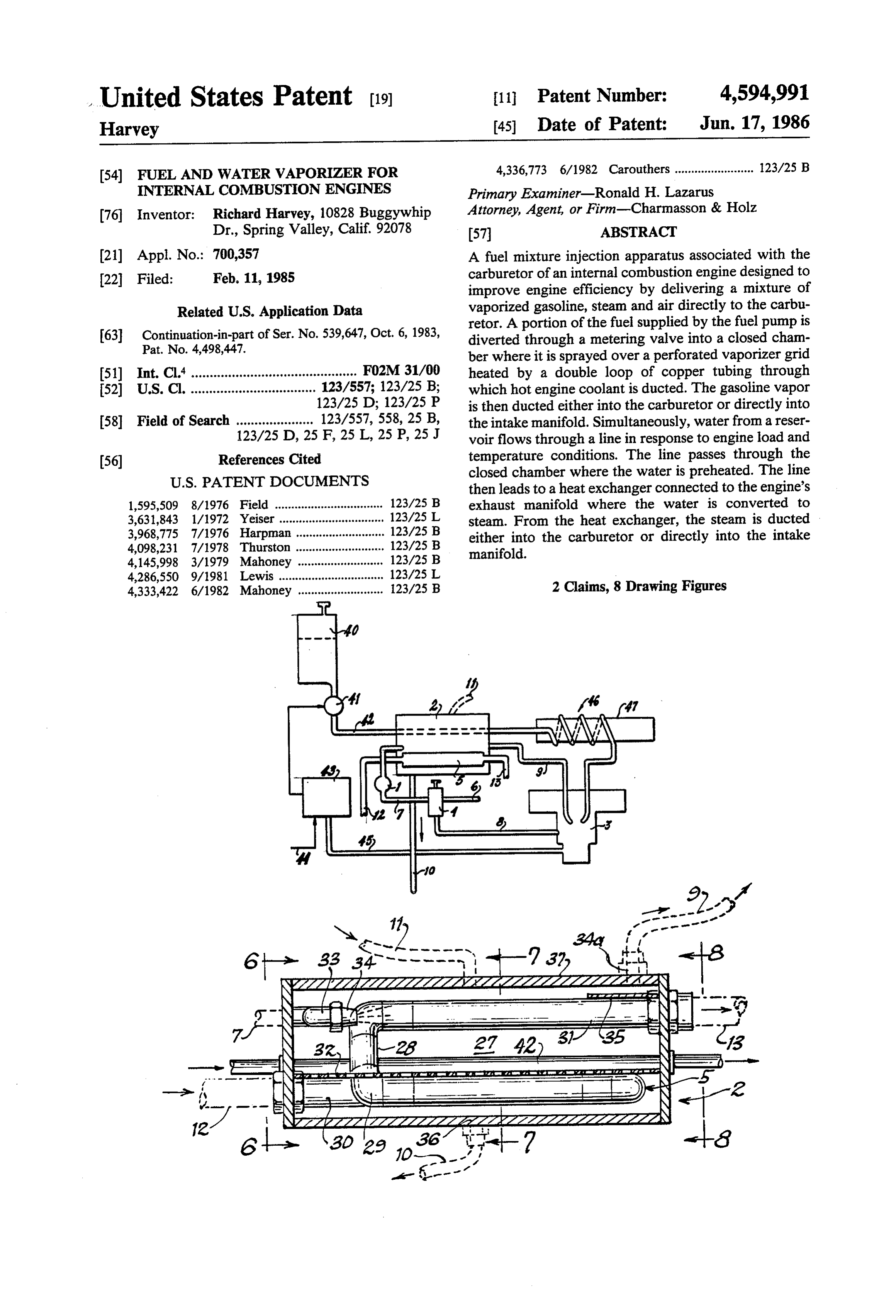
United States Patent (19) 11 Patent Number: 4,594,991 Harvey 45 Date of Patent: Jun. 17, 1986 (54) FUEL AND WATER WAPORIZER FOR 4,336,773 6/1982 Carouthers ........................ 123/25 B INTERNAL COMBUSTON ENGINES Primary Examiner-Ronald H. Lazarus (76. Inventor: Richard Harvey, 10828 Buggywhip Attorney, Agent, or Firm-Charmasson & Holz Dr., Spring Valley, Calif. 92078 57 ABSTRACT (21) Appl. No.: 700,357 A fuel mixture injection apparatus associated with the 22 Filed: Feb. 11, 1985 carburetor of an internal combustion engine designed to improve engine efficiency by delivering a mixture of
Related U.S. Application Data vaporized gasoline, steam and air directly to the carbu retor. A portion of the fuel supplied by the fuel pump is 63 Continuation-in-part of Ser. No. 539,647, Oct. 6, 1983, diverted through a metering valve into a closed cham Pat. No. 4,498,447. ber where it is sprayed over a perforated vaporizer grid (51) Int. Cl.' ............................................. FO2M 31/00 heated by a double loop of copper tubing through (52) U.S. C. .................................. 123/557; 123/25 B; which hot engine coolant is ducted. The gasoline vapor 123/25 D; 123/25 P is then ducted either into the carburetor or directly into 58 Field of Search ..................... 123/557, 558, 25 B, the intake manifold. Simultaneously, water from a reser 123/25 D, 25 F, 25 L, 25 P, 25 J voir flows through a line in response to engine load and (56) References Cited temperature conditions. The line passes through the
then leads to a heat exchanger connected to the engine's 1,595,509 8/1976 Field ................................. 123/25 B exhaust manifold where the water is converted to 3,631,843 1/1972 Yeiser ................................ 123/2.5 L steam. From the heat exchanger, the steam is ducted 3,968,775 7/1976 Harpman ........................... 123/25 B either into the carburetor or directly into the intake 4,098,231 7/1978 Thurston ........................... 123/25 B manifold.
4,286,550 9/1981 Lewis ................................ 123/2.5 L 4,333,422 6/1982 Mahoney .......................... 123/25 B 2 Claims, 8 Drawing Figures
Page 2
Drawing sheet — no readable text.
Page 3
Drawing sheet — no readable text.
Page 4
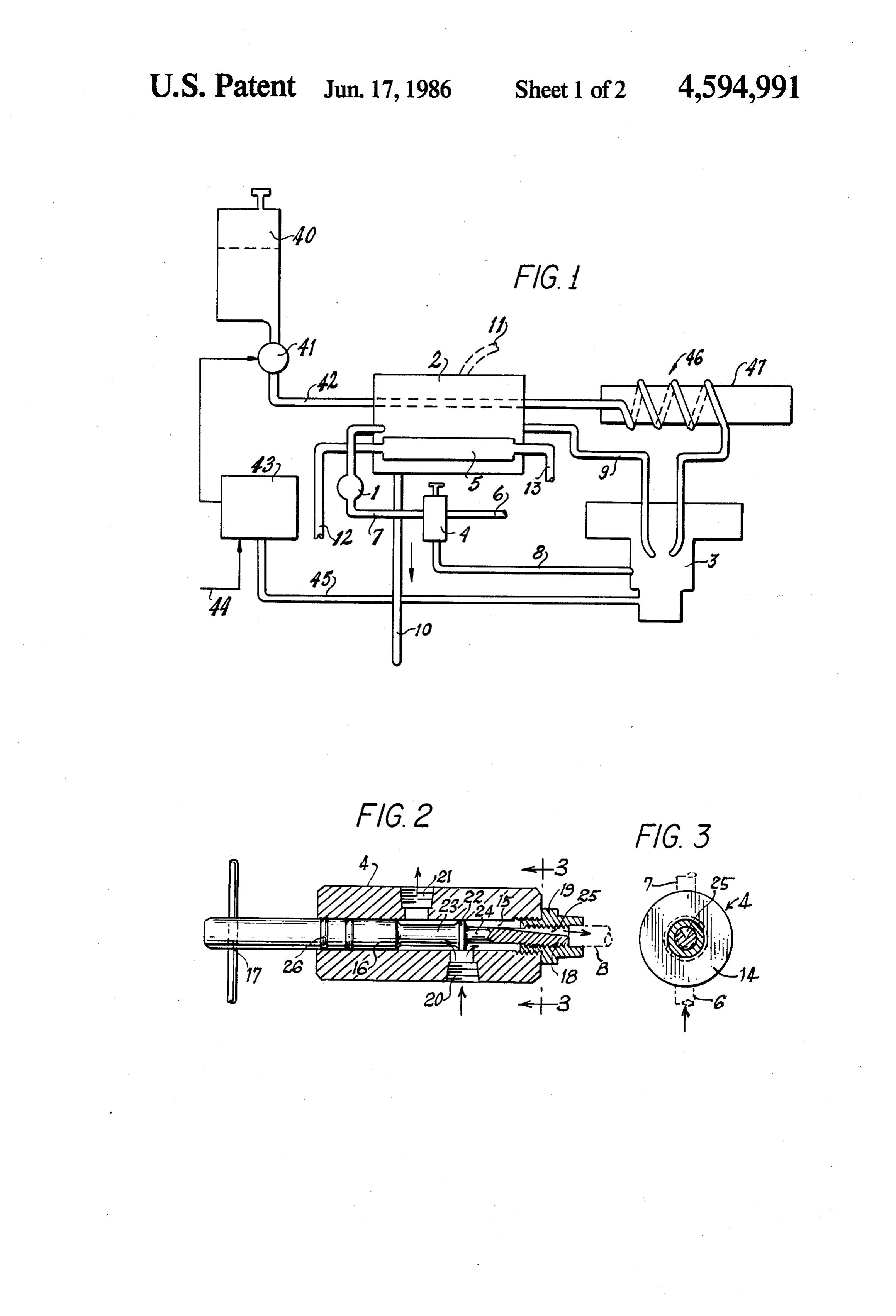
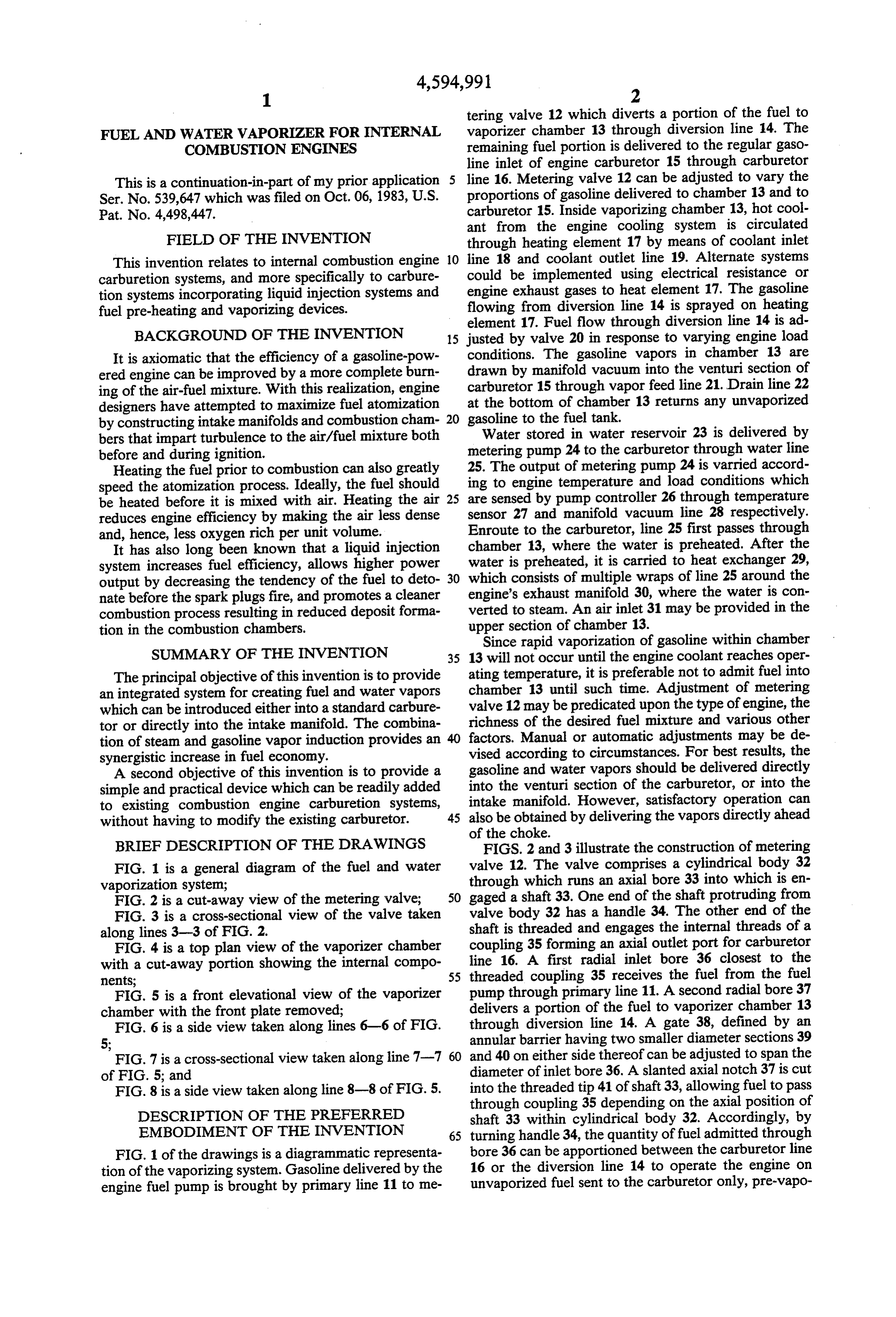
tering valve 12 which diverts a portion of the fuel to
FUEL AND WATER WAPORIZER FOR INTERNAL vaporizer chamber 13 through diversion line 14. The COMBUSTION ENGINES remaining fuel portion is delivered to the regular gaso line inlet of engine carburetor 15 through carburetor
This is a continuation-in-part of my prior application line 16. Metering valve 12 can be adjusted to vary the Ser. No. 539,647 which was filed on Oct. 06, 1983, U.S. proportions of gasoline delivered to chamber 13 and to Pat. No. 4,498,447. carburetor 15. Inside vaporizing chamber 13, hot cool ant from the engine cooling system is circulated
FIELD OF THE INVENTION through heating element 17 by means of coolant inlet This invention relates to internal combustion engine 10 line 18 and coolant outlet line 19. Alternate systems carburetion systems, and more specifically to carbure could be implemented using electrical resistance or tion systems incorporating liquid injection systems and engine exhaust gases to heat element 17. The gasoline fuel pre-heating and vaporizing devices. flowing from diversion line 14 is sprayed on heating element 17. Fuel flow through diversion line 14 is ad
BACKGROUND OF THE INVENTION 15 justed by valve 20 in response to varying engine load It is axiomatic that the efficiency of a gasoline-pow conditions. The gasoline vapors in chamber 13 are ered engine can be improved by a more complete burn drawn by manifold vacuum into the venturi section of ing of the air-fuel mixture. With this realization, engine carburetor 15 through vapor feed line 21. Drain line 22 designers have attempted to maximize fuel atomization at the bottom of chamber 13 returns any unvaporized by constructing intake manifolds and combustion cham 20 gasoline to the fuel tank.
bers that impart turbulence to the air/fuel mixture both Water stored in water reservoir 23 is delivered by before and during ignition. metering pump 24 to the carburetor through water line Heating the fuel prior to combustion can also greatly 25. The output of metering pump 24 is varried accord speed the atomization process. Ideally, the fuel should ing to engine temperature and load conditions which be heated before it is mixed with air. Heating the air 25 are sensed by pump controller 26 through temperature reduces engine efficiency by making the air less dense sensor 27 and manifold vacuum line 28 respectively. and, hence, less oxygen rich per unit volume. Enroute to the carburetor, line 25 first passes through It has also long been known that a liquid injection chamber 13, where the water is preheated. After the system increases fuel efficiency, allows higher power water is preheated, it is carried to heat exchanger 29, output by decreasing the tendency of the fuel to deto 30 which consists of multiple wraps of line 25 around the nate before the spark plugs fire, and promotes a cleaner engine's exhaust manifold 30, where the water is con combustion process resulting in reduced deposit forma verted to steam. An air inlet 31 may be provided in the tion in the combustion chambers. upper section of chamber 13. Since rapid vaporization of gasoline within chamber
SUMMARY OF THE INVENTION 35 13 will not occur until the engine coolant reaches oper The principal objective of this invention is to provide ating temperature, it is preferable not to admit fuel into an integrated system for creating fuel and water vapors chamber 13 until such time. Adjustment of metering which can be introduced either into a standard carbure valve 12 may be predicated upon the type of engine, the tor or directly into the intake manifold. The combina richness of the desired fuel mixture and various other tion of steam and gasoline vapor induction provides an factors. Manual or automatic adjustments may be de synergistic increase in fuel economy. vised according to circumstances. For best results, the A second objective of this invention is to provide a gasoline and water vapors should be delivered directly simple and practical device which can be readily added into the venturi section of the carburetor, or into the to existing combustion engine carburetion systems, intake manifold. However, satisfactory operation can without having to modify the existing carburetor. 45 also be obtained by delivering the vapors directly ahead of the choke.
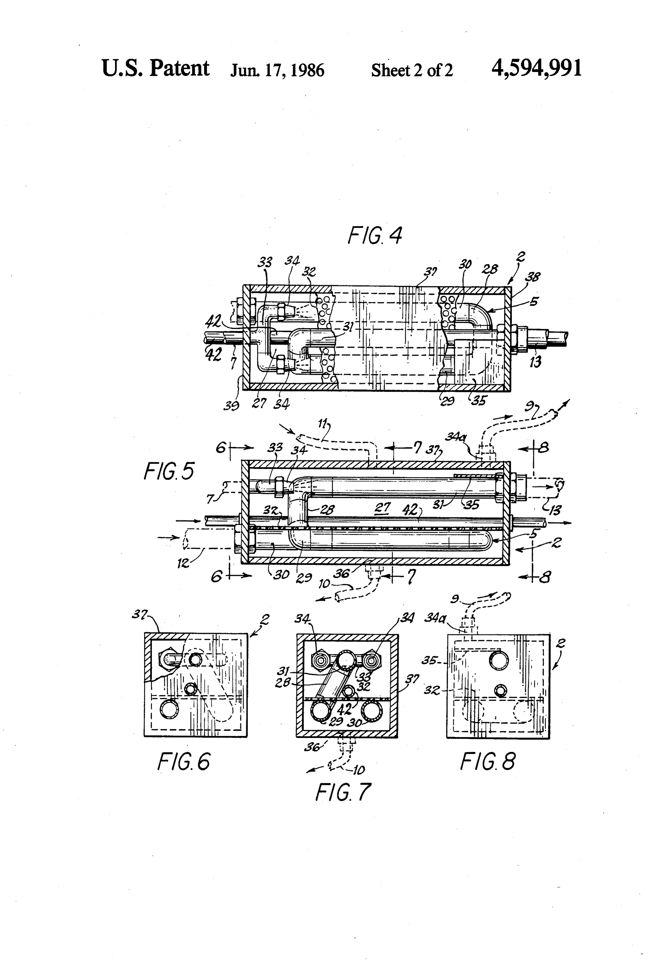
BRIEF DESCRIPTION OF THE DRAWINGS FIGS. 2 and 3 illustrate the construction of metering FIG. 1 is a general diagram of the fuel and water valve 12. The valve comprises a cylindrical body 32 vaporization system; through which runs an axial bore 33 into which is en FIG. 2 is a cut-away view of the metering valve; 50 gaged a shaft 33. One end of the shaft protruding from FIG. 3 is a cross-sectional view of the valve taken valve body 32 has a handle 34. The other end of the along lines 3-3 of FIG. 2. shaft is threaded and engages the internal threads of a FIG. 4 is a top plan view of the vaporizer chamber coupling 35 forming an axial outlet port for carburetor with a cut-away portion showing the internal compo line 16. A first radial inlet bore 36 closest to the nents; 55 threaded coupling 35 receives the fuel from the fuel FIG. 5 is a front elevational view of the vaporizer pump through primary line 11. A second radial bore 37 chamber with the front plate removed; delivers a portion of the fuel to vaporizer chamber 13 FIG. 6 is a side view taken along lines 6-6 of FIG. through diversion line 14. A gate 38, defined by an 5; annular barrier having two smaller diameter sections 39 and 40 on either side thereof can be adjusted to span the
FIG. 7 is a cross-sectional view taken along line 7-7 60 diameter of FIG. 5; and of inlet bore 36. A slanted axial notch 37 is cut FIG. 8 is a side view taken along line 8-8 of FIG. 5. into the threaded tip 41 of shaft 33, allowing fuel to pass through coupling 35 depending on the axial position of
DESCRIPTION OF THE PREFERRED shaft 33 within cylindrical body 32. Accordingly, by EMBODIMENT OF THE INVENTION 65 turning handle 34, the quantity of fuel admitted through FIG. 1 of the drawings is a diagrammatic representa bore 36 can be apportioned between the carburetor line tion of the vaporizing system. Gasoline delivered by the 16 or the diversion line 14 to operate the engine on engine fuel pump is brought by primary line 11 to me unvaporized fuel sent to the carburetor only, pre-vapo
Page 5
rized fuel only, or a combination of both. O-rings 42 heated means for vaporizing fuel comprising: near the outer end of shaft 33 prevent any leakage of a closed chamber having a fuel inlet, a vapor outlet, fuel. The notched threaded tip 41 provides for a fine a perforated septum lying horizontally across the adjustment of the fuel flow toward the carburetor. lower half of said chamber; FIGS. 4 through 8 illustrate the detail of hermetical- 5 a pipe passing through said chamber through ly-sealed rectangular-shaped vaporizer chamber 13. which hot fluid derived from the engine cooling Heating element 17 comprises a copper pipe 43 which system is circulated; and connects to line 18 in the lower part of chamber 13 at means associated with said inlet for spraying fuel one end thereof, and to line 19 in the upper part of against said septum;
chamber 13 at the other end. Copper pipe 43 is doubled 10 means for generating steam in proportion to the mani back upon itself twice in order to span the length of the fold vacuum created by the engine, wherein said chamber three times. Two sections 44 and 45 are in the means for generating steam comprises: same horizontal plane close to the bottom of chamber a supply of water;
3. An upper section 46 stretches across the upper me a variable output water pump; dian part of the chamber, and connects to line 19. A grid 15 means for controlling the output of said water 47 forms a perforated septum in contact with the lower pump in response to the intake manifold vacuum sections 44 and 45. A T-coupling 48 connected to line generated by the engine; and 14 leads to a pair of nozzles 49 directed horizontally a heat exchanger to apply heat from the engine's across the areas of grid 47 contiguous to pipe sections 44 exhaust manifold to the water delivered by said and 45. Vapor outlet 50, to which is connected line 21, 20 water pump, said heat exchanger having a con is located in the roof of chamber 13. A shield plate 51, duit leading from said water pump to said carbu located a short distance immediately below outlet 50, retor; and said conduit passing through said prevents the introduction of unvaporized gasoline into heated means and subsequently being intimately line 21. Optional air inlet line 31 enters chamber 13 wrapped around a portion of the exhaust mani through the median section of the chamber roof. 25 fold of said engine;
Grid 47 is designed to provide a broad heating ele means for delivering a portion of the fuel supply ment against which the gasoline may be sprayed. Gaso through said heated means, comprising: line which fails to vaporize collects at the bottom of a metering valve having an inlet port and first and chamber 13 and is returned to the fuel tank through line second outlet ports;
22. The upper section 46 of copper pipe 43 is designed 30 an adjustable gate controlling the distribution of fuel to maintain a high temperature in the upper part of the admitted through said inlet between said outlet chamber and thus expedite and maintain the vaporiza ports;
tion process. Air inlet line 31 may be brought to a con ducting means connecting said inlet port to a pressur venient place within the engine compartment or outside ized fuel supply, said first outlet port to the fuel it and may be fitted with a filtering mesh to prevent 35 inlet of the carburetor and said second outlet port intake of dust and debris. to the fuel inlet of said chamber; and In this preferred embodiment, chamber 13 is made conduit means for delivering steam from said means from a rectangular extrusion section 52 closed at both for generating and vapor from said means for va ends by end plates 53 and 54 which are maintained in porizing into said carburetor. place by couplings between heating pipe 43 and coolant 40 2. The apparatus of claim wherein said metering lines 18 and 19. Water line 25 passes through end plates valve comprises:
53 and 54 on its way through the upper part of chamber a cylindrical body having an axial bore and first and 3, where it is in contact throughout the length of said second radial bores axially spaced apart; chamber with grid 47. a shaft engaged into the axial bore from one end of In certain applications, the carburetor could be com 45 said cylindrical body;
pletely omitted and the engine operated only on the a part of said shaft protruding from said one end and vapors generated by vaporizer unit. having means for rotating the shaft; While the preferred embodiment of the invention has an internally-threaded coupling forming said first been described, other embodiment may be devised and outlet port engaged into said axial bore at the other modifications may be made thereto without departing 50 end of said cylindrical body; from the spirit of the invention and the scope of the the tip of said shaft having a radial notch and threads appended claims. engaging said threaded coupling; and What is claimed is: said gate comprises an annular barrier on said shaft, 1. In combination with a gasoline-powered internal said barrier having adjustable axial positions span combustion engine, and fuel supply, an apparatus for 55 ning the diameters of the radial bore closest to said injecting a fuel mixture of vaporized fuel, fuel, steam threaded coupling.
and air into the engine carburetor which comprises: ar is
Provenance
- Collection
- Cited prior art
- Original PDF
- patentimages.storage.googleapis.com →
- Filed
- 1985-02-11
- Pages
- 5
- Method
- pdftotext (the PDF's own text layer) + pdftoppm 300dpi page scans
- Source
- Google Patents bibliographic record
- Granted
- 1986-06-17
- Inventors
- Richard Harvey
- Transcribed from
- patentimages.storage.googleapis.com →