patent · US5087344
Electrolysis cell for gas-evolving electrolytic processes
11 February 1992
Page 1 — bibliographic record
HHHHHHHHH
United States Patent (19) 11 Patent Number: 5,087,344 Wenske et al. (45) Date of Patent: Feb. 11, 1992 54 ELECTROLYSIS CELL FOR GAS-EVOLVING 4,194,961 3/1980 Williams ......................... 204/270 X ELECTROLYTIC PROCESSES 4,379,742 4/1983 Rathgen ... ... 204/286 4,389,298 6/1983 Pellegri..... ... 204/288 75) Inventors: Hanno Wenske; Arnold Gallien, both 4,422,919 12/1983 Fabian ................................. 204/270 of Grimma; Wolfgang Hanke, 4,457,816 7/1984 Galluzzo et al ... 204/270 X Leisnig-Tragnitz; Wolfgang Lampe, 4,557,818 12/1985 Roos .................................... 204/288 Grimma; Lothar Illgen, Dresden, all 4,695,355 9/1987 Koziol ....... ... 204/252 of Fed. Rep. of Germany 4,747,925 5/1988 Hasebe et al. ....................... 204/270 73 Assignee: Heraeus Elektroden GmbH, Hanau, Primary Examiner-Donald R. Valentine Fed. Rep. of Germany Attorney, Agent, or Firm-Frishauf, Holtz, Goodman & Woodward
An electrolysis cell for gas-evolving electrolytic pro 51) Int. Cl. ....................... C25B 9/00; C25B 11/02; cesses using at least one electrode having electrode C25B 11/03; C25B 15/08 elements arranged parallel is described; the electrode 52) U.S. Cl. .................................... 204/256; 204/258; elements have a thickness of up to three times the mean 204/266; 204/270; 204/272; 204/283; 204/284 bubble separation diameter and have a capillary gap
204/263-266, 283, 272 with respect to one another such that a motion of the gas bubbles through the electrode is brought about 56) References Cited substantially in the direction or in the opposite direction
anode and cathode.
3, 13,918 2/1963 Evans .............................. 204/270 X 3,835,209 9/1974 Galneder . ... 204/27O X 4,022,679 5/1977 Koziol ................................. 204/219 16 Claims, 6 Drawing Sheets
Page 2
Drawing sheet — no readable text.
Page 3
Drawing sheet — no readable text.
Page 4
Drawing sheet — no readable text.
Page 5
Drawing sheet — no readable text.
Page 6
Drawing sheet — no readable text.
Page 7
Drawing sheet — no readable text.
Page 8
Two important basic types of gas-evolving metal
ELECTROLYSIS CELL FOR GAS-EVOLVING electrodes are known: On the one hand, profiled paral ELECTROLYTIC PROCESSES lel bars which are circular, elliptical, teardrop-shaped, or rectangular in cross section and are supported by
Cross-reference to related U.S. patents and applica current distributors are used (West German Patent Dis tions, the disclosures of which are hereby incorporated closure Documents DE-OS 30 08 116 and 33 25 187; by reference: West German Patent 3519 272; and West German Pa U.S. Pat. No. 4,422,919, FABIAN et al./HERAEUS, tent Disclosure Document DE-OS 35 19573). U issued Dec. 27, 1983; shaped, spaced-apart aligned rails, however, are also U.S. Ser. No. 755,324, FABIAN et al., filed June 24, 10 known, from West German Examined Patent Applica 1985, now abandoned, and its continuation, tion DEAS 1271 093.
U.S. Ser. No. 873,115, FABIAN et al., filed June 10, On the other hand, perforated metal sheets with slits 1986, now abandoned, both corresponding to that extend vertically and horizontally, with segments PCT/EP 84/00335; that are deepdrawn or angled relative to the electrode 15 plane, perforated metal sheet electrodes, and expanded
U.S. Pat. No. 4,022,679; metal mesh electrodes, are also known (East German U.S. Pat. No. 4,389,298; Patent 250 026, and West German Patent Disclosure U.S. Pat. No. 4,557,818, ROOS et al./BASF AG, Documents DE-OS 36 25506 and 27 35238). issued Dec. 12, 1985; Examples of the first basic type use parallel electrode U.S. Pat. No. 4,695,355, KOZIOL/CONRADTY 20 elements, which are firmly connected to current distrib GmbH, issued Sept. 22, 1985; issued Apr. 12, 1983. utor rails and have a teardrop-shaped cross section Cross-reference to related foreign patent documents: (DE-OS 33 25 187) or an approximately circular cross GB 2,180,556, SHIMAMUNE/PERMELEC section (DE-OS 30 08 116). The circular cross section ELECTRODE LTD, July 19, 1989, correspond was modified by cutting off segments that are located in ing to German DE-OS 36 25506, publ. Feb. 5, 25 the electrode plane. Both electrodes are intended pref 1987; erentially for use in chlor-alkali electrolysis in amalgam West German DE-AS 1271 093; cells. These electrodes have no substantially reduced East German Patent 250 026; degree of coverage of gas bubbles. The removal of the West German DE-OS 27 35,238. gas is effected solely by the fluid flow and by buoyancy. The invention relates to an electrolysis cell for gase volving electrolytic processes which is particularly 30 The particular crosssectional geometries are not suit able to take on an active role in gas transport through suitable for use in water and chlor-alkali electrolysis. the electrode. Although by avoiding irregularities they For the production of various important basic chemi prevent an overload on the catalytic coating, neverthe cal materials, such as caustic soda, chlorine, hydrogen less this is done at the cost of the disadvantages of the or hydrogen peroxide, gas-evolving electrolytic pro 35 uneven spacing of the electrode faces, dictated by the cesses are of outstanding importance. The electrodes, radius.
both anodes and cathodes, to be used in the electrolysis DE-OS 35 19272 discloses an electrode structure that of alkaline solutions, water, and hydrochloric or sulfu has a plurality of parallel electrode elements of rectan ric acid must meet a number of sometimes contradictory gular cross section. A plate-like support with indenta usage parameters. One very essential requirement is the tions on both sides secures the electrode elements and rapid removal of the evolved gas from the space be serves as a current distributor. The cross section of the tween the anode and the cathode, in order to avoid a rectangular electrode elements is intended to have a large gas proportion that increases the electrical resis ratio of 1:5. To prevent the gas removal lugs in the tance of the electrolyte. However, this conflicts with vicinity of the gap from coming into contact with one the attempt to make maximum use of the available struc 45 another and causing turbulence, a relatively large gap tural surface area for an electrochemically active elec between adjacent electrode elements is provided. This trode surface. results in relatively low utilization of the available The attempt is also made to have the electrode sur structural surface area and causes an uneven electrode face be as uniform and finely structured as possible, to load, particularly in the vicinity of the edges of the meet the prerequisites for a homogenous electrical field. 50 rectangular profiles, where increased wear of the cata Discontinuities, such as edges, cause increases in field lytic coating must be expected. The selected shape of intensity and thus cause an uneven electrode load, re the support for the electrode elements, which at the sulting not only in energy losses but also in premature same time is a current distributor, prevents the concen wear of the electrode material or electrocatalytic coat tration of the gas in the space on the other side of the ling. 55 reactive electrode face. The result is a high gas propor To separate the gases formed at the electrodes, mem tion in the region of the reaction face, associated with branes or diaphragms are used. These separating ele increased electrical losses.
ments have a relatively high ohmic resistance, so that The electrode disclosed in DE-OS 35 19573 is quite the gas separation is achieved at the cost of high energy similar to the electrode structure described above. It expense. likewise comprises electrode elements of rectangular Another essential factor to assure an optimal process cross section, disposed parallel on a current distributor is to achieve a uniform, small electrode spacing, without and spaced apart from one another by several millime putting major mechanical strain on membranes, if used, ters. The face ends of the electrode elements oriented or even damaging them. Electrode elements of great toward the membrane also have a number of recesses. thickness should also avoid exerting high contact pres 65 The webs located between them are not electrocatalyti sure upon the membrane, which would notably hinder cally coated and rest on the membrane. The available the electrolyte flow or ion transport through the pore reactive surface area is thus only about 10% of the system of the membrane. membrane surface area. Because of relative motions
Page 9
between the electrode and the membrane, the webs may are blades, strips or foils with a maximum thickness of cause local damage to the membrane. 450 um. The width of the electrode elements is substan The object of the invention is to develop an electroly tially greater than their thickness and is at least 10 times sis cell for gas-evolving electrolytic processes having the width of the capillary gap. As a result, a capillary substantially altered performance parameters. It should system that acts two-dimensionally is created in the enable a significant reduction in the ohmic power losses electrode, which prevents the introduction of turbu and thus an increase in the specific electrical load on the lence from the degassing chamber of the electrolyte into electrodes; nevertheless, however, the degree of gas the reaction chamber between the electrode and the enrichment at the electrode faces is intended to be re membrane. This precludes influence on or disturbance duced considerably, despite the increased gas produc 10 of the bubble forming process and bubble transport into tion. Specifically, the following objects are to be at the capillary gap. The gas transport through the elec tained: trode takes place in aligned fashion, substantially trans Reducing the burden of gas bubbles in the electrolyte versely to the electrode plane, across the very short between the electrodes and the degree of coverage path corresponding to the width of the electrode ele of gas bubbles on the reaction faces of the elec 15 ments. The reason for this is the considerable relative trode; increase in volume in the reaction chamber because of the electrode structure is intended to assure an the bubble forming process. This causes a pressure in aligned gas transport during the process; crease and a positive displacement reaction there. To improvement of the ratio of active electrode surface the same extent as the gas is positively displaced out of area to structural surface area; 20 the reaction chamber and the electrode, electrolyte lessening the increase in local field intensity and de flows without turbulence through the capillary gap to velopment of an approximately homogenous elec the reactive surfaces of the electrode. The high degree trical field, to make the load on the electrode sur of electrolyte exchange prevents ionic depletion of the face area available for reaction more uniform. electrolyte, even in its boundary layer, since because of The novel electrolysis cell is intended to have gas 25 the capillary forces, the liquid transport takes place separating properties, thus making it unnecessary directly at the electrode surface. The characteristic to use gasseparating means (such as membranes, flow conditions in the capillary gap prevent vertical diaphragms or the like). motion of the gas bubbles to the maximum possible The electrode spacing should not be increased. extent.
According to the invention, this object is attained by To achieve the principle of the electrolysis cell ac an electrolysis cell for gas-evolving electrolytic pro cording to the invention, two variant electrodes prove cesses, in particular for water and chlor-alkali electroly to be particularly advantageous. Folding endless mate sis, having at least one electrode comprising electrode rial of large surface area on alternate sides enables eco elements arranged parallel and forming an anode and nomical production of capillary gap electrodes; all the cathode, by providing that the electrode elements have 35 necessary operations such as perforations, profiling and a thickness of only up to three times the mean bubble coating are suitably performed beforehand in a continu separation diameter and that they have a capillary gap ous process. These perforations in the region of the with respect to one another such that the direction of folded edges are suitably distributed uniformly. For motion of the gas bubbles through the electrode is sub defining the capillary gap, the electrode elements have stantially in the direction and in the opposite direction 40 profiled sections. Those that have a web-like structure of the electrical field between the reaction surfaces of extending transversely to the electrode plane have the anode and cathode. The invention is intended to proven themselves; knob-like or button-like profiled encompass electrolysis cells that are made up of elec sections have also proved to be useful. Stacking of elec trode structures with quasi-parallel electrode elements trode elements profiles in accordance with the inven forming a capillary gap, as is the case for instance for a 45 tion is also suitable for producing capillary gap elec spirally wound electrode, as well. trodes. The profiled sections generated in the initial The bubble separation diameter is the diameter of a forming process or by subsequent deformation define bubble, as it leaves its nucleus, under existing actual the capillary gap and make separate spacers unneces process conditions at an electrode of the type according sary.
to the invention. By definition, a bubble leaving its 50 The lower limit to the thickness of the electrode nucleus is also one that moves by adhesion on the elec elements is determined solely by processability, me trode surface. chanical stability and manipulability of the material, or The separation diameter of gas bubbles is known to in other words in the final analysis by the type of mate depend to a considerable extent on the type of electroly rial.
sis and on the process conditions. According to the 55 In order to enable full exploitation of the advanta journal Elektrochimika Acta, Vol. 33, No. 6, pp. geous of the novel electrolysis cell, it is advantageous to 769-779, 1988, the following bubble diameters can be seal off both the electrode elements that laterally define expected under typical electrolysis conditions: the electrode and the lower closure of the electrode For hydrogen: approximately 8 um toward the inner wall of the cell housing, except for a For oxygen: approximately 17 um 60 gap that at most is equivalent to the capillary gap. The For chlorine: approximately 110 um degassing chambers in the upper cell region are also An electrolysis cell according to the present inven closed off in gas-tight fashion by a bulkhead, which tion assures that the capillary action of the electrode, extends at least as far as the lowest possible level of the beginning at the region between the electrode elements, liquid electrolyte in the reaction chamber. This pre also affects the bubbles formed on the mostly rounded 65 vents mixing of the gases that rise in the degassing end faces, and aspirates them into the capillary gap even chambers of the electrolysis cell. if some spacing has been left between the electrode and When this kind of cell construction is used for water the membrane. Advantageously, the electrode elements electrolysis, in other words a process that does not

Page 10
require separation of the anolyte and catholyte, the use 10:1) made of a foil-like material folded on alternate of a gas separating system such as a diaphragm may be sides;
unnecessary, or may permit the use of a comparatively FIG. 9; an enlarged detail B of the capillary gap large-pored element, which optionally may merely fix electrode of FIG. 8:
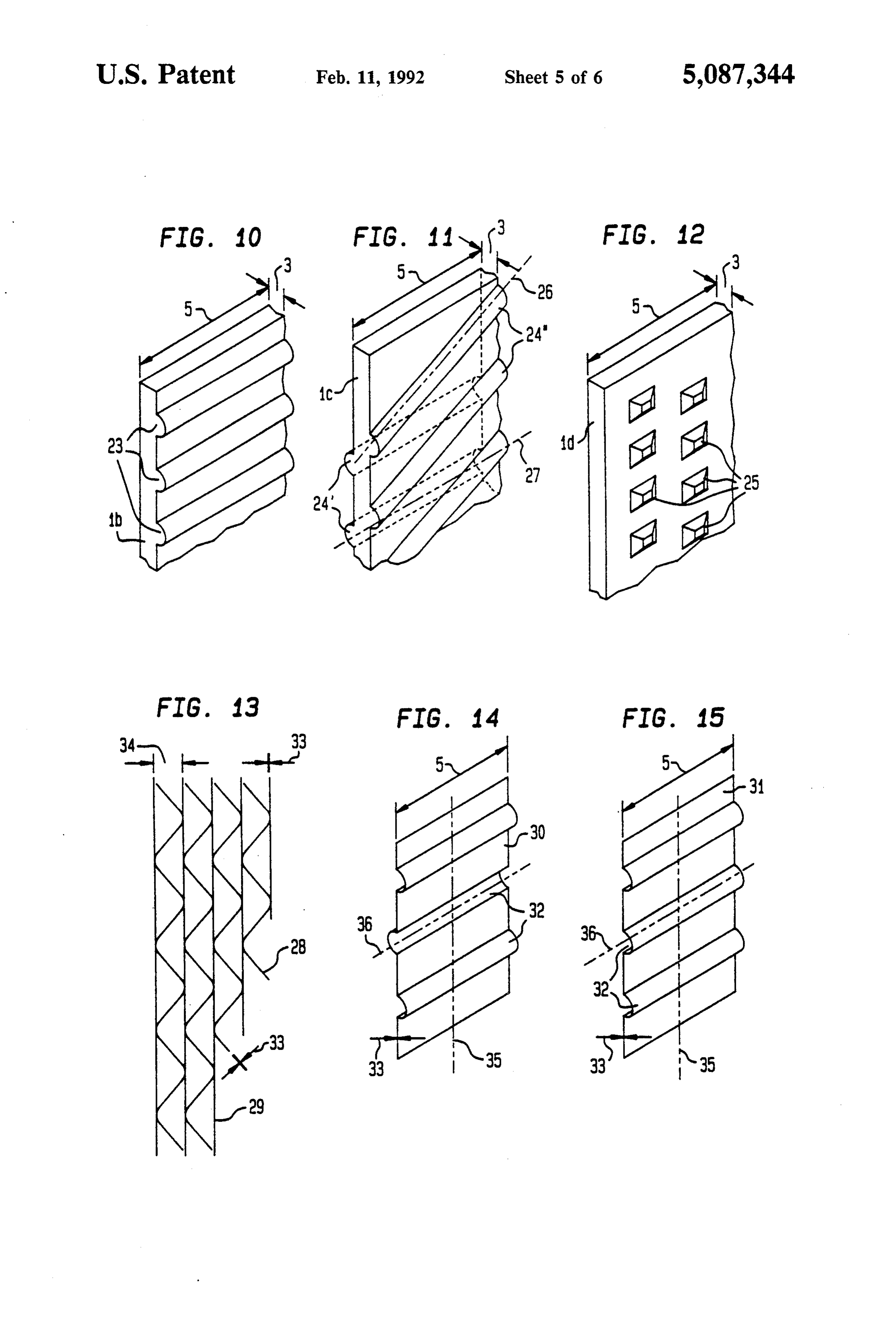
the electrode spacing, having a negligible Ohmic resis FIG. 10: an enlarged perspective view of an electrode tance. element with web-like profiled portions extending hori To prevent coagulation of gas bubbles that arise at zontally (on one side);
oppositely poled electrodes, a spacing that at least cor FIG.11: an enlarged perspective view of an electrode responds to three times the bubble separation diameter element with web-like profiled portions extending hori must be provided between the electrodes. This charac 10 zontally (on both sides);
teristic counteracts contamination of the gas bubbles FIG.12: an enlarged perspective view of an electrode rising in the degassing chambers and also counteracts element with local profiled portions (knob-like, of arbi the formation of mixed-gas in the reaction chamber trary direction);
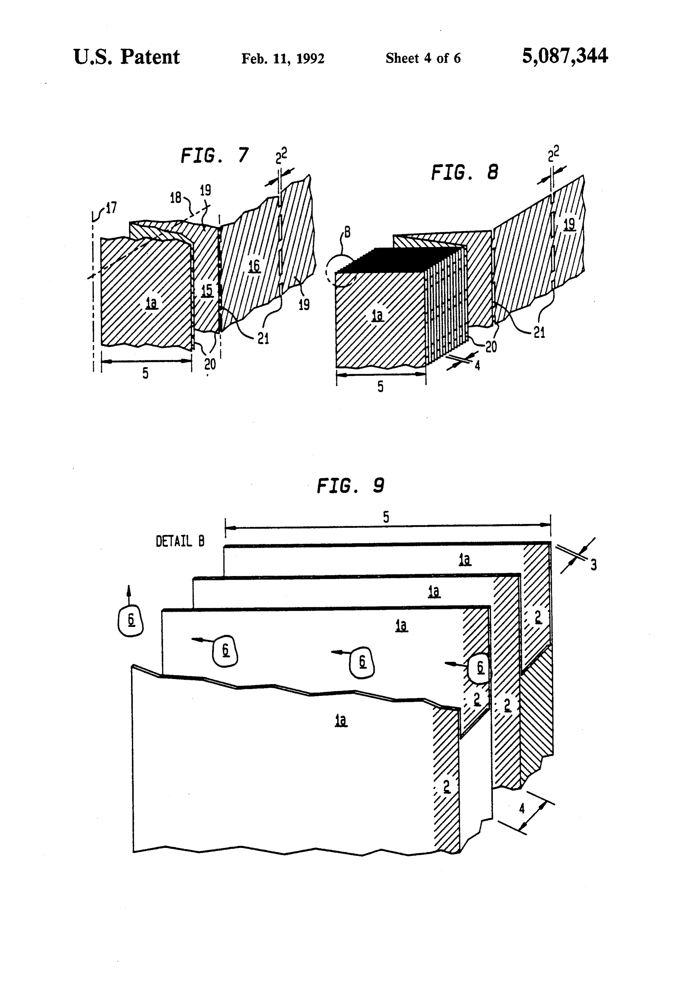
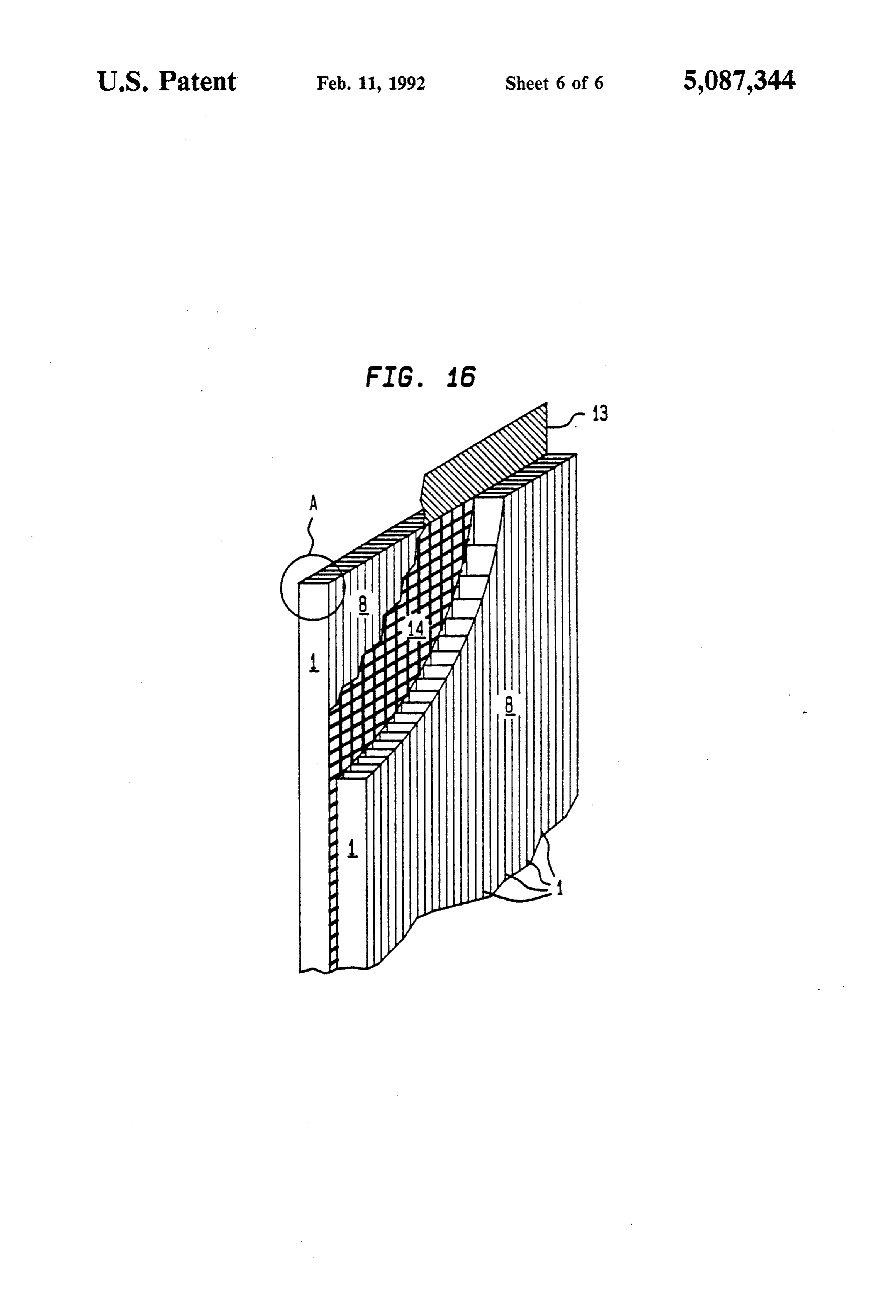
caused by coagulation of gas bubbles. FIG. 13: a detail of an electrode made of alternatingly An advantageous variant of the invention for use in 5 arranged corrugated and unprofiled electrode elements; water electrolysis, or in other words where the anolyte FIG. 14: an enlarged, perspective view of an elec and catholyte are identical, uses a dielectric electrolyte trode element with beads disposed on both sides; proof spacer element between the anode and cathode; FIG. 15: an enlarged, perspective view of an elec this element may in particular have the structure of a trode element with beads disposed on one side; and net, honeycomb, or wide-mesh woven fabric. In accor 20 FIG. 16: a perspective detail view of two capillary dance with its thickness, the spacer element assures the gap electrodes as the cathode and anode, with a spacer fixation of the anode and cathode with short spacing, element located between them (scale: approximately which is secure against short-circuiting. The great flexi 1:1).
bility of the electrode structure, which can withstand For the sake of clarity, FIGS. 2-16 show only the heavy mechanical loads, assures a uniform electrode 25 electrode elements, or the electrodes formed from spacing on all sides. Moreover the reaction chamber is them, which are used in an electrolysis cell. As can be divided by the spacer element into a plurality of small seen from FIGS. 1-8 and 16, the electrode is made up of reaction cells. Disturbances caused by the flow, and the electrode elements 1, 1a, 28, 29, disposed parallel or formation of mixed gas, can virtually no longer occur. quasi-parallel to one another, the thickness 3 and spac The advantages of the electrodes comprising elec 30 ing 4 of which relative to one another are smaller by trodes of elements according to the invention having a one to two orders of magnitude than in known elec capillary gap arrangement are as follows: trodes.
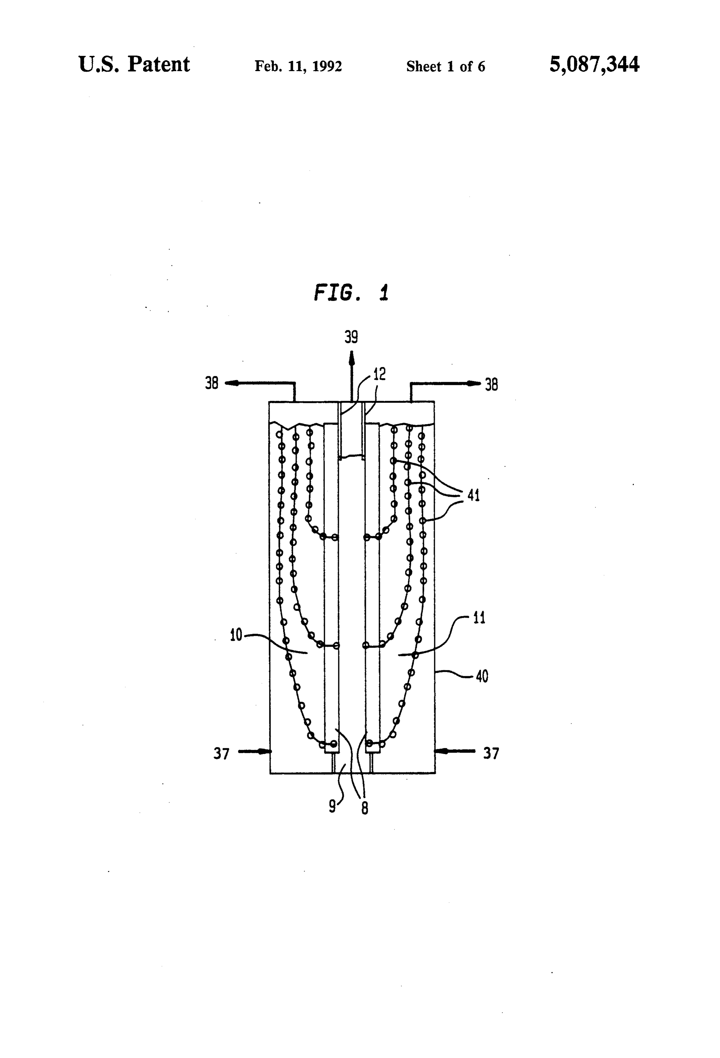
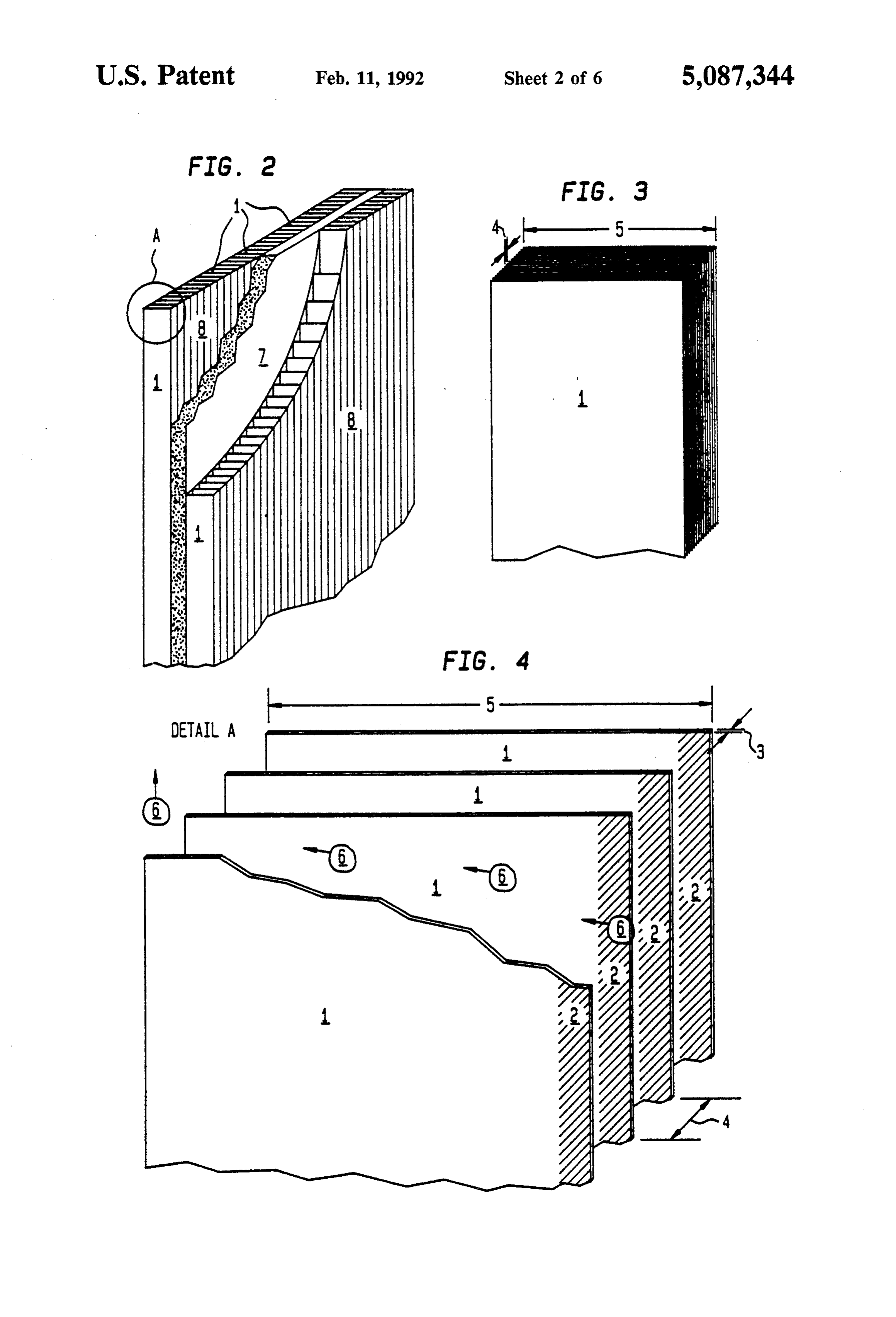
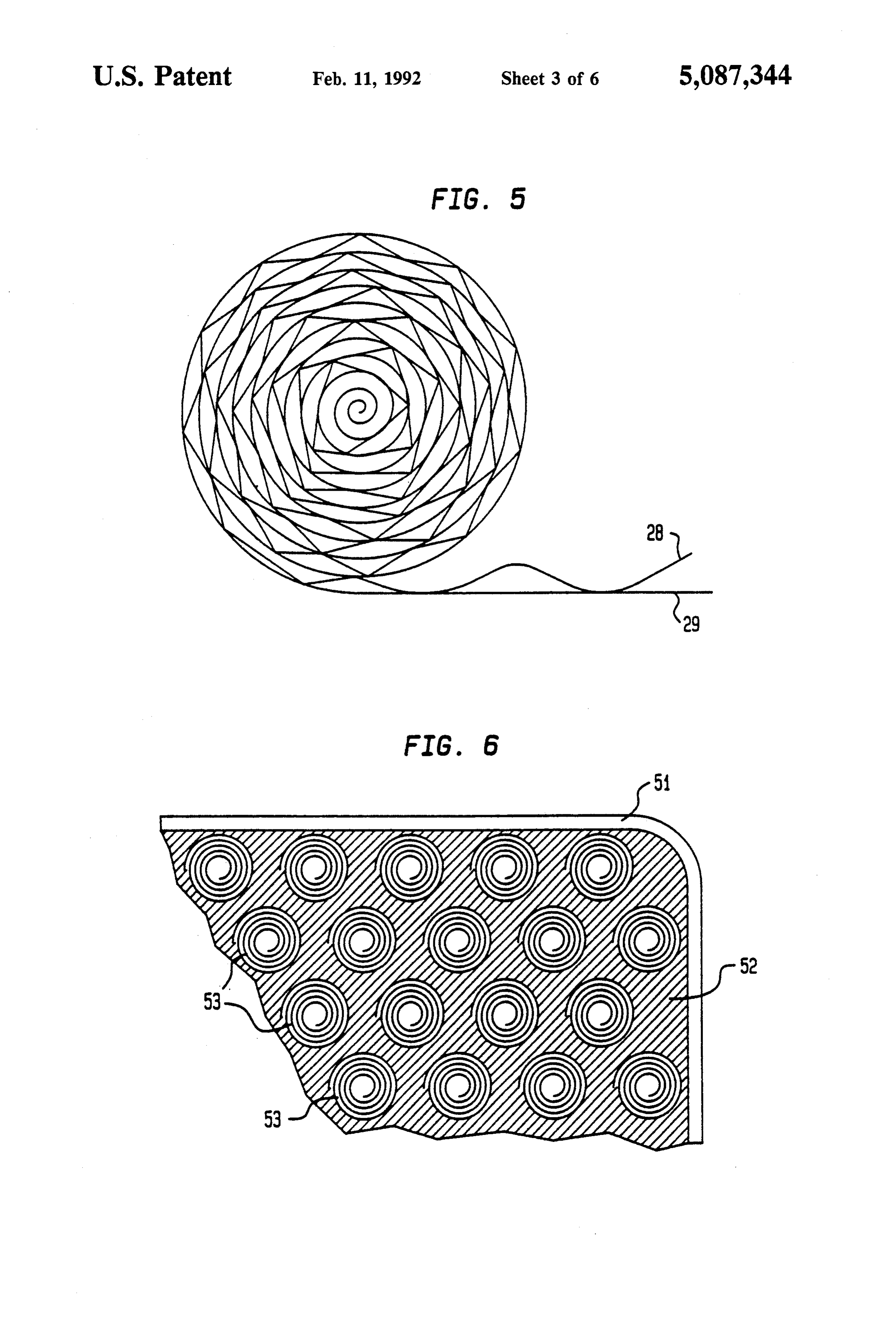
Very small gas bubble burden of the electrolyte in the According to the invention, the thickness 3 of the reaction chamber because of an aligned gas bubble electrode elements 1, 1a, 1b, 1c, 1d, 15, 16, 28, 29, 30, 31 transport within the capillary gap electrode; 35 shown in FIGS. 2-16, which may be strips, foils or an electrode structure of high packing density that is blades, is at most three times the mean bubble separation uniformly and finely structured and is permeable to diameter. A gap 4 that brings about the capillary effect gas and liquid is provided between the electrode elements 1, 1a, 1b, 1c, as a result: uniform current load and exploitation of 1d, 15, 16, 28, 29, 30, 31. The fixation of the electrode the available reaction surface area, no local erosion 40 elements to one another can be effected for instance by of the electrode surface, in particular of the electro a plurality of wires penetrating the electrode elements. catalytic coating; and Between the electrode elements, spacers may be dis mechanically loadable yet flexible and thus conform posed on the wires, to assure the capillary gap. The use ing electrode structure; no stringent requirements of profiled electrode elements 1a, 1b, 1c, 1d 15, 16, 28, in terms of flatness, rejection of defective elements, 45 29, 30, 31 is more advantageous. These provisions make and the like. it simple to furnish a transportable, mountable capillary Exemplary embodiments of the invention, and in gap electrode that is readily adaptable in width. particular of the electrode elements, will now be de The production of electrode elements from glass scribed in further detail, referring to the drawings. metal foil strips made by the melt spinning process is Shown are: 50 particularly economical. They have smooth surfaces FIG. 1: a cross section of an electrolysis cell accord and edges and typically have a thickness of from 20 m ing to the invention, with capillary gap electrodes; to 100m. The preferred range of the electrode element FIG. 2; a detailed perspective view of two capillary thickness is about 40 um; the width of the strips is ap gap electrodes as the cathode and anode, with a separat proximately 5 mm. Using approximately 40 electrode ing element between them; 55 elements percentimeter establishes a mean capillary gap FIG. 3: an enlarged detail A of FIG. 2 (scale: approx 4 that is 200 m in width. An electrode comprising a imately 10:1); plurality of intrinsically highly flexible individual ele FIG. 4: an enlarged detail A of FIG. 2 (scale: approx ments, in the form of a tight package, represents a struc imately 20:1); ture that is mechanically heavily loadable and neverthe FIG. 5: an electrode winding element, in a sectional less is fully conforming to a flat surface. These surfaces view; need not meet stringent requirements in terms of flat FIG. 6: a cross section of a capillary gap electrode ness, rejection and the like.
comprising a plurality of electrode winding elements; FIG. 2 shows two electrodes 8 comprising electrode FIG. 7: an enlarged perspective view of electrode elements 1, one of which forms the cathode and the elements having a corrugated structure (scale: approxi 65 other the anode, with a separating element 7 such as a mately 10:1); membrane between them, at a socalled zero spacing. FIG. 8: an enlarged perspective view of part of an The electrode structure allows a constant, small elec actual capillary gap electrode (scale: approximately trode spacing over a large surface area, this spacing
Page 11
being equivalent to the thickness of the separating ele the axis 26, do not extend parallel to the profiled por ment 7. The conformability of the electrode 8 further tions 24', having the axis 27, on the other side of the more assures uniform distribution of pressure over the same electrode element ic. This makes it possible to separating element 7, which not only prevents it from double the capillary gap between adjacent elements 1c. being damaged but also does not impair the ion or elec If electrode elements ic of the kind shown in FIG. 11 trolyte flow. The chambers that adjoin the electrode are stacked, the intersecting profiled portions 24', 24' faces that are remote from the separating element 7 have a point-type contact. However, it is also possible serve as degassing chambers for the electrolyte. to arrange electrode elements 1c that are profiled on FIGS. 3 and 4 show the detail A of the electrode 8 of both sides in alternation with smooth, unprofiled elec FIG. 1 on a larger scale. The electrode elements 1 used O trode elements.
have a thickness 3 of approximately 30 um and a width FIG. 12 shows knob-like profiled portions 25 of arbi 5 of approximately 5 mm. The capillary gap 4 between trary direction, on one side of the electrode element 1d. the electrode elements is approximately equivalent to However, it is also possible to provide profiled portions 200 um. The faces 2 of the electrode elements 1 (see 25 on both sides of the electrode element 1d. FIG. 4) represent the regions of high electrolytic reac 5 The profiled portions 23, 24", 24", 25 as shown in tivity. Their conversion per unit of surface area is ap FIGS. 10-12 can be produced by embossing tools. The proximately equivalent to that on the end faces of the production of electrode elements 1b, 1c, 1d by the melt electrode elements 1. These highly reactive faces 2 that spinning method to make glass-metal foil strips is espe substantially participate in the conversion extend trans cially economical. They usually have a thickness 3 of 20 versely to the electrode plane at a depth that is approxi 20 um to 100 m and can be made in the desired width. To mately equivalent to the width of the gap 4. For the make the profiled portions 23, 24, 24", 25, the surface of sake of greater clarity in the drawing, the width of the the roller is prepared accordingly. gap 4 has been exaggerated by a factor of 3 in compari FIG. 13 shows the cross section of a part of an elec son to the thickness and width of the electrode elements trode that comprises a package, with alternatingly ar 1. 25 ranged profile and unprofiled electrode elements 28, 29. FIG. 5 shows another variant of an identically func The profiled portions of the electrode elements 28 have tioning electrode structure with a capillary gap. Spi a corrugated structure, which results in a constantly rally winding a pair of electrode elements comprising varying capillary gap. Half the distance 34 between two one smooth electrode element 29 and one electrode adjacent, unprofiled electrode elements 29 can be con element 28 with a corrugated profile creates a quasi-par 30 sidered to be the mean capillary gap width. The use of allel electrode structure. The definition of the desired this package, because of the resilient action of the corru capillary gap may also be effected by electrode ele gated electrode elements 28, enables very simple varia ments profiled in some other way, which will be ex tion of the width of the capillary gap 4. Accordingly, plained hereinafter. electrodes for various electrolytic processes can be An electrode portion comprising a plurality of elec 35 made with one and the same kind of profiling. trode winding elements 53 is shown in FIG. 6. This FIGS. 14 and 15 show electrode elements 30, 31 with electrode is bounded by a current lead 51. The electrode beadlike profiled portions 32 on both sides and on one winding elements 53 are supported by a current distrib side, respectively, the axes 36 of which extend orthogo utor 52. Arbitrary, electrically adequately conductive nally to the longitudinal axes of the electrode elements and mechanically loadable constructions may be used as 30, 31. The electrode element 30 can be used in this the current distributor. In the simplest case, a metal form in combination with unprofiled electrode elements perforated plate may be used. 1, 29. Combining these electrode elements 30, the bead In FIG. 7, electrode elements la having a corrugated like profiled portions 32 of which have axes 36 that are structure are shown. The axes 18 of their profiled inclined from the horizontal, with one another, leads to shapes are inclined from the horizontal. By alternate 45 electrode structures that are quite similar to those of side folding of a foil 19, profiled in this way, about its FIGS. 7 and 8.
folding axes 20, which are located in the vertical axis 17, The advantages of the electrode elements are that the profiled parts of adjacent electrode elements 15, 16 they can be joined, without separate spacers, to make come to rest on one another with a point-type contact. compact, finely and uniformly structured packages. The The perforations 21 disposed in the folding axis 20 have 50 capillary gap between adjacent electrode elements, a width 22 that is oriented to the width of the capillary defined by their profiled portions, assures an oriented gap 4 or to the degree of deformation of the foil 19. gas transport and an intensive electrolyte exchange. FIGS. 8 and 9 show details of such an electrode. The FIG. 16 shows two electrodes 8, one of which serves foil used has a thickness 3 of approximately 25 um; the as the anode and the other as the cathode, with a wide electrode elements 1a produced by alternate-side fold 55 mesh spacer element 14 between them. The electrode ing of the profiled foil 19 have a width 5 of approxi structure allows a constant, small electrode spacing mately 5 mm and define the width of the gap 4 at ap over a large surface area, and the spacing is equivalent proximately 200 um. The faces 2 of the elements 1a to the thickness of the spacer element 14. The conform again represent the regions of high electrolytic activity. ability of this electrode structure also assures that dam Electrodes that are produced by perforation, profiling age to the spacer element 14 is prevented. The elec and folding can be produced economically, are easily trodes 8 comprise electrode elements 1. The bulkhead manipulated and have a very uniform, finely arranged 13 separates the gases in the upper region of the cell Structure. housing 40.
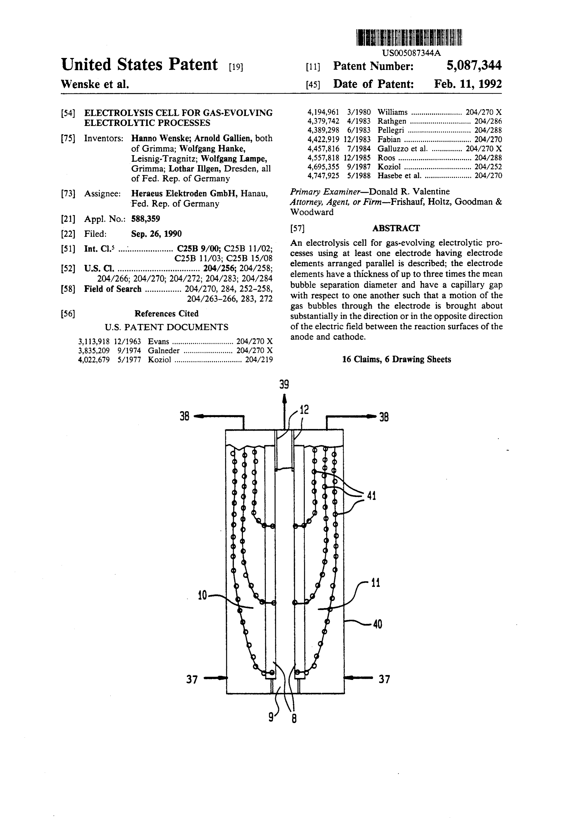
While the electrode element 1b shown in FIG. 10 has In FIG. 1, the basic structure of an electrolyte cell is horizontally extending, web-like profiled portions 23 on 65 shown. It has electrodes 8, which are formed of elec only one side, web-like profiled portions 24, 24' are trode elements according to the invention. To show the disposed on both sides on the electrode element 1c of gas bubble distribution more clearly, the course of the FIG. 11. The profiled portions 24 on one side, having gas bubbles is shown in simplified form in the form of
Page 12
bubble tracks 41, and the electrolysis cell has a rela construction surface area can be approximately 2. The tively large electrode spacing and wide degassing gas bubbles formed at the end faces and reactive faces 2 chambers 10, 11. One of the essential prerequisites for of the electrode elements 1, 1a, 1b, 1c, 1d, 28, 29, 30, 31 the function of the electrolysis cell according to the are located in the region of influence of the capillary invention is the electrodes 8 formed of the electrode 5 gap. Because of the gas bubble formation, a pressure elements according to the invention. buildup occurs in the reaction chamber 9; this is the The arrows in FIG. 1 indicate the following: the feed cause for the gas transport transverse to the electrode of electrolyte 37; gas removal 38; and mixed gas re plane. In FIG. 4, the path of a gas bubble 6 through the moval 39. capillary gap 4 between the electrode element 1 is The connections between the reaction chamber and 10 shown. To the same extent, the electrolyte is exchanged degassing chambers 10, 1 are at most the size of one between the degassing chamber 10, 11 and the reaction capillary gap; it is even better if these chambers are chamber 9. There are practically no gas bubbles that are completely sealed off from one another, thus preventing freely movable in the electrolyte of the reaction cham any electrolyte transport between the electrodes 8 and ber 9. They are moved along the electrode surface the cell housing 40 from causing flow-dictated disturb- 15 under the influence of the capillary effect, and are ances that might cause bubbles 6 to separate from the "sucked' into the capillary gap 4. This substantially electrode reaction face and enter the reaction chamber reduces the electrical resistance of the electrolyte. 9. It should also be pointed out that the width 5 of the A cell structure thus becomes available which hy electrode elements 1 can be adapted to requirements in draulically divides the electrolysis cell into a common 20 terms of the smallest possible ohmic voltage drop in the reaction chamber 9 and separate degassing chambers 10, electrode material. The same is true for the dimension 11. ing of the capillary gap 4, in order to achieve unim The purity of the gases generated depends defini peded hydraulic conditions in the reaction chamber of tively on the quality of the electrodes. The electrode the electrolysis cell.
spacing can also have an effect on the purity of the 25 We claim:
gases. To prevent coagulation of gas bubbles, a spacing 1. An electrolysis cell for gas-evolving electrolytic of at least three times the bubble separation diameter processes, in particular for water and chlor-alkali elec must exist between the electrodes 8. Coagulation of gas trolysis, using at least one electrode with electrode bubbles leads to the formation of mixed gas in the reac elements arranged parallel and forming the anode and tion chamber 9. 30 cathode,
Nevertheless, the aim should be to have the smallest characterized in that possible electrode spacing, because that lowers the the electrode elements (1, 1a, 1b, 1c, 1d, 15, 16, 28, 29, ohmic resistance. The electrolyte exchange between the 30, 31) have a thickness (3,33) of up to three times degassing chambers 10, 11 and the reaction chamber 9 is the means bubble separation diameter, and more intensive the smaller (narrower) the reaction 35 have a capillary gap (4) relative to one another such chamber 9 (or electrode spacing). that
Gas bubbles 6 that nevertheless separate from the the direction of motion of the gas bubbles through the electrode 8 and migrate into the reaction chamber 9 electrode (8) is substantially parallel to the direc cause the aforementioned insignificant formation of tion of an electrical field formed between the reac mixed gas. The bubbles cannot cause contamination of 40 tion faces of the anode and cathode, and wherein the pure gas, because they would coagulate with the the electrode elements (1, 1a, 1b, 1c, 1d, 15, 16, 28, bubbles formed there even before reaching the counter 29, 30, 31) comprise profiled portions (23, 24, 24", electrode. Their bubble diameter would then be too 25, 32) for defining the capillary gap (4). large for transport through a capillary gap 4 of the 2. The electrolysis cell of claim 1, electrode 8 or in the sealing region with respect to the 45 characterized in that housing wall. The separation of the pure gases in the the electrode elements (1, 1a, 1b, 1c, 1d, 15, 16, 28, 29, upper cell region is effected by means of one or more 30, 31) are blades, strips or foils bulkheads 12, which are submerged below the surface having a thickness (3, 33) of 450 micrometers at most. of the liquid. 3. The electrolysis cell of claim 2, Optimal functioning of the electrode 6 is achieved if 50 characterized in that its structure is finely arranged and uniform. Such prop the electrode elements (1, 1a, 1b, 1c, d, 15, 16, 28, 29, erties are best attained by tightly packed and uniformly 30, 31) are produced from a glass-metal foil strip. profiled electrode elements 1, 1a, 1b, 1c, 1d, 28, 29, 30, 4. The electrolysis cell of claim 1, 31. characterized in that
The electrolysis cell, equipped with an electrode 55 the width (5) of the electrode elements (1, 1a, 1b, 1c, made of electrode elements according to the invention, 1d, 15, 16, 28, 29, 30, 31) is at least ten times the functions as follows: width of the capillary cap (4). The large number of electrode elements 1, 1a, 1b, 1c, 5. The electrolysis cell of claim 4, 1d, 28, 29, 30, 31 of the electrode 8 (approximately 40 to characterized in that 50 electrode elements per centimeter) makes the elec- 60 the electrode elements (1, 1a, 1b, 1c, 1d, 15, 16, 28, 29, trode surface highly uniform. This means that the elec 30, 31) are produced from a glass-metal foil strip. tric field is made sufficiently uniform, as is the current 6. The electrolysis cell of claim 1, density load. Consequently, overloading and attendant characterized in that premature wear of the electrocatalytic coating are the electrode elements are a component of a planar avoided. Furthermore, this makes it possible to increase 65 structure folded on alternate sides, which have the surface area involved in the reaction to a value perforations (21) in the region of its folding edges larger than the structural surface area. Under favorable (20).
conditions, the ratio of active reaction surface area to 7. The electrolysis cell of claim 6,
Page 13
characterized in that elements (14), which have a net-like, honeycomb, the perforations (21) are uniformly distributed. O WOWe Structure.
8. The electrolysis cell of claim 6, 14. The electrolysis cell of claim 1, characterized in that characterized in that the electrode elements (1, 1a, 1b, c, 1d, 15, 16, 28, 29, 5 the electrode elements (1, 1a, 1b, 1c, 1d, 15, 16, 28, 29, 30, 31) are produced from a glass-metal foil strip. 30, 31) are produced from a glass-metal foil strip. 9. The electrolysis cell of claim 1, 15. An electrolysis cell, having characterized in that at least one electrode with electrode elements, ar the profiled portions (23, 24, 24", 25) are embossed ranged generally parallel to each other, serving as
anode and cathode, 10. The electrolysis cell of claim 1, for a gas-evolving electrolysis process in which a characterized in that the profiled portions (23, 24, 24', 32) have a web-like bubble of gas evolved, upon growing to a charac structure extending transversely to the electrode teristic means separation diameter, separates from plane. 15 its nucleus or initial formation point and moves by 11. The electrolysis cell of claim 1, adhesion along a surface of said at least one elec characterized in that trode, characterized in that the profiled portions (25) are embodied as knob-like the electrode elements (1, 1a, 1b, 1b, 1d, 15, 16, 28, 29,
12. The electrolysis cell of claim 1, 20 30, 31) have a thickness (3, 33) of up to three times characterized in that the electrode elements (1, 1a, 1b, said mean bubble separation diameter; 1c, 1d) laterally defining the electrode (8), and the have a capillary gap (4) relative to one another di lower closure of the electrode (8) toward the inner mensioned such that the direction of motion of the wall of the cell housing (40) is sealed off, except for gas bubbles through the electrode (8) is substan at most a gap corresponding to the capillary gap (4) 25 tially parallel to the direction of an electrical field between the electrode elements (1, 1a, 1b, 1c, d, formed between reaction faces of the anode and 15, 16, 28, 29, 30, 31), and the degassing chambers cathode; and (10, 11) are separated in a gas-tight manner in the the electrode elements (28, 29) are together wound in upper cell region, at least up to the surface of the a spiral configuration.
electrolyte, by a bulkhead (12, 13). 30 16. The electrolysis cell of claim 15, 13. The electrolysis cell of claim 12, characterized in that characterized in that the electrode elements (1, 1a, 1b, 1c, 1d, 15, 16, 28, 29, the spacing between the anode and cathode is defined 30, 31) are produced from a glass-metal foil strip. by one or more electrolyte-proof dielectric spacer c k
Provenance
- Collection
- Cited prior art
- Original PDF
- patentimages.storage.googleapis.com →
- Filed
- 1990-09-26
- Pages
- 13
- Method
- pdftotext (the PDF's own text layer) + pdftoppm 300dpi page scans
- Source
- Google Patents bibliographic record
- Granted
- 1992-02-11
- Inventors
- Hanno Wenske; Arnold Gallien; Wolfgang Hanke; Wolfgang Lampe; Lothar Illgen; Heraeus Elektroden GmbH
- Transcribed from
- patentimages.storage.googleapis.com →