patent · US5048501
Fuel economy system for internal combustion engines
17 September 1991
Page 1 — bibliographic record
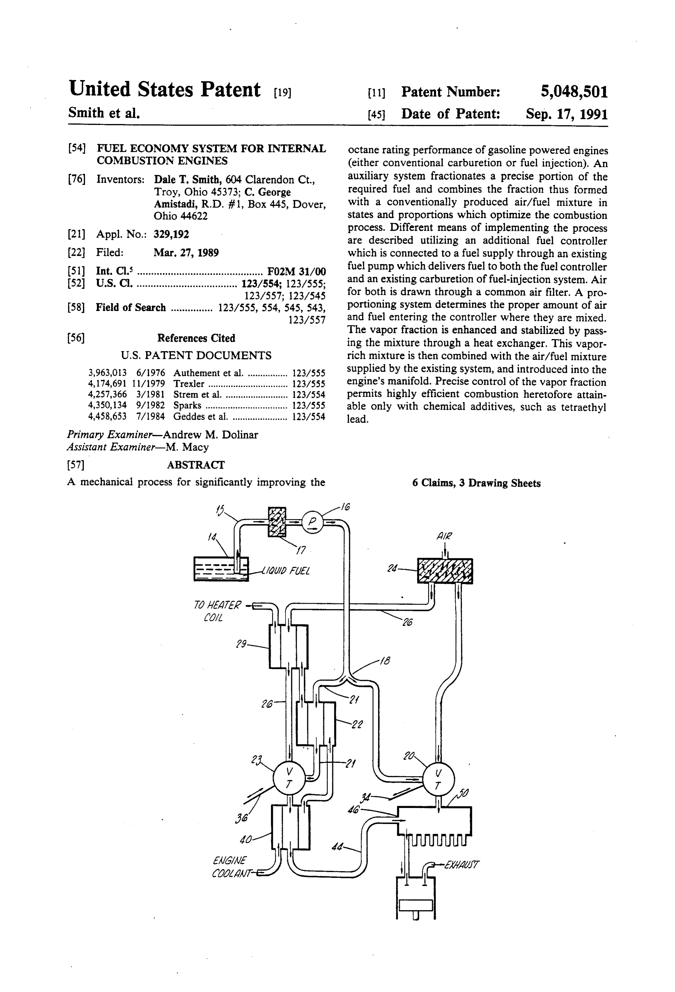
United States Patent (19) 11) Patent Number: 5,048,501 Smith et al. 45 Date of Patent: Sep. 17, 1991 54 FUEL ECONOMY SYSTEM FOR INTERNAL octane rating performance of gasoline powered engines COMBUSTON ENGINES (either conventional carburetion or fuel injection). An 76 Inventors: Dale T. Smith, 604 Clarendon Ct., auxiliary system fractionates a precise portion of the Troy, Ohio 45373; C. George required fuel and combines the fraction thus formed Amistadi, R.D. #1, Box 445, Dover, with a conventionally produced air/fuel mixture in Ohio 4.4622 states and proportions which optimize the combustion (21) Appl. No.: 329,192 process. Different means of implementing the process are described utilizing an additional fuel controller (22 Filed: Mar. 27, 1989 which is connected to a fuel supply through an existing (51) Int. Cl. ............................................. F02M 31/00 fuel pump which delivers fuel to both the fuel controller (52 U.S. Cl. .................................... 123/554; 123/555; and an existing carburetion of fuel-injection system. Air 123/557; 123/545 for both is drawn through a common air filter. A pro 58 Field of Search ............... 123/555, 554, 545, 543, portioning system determines the proper amount of air 123/557 and fuel entering the controller where they are mixed.
(56) References Cited The vapor fraction is enhanced and stabilized by pass ing the mixture through a heat exchanger. This vapor
3,963,013 6/1976 Authement et al. ................ 123/555 supplied by the existing system, and introduced into the 4, 174,691 1 1/1979 Trexler .................... ... 123/555 engine's manifold. Precise control of the vapor fraction 4,257,366 3/1981 Strem et al. ......... ... 123/554 permits highly efficient combustion heretofore attain 4,350,134 9/1982 Sparks ................................. 123/555 able only with chemical additives, such as tetraethyl 4,458,653 7/1984 Geddes et al. ...................... 123/554 lead.
Primary Examiner-Andrew M. Dolinar
Assistant Examiner-M. Macy
A mechanical process for significantly improving the 6 Claims, 3 Drawing Sheets
Page 2
Drawing sheet — no readable text.
Page 3
Drawing sheet — no readable text.
Page 4
Drawing sheet — no readable text.
Page 5
expectations in light of the fact that many inventions
FUEL ECONOMY SYSTEM FOR INTERNAL continue to be advanced.
COMBUSTON ENGINES
SUMMARY OF THE INVENTION
FIELD OF THE INVENTION This invention provides an auxiliary fuel/air system This invention relates to a combustion efficiency used in conjunction with conventional carbureted fuel process, and systems implementing it, which supply a /air mixtures for gasoline-powered internal combustion precise mixture of fuel and air in the vapor and aerosol engines that affords significantly higher fuel economies states to the combustion chambers of an internal com with substantial gains in performance. In testing the bustion engine. 10 system of invention, gas mileage has been improved by
BACKGROUND OF THE INVENTION as much as 100% in vehicles ranging from small autom biles, pick-up trucks to large recreational vehicles. Al
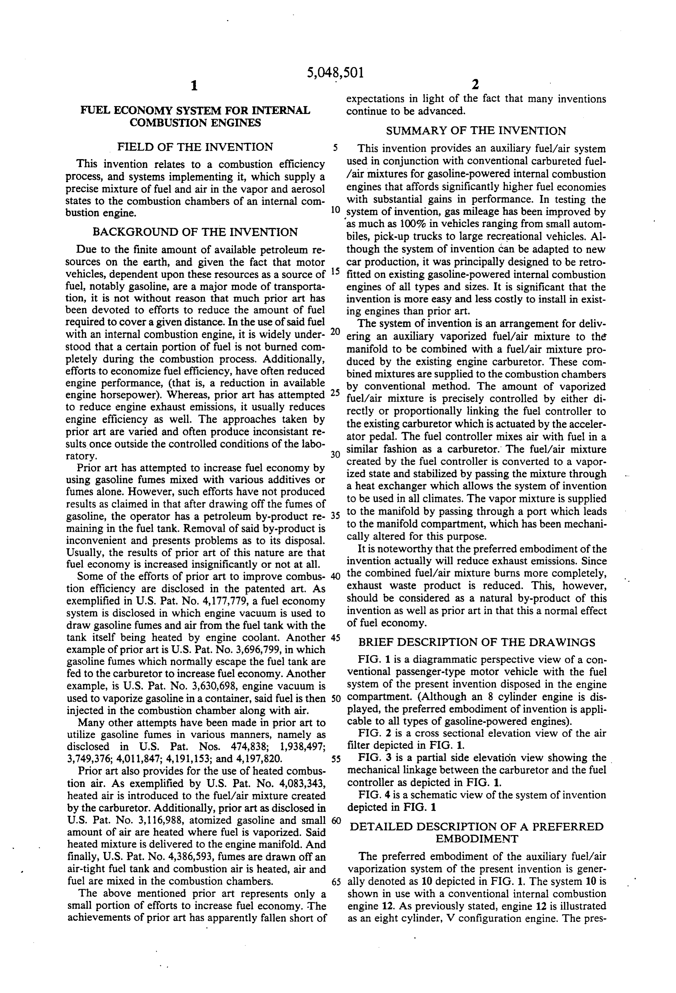
Due to the finite amount of available petroleum re though the system of invention can be adapted to new Sources on the earth, and given the fact that motor 15 car production, it was principally designed to be retro vehicles, dependent upon these resources as a source of fitted on existing gasoline-powered internal combustion fuel, notably gasoline, are a major mode of transporta engines of all types and sizes. It is significant that the tion, it is not without reason that much prior art has invention is more easy and less costly to install in exist been devoted to efforts to reduce the amount of fuel ing engines than prior art.
required to cover a given distance. In the use of said fuel 20 The system of invention is an arrangement for deliv with an internal combustion engine, it is widely under ering an auxiliary vaporized fuel/air mixture to the stood that a certain portion of fuel is not burned com manifold to be combined with a fuel/air mixture pro pletely during the combustion process. Additionally, duced by the existing engine carburetor. These com efforts to economize fuel efficiency, have often reduced bined mixtures are supplied to the combustion chambers engine performance, (that is, a reduction in available by conventional method. The amount of vaporized engine horsepower). Whereas, prior art has attempted 25 fuel/air mixture is precisely controlled by either di to reduce engine exhaust emissions, it usually reduces rectly or proportionally linking the fuel controller to engine efficiency as well. The approaches taken by the existing carburetor which is actuated by the acceler prior art are varied and often produce inconsistant re ator pedal. The fuel controller mixes air with fuel in a sults once outside the controlled conditions of the labo similar fashion as a carburetor. The fuel/air mixture ratory.
Prior art has attempted to increase fuel economy by created by the fuel controller is converted to a vapor using gasoline funes mixed with various additives or ized state and stabilized by passing the mixture through a heat exchanger which allows the system of invention fumes alone. However, such efforts have not produced to results as claimed in that after drawing off the fumes of to be the used in all climates. The vapor mixture is supplied manifold by passing through a port which leads gasoline, the operator has a petroleum by-product re 35 maining in the fuel tank. Removal of said by-product is to the manifold compartment, which has been mechani inconvenient and presents problems as to its disposal. cally altered for this purpose.
Usually, the results of prior art of this nature are that It is noteworthy that the preferred embodiment of the fuel economy is increased insignificantly or not at all. invention actually will reduce exhaust emissions. Since Some of the efforts of prior art to improve combus the combined fuel/air mixture burns more completely, tion efficiency are disclosed in the patented art. As exhaust waste product is reduced. This, however, exemplified in U.S. Pat. No. 4,177,779, a fuel economy should be considered as a natural by-product of this system is disclosed in which engine vacuum is used to invention as well as prior art in that this a normal effect draw gasoline fumes and air from the fuel tank with the of fuel economy.
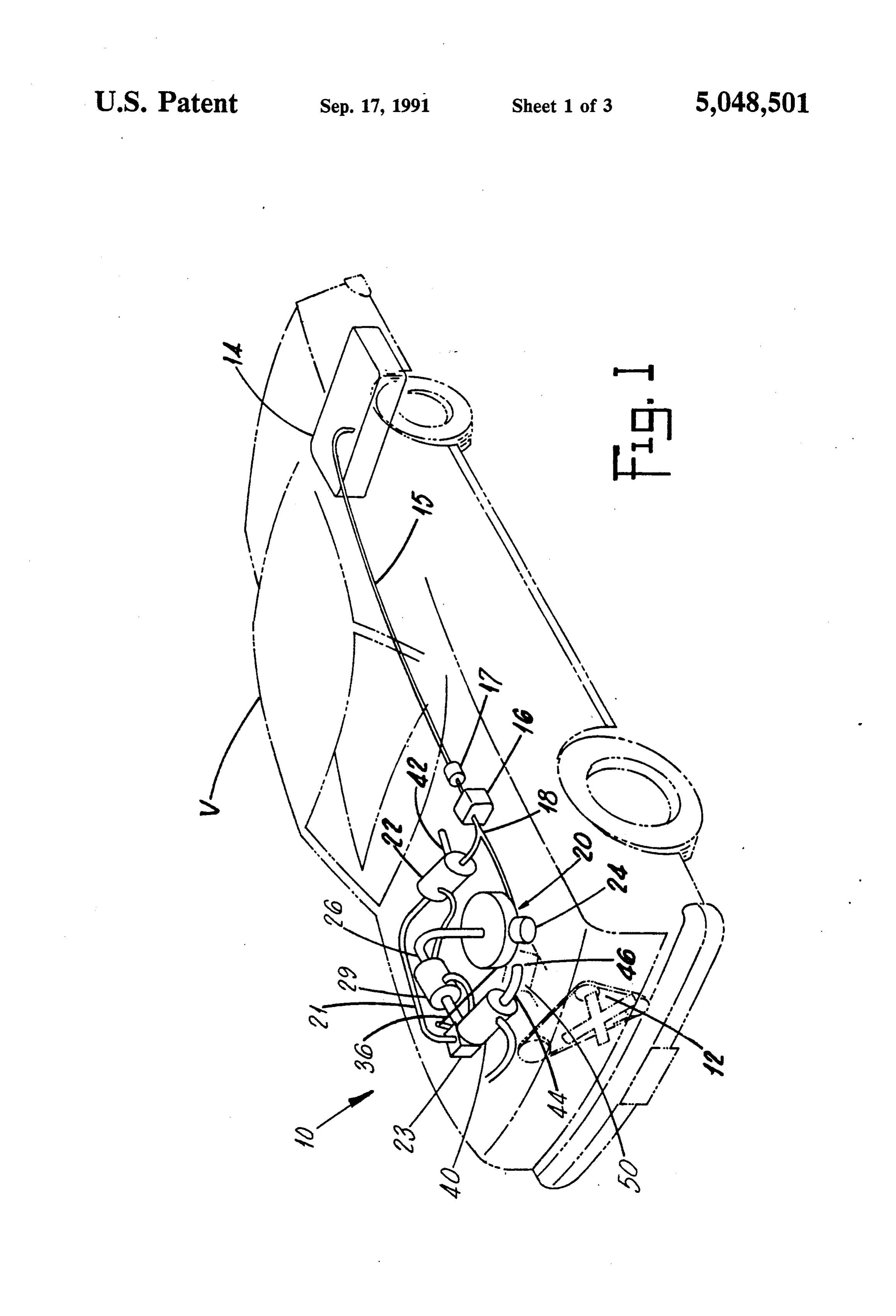
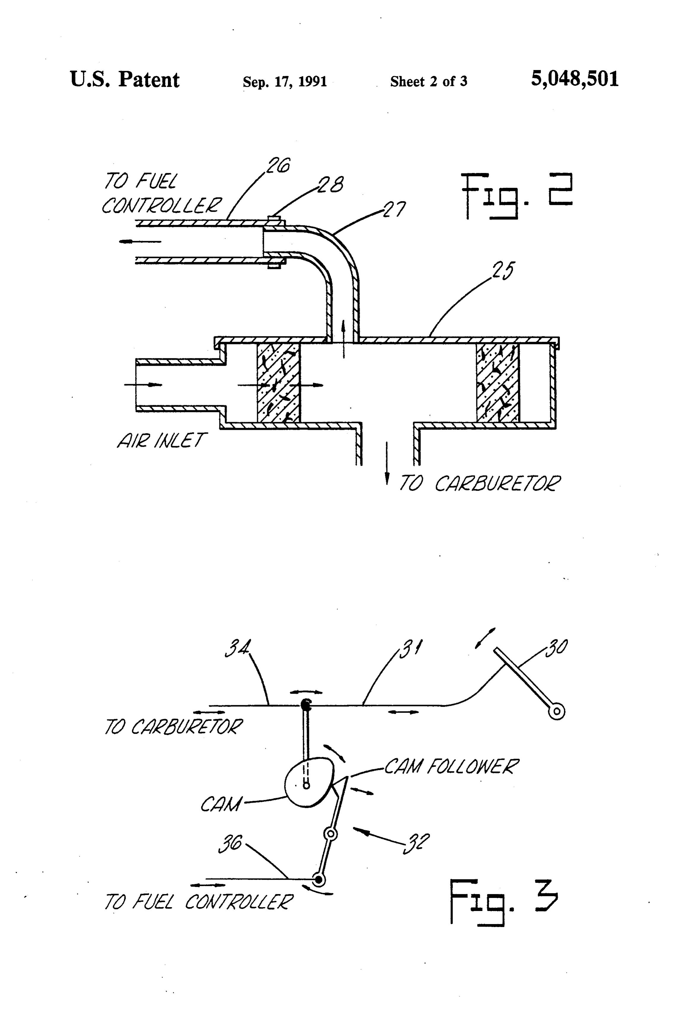
tank itself being heated by engine coolant. Another 45 BRIEF DESCRIPTION OF THE DRAWINGS example of prior art is U.S. Pat. No. 3,696,799, in which gasoline fumes which normally escape the fuel tank are FIG. 1 is a diagrammatic perspective view of a con fed to the carburetor to increase fuel economy. Another ventional passenger-type motor vehicle with the fuel example, is U.S. Pat. No. 3,630,698, engine vacuum is system of the present invention disposed in the engine used to vaporize gasoline in a container, said fuel is then 50 compartment. (Although an 8 cylinder engine is dis injected in the combustion chamber along with air. played, the preferred embodiment of invention is appli Many other attempts have been made in prior art to cable to all types of gasoline-powered engines). utilize gasoline fumes in various manners, namely as FIG. 2 is a cross sectional elevation view of the air disclosed in U.S. Pat. Nos. 474,838; 1,938,497; filter depicted in FIG. 1.
3,749,376; 4,011,847; 4,191,153; and 4,197,820. 55 FIG. 3 is a partial side elevation view showing the Prior art also provides for the use of heated combus mechanical linkage between the carburetor and the fuel tion air. As exemplified by U.S. Pat. No. 4,083,343, controller as depicted in FIG. 1.
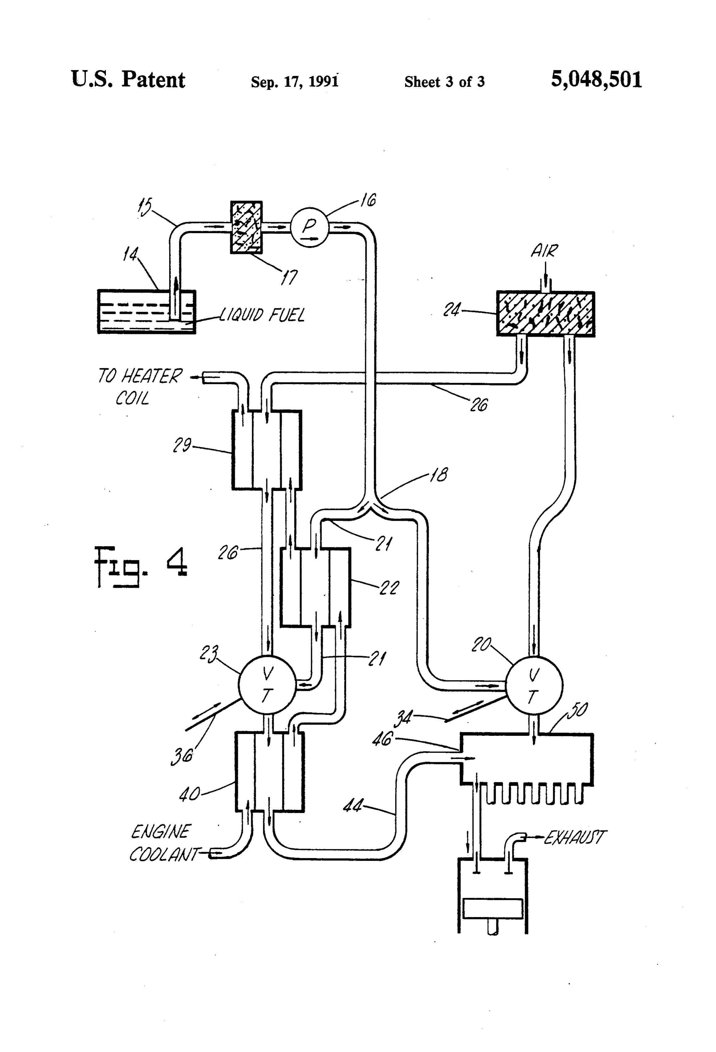
heated air is introduced to the fuel/air mixture created FIG. 4 is a schematic view of the system of invention by the carburetor. Additionally, prior art as disclosed in depicted in FIG. 1
U.S. Pat. No. 3,116,988, atomized gasoline and small DETAILED DESCRIPTION OF A PREFERRED amount of air are heated where fuel is vaporized. Said EMBOOIMENT heated mixture is delivered to the engine manifold. And finally, U.S. Pat. No. 4,386,593, fumes are drawn off an The preferred embodiment of the auxiliary fuel/air air-tight fuel tank and combustion air is heated, air and vaporization system of the present invention is gener fuel are mixed in the combustion chambers. 65 ally denoted as 10 depicted in FIG. 1. The system 10 is The above mentioned prior art represents only a shown in use with a conventional internal combustion small portion of efforts to increase fuel economy. The engine 12. As previously stated, engine 12 is illustrated achievements of prior art has apparently fallen short of as an eight cylinder, V configuration engine. The pres
Page 6
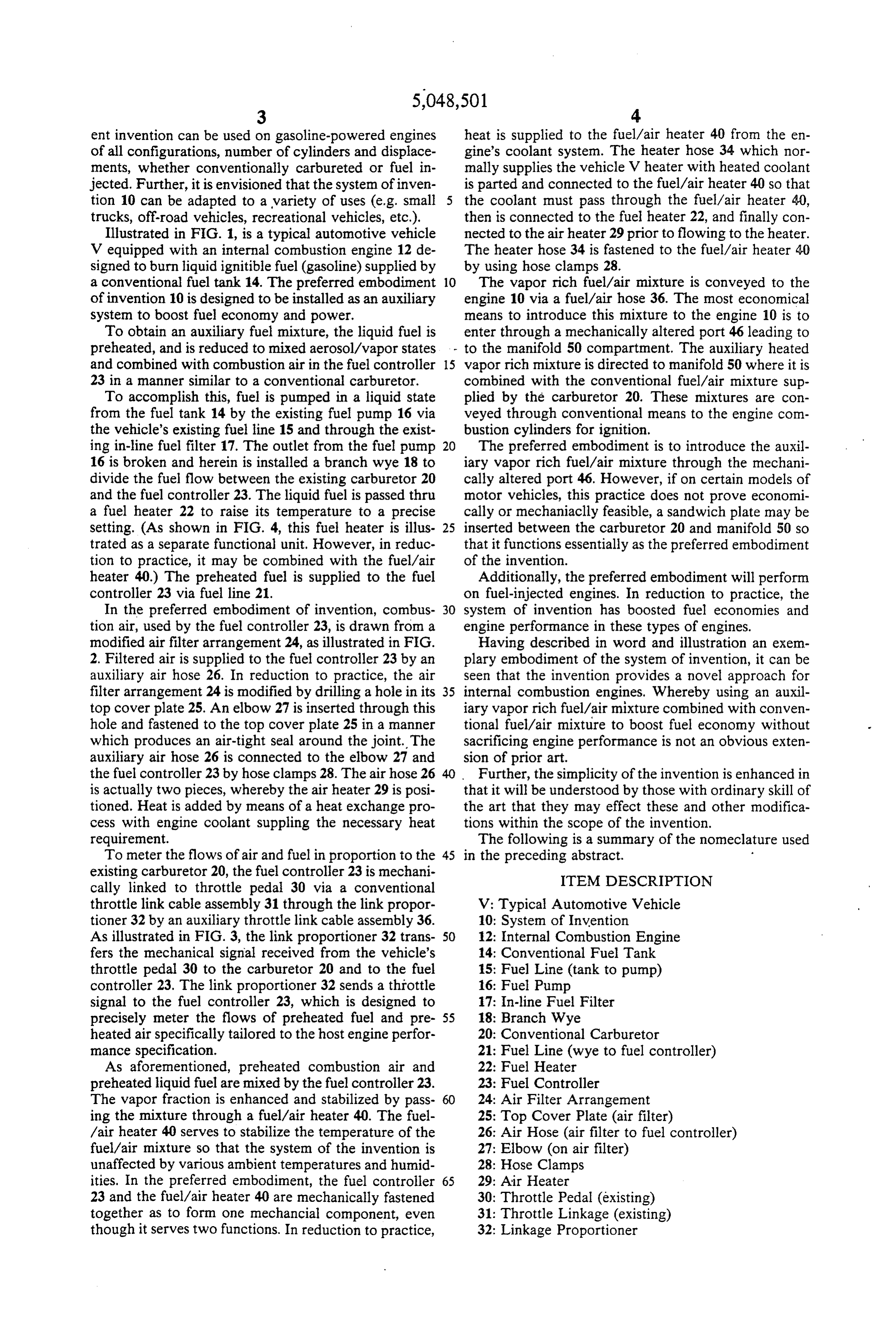
ent invention can be used on gasoline-powered engines heat is supplied to the fuel/air heater 40 from the en of all configurations, number of cylinders and displace gine's coolant system. The heater hose 34 which nor ments, whether conventionally carbureted or fuel in mally supplies the vehicle V heater with heated coolant jected. Further, it is envisioned that the system of inven is parted and connected to the fuel/air heater 40 so that tion 10 can be adapted to a variety of uses (e.g. small the coolant must pass through the fuel/air heater 40, trucks, off-road vehicles, recreational vehicles, etc.). then is connected to the fuel heater 22, and finally con Illustrated in FIG. 1, is a typical automotive vehicle nected to the air heater 29 prior to flowing to the heater. V equipped with an internal combustion engine 12 de The heater hose 34 is fastened to the fuel/air heater 40 signed to burn liquid ignitible fuel (gasoline) supplied by by using hose clamps 28.
a conventional fuel tank 14. The preferred embodiment 10 The vapor rich fuel/air mixture is conveyed to the of invention 10 is designed to be installed as an auxiliary engine 10 via a fuel/air hose 36. The most economical system to boost fuel economy and power. means to introduce this mixture to the engine 10 is to To obtain an auxiliary fuel mixture, the liquid fuel is enter through a mechanically altered port 46 leading to preheated, and is reduced to mixed aerosol/vapor states to the manifold 50 compartment. The auxiliary heated and combined with combustion air in the fuel controller 15 vapor rich mixture is directed to manifold 50 where it is 23 in a manner similar to a conventional carburetor. combined with the conventional fuel/air mixture sup To accomplish this, fuel is pumped in a liquid state plied by the carburetor 20. These mixtures are con from the fuel tank 14 by the existing fuel pump 16 via veyed through conventional means to the engine com the vehicle's existing fuel line 15 and through the exist bustion cylinders for ignition.
ing in-line fuel filter 17. The outlet from the fuel pump 20 The preferred embodiment is to introduce the auxil 16 is broken and herein is installed a branch wye 18 to iary vapor rich fuel/air mixture through the mechani divide the fuel flow between the existing carburetor 20 cally altered port 46. However, if on certain models of and the fuel controller 23. The liquid fuel is passed thru motor vehicles, this practice does not prove economi a fuel heater 22 to raise its temperature to a precise cally or mechaniaclly feasible, a sandwich plate may be setting. (As shown in FIG. 4, this fuel heater is illus 25 inserted between the carburetor 20 and manifold 50 so trated as a separate functional unit. However, in reduc that it functions essentially as the preferred embodiment tion to practice, it may be combined with the fuel/air of the invention.
heater 40.) The preheated fuel is supplied to the fuel Additionally, the preferred embodiment will perform controller 23 via fuel line 21. on fuel-injected engines. In reduction to practice, the In the preferred embodiment of invention, combus 30 system of invention has boosted fuel economies and tion air, used by the fuel controller 23, is drawn from a engine performance in these types of engines. modified air filter arrangement 24, as illustrated in FIG. Having described in word and illustration an exem 2. Filtered air is supplied to the fuel controller 23 by an plary embodiment of the system of invention, it can be auxiliary air hose 26. In reduction to practice, the air seen that the invention provides a novel approach for filter arrangement 24 is modified by drilling a hole in its 35 internal combustion engines. Whereby using an auxil top cover plate 25. An elbow 27 is inserted through this iary vapor rich fuel/air mixture combined with conven hole and fastened to the top cover plate 25 in a manner tional fuel/air mixture to boost fuel economy without which produces an air-tight seal around the joint. The sacrificing engine performance is not an obvious exten auxiliary air hose 26 is connected to the elbow 27 and sion of prior art.
the fuel controller 23 by hose clamps 28. The air hose 26 Further, the simplicity of the invention is enhanced in is actually two pieces, whereby the air heater 29 is posi that it will be understood by those with ordinary skill of tioned. Heat is added by means of a heat exchange pro the art that they may effect these and other modifica cess with engine coolant suppling the necessary heat tions within the scope of the invention. requirement. The following is a summary of the nomeclature used To meter the flows of air and fuel in proportion to the 45 in the preceding abstract. d existing carburetor 20, the fuel controller 23 is mechani ITEM DESCRIPTION cally linked to throttle pedal 30 via a conventional throttle link cable assembly 31 through the link propor V: Typical Automotive Vehicle tioner 32 by an auxiliary throttle link cable assembly 36. 10: System of Invention
As illustrated in FIG. 3, the link proportioner 32 trans SO 12: Internal Combustion Engine fers the mechanical signal received from the vehicle's 14: Conventional Fuel Tank throttle pedal 30 to the carburetor 20 and to the fuel 15: Fuel Line (tank to pump) controller 23. The link proportioner 32 sends a throttle 16: Fuel Pump signal to the fuel controller 23, which is designed to 17: In-line Fuel Filter precisely meter the flows of preheated fuel and pre 55 18: Branch Wye heated air specifically tailored to the host engine perfor 20: Conventional Carburetor mance specification. 21: Fuel Line (wye to fuel controller) As aforementioned, preheated combustion air and 22: Fuel Heater preheated liquid fuel are mixed by the fuel controller 23. 23: Fuel Controller
The vapor fraction is enhanced and stabilized by pass 24: Air Filter Arrangement ing the mixture through a fuel/air heater 40. The fuel 25: Top Cover Plate (air filter) /air heater 40 serves to stabilize the temperature of the 26: Air Hose (air filter to fuel controller) fuel/air mixture so that the system of the invention is 27: Elbow (on air filter) unaffected by various ambient temperatures and humid 28: Hose Clamps ities. In the preferred embodiment, the fuel controller 65 29: Air Heater 23 and the fuel/air heater 40 are mechanically fastened 30: Throttle Pedal (existing) together as to form one mechancial component, even 31: Throttle Linkage (existing) though it serves two functions. In reduction to practice, 32: Linkage Proportioner
Page 7
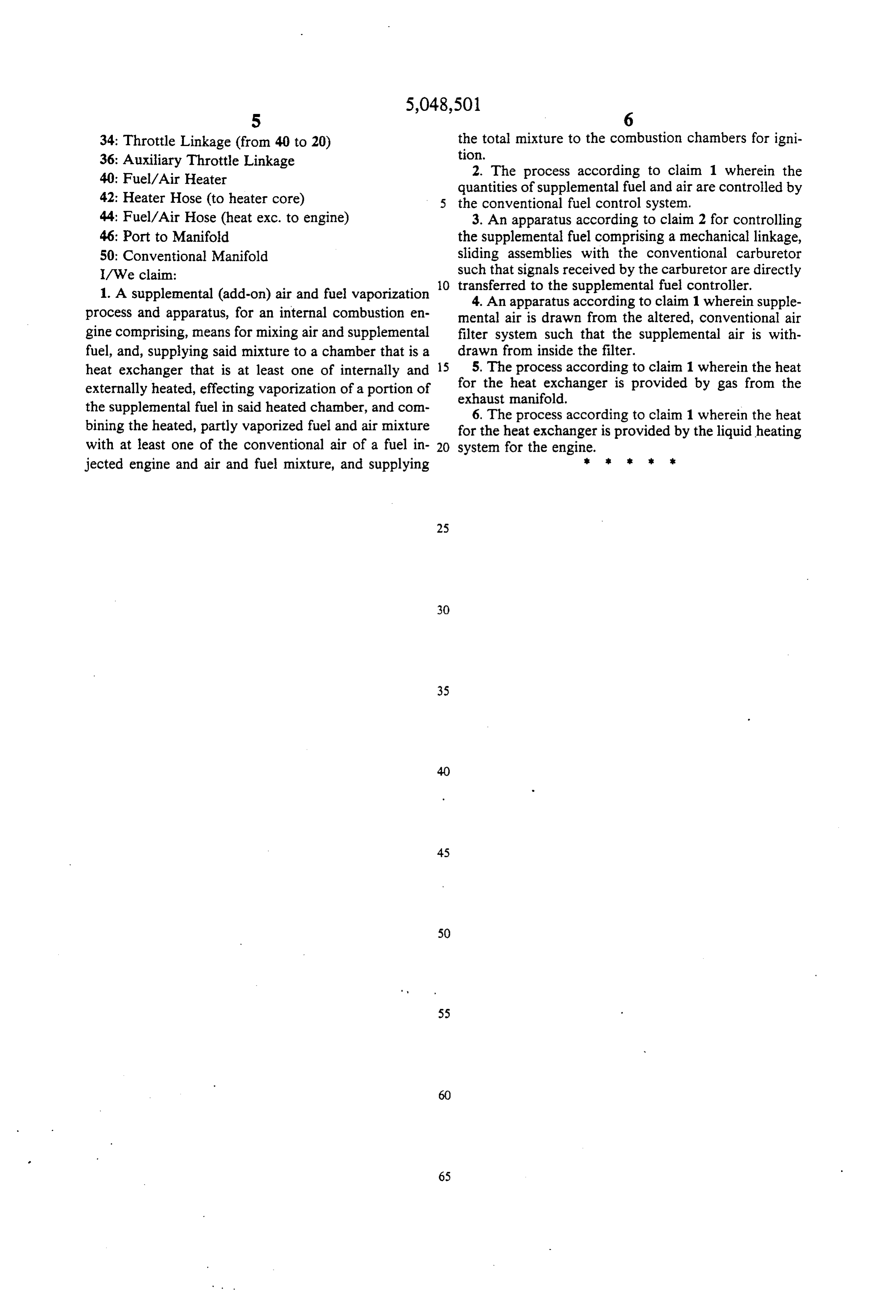
34: Throttle Linkage (from 40 to 20) the total mixture to the combustion chambers for igni 36: Auxiliary Throttle Linkage tion.
40: Fuel/Air Heater 2. The process according to claim 1 wherein the quantities of supplemental fuel and air are controlled by 42: Heater Hose (to heater core) the conventional fuel control System. 44: Fuel/Air Hose (heat exc. to engine) 3. An apparatus according to claim 2 for controlling 46: Port to Manifold the supplemental fuel comprising a mechanical linkage, 50: Conventional Manifold sliding assemblies with the conventional carburetor I/We claim: such that signals received by the carburetor are directly O transferred to the supplemental fuel controller.
1. A supplemental (add-on) air and fuel vaporization 4. An apparatus according to claim 1 wherein supple process and apparatus, for an internal combustion en mental air is drawn from the altered, conventional air gine comprising, means for mixing air and supplemental filter system such that the supplemental air is with fuel, and, supplying said mixture to a chamber that is a drawn from inside the filter. heat exchanger that is at least one of internally and 15 5. The process according to claim 1 wherein the heat externally heated, effecting vaporization of a portion of for the heat exchanger is provided by gas from the exhaust manifold.
the supplemental fuel in said heated chamber, and con 6. The process according to claim 1 wherein the heat bining the heated, partly vaporized fuel and air mixture for the heat exchanger is provided by the liquid heating with at least one of the conventional air of a fuel in 20 system for the engine.
jected engine and air and fuel mixture, and supplying
Provenance
- Collection
- Cited prior art
- Original PDF
- patentimages.storage.googleapis.com →
- Filed
- 1989-03-27
- Pages
- 7
- Method
- pdftotext (the PDF's own text layer) + pdftoppm 300dpi page scans
- Source
- Google Patents bibliographic record
- Granted
- 1991-09-17
- Inventors
- Dale T. Smith; C. George Amistadi
- Transcribed from
- patentimages.storage.googleapis.com →