patent · US4257366
Fuel feed system and method for gasoline burning internal combustion engine
24 March 1981
Page 1 — bibliographic record
United States Patent (19) 11) 4,257,366 Strem et al. 45 Mar. 24, 1981 54 FUE, FEED SYSTEMAND METHOD FOR 4,106,453 8/1978 Burley .......................... 123/122 B X GASOL NE BURNING INTERNAL 4,167,165 9/1979 Finlay et al. ................. 123/122 AA COMBUSTION ENGINE Primary Examiner-Harry N. Haroian (75) Inventors: Robert C. Strem; Richie C. Strem, Attorney, Agent, or Firm-Flehr, Hohbach, Test, both of Newcastle; John H. Eberle, Albritton & Herbert
Colfax, all of Calif. 57 ABSTRACT (73) Assignee: Omnewtronics, Inc., Carson City, A system for feeding gasoline fuel into a gasoline burn Nev.
ing internal combustion engine is disclosed herein along (21) Appl. No.: 6,355 with its method of operation. In accordance with this 22 Filed: Jan. 25, 1979 system and method, gasoline fuel in a liquid state is supplied to a vaporization chamber where it is vapor (51) Int. Cl.............................................. F02M 31/00 ized and thereafter directed to the engine for combus 52 U.S. C. .................................................... 123/554 tion therein. In order to prevent this vaporized fuel (58) Field of Search ........ 123/122 R, 122 AC, 122 B, from condensing back to a liquid, a supply of air is 123/122 C, 122 D, 122 E, 122 F, 133, 34 R, 34 preheated to a controlled predetermined temperature A and directed into the vaporization chamber where it (56) References Cited combines with the vaporized fuel and is passed with the
3,667,436 6/1972 Reichelm ..................... 123/122 RX 9 Claims, 7 Drawing Figures
Page 2
Drawing sheet — no readable text.
Page 3
Drawing sheet — no readable text.
Page 4
Drawing sheet — no readable text.
Page 5
scribed in the co-pending applications will also become
FUEL FEED SYSTEM AND METHOD FOR apparent hereinafter.
GASOLINE BURNING INTERNAL COMBUSTION In view of the foregoing, one object of the present ENGINE invention is to provide an efficient and yet uncompli cated and economical system for feeding gasoline fuel
The present invention relates generally to gasoline into a gasoline burning internal combustion engine. burning internal combustion engines and more particu Another object of the present invention is to provide larly a system for and method of feeding gasoline fuel a system which improves upon gasoline usage in a gaso into an engine of this type. This system is an improve line burning internal combustion engine, ment over applicant's co-pending applications Ser. No. 10 Still another object of the present invention is to 862,947 filed Dec. 21, 1977 and entitled ASSEMBLY provide a system for feeding gasoline fuel into a gaso AND METHOD OF VAPORIZING LIQUID GAS line burning internal combustion engine, which system
OLINE FUEL AND SYSTEM, Ser. No. 856,494 filed does not require a carburetor but rather feeds directly Dec. 1, 1977, entitled ASSEMBLY AND METHOD into the intake manifold of the engine, thereby eliminat OF VAPORIZING LIQUID GASOLINE FUEL 15 tion ing the various disadvantages resulting from the utiliza AND SYSTEM, and Ser. No. 843,799 filed Oct. 20, of a carburetor.
1977, now U.S. Pat. No. 4,178,897 entitled SYSTEM Yet another object of the present invention is to pro AND METHOD OF FEEDING GASOLINE FUEL vide a fuel feed system which carries out the previous INTO AN INTERNAL COMBUSTION ENGINE. objects by first vaporizing liquid gasoline fuel before the The co-pending applications just recited provided a 20 fuel is introduced into the engine.
discussion of the drawbacks in conventional fuel feed Still another object of the present invention is to techniques in internal combustion engines and reference liquid fuela system provide
of the last-mentioned type wherein the vaporized without the direct application of is made thereto. These applications also discussed vari ous systems and methods for improving the way in 25 heat. Yet another object of the present invention is to mini which fuel is fed to such an engine. Broadly, these co mize and preferably eliminate the possibility that the pending applications disclose a fuel feed technique vaporized fuel in the last-mentioned system condenses whereby gasoline fuel in its liquid state is supplied to a back to a liquid state before reaching the engine. chamber where it is vaporized and thereafter directed Still another object of the present invention is to to the engine. Specific ways in which this is accom 30 provide a fuel feed system of the last-mentioned type plished are also disclosed. In a preferred embodiment, having an improved vaporization assembly. as disclosed in the most recently filed co-pending appli A further object of the present invention is to provide cation, Ser. No. 862,947, the system does not rely on a method offeeding fuel into a gasoline burning internal heat to vaporize the fuel but rather a specific assembly combustion engine, which method includes the various of vaporization plates and a stream of air. 35 objectives set forth above.
While the vaporization assembly justmentioned func These objects, as well as other objects and features, tions in a satisfactory manner for its intended purpose, are achieved by the particular system and method of the that is, to vaporize liquid gasoline, and while the com present invention as will become apparent hereinafter. bustion of this vaporized gasoline in the engine rather In this regard, for purposes of description, both the than liquid gasoline is highly desirable, there is never 40 present system and method will be described in relation theless room for improvement in the various ap to an internal combustion engine used for powering a proaches described in the co-pending applications. For vehicle, for example an automobile. However, it is to be example, in the approach taken in application Ser. No. understood that the present invention is equally applica 862,947, liquid fuel is vaporized on appropriate plates ble where the engine is provided for powering or driv within a vaporization chamber. A stream of air from the 45 ing other apparatus. Moreover, fuels other than gasoline ambient surroundings and ambient temperature is di may be utilized by the present invention and for pur rected through the vaporization chamber where it is poses of the present invention would be equivalent so saturated with the vaporized fumes and thereafter di long as they function in an internal combustion engine rected to the engine, specifically to its intake manifold. in the same manner as gaoline and, of course, so long as A specific drawback in this approach resides in the 50 they can be reduced to a vapor state from a liquid state possibility that some of the saturated fumes (vaporized in the manner to be described hereinafter. Regarding fuel) may condense back to liquid fuel between the time this latter point, it should be clear that diesel fuel, for it leaves the vaporization chamber and the time it enters example, would not be such a fuel. the intake manifold of the engine for combustion In accordance with the present invention, gasoline therein. This in turn reduces the overall efficiency of 55 fuel is supplied in a liquid statefrom a supply tank to a the engine. vaporization chamber where it is vaporized and thereaf As will be seen hereinafter, the approach taken in ter into the engine in its vaporized state for combustion accordance with the present invention at least reduces therein, as generally described in the previous cited and preferably eliminates the drawback just described co-pending applications. However, in the technique by preheating the carrier air before the latter enters the disclosed herein, a supply of air preheated to a con vaporization chamber and is saturated by the vaporized trolled predetermined temperature is also provided and fuel. As will also be seen, the overall vaporization as directed into the vaporization chamber wherein it is sembly designed in accordance with the present inven saturated with the vaporized fuel (fumes). This combi tion is significantly different than the assembly de nation of vaporized fuel and preheated air is thereafter scribed in the last mentioned co-pending application but 65 directed to the engine and, in this regard, the primary if nevertheless utilizes vaporization plates rather than heat not sole purpose for heating the carrier air is to prevent to vaporize the liquid fuel. Other differences between the vaporized gasoline carried thereby from condensing the approach taken herein and those approaches de to a liquid state before reaching the engine.
Page 6
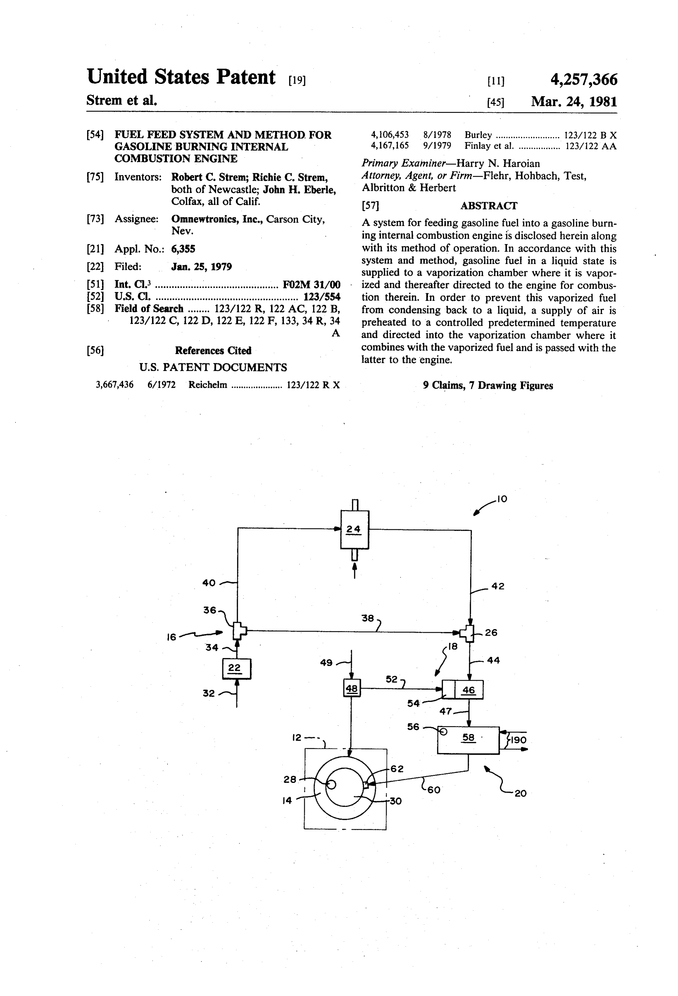
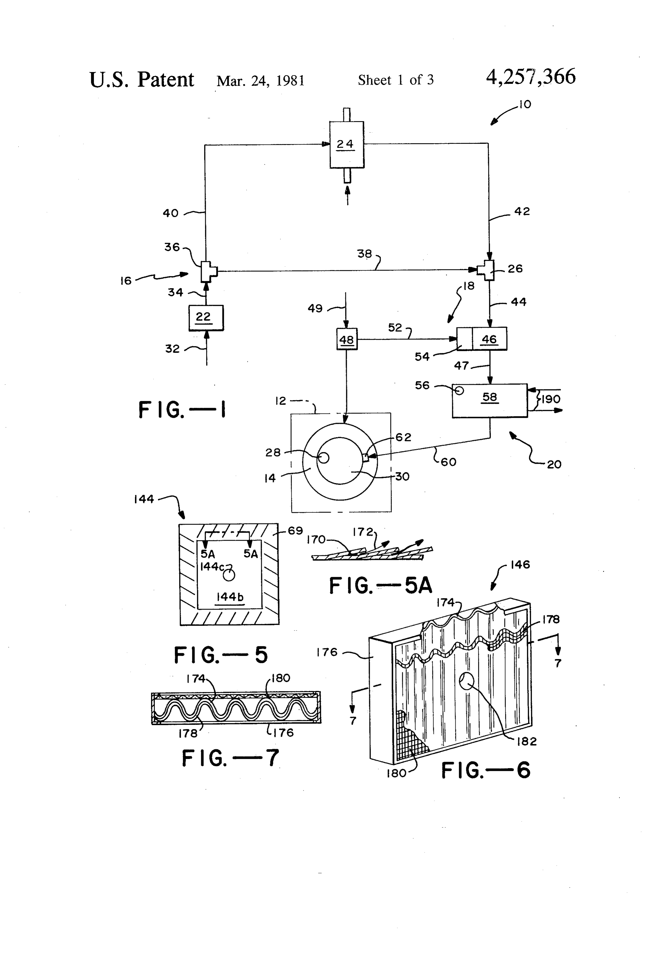
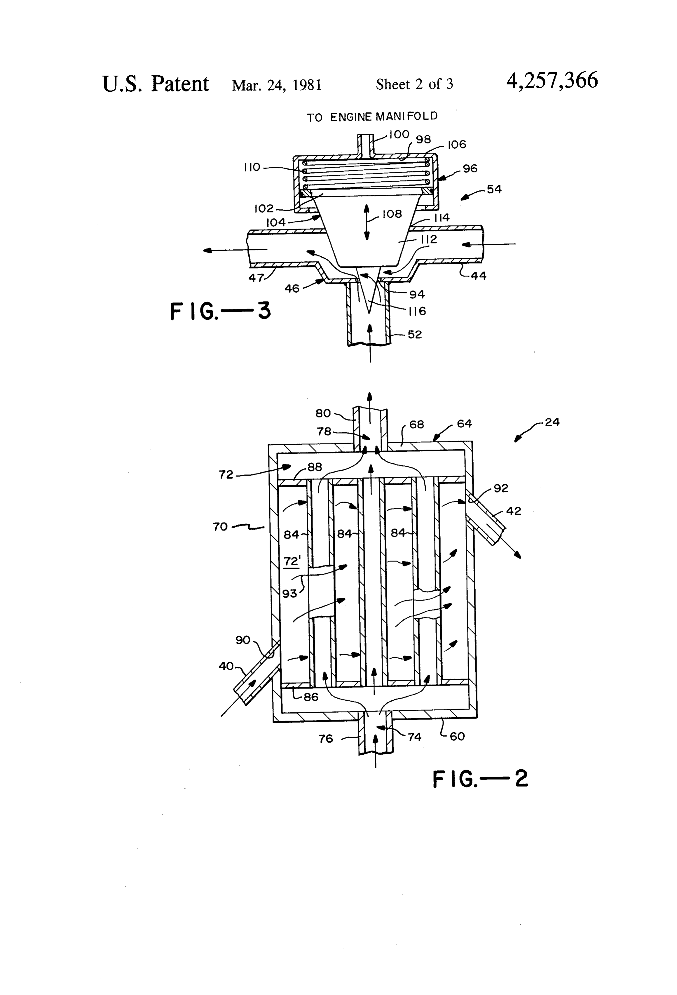
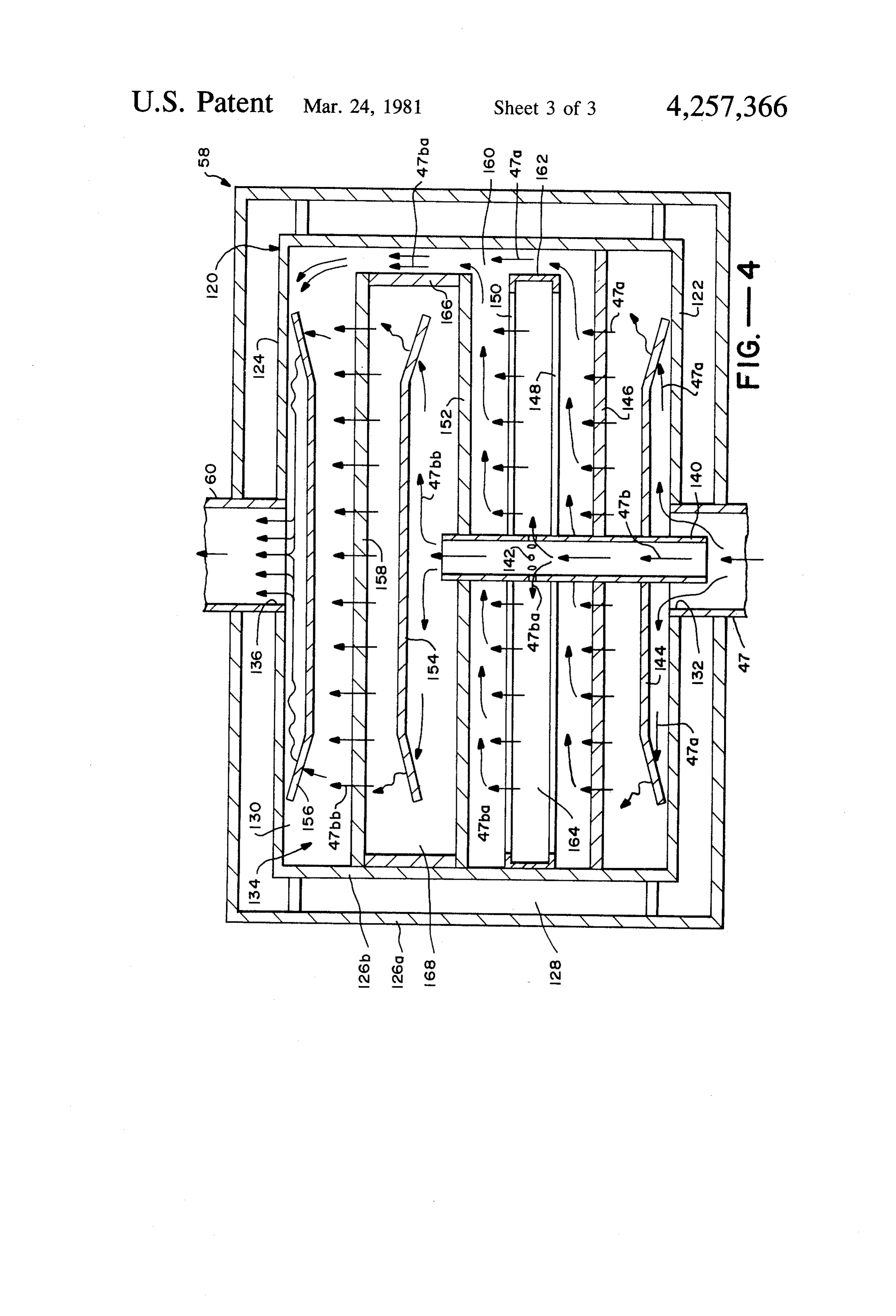
FIG, 1 is a block diagram of a system designed in latter section combines the liquid fuel and preheated air accordance with the present invention and provided for and causes the fuel to vaporize and saturate the air for feeding gasoline fuel into a gasoline burning internal combustion in engine 12.
combustion engine. Referring specifically to section 16 of system 10 as FIG. 2 is a diagrammatic illustration, in cross-section, shown in FIG. 1, this section includes an air filter 22, a of an assembly which comprises part of the system heat exchanger assembly 24 and an electrically actuated illustrated in FIG. 1 and which is provided for preheat solenoid valve 26. It also includes a temperature sensor ing a supply of ambient air. 28 and associated circuitry for controlling valve 26 in a FIG. 3 is a diagrammatic illustration, in vertical sec manner and for reasons to be described hereinafter. For tion, of an assembly which comprises part of the system 10 the moment, it should suffice to say that the tempera illustrated in FIG. 1 and which is provided for metering ture sensor 28 is located on top of a stainless steel cover liquid gasoline into a stream of temperature controlled 30 which is provided over carburetor 14, replacing its
conventional air filter. All of the components making
FIG, 4 is a diagrammatic illustration, in cross-section, of an assembly which comprises part of the system 15 up section 16 of system 10 thus far described, with the exception of heat exchanger assembly 24, are conven illustrated in FIG. 1 and which is provided for vaporiz tional and will not be further described from a struc ing liquid fuel in the stream illustrated in FIG. 3. tural standpoint. The structural details of assembly 24. FIG. 5 is plan view of a circulation fin comprising will however be described hereinafter with respect to part of the assembly illustrated in FIG. 4. FIG. 2.
FIG. 6 is a perspective view of a vaporization plate 20 As stated above, section 16 of system 10 provides a comprising part of the assembly illustrated in FIG. 4. supply of air which is preheated to a controlled prede FIG. 7 is a sectional view of the vaporization plate termined temperature. This is carried out by first draw illustrated in FIG. 6, taken generally along line 7-7 in ing in a stream of ambient air at ambient temperature F.G. 6. (for example 70 F) into and through air cleaner 22, as Turning now to the drawings, wherein like compo 25 indicated by arrow 32 which actually represents a suit ments are designated by like reference numerals able conduit or air hose. As indicated by arrow 34 (actu throughout the various figures, attention is first directed ally another suitable air hose), the filtered air stream is to FIG. 1. This figure illustrates an overall system 10 directed into a suitable tee connection 36 for dividing which is designed in accordance with the present inven the filtered stream between two paths as indicated by tion and which is provided for feeding gasoline fuel into 30 the arrows or air hoses 38 and 40. The stream 38 is a gasoline burning internal combustion engine, gener applied directly to one input of valve 26 which may or ally indicated by dotted lines at 12. The engine itself may not be opened to stream 38 as will be discussed may be of any conventional type which burns gasoline below. The other stream 40 passes into heat exchanger fuel and which would include all of the required com assembly 24 and thereafter out of the assembly as indi ponents to make it function properly including internal 35 cated by arrow (hose) 42. As the stream of air passes components, for example an intake manifold (not specif through assembly 24 it is heated, preferably utilizing the ically shown), and external but cooperating components heat from the exhaust fumes generated during the oper such as a carburetor 14, a fuel pump and cooperating ation of engine 12, as will be discussed hereinafter. In throttle (not shown) and the like. All of these compo any event, this preheated stream of air, now indicated at nents are conventional and, hence, are either not shown herein at all or only generally. In this regard, for reasons 42 (another hose) is directed to an alternate inlet of valve 26 which also may or may not be opened.
to be discussed hereinafter, it is important to note that A stream of air indicated by arrow (hose) 44 passes engine 12 is of the type which draws a vacuum through from the outlet of valve 26 and is preheated to a con its manifold when in operation. The level of this vac trolled temperature. More specifically, valve 26 oper uum depends upon the power developed by the engine, 45 ates rapidly between a deenergized state for passing hot that is, it is inversely proportional to power developed air stream 42 and an energized state for passing cold air by the engine. Therefore, during an idle condition (low stream 38, depending upon the temperature of the va power), the level of vacuum is high, for example 21 porized fuel carrier air stream entering the engine inches of mercury. At half power, the vacuum is at a which stream will be discussed hereinafter. For the low level, for example 7 inches of mercury, and at full 50 moment, it should suffice to say that the temperature of power the vacuum is at a minimum level, for example this latter stream is monitored by previously recited no vacuum at all. temperature sensor 28 located on the previously de Having described or mentioned the conventional scribed cover 30. More specifically, the valve, in re features of engine 12 which are necessary to a full un sponse to conventional control circuitry including sen derstanding of the present invention, attention is now 55 sor 28, is rapidly energized and de-energized to main directed to the various components making up system tain the stream at a predetermined temperature, specifi 10 which, as stated, is designed in accordance with the cally between about 140°, 180° F. in a preferred embodi present invention. In this regard, some of these compo ment and most preferably about 150 F. Obviously, nents are themselves conventional and therefore will should the stream fall below the predetermined temper not be described in detail while others are not conven 60 ature, a greater proportion of the heated stream will be tional and will be shown in more detail in later figures. passed by valve 26 as compared to the ambient stream. For purposes of description, system 10 is divided into On the other hand, should the combination stream ex three sections 16, 18 and 20. As will be seen hereinafter, ceed the predetermined temperature, a greater propor section 16 provides a supply of air which is preheated to tion of ambient air will be passed through the valve. a controlled predetermined temperature and section 18 65 While it is necessary to the present invention to provide provides a metered supply of gasoline fuel in liquid state a preheated stream of air for carrying the vaporized from a supply tank either directly to engine 12 for con fuel, as stated previously, it is also important not to ventional combustion therein or to section 20. This overheat this air. If air with vapor is overheated the
Page 7
combustibility of the mixture does not burn in the cylin this is desired or for utilizing section 20 even though the der evenly causing loss of power. engine may be cold.
From the foregoing description of section 16, it As will be seen hereinafter, with fuel divert valve 48 should be apparent that some means must be provided in its deenergized state, metering device 54 serves to for producing the previously described air streams, meter a predetermined amount of fuel into mixing While a suitable pump means could be utilized, in an chamber 46, depending upon the vacuum level within actual working embodiment, the streams of air thus far the intake manifold of engine 12. As will also be seen, described with respect to section 16 continue as a single this liquid fuel is mixed with the incoming preheated stream through section 20, as will be seen hereinafter, stream of air 44 which moves into and through the and this stream ultimately passes into the engine 10 mixing chamber at a flow rate also proportionate to the through its intake manifold. It is the vacuum created in vacuum level in the intake manifold. the intake manifold during operation of engine 12 which Attention is now directed to section 20 of system 10 is responsible for creating the flow of air described which, as stated, includes air/fuel mixing chamber 46 above. In any case, with regard to section 16, the end 15 and which serves to (1) mix the incoming liquid fuel and result is to provide a stream of preheated air (stream 44) preheated air, actually atomizing the fuel in the latter, having a temperature within a predetermined range, and (2) eventually vaporize the liquid fuel so that the preferably between 150 F. and 180' F., as regulated by latter can saturate the air and be fed directly into engine valve 26, temperature sensor 28 and its associated cir 12 for combustion thereby. Mixing chamber 46 may cuitry. The way in which this stream is utilized will be itself be conventional, merely comprising a housing, discussed hereinafter. For the moment, it should suffice 20 actually a section of a conduit as will be seen with re to say that it is directed into an air/fuel mixing chamber spect to FIG. 3, for receiving the preheated air and 46 which, as will be seen hereinafter, comprises part of metered fuel at a specific juncture. The output of this section 20. chamber provides a combination air/fuel stream indi Having described section 16 of system 10, attention is cated by arrow 47. As stated previously, section 20 of now directed to section 18, which serves to meter liquid system 10 also includes a vapor box or vaporization gasoline fuel into air/fuel mixing chamber 46 or to di assembly which is generally indicated at 58 in FIG. 1. rect it to carburetor 14 of engine 12, depending upon the This assembly is not conventional and will be discussed temperature of the engine. More specifically, section 18 in detail with respect to FIGS. 4-7. As will be seen includes a fuel divert valve 48 which is an electrically 30 then, assembly 58 serves to receive the combination of actuated solenoid valve in a preferred embodiment. preheated air and liquid fuel for vaporizing the latter. This valve has its input connected directly to the fuel This combination of heated air and vapor, the latter pump as indicated by arrow 49 and one output is con actually saturating the air, is directed into engine 12 for nected into carburetor 14 in a conventional manner, as combustion therein through an appropriate opening in indicated by arrow 50. The other output of valve 48, 35 the previously recited cover 30 as indicated by arrow indicated by arrow 52, is connected to the input of a 60. From a functional standpoint, this combination of metering device 54 which also comprises part of section air and vaporized fuel bypasses the carburetor and is fed 18 and which will be described in detail hereinafter with directly into the engine through the intake manifold as respect to FIG. 3. A temperature sensor 56 mounted on discussed in the previously recited co-pending applica a vapor box comprising part of section 20 (to be de tions. In a preferred embodiment, the opening provided scribed hereinafter) is also part of section 18 and, with in cover 30 for receiving the combination air and fuel is associated conventional circuitry (not shown), operates covered with a 100 mesh screen 62 so that if the engine valve 48. backfires, the mesh screen will prevent this backfire So long as the temperature at the vapor box remains from backing into the vapor box. However, as will be above a certain level, for example 180 F. which is an 45 seen hereinafter with respect to FIG.3, metering device indication that the engine is warm, valve 48 remains in 54 significantly reduces any possibility of backfiring. a deenergized state. However, when the engine is cold, Having described the various sections of system 10, it thereby causing the temperature of the vapor box to should be apparent that engine 12 may be operated in drop below the temperature just recited, valve 48 is either a conventional manner utilizing liquid gasoline energized. In this regard, the conventional circuitry 50 fuel which is atomized in the carburetor or by vapor associated with this valve and sensor 56 includes a sup ized gasoline fuel which is carried into the engine ply of power (not shown) to the fuel divert valve and through mesh screen 62 and the engine's intake mani means for connecting the valve to its source of power or fold from the output of vapor box 58, as indicated by disconnecting the two, depending on the temperature of previously recited arrow 60. Systems which provide the vapor box as sensed by sensor 56. So long as the 55 vaporized gasoline fuel for powering a gasoline burning engine is warm and valve 48 remains deenergized, liq combustion engine are, of course, disclosed in the previ uid fuel from the fuel pump is directed to metering ously recited co-pending applications and to that extent device 54 so that section 20 functions in the overall system 10 is similar thereto. However, unlike these system in the manner to be described. However, if the previously described systems, the vaporized gasoline engine is cold, it is desirable to bypass section 20 and fuel in system is carried from the vapor box 58 to the feed liquid gasoline into the carburetor in a conven engine in a stream of preheated air at a controlled tem tional manner. Hence, under these circumstances, the perature so as to reduce the possibility of condensation fuel divert valve is preferably automatically energized of the vapor before reaching the engine. Moreover, to bypass section 20 and divert the liquid fuel directly many of the particular components making up system into the carburetor. While not shown, system 10 may 65 10, as will be described hereinafter, and the way in include suitable means for overriding the temperature which these components cooperate with one another to sensor and operating the fuel divert valve manually for produce the preheated stream of air and vaporized fuel either bypassing section 20 when the engine is warm if are different than the previously described system.
Page 8
Turning now to these specific components, attention liquid gasoline fuel as indicated by subsection 47. In this is first directed to FIG. 2 which shows previously re regard, it should be noted that an opening 94 extends cited heat exchanger assembly 24 in detail. This assem into this tubing section, that is, into the mixing chamber bly includes an outer steel housing 64 which includes for passing solid fuel therein from fuel divert valve 48, opposite end walls 60 and 68 joined by side walls 70 and so long as this latter valve is not energized. which defines an internal chamber 72. End wall 60 In a preferred embodiment, metering assembly 54 includes an inlet opening 74 which is placed in commu serves to meter a predetermined amount of fuel into the nication with the free end of an exhaust pipe 76 con mixing chamber depending upon the vacuum level at nected into engine 12 in a conventional manner for the intake manifold of engine 12. In actual practice, this exhausting the exhaust fumes generated during opera 10 metering assembly merely limits the amount of solid tion of the engine. The other end wall of housing 64 fuel which is drawn into the preheated air stream as includes an outlet opening 78 joining one end of a sepa illustrated in FIG. 3. In order to accomplish this, assem rate exhaust pipe section 80. During operation of engine bly 54 includes a support housing 96 defining an inner 12, hot exhaust fumes enter chamber 72 through exhaust chamber 98 which is in communication with the intake pipe 76 and inlet 74 and leave the chamber through 15 manifold of engine 12 and hence its vacuum through a outlet 78 and exhaust pipe section 80. However, be suitable conduit 100. The top end section 102 of a valve tween these entry and exit points, assembly 24 includes member 104 is mounted within chamber 98 in slidably a subassembly for isolating the fumes from a section 72 sealed engagement with the inner wall of housing 96. In of chamber 72. As will be seen hereinafter, this allows this way, the overall valve member is slidably movable previously described ambient air stream 40 to pass 20 within the chamber towards and away from the top end through the chamber section and be heated by the ex 106 of the housing, as indicated by arrow 108. As seen haust fumes without being contaminated by the latter. in FIG. 3, this member is biased in its lowermost posi As seen in FIG. 2, subassembly includes a plurality of tion by a spring member 110 within chamber 96 be open ended tubes 84 which extend the length of cham tween the top end of member 104 and top end 106 of ber subsection 72 and which are mounted therein by 25 housing 96. However, this spring is selected so that two support plates 86 and 88. Support plate 86 extends member 104 remains in its lowermost position so long as entirely across chamber 72, inwardly spaced from end the vacuum level developed in the intake manifold of wall 60 of housing 64 and, in a like manner, support engine 12 is below a certain level. Above this level, a plate 88 extends entirely across the chamber, inwardly vacuum draws member 104 towards top section 106 a spaced from end wall 68. These two support plates 30 distance proportionate thereto.
define the longitudinal extent of chamber subsection 72. As stated above, the top section 102 of valve member The support plate 86 is fixedly connected by means of 104 is movable mounted within chamber 98. This valve welding or other suitable means to the front ends of member also includes a bottom section 112 which ex tubes 84 and plate 88 is fixedly connected in a similar tends into mixing chamber 46 through an opening 114 way to the back ends of these tubes. Both plates include 35 located opposite opening 94. Suitable seal means (not openings into the tubes so that when the exhaust fumes shown) is provided around the opening for sealing the from engine 12 first enter chamber 72, these fumes pass latter while, at the same time, allowing section 112 to into the front ends of tubes 84 and thereafter through move therethrough. A tapered valve seat 116 depends the tubes and out their back ends to the ambient sur from the bottom of section 112 and into opening 94, as roundings through exhaust pipe section 80. As stated seen in FIG. 3. This valve seat is designed to completely previously, the heat from these exhaust fumes is used to close opening 94 when valve member 104 is in its lower heat the stream of air 40. Accordingly, the tubes 84 are most position and provides a maximum opening when constructed of stainless steel or other heat conductive the valve member is in its upwardmost position. The material. opening 94 varies in size between these extremes de Ambient air stream 40 (inciated by the hose connec 45 pending upon the position of valve member 104 be tion) enters chamber section 72' through a cooperating tween its lowermost and upwardmost positions. Since opening 90 in side wall 70 near end wall 66 and it leaves the position of valve member 104 depends on the vac the chamber section as air stream 42 (again indicated by uum level at the intake manifold of engine 12, the size of the hose connection) through a cooperating opening 92 opening 94 also depends upon this level and, hence, the in side wall 70, on the opposite side of opening 90 and 50 amount of liquid fuel passing therethrough. near end wall 64. In a preferred embodiment, as illus From an operational standpoint, when engine 12 is trated in FIG. 2, the air enters the chamber section at an not running or there is no demand on the engine, there acute angle with side wall 70 and it leaves the chamber is little if any vacuum developed in its intake manifold. section at an opposite acute angle therewith. Between Accordingly, the valve member 104 is in its lowermost . these two points, the air passes in a rather turbulent way 55 position and opening 94 is closed by valve seat 116. At between the various exhaust carrying tubes 84, as indi the same time, there is no air stream passing through the cated by the arrows 93, where it is heated to a tempera mixing chamber since the presence of such a stream is ture which will of course depend on the temperature of also dependent upon a vacuum within the intake mani the exhaust fumes and the speed at which the air passes fold.
through the chamber. However, as the engine runs and develops a vacuum, As stated previously, preheated air stream 42 eventu the previously described preheated air stream is pro ally passes through valve 26 and mixing chamber 46 duced, at a rate depending upon the level of vacuum where it is mixed with liquid gasoline fuel 52. This and, at the same time, valve seat 116 is pulled up provid mixing chamber is shown in detail in FIG.3 along with ing opening 94 in an amount which is also dependent on fuel metering assembly 54. As illustrated there, the mix 65 the vacuum level. This of course causes liquid fuel to be ing chamber itself merely comprises an enlarged section drawn into the air stream. In this regard, assembly 54 of tubing which carries the preheated air stream as and mixing chamber 46 can be readily designed so that indicated by subsection 44 and the combination air and the mixture of air and liquid fuel leaving the chamber as
Page 9
stream 47 is in the precise proportion required by engine these fins to a side wall or to the next adjacent compo 12. With greater demands on the engine there will be a nent.
greater supply of air and fuel and with less demand Before describing the way in which subassembly 134 there will be less air and fuel. functions to vaporize the liquid gasoline fuel entering The last specific component of system 10 which will chamber 130, attention is directed to the details of the be described is vapor box 58 which is shown in detail in circulation fins and vaporization plates. Only one of FIGS. 4-7. As seen in FIG. 4, the vapor box includes an these fins, specifically fin 144, is shown in detail (FIGS. overall housing 120 having a single wall front end 122 5 and 5a) and only one of the vaporization plates, specif and a spaced apart, confronting single wall back end ically plate 146, is shown in detail (FIGS. 6 and 7). 124. For reasons to be discussed hereinafter, housing O Turning specifically to FIGS. 5 and 5a, circulation fin 120 is provided with concentric walls, outer walls 126a 144 is shown somewhat rectangular in outer periphery, although as illustrated in FIG. 4, it includes an outer and inner walls 126b which interconnect all but the top circumferential wall (not shown) and which together define an outer portion 144a which is bent outwardly relative to the rather water circulating chamber 128. The housing itself de 15 includes a central opening planar central section 144b which fines an inner chamber 130 which receives the previ described tube 140. As seen144c for receiving previously best in FIG. 5c in conjunc ously described stream 47 of preheated air and liquid gasoline fuel through a centrally located opening 132 tion with FIG. 5, portion 144 includes circumferentially through front end 122. As will be seen below, this spaced slits extending inwardly at acute angles from stream passes through chamber 130 where it is acted 20 as tabs 169.edge their outer so as to define what may be referred to
These tabs are bent back relative to one upon by a subassembly 134 which comprises part of the another as seen in FIG. 5a so as to define angled spaces overall vapor box and which is located entirely within 170 between adjacent tabs. These spaces serve to circu chamber 130. As will be seen below, this subassembly late the air and liquid gasoline passing therethrough, as serves to reduce the liquid gasoline fuel within stream indicated by arrows 172. The other two circulation fins 47 to a vapor. After this has been accomplished, the 5 154 and 156 combination preheated air and vapor passes out of not include may a be identical to fin 144 but may or may central opening depending on whether chamber 130 as stream 60 through a central opening 136 one is needed for support.
in back end 124 of housing 120,
As seen in FIG. 4, subassembly 134 includes a center to Turning now to FIGS. 6 and 7, attention is directed vaporization plate 146. As seen in these figures, this most, longitudinally extending metal tube 140 which is 30 plate includes a vaporization member 174 in the form of located within chamber 130 but which extends partially a single pleated fabric having vertically spaced pleat into inlet opening 132, as seen in FIG. 4. For reasons to lines. This fabric is one which supports vaporization by be discussed below, this open ended tube includes a being sufficiently porous to allow the preheated air plurality of circumferentially spaced apertures 142 stream to pass therethrough while, at the same time, which are located in a common plane normal to the axis 35 collecting at least a portion if not all of the liquid gaso of the tube at a point closer to the back end than to its line fuel in the stream thereon for vaporization. As this front end. As also seen in FIG. 4, this tube supports a fuel evaporates, it is carried with the air stream through circulation fin 144, a vaporization plate 146 and a solid the fabric. This pleated fabric is held in place by rigid baffle plate 148 on the forward (right) side of the aper frame 176 constructed of a rigid rubber or metal. The tures 142. A second vaporization plate 150 is supported 40 pleats in member 174 are reinforced in two ways. First, around tube 140 on the other side of apertures 142 along before the fabric is pleated, it is laminated on its front with a second solid baffle plate 152. This circulation fin, size with a more rigid plastic screening indicated gener the vaporization plates and baffles all comprise part of ally at 178 and the two are then pleated. This laminated the subassembly 134 along with second and third circu reinforcing screen serves to help prevent the pleats lation fins 154 and 156 and a third vaporization plate 45 making up member 174 from buckling laterally, that is, 158. From FIG. 4, it can be seen that these last-men towards the sides of the overall plate member. A second tioned fins and vaporization plates are located beyond reinforcing means is comprised of a separate relatively the back end of tube 140 but in confronting relationship planar reinforcement screen 180 which is constructed of therewith. It can also be seen from this figure that the a material more rigid than the pleated member itself. vaporization plates and solid baffles rest against the 50 This screen 180 extends across and in contact with the bottom of chamber 134 and may be welded or other back side of the pleated member and is held in place by wise suitably connected with the inner side wall 126b. the frame 176. This latter screen serves to prevent the However, these plates do not extend the entire height of pleated member from buckling in the rearward direc chamber 134 but stop short thereof so as to define a top tion. Finally, a central opening 182 is provided between passage 160. Moreover, the first baffle plate 148 is inter 55 the pleated member and its reinforcing means for re connected to the second vaporization plate by a contin ceiving previously recited tube 140. uous outer circumferential rim 162. As a result, an inner Having described vaporization plate 146, it is to be chamber 164 is provided between the two intercon understood that the other vaporization plates may be nected plates and incorporates the previously described identical, except that plate 158 may not require a central apertures 142. In a similar way, the second baffle plate 60 opening similar to opening 182. The remaining compo 152 is interconnected with the last vaporization plate nents making up subassembly 134, specifically the two 168, by means of continuous circumferential rim 166, baffle plates 148 and 152 will not be described in detail. thereby providing an inner chamber 168 therebetween. It should suffice to say that there are solid plates which As illustrated in FIG. 4, this latter chamber incorpo prevent the passage of the combination air and fuel rates previously recited circulation fin 154. While it is 65 stream and are preferably constructed of stainless steel. not shown exactly how this latter fin and fin 156 are Having described overall vapor box 58 from a struc held in position, it is to be understood that any suitable tural standpoint, attention is now directed to the way in means may be provided such as extensions connecting which it operates to convert incoming stream 47 which
Page 10
carries liquid gasoline to stream 60 which carries gaso gasoline from condensing to a liquid state before reach line vapor. Returning to FIG. 4, it can be seen that ing said engine, said vaporizing means including a hous initial stream 47 enters the vapor box at inlet 132. A ing defining said vaporization chamber therein and portion of this stream generally indicated by arrows 47a including means for receiving said stream of preheated enters chamber 130 outside tube 140. This stream por air and liquid gasoline and directing said stream into tion is caused to circulate past the first fin 144 by its said chamber, a plurality of vaporization plates, each outer tabs 169 and thereafter into and through the first including a member located within said chamber and vaporization plate 146 as indicated by the additional having a front and back side and means for directing a arrows 47a. As this occurs, the liquid gasoline fuel portion of said stream entering said chamber onto the within the stream is vaporized and also carried through 10 front side of one of said members and a portion of said the vaporization plate. This combination of air and entering stream onto the front side of a second one of gasoline vapors is caused to move up and into the space said members, whereby at least some of the liquid gaso 160 by the first baffle plate 148, again as indicated by the line impinging on the front side of each of said members arrows 47a. Following these arrows, it can be seen that is vaporized and carried through the member by said this stream eventually passes across the last circulation 15 preheated air.
fin 156 where it is circulated and eventually passes out 2. A system according to claim 1 wherein said gaso of the vapor box through outlet 136, as part of the over line burning combustion engine produces hot exhaust all stream 60. fumes during operation thereof and wherein said pre The remainder of stream 47 entering the vapor box heated air providing and directing means includes through inlet 132, indicated benerally by arrows 47b, 20 means utilizing the heat from said hot exhaust fumes for passes into tube 140. A part of this stream portion passes preheating said air.
through apertures 142 and into the air space 164. This 3. A system according to claim 2 wherein said pre stream part is indicated by the arrows 47ba. This part of heated air providing and directing means includes the stream passes through the second vaporization plate means for providing two air-flow paths, only one of so that its liquid gas is caused to vaporize and also pass 25 which is preheated and means for combining the two therethrough. This combination of preheated air and flow paths in a controlled way for controlling the tem gasoline vapor is caused to move up into space 160 by perature of said air.
the second baffle plate 152 and follows the same path as 4. A system according to claim 1 wherein each of said stream portion 47a to outlet 136so as to form part of the vaporization plates includes said member, means for outlet stream 60. 30 supporting said member in a pleated fashion and means The remainder of stream portion 47b passes out of the for reinforcing said pleated member against both lateral back end of tube 140 as indicated by the arrows 47bb. and rearward deformation.
This stream portion is caused to circulate by fin 154 and 5. A system according to claim 4 wherein said rein thereafter passes through the last vaporization plate forcing means includes a reinforcement screen lami causing the liquid gasoline therein to vaporize and also 35 nated to the front face of said pleated member for rein pass therethrough. This combination of preheated air forcing the latter laterally and a planar screen extending and vaporized gasoline joins the other two portions 47a along against the back side of said pleated member for and 47ba after being circulated by the last fin, thereby reinforcing the member rearwardly. completing the outlet stream 60. 6. A system according to claim 5 wherein said gaso From the foregoing, it can be seen that the liquid line burning combustion engine includes an intake mani gasoline initially in stream 47 is vaporized without the fold and carburetor and wherein said liquid gasoline direct application of heat, as described in one of the fuel supply means includes means for metering said previously recited co-pending applications. However, liquid fuel into said mixing chamber, in amounts depen like one assembly disclosed in one of those applications, dent upon the vacuum level in the intake manifold of it is quite desirable to prevent the vaporization chamber 45 said engine and wherein said means for directing said from freezing. As a result, the previously described combination includes means for directing said combina outer chamber 128 defined between the concentric tion directly into said intake manifold in amounts also walls 126a and 126b is adapted for insertion in line with depending upon the vacuum level of said manifold, the hot water system of engine 12 as indicated by the whereby the amount of vaporized gasoline directed into two arrows 190 in FIG. 1. More specifically, the circu 50 said engine is proportionate to the amount of liquid lating water from the engine along its hot section is gasoline directed into said mixing chamber at any given . passed through chamber 128 by an appropriate inlet and time.
an appropriate outlet (not shown). In this regard, it is 7. A system for feeding gasoline fuel into a gasoline the heat from this water that is sensed by the previously burning combustion engine which produces hot exhaust described temperature sensor 56. 55 fumes during operation thereof and which includes an What is claimed is: intake manifold and carburetor, said system comprising: 1. A system for feeding gasoline fuel into a gasoline means for alternatively supplying gasoline fuel in a burning combustion engine, said system comprising: liquid state from a supply tank directly to said carbure means for supplying gasoline fuel in a liquid state from tor or to a mixing chamber; a housing defining said a supply tank to a vaporization chamber; means for 60 mixing chamber; means for providing a stream of air providing a stream of preheated air and directing said preheated to within a controlled predetermined temper preheated air into said vaporization chamber; means ature range and for directing said preheated air into said including said vaporization chamber for vaporizing said mixing chamber, said heat providing and directing liquid gasoline in said chamber whereby the vaporized means including means for providing a flow of ambient gasoline and said preheated air combine within said 65 air, utilizing the heat from said hot exhaust fumes for chamber; and means for directing said combination of vaporized gasoline and preheated air to said engine, preheating at least a portion of said flow of air, said liquid gasoline and preheated air combining within said whereby said preheated air prevents said vaporized mixing chamber; means for directing said combination
Page 11
stream into a vaporization chamber; means including preheated air prevents said vaporized gasoline for con said vaporization chamber for vaporizing said liquid densing to a liquid state before reaching said engine. gasoline in said chamber whereby the vaporized gaso 8. A system according to claim 7 wherein said liquid line and said preheated air combine within said vapori gasoline fuel supplying means includes means for meter zation chamber, said vaporizing means including a ing said liquid fuel into said mixing chamber in amounts housing defining said vaporization chamber therein and dependent upon the vacuum level in the intake manifold including means for receiving said stream of preheated of said engine and wherein said means for directing said air and liquid gasoline and directing said stream into said chamber, a plurality of vaporization plates, each combination of vaporized gasoline and preheated air to including a member having a predetermined porisity to 10 tion directly into saidmeans said engine includes for directing said combina air located within said chamber and having a front and dependent upon the vacuummanifold intake in amounts also back side, and means for directing a portion of said whereby the amount of vaporizedlevel in said manifold gasoline directed into stream entering said chamber onto the front side of one said engine is proportionate to the amount of liquid of said members and a portion of said entering stream onto the front side of said second member, whereby at 15 gasoline directed into said mixing chamber at any given least some of the liquid gasoline impinging on the front time.
side of each of said member is vaporized and carried 9. A system according to claim 7 wherein said air through the member by said air in said stream; and stream is preheated to a temperature between 150 F. means for directing said combination of vaporized gaso and 180' F.
line and preheated air to said engine, whereby said 20
Provenance
- Collection
- Cited prior art
- Original PDF
- patentimages.storage.googleapis.com →
- Filed
- 1979-01-25
- Pages
- 11
- Method
- pdftotext (the PDF's own text layer) + pdftoppm 300dpi page scans
- Source
- Google Patents bibliographic record
- Granted
- 1981-03-24
- Inventors
- Robert C. Strem; Richie C. Strem; John H. Eberle; Omnewtronics Inc
- Transcribed from
- patentimages.storage.googleapis.com →