patent · US4311011
Solar-wind energy conversion system
19 January 1982
Page 1 — bibliographic record
United States Patent (19) (11) 4,311,011 Lewis 45 Jan. 19, 1982 54). SOLAR-WIND ENERGY CONVERSION Attorney, Agent, or Firm-Sughrue, Mion, Zinn, SYSTEM Macpeak & Seas 76) Inventor: Arlin C. Lewis, Box AU, Libby, 57 ABSTRACT
A combined solar-wind energy conversion system in 21 Appl. No.: 79,009 which the combined effects of solar and wind energy 22 Filed: Sep. 26, 1979 are utilized in raising water from a lower to an upper water storage tank to increase its potential energy for (51) Int. Cl................................................. F03G 7/02 generation of electricity. Incoming solar energy heats 52 U.S. C. .................... ... 60/641.15; 60/698; water to form steam which is temporarily stored. The 204/129; 290/1 D; 417/106; 417/107 stored steam is vented to one of first and second steam 58 Field of Search ................. 60/398, 641, 675, 698; storage tanks from which it is coupled to first and sec 204/129; 290/1 D, 1 R, 417/105, 106, 107; ond water pumping tanks. When the water enters one of 423/644, 645 the water pumping tanks, it forces the water temporar 56 References Cited ily stored therein to flow upwards the first steam stor
the steam condenses forming a partial vacuum in the 2,688,923 9/1954 Bonaventura .................... 60/641 X tank. The vacuum causes water to be drawn from the 3,140,986 7/1964 Hubbard ..... ... 60/641 X lower water storage tank into the corresponding water 3,459,953 8/1969 Hughes ....... . 204/129 X pumping tank and the process repeated. The second 3,903,700 9/1975 Glickman .............................. 60/641 3,983,704 10/1976 McFarland ........................... 60/641 water pumping tank is filled while the first water stor 4,031,702 6/1977 Burnett ....... ... 60/641 X age tank is emptied. Water flowing from the first water 4,099,381 7/1978 Rappoport ............................ 60/64 storage tank turns an electrical generator. Wind energy 4,161,657 7/1979 Shaffer ........ ... 60/641X is also used to raise water from the second water storage 4,200,624 4/1980 Muller ................................. 423/644 tank to the first water storage tank to increase the avail 4,206,608 6/1980 Bell ......... ... 60/641 X able energy. When excess electrical energy is available, 4,216,067 8/1980 Mitchell .............................. 204/129 it is used to electrolyze water into hydrogen and oxygen FOREIGN PATENT DOCUMENTS which are stored for later burning during periods when 2757306 7/1979 Fed. Rep. of Germany ........ 60/698 insufficient wind and solar energy are available. Primary Examiner-Robert G. Nilson 12 Claims, 4 Drawing Figures
Page 2
Drawing sheet — no readable text.
Page 3
Drawing sheet — no readable text.
Page 4
Drawing sheet — no readable text.
Page 5
Drawing sheet — no readable text.
Page 6
Moreover, it is an object of the present invention to
SOLAR-WIND ENERGY CONVERSION SYSTEM provide such a system which is relatively inexpensive to construct. and which utilizes, so far as possible, easily
BACKGROUND OF THE INVENTION obtainable components.
The invention relates to a combined solar and wind 5 These, as well as other others of the invention, may energy converstion system which is capable of produc be met by providing a solar-wind energy conversion system, which in its broadest aspects include means for ing an output of electricity continuously even during producing times when the solar and wind energy available are solar energy,kinetic means mechanical energy in response to for producing kinetic mechanical insufficient to produce the quantity desired.
Various prior art techniques have been disclosed for 10 energy in response to wind movement, means for pro generating electricity both as a result of solar energy ducing electricalkinetic energy in response to both of the and as a result of wind movement. However, the advan aforementioned energy produced in energies, and means for storing response to the electrical energy tages attendant upon combining both types of energy with the electrical energy producing means also pro generation into a single system which is capable of 15 ducing electrical energy in response to energy stored by operating over long periods of time at a very high effi the storing means. In accordance with the invention, ciency even when sufficient quantities of solar and wind the potential mechanical energy of a volume of fluid is energy are unavailable over relatively long periods of increased in response to both of the aforementioned time are generally unknown.
In one prior art process such as that disclosed in U.S. 20 kinetic response energies and the electrical energy is produced in to the potential mechanical energy of the fluid.
Pat. No. 3,903,700 water is raised from a lower tank to an upper tank by means of solar energy. As water is energy system whichtheincludes
More specifically, invention encompasses a solar a boiler for producing drained from the upper tank back into the lower tank, it steam in response to solar energy, means for directing operates a hydro-electric generator. However, this sys solar energy towards and for concentrating tem is generally quite inefficient in energy conversion as 25 ergy at the boiler means, a first water storagesolar en steam pressure generated in the solar collector is used to second water storage tank which is positioned lowera tank, drive a turbine which pumps the water from the lower level to the higher level. With pressures typically attain than water the first water storage tank, means for moving from the second water storage tank to the first able with solar collectors and the conversion efficien water storage cies of typical turbine pumps, the system efficiency was 30 boiler means, tank means in response to steam produced by the for returning water from the first generally believed to be quite low. water storage tank to the second water storage tank, Other techniques, such as that disclosed in U.S. Pat. and means for generating electricity in response to No. 2,688,923, have utilized solar energy for raising a movement of water by the returning means. Means may working fluid such as water from a lower level to a be provided for storing energy in response to a portion higher level. In this system, containers are filled with 35 of electrical energy produced by the electricity generat water through a valve at the bottom. After the valve is closed, pressure generated by the steam in the solar ing means along with means for heating the boiler means in response to the stored energy when the solar collector forces the water in the containers up to a energy and/or wind energy are insufficient to generate higher level. This system is believed to be generally the volume of electricity desired, that is they fall below costly and unwieldly as well as being inefficient in that 40 a predetermined level. Preferably, the energy storage each container requires its own steam generator within means includes means for electrolyzing water in re the solar collector. Also, there is no utilization of the sponse to the electrical energy and means for storing the water at the higher level for generating electricity. hydrogen and oxygen so produced. The hydrogen stor Other complex and generally inefficient systems have age means, in accordance with one aspect of the inven been proposed for utilizing solar energy, to raise a liquid 45 tion comprises a tank and gas absorbing medium posi from a lower level to a higher level for generation of tioned within the tank. The gas absorbing medium pref electricity. In U.S. Pat. No. 3,937,599 there is disclosed erably comprises a hydride of either an alloy of titanium a system which uses a pump operating with a vaporiz and iron or an alloy of magnesium and nickel. In order able fluid flowing in a closed circuit between a solar to move water from the second tank to the first tank in evaporator and a condenser. Two separate fluids are 50 response to steam, a water pumping tank is provided required in this system, one to drive the pump and the which has a first port in an upper portion thereof and a other to generate the electricity. second port in a lower portion thereof. The first port is Many other types of solar energy converters have coupled to the boiler means for receiving steam there been disclosed, for example, those of U.S. Pat. No. from while the second port is coupled to the first water 4,031,703; U.S. Pat. Nos. 4,055,948 and 4,089,174. These 55 storage tank. Means are included for permitting water are merely examples of the myriad of different solar flow only in the direction of the first tank while in con energy conversion systems which have heretobefore junction with the means for coupling the second port to been proposed but which are not capable of producing the second tank there is provided means for permitting electrical energy continuously over relatively long time water flow only in the direction of the water pumping periods and which are adaptable for combination with a 60 tank.
wind energy conversion system. Still further in accordance with the invention, a solar SUMMARY OF THE INVENTION energy conversion system can be constructed which includes the combination of boiler means for producing
Accordingly, it is an object of the present invention steam in response to solar energy, means for directing to provide a combined solar and wind energy system 65 solar rays towards a predetermined portion of the boiler which is capable of efficiently producing electricity means, a primary steam storage tank for collecting and over relatively long time periods when insufficient storing the steam produced by the boiler means, first quantities of solar and/or wind energy are available. and second water storage tanks with a second water
Page 7
storage tank positioned beneath the first water storage Still further, the invention can be practiced by a tank, first and second lower steam storage tanks, valve method for producing electricity from solar energy means for selectively coupling the primary steam stor comprising the steps of heating water with solar energy age tank to one of the first and second lower steam to form steam, storing the steam, forcing water from a storage tanks, first and second water pumping tanks first water pumping tank with the steam so produced which are coupled respectively to the first and second causing it to flow into a first water storage tank which lower steam storage tanks, first coupling means for is located above the first water pumping tank, condens coupling the first and second lower steam storage tanks ing the steam in the first water pumping tank to form a to the second water storage tank with the first coupling partial vacuum therein, drawing water into the first means having means for permitting water flow only in 10. water pumping tank from a second water storage tank the direction of the first and second lower steam storage as a result of the partial vacuum, the second water stor tanks, second coupling means for coupling the first and age tank being located lower than the first water stor second lower steam storage tanks to the first water age tank, and generating electricity in response to storage tank with the second coupling means having movement of water from the first water storage tank to means for permitting water flow only in the direction of 15. the second water storage tank. To generate electricity, the first water storage tank, first pulley means posi water is collected from the first water storage tank in a tioned in a region beneath the first water storage tank, series of bucket members which are coupled to an end second pulley means positioned in a region above the less chain to thereby rotate the endless chain and oper second water storage tank, first endless chain member, 20 ating electrical generating means in response to rotation which may be a link-type chain, a belt, a band or the of the endless chain. The flow of steam to the first water like, running between the first and second pulley means, pumping tank is closed off when most of the water has a plurality of bucket means which may be containers of been forced therefrom at which time the steam is cou any practical shape suitable for holding water and pled to a second water pumping tank which forces the which are coupled to the chain member at spaced inter 25 water therefrom in the same manner as in the first water pumping tank. After the water is forced out of the sec vals, water spout means for removing water from the ond pumping tank, the steam which entered therein first water storage tank to the bucket means in the vicin condenses causing a partial vacuum which results in the ity, of the first pulley means, the water entering the drawing of water into the second water pumping tank bucket means after they are oriented with their bottoms in a generally downward direction, the second water from thewater second water storage tank. Water from the storage tank having a aperture in the upper portion 30 second first water storage tank may also be pumped to the storage tank in response to wind movement.
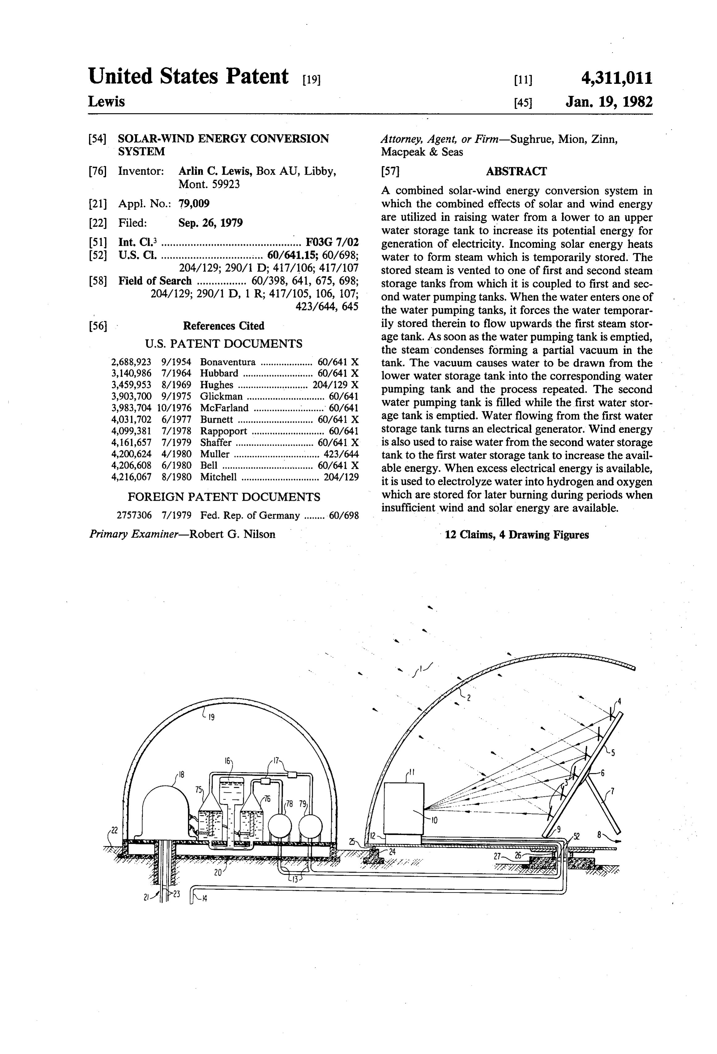
thereof for receiving water which is dumped from the bucket means as they revolve around the second pulley BRIEF. DESCRIPTION OF THE DRAWINGS means, a second endless chain member coupled to the FIG. 1 shows a cross-sectional view of the above second pulley means, and an electrical generator which 35 ground portion of a solar-wind energy conversion sys is provided input power by way of the second chain tem in accordance with the invention.
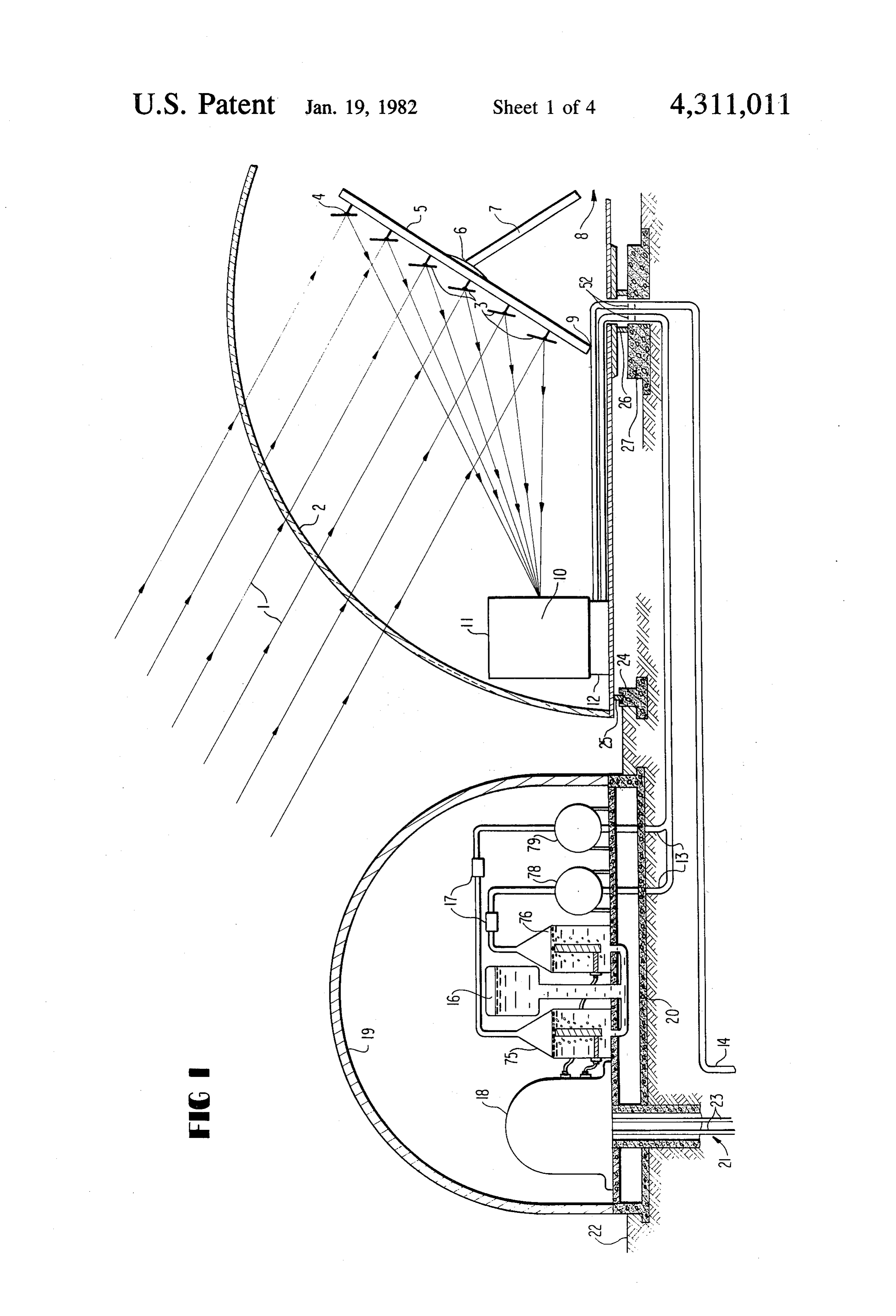
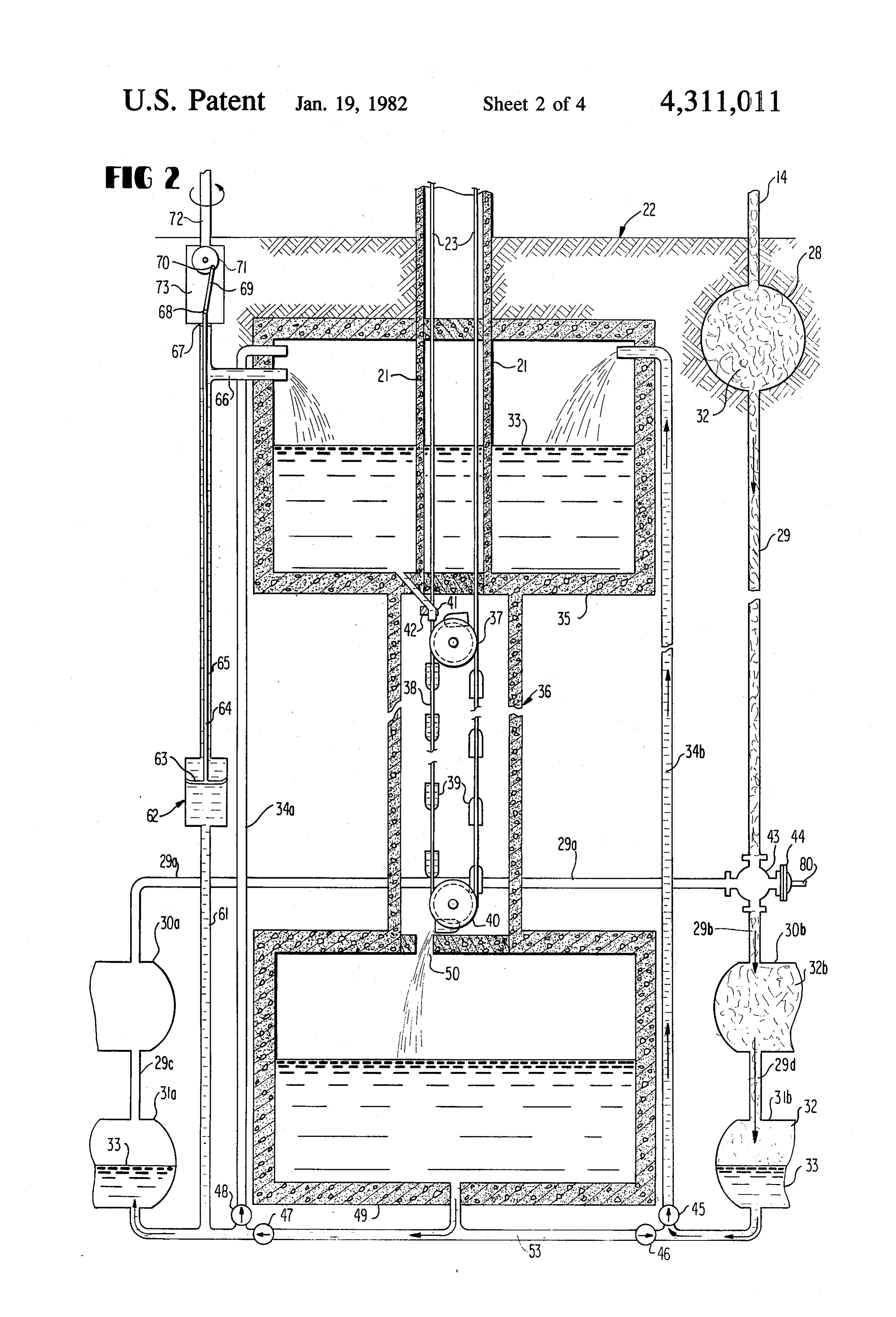
member. Also, there. may be provided means for elec FIG. 2 shows the below-ground portion of the solar trolyzing water to produce hydrogen and oxygen in . wind energy conversion system of the invention. response to the electrical current produced by the elec FIG. 3 shows a partially-cutaway view of a wind trical generator, during periods when sufficient wind 40 turbine which is utilized with the energy conversion and/or solar energy are unavailable. The hydrogen and system shown in FIGS. 1 and 2.
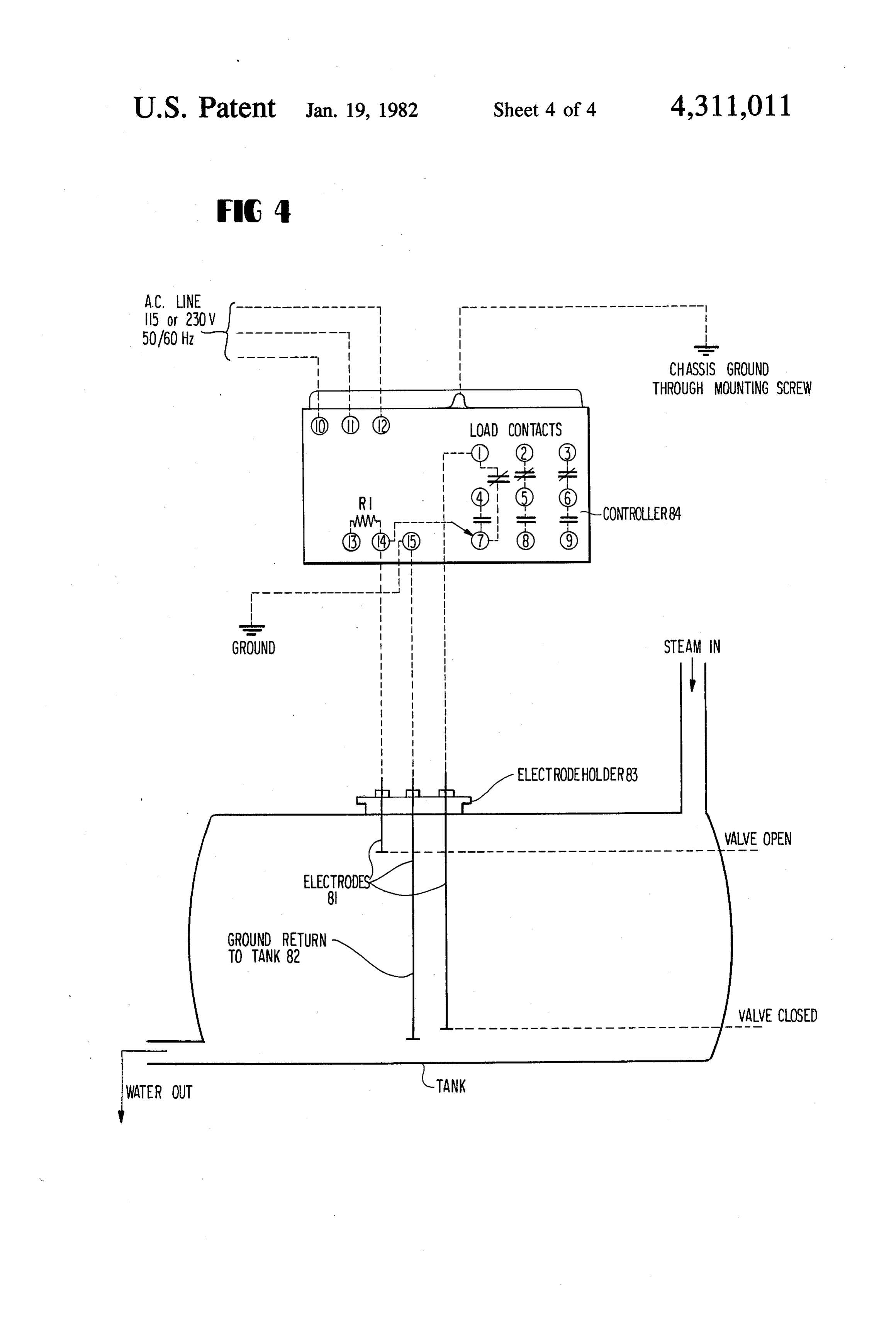
oxygen are compressed into storage tanks. A hydrogen FIG. 4 shows the valve control system used with the absorbing medium is positioned in the hydrogen storage portion of the system of the invention shown in FIG. 2. tank to reduce the pressure therein while increasing the DESCRIPTION OF THE PREFERRED hydrogen, storage capacity. The hydrogen and oxygen 45 so stored are burned at a controlled rate to heat the EMBODEMENTS boiler means to produce steam when the solar and/or Referring first to FIG. 1, there is shown therein the wind energy available falls below a predetermined mini above-ground portion of the solar-wind energy conver mum level. In regard to the production of energy from sion system of the present invention. Sun's rays 1 pass wind movement, means is provided in a preferred em 50 through semi-circle transparent dome 1 and strike mir bodiment, for producing rotational power in response rors 3 which are individually positioned upon mounts 4 to wind movement which is coupled to means for mov upon supporting frame 5 and by positioning of support ing water from the second water storage tank to the first ing member 7 attached to frame 5 through pin 6 so as to water storage tank in response to the rotational power reflect the sun's rays and to concentrate them upon a so produced. 55 focal point 10 within boiler 11. Mirrors 3 may either be In regard to another aspect of the invention, an en plane flat mirrors or may have a curved surface, if de ergy storage system may be provided which includes sired, so as to further concentrate the sun's rays onto a for electrolyzing water to produce hydrogen and oxy smaller area. Boiler 11 may be any one of a number of gen, means for compressing the hydrogen produced by well known designs having a burner 12 receiving gas the electrolyzing means into a storage tank which in from pipe 13. Steam produced by boiler 11 is conveyed cludes a hydrogen absorbing medium positioned to the underground portion of the system through pipe therein. The oxygen is compressed into a second stor 14.
age tank therefor. As related above, the hydrogen relat Boiler 11 and mirrors 3 upon frame 5 are mounted ing medium comprises preferably either a hydride of an upon circularly-shaped rotatable platform 8. Rollers 25 alloy of titanium and iron or a hydride of an alloy of 65 mounted upon the lower surface of rotatable platform 8 magnesium and nickel. The hydrogen and oxygen are at the outer periphery thereof ride upon track 24 as then recombined and burned and electricity generated platform 8 is rotated. A rotatable joint 26 supported by in response to the thermal energy thereby released. concrete member 27 supports the center section of ro
Page 8
tatable platform 8. Rotatable platform 8 is turned in water from water pumping tank 31a through one-way accordance with the movements of the sun so as to valve 48 into pipe 34a and accordingly, into upper direct the maximum available solar energy into boiler water storage tank 35. Generally, one of tanks 31a and 11. A system for producing this type of rotation is dis 31b is being filled from lower water storage tank 49 closed in the article SOLAR ENERGY (MACMIL while the other is pumping water upwards into upper LAN) PAGE96. Rotatable joints 52 are also provided water storage tank 35.
for pipes 13 and 14. When there is sufficient water within upper water Referring next to FIG. 2, steam flowing through pipe storage tank 35, water flows through spout 41 as con 14, which is a well-insulated pipe, flows into insulated trolled by trip valve 42 filling bucket members 39 con storage tank 28. Steam 32 stored in tank. 28 passes 10 nected to endless chain member 38. The added weight through pipe 29 and is directed by 3-way valve 43 to of the water in the buckets on the left side as shown in either pipe 29a or 29b to one of lower steam storage the drawings creates a large torque on pulley 37 which tanks 30a and 30b, respectively. The further operation causes the rotation thereof as well as the rotation of of these will be described below. chain member 23 connected to the other pulley (not Two relatively large water storage tanks, upper 15 shown) located upon the same shaft as pulley 37. As water storage tank 35 and lower water storage tank 49 bucket members 39 reach the bottom of pulley 40, they are provided. Both of these are preferably made of cast are tilted to the left thereby emptying the water therein concrete or a similar inexpensive material. Between through aperture 50 in the upper covered surface of upper water storage tank 35 and lower water storage lower water storage tank 49. The empty bucket mem tank 49 there is provided an endless-chain water bucket 20 bers are returned towards the upper part of pulley 37 brigade system. This includes an upper pulley 37 posi for refilling. . . .. " - tioned below the center of tank 35 and a lower pulley 40 FIG. 4 shows in diagram form the control system positioned near the top of lower tank 49. Between pull used to operate valve 43 of FIG. 2. The control system leys 37 and 40 runs an endless chain 38 to which a num includes a controller 84 connected to electrodes 81, one ber of bucket members 39 are coupled at spaced inter 25 of which is a ground return electrode 82. The end 2 of vals. Endless-chain 38 may be a link-type chain, a flexi electrodes 81 sense the level of water in tank 31. When ble metal band, a rubberized belt or the like or multiple the water level is below the upper dotted line shown in ones of one of these items. A third pulley, not shown, is the drawing, valve 43 is opened to allow steam flow coupled to the same shaft and rotates in response to the between pipe. 29 and pipe 29b. When the water falls rotation of pulley 37. A second chain 23 is coupled 30 below, the lower dotted line, the valve is closed or around this pulley. turned to the other position. Electrodes 81 are sup A spout 41 extends from the bottom of tank 35 reach ported by electrode holder 83 and are coupled to the ing towards the open mouths of the bucket members input terminals of controller. 84. Controller 84 is prefer passing around pulley 37. A trip valve 42 permits water ably a High Sensitivity Control Relay, Model B,W to flow through spout 41 only when a bucket member is 35 52-1201.00 in a NEMA -1 enclosure as manufactured positioned thereunder. : , by Fisher Controls Company of Marshalltown, Iowa. Lower water storage tank 49 includes an aperture 50 Electrode holder 83 may be an E-1 electrode holder in its upper surface for receiving water dumped by with electrode plug Model No. 04-126400 also manufac bucket members 39 as they pass around the lower por tured by Fisher Controls Company. As these units are tion of pulley 40. A pipe 53 carries water out of the commercially available and their operation well known, bottom of tank 49 through one-way valves 46 and 47 it need not be described here further. which allow water to flow only in the direction indi The discussion above is related to the production of cated by arrows. Water pumping tanks 31a and 31b are energy in the form of rotational motion via water rais coupled at the lower portion thereof to the outlets sides ing to higher level of potential energy by means of solar of valves 46 and 47. Tanks 31a and 31b are coupled by 45 power. However, a second portion of the system is the same pipes through one-way valves 48 and 45 re utilized for raising water between lower water storage spectively, to pipes 34a and 34b which extend upwards tank 49 and upper water storage tank 35 in response to into the upper portion of upper water storage tank 35. wind movement so that two means are provided for Operationally, it is first assumed that water pumping producing energy from two different natural sources so tank 31b is filled with water. At the commencement of 50 that the naturally-occurring energy available at the operations, valve 43 is opened to allow steam to pass system's location is utilized to its maximum. through pipe 29a to pipe section 29b into tank 30b. The To this end a wind turbine device, which will be. expanding steam then flows through pipe section 29d described in conjunction with FIG. 3, produces rotary into the upper portion of water pumping tank 31b. The motion in response to wind movement which rotates steam pressure forces the water out of water pumping 55 shaft 72. Threads are provided at the end of shaft 72 for tank 31b through one-way valve 45 into pipe 34d and rotating worm gear 71 as shaft 72 rotates. A follower into upper water storage tank 35. . arm 69 is pivotably connected at ends 68 and 70 respec When water storage tank 31b has been emptied of tively to lower reciprocating drive shaft. 64 and the water, valve 43 closes off the flow of steam between periphery of worm gear 71. Reciprocating drive shaft pipes 29 and 29b. As the steam in tanks 30b and 31b 60 64 passes through casing 73 which encloses the end of cools it condenses forming a partial vacuum in both shaft 72, worm gear 71 and connecting, rods 69, through tanks. As a result of the partial vacuum, water is drawn seal 67. w out of lower water storage tank 49 through one-way Reciprocating drive shaft 64 extends through the valve 46 into water pumping tank 31b thereby refilling center of pipe 65 to pumping section 62 at which its it. 65 lower end is coupled to piston 63. Piston.63 is con While tank 31b is being refilled, valve 43 directs the structed with well known principles and includes the flow of steam through pipe 29 to pipe 29a and into sealing member at the outer periphery thereof and a lower steam storage tank 30a. This, in turn, forces the foot valve in intermediate portions. The lower end of
Page 9
pumping section 62 is coupled through pipe 61 to pipe a second water storage tank positioned beneath said 53 or to any location from which water from tank 49 first water storage tank; can be pumped. If preferred, a separate connection to first and second lower steam storage tanks; the lower portion of tank 49 can be provided. valve means for selectively coupling said primary In operation, the rotational shaft 72 causes worm gear steam storage tank to one of said first and second 71 to rotate which produces reciprocating movement in lower steam storage tanks; reciprocating drive rod 64 via connecting rod 69. Re first and second water pumping tanks, said first and ciprocating drive rod 64 operates pump section 62 to second water pumping tanks being respectively thereby pump water from lower water storage tank 49 coupled to said first and second lower steam stor through pipes 61 and 65 through outlet 66 into the 10 age tanks;
upper portion of upper water storage tank 35. The po first coupling means for coupling said first and second tential energy of the system is thereby increased in lower steam storage tanks to said second water response to energy generated by wind movement as storage tanks, said first coupling means having well as by action of solar energy. means for permitting water flow only in the direc Referring now back to FIG. 1, endless chain 23 is 15 tion of said first and second lower steam storage coupled to electrical generator 18 which operates to tanks; . produce electricity in response to rotation of endless second coupling means for coupling said first and chain. 23. A number of well-known devices may be used second lower steam storage tanks to said first water for generator 18. The generator 18 is mounted on a storage tanks, said second coupling means having concrete slab 20. A governor for controlling the rate of 20 means for permitting water flow only in the direc rotation of generator 18 may be provided if desired. In tion of said first water storage tank; another embodiment, endless chain 23 is coupled to a first pulley means positioned in a region beneath said hydraulic pump which in turn is coupled to a hydraulic first water storage tank; motor which operates the generator. A compensator second pulley means positioned in a region above said valve located between the hydraulic pump and hydrau 25 second water storage tank; lic motor can then be used to perform the function of a first endless chain member running between said the governor. As shown in FIG. 1, the fuel for the first and second pulley means; burner 12 is supplied by hydrogen and oxygen gas de a plurality of bucket means coupled to said chain rived by electrolyzing water. Water from tank 16 is member at spaced intervals; supplied to a hydrogen electrolysis compartment 75 and 30 water spout means for moving water from said first oxygen electrolysis compartment 76. Both compart water storage tank to said bucket means in the ments receive current from the generator 18 and pro vicinity of said first pulley means; duce a gas output compressed by compressor 17. Tanks said second water storage tank having an aperture in 78 and 79 store the compressed hydrogen and the com the upper portion thereof for receiving water from pressed oxygen and supply it to pipe 13. Storage tank 79 35 said bucket means;
contains a hydrogen absorbing material such as a hy a second endless chain member coupled to said sec dride of an alloy of titanium, iron, magnesium or nickel ond pulley means; and as is well known in this art. an electrical generator, said second chain member With reference to FIG. 3, there is shown a partially being coupled to provide input operating power to cut-away view of a wind turbine which may be utilized 40 said electrical generator. with the energy conversions system shown in FIGS. 1 2. The solar energy conversion system of claim 1 and 2. The device includes two interconnected scoops further comprising:
or funnels including input wind scoop 99 and larger means for electrolyzing water to produce hydrogen output cone 94. The incoming high pressure air enter at and oxygen therefrom in response to electrical 91 and is concentrated by the right-hand portion of 45 current produced by said electrical generator; scoop 99. Its velocity is thereby increased by the point means for compressing said hydrogen and oxygen; at which it strikes turbine wheel 92. Turbine wheel 92 is a storage tank for receiving the compressed hydro coupled through a turbine shaft to gears 95, the lower gen;
one of which is coupled directly to downshaft 72. The a hydrogen absorbing medium within said tank for entire device rotates upon bearing 96 mounted upon the 50 receiving the compressed hydrogen; top of mast 97. Shaft 72 extends downward through a storage tank for receiving the compressed oxygen; mast 97 to the portion of the apparatus shown in FIG. 2. means for burning at a controlled rate hydrogen and Guy wires 98 may be employed to support mast 97. oxygen from said storage tanks for receiving the This completes the description of the preferred em compressed hydrogen and oxygen to heat said bodiments of the invention. Although preferred em 55 boiler means.
bodiments have been described, it is believed that nu 3. The solar energy conversion system of claim 2 merous modifications and alterations thereto would be wherein said hydrogen absorbing medium comprises a apparent to one having ordinary skill in the art without hydride of an alloy of titanium and iron. departing from the spirit and scope of the invention. 4. The solar energy conversion system of claim 2 What is claimed is: 60 wherein said hydrogen absorbing material comprises a 1. A solar energy conversion system comprising: hydride of an alloy of magnesium and nickel. boiler means for producing steam in response to solar 5. The solar energy conversion system of claim 1 energy; further comprising:
means for directing solar rays towards a predeter means for producing rotational power from wind mined portion of said boiler means; 65 movement; and a primary steam storage tank for storing steam pro means for moving water from said second water stor duced by said boiler means; age tank to said first water storage tank in response a first water storage tank; to said rotational power.
Page 10
6. In combination: means for electrolyzing water in response to said boiler means responsive to input solar energy for electrical energy;
producing steam; means for storing hydrogen produced by said electro means for producing kinetic mechanical energy in lyzing means; and response to wind movement; means for storing oxygen produced by said electro means receiving said steam and producing kinetic lyzing means.
8. The solar energy conversion system of claim 7 mechanical energy; wherein said hydrogen storing means comprises: means for producing electrical energy in response to a tank; and both said kinetic mechanical energy produced in O a gas absorbing medium positioned within said tank. response to input solar energy and produced in 9. The solar energy conversion system of claim 8 response to said wind movement; wherein said gas absorbing medium comprises a hy means for storing energy produced in response to said dride of an alloy of titanium and iron. electrical energy, said means for producing electri 10. The solar energy conversion system of claim 9 15 wherein said gas absorbing medium comprises a hy cal energy also producing electrical energy in re dride of an alloy of magnesium and nickel. sponse to energy stored by said storing means; 11. The solar energy conversion system of claim 6 heating means receiving the output of said means for further comprising:
storing to heat said boiler when the solar energy said means responsive to wind movement moves received by said boiler means falls below a prede 20 water from said second tank to said first tank in termined level; response to wind movement. means for directing solar energy towards and for 12. The solar energy conversion system of claim 6 concentrating solar energy at said boiler; wherein said means for moving water from said second a first water storage tank; tank to said first tank in response to said steam com a second water storage tank, said second water stor 25 prises:
age tank being at a lower position than said first a water pumping tank having a first port in an upper water storage tank; portion thereof and a second port in a lower por said means receiving steam comprising means for tion thereof;
moving water from said second water storage tank means for coupling said first port to said boiler means to said first water storage tank in response to steam 30 for receiving steam therefrom; produced by said boiler; means for coupling said second port to said first tank, means for returning water from said first water stor including therein means for permitting water flow only in the direction of said first tank; and age tank to said second water storage tank; and means for coupling said second port to said second wherein electricity is generated in response to move 35 tank including therein means for permitting water ment of water by said returning means. flow only in the direction of said water pumping 7. The solar energy conversion system of claim 6 tank.
wherein said energy storing means comprises: ak : k
Provenance
- Collection
- Cited prior art
- Original PDF
- patentimages.storage.googleapis.com →
- Filed
- 1979-09-26
- Pages
- 10
- Method
- pdftotext (the PDF's own text layer) + pdftoppm 300dpi page scans
- Source
- Google Patents bibliographic record
- Granted
- 1982-01-19
- Inventors
- Arlin C. Lewis
- Transcribed from
- patentimages.storage.googleapis.com →