patent · US3101592
Closed power generating system
27 August 1963
Page 1 — bibliographic record
Aug. 27, 1963 A. E. ROBERTSON ETAL 3,101,592
CLOSED POWER GENERATING SYSTEM
Filed Jan. 16, 196l 3. Sheets-Sheet
oxYGaAv sovece,
Ayydeogaw
Gatwa earae
SNSSANSN
281E O 1-2-2. t-t -
INVENTORS
Voseae, Zamryce
Page 2
Drawing sheet — no readable text.
Page 3
Drawing sheet — no readable text.
Page 4
United States Patent Office Patented Aug. 27, 1963
ed overboard, thereby eliminating any wake and effecting 3,101,592 substantial fuel savings.
CLOSED POWER GENERATING SYSTEM A further object of the present invention is to provide a Anthony E. Robertson, Willoughby, Ohio, and Joseph T. power plant for torpedo and Submarine propulsion where Hamrick, Roanoke, Va., assignors to Thompson Ranto
Wooldridge Inc., Cleveland, Ohio, a corporation of in hydrogen and oxygen are burned to produce Super heated steam, the hydrogen and/or oxygen being pro
Ohio
Filed Jan. 16, 1961, Ser. No. 83,000 vided by adding condensate water to Water reactive chemi
Other objects and advantages of the invention will be
The present invention relates broadly to power plants 10 come, more apparent during the course of the following and is more particularly concerned with a new and in description, particularly when taken in connection with proved power plant for under water use featuring as the the accompanying drawings.
energy source a chemical system productive of the in In the drawings, wherein like numerals designate like portant advantages of essential absence of exhaust noises parts throughout the same:
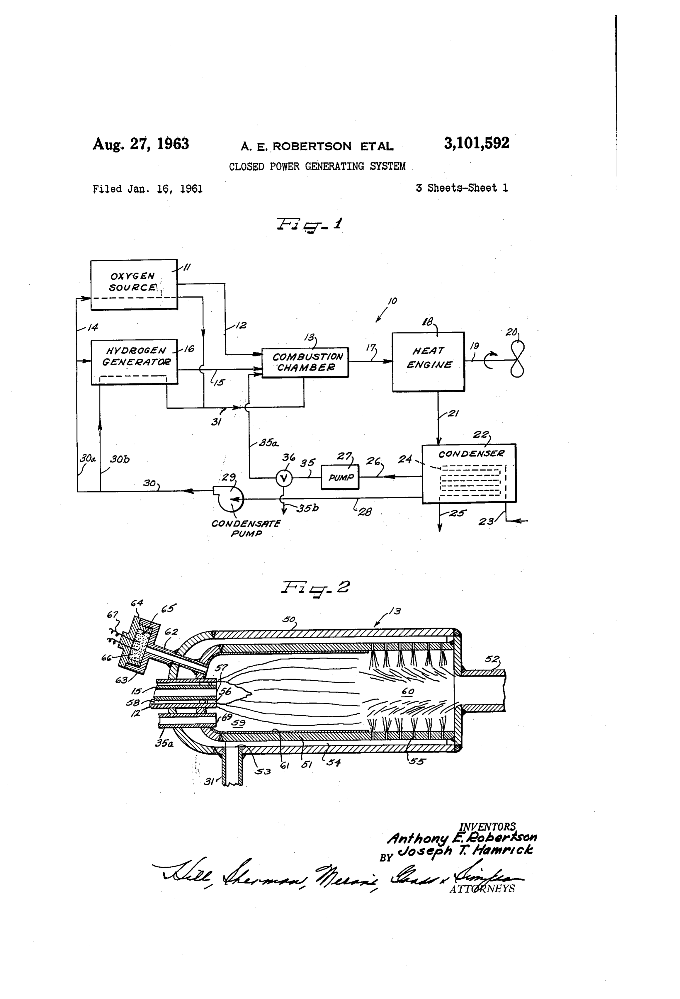
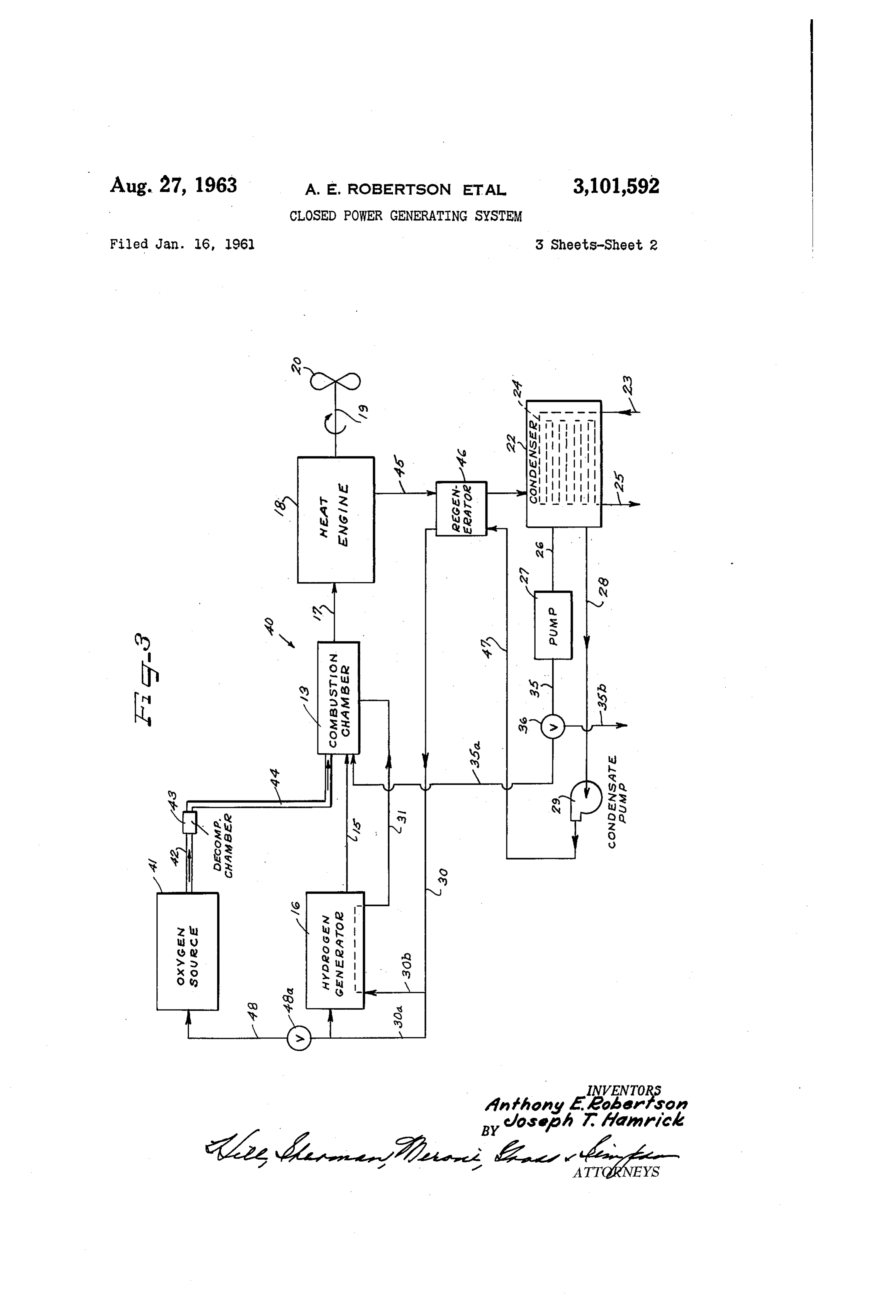
and a power output independent of operating depth. 15 FIGURE 1 is a schematic diagram of a power plant While other applications may exist, the power plant system embodying the novel concepts of this invention; of this invention is productive of especially advantageous FIGURE 2 is a sectional view of one form of combus results when employed for submarine and torpedo pro tion chamber which can be utilized in practice of this pulsion, and the description will be directed particularly invention;
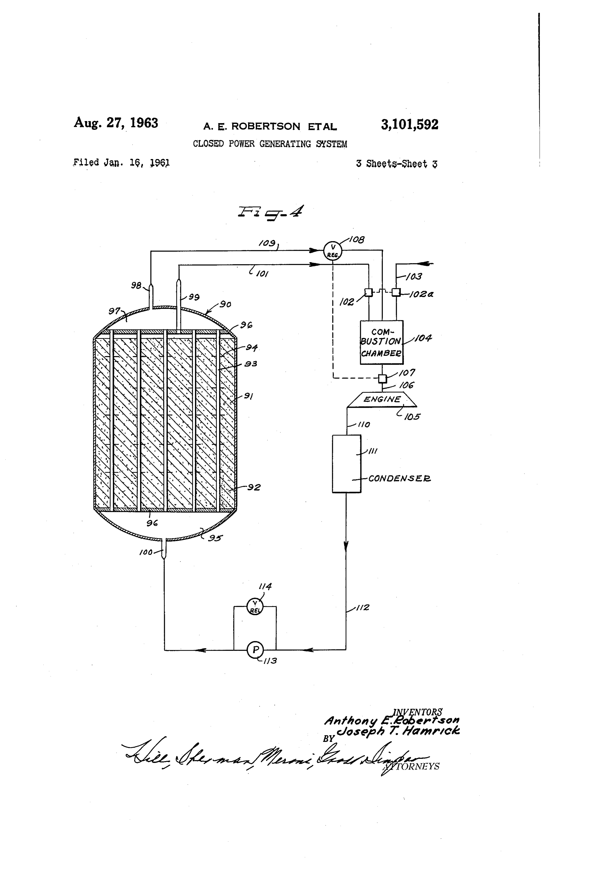
to a power plant for deep running torpedoes. As is 20, FIGURE 3 is a schematic diagram of another power. known, the basic problem in torpedo power plants is to. plant system incorporating the instant teachings; and obtain maximum power for a minimum in Weight and FIGURE 4 is a more or less diagrammatic view of space. Since torpedoes are relatively short range de an exemplary form of hydrogen generator which may be vices, it is required that the power plant have a high power used in the systems of FIGURES 1 and 3, and further output for a relatively short time. Battery driven elec 25 showing the connections therefrom to certain other ele ments of the power plant system.
tric motors and heat engines, both of the turbine and piston type, have been widely used for torpedo propulsion. Briefly stated, the present invention is directed toward In addition, fuel cells and atomic reactors have been con a power plant system for under water applications fea sidered for this purpose. turing supplying gaseous hydrogen and oxygen to a con However, within the present state of the art, electric 30 bustion chamber from suitable sources, which in the case of oxygen may be hydrogen peroxide to be catalytically systems cannot meet the speed and range requirements of advanced design torpedoes due to the relatively high decomposed or a metallic peroxide or a Superoxide that is weight of batteries and electric motors. The same situa hand, reactive with water. The hydrogen source, on the other tion appears to prevail with respect to fuel cells, in spite may be a water reactive compound and exemplary of their relatively high efficiency of conversion of chemi 35 thereof are diborane and certain metal hydrides and boro cal to electrical energy. Atomic powered torpedoes, on hydrides. Within the combustion chamber combustion is the other hand, could be built to have the required per initiated, the hydrogen essentially completely oxidized formance, at least in the larger sizes, but the resulting and the combustion products cooled to approximately structure can be anticipated to be relatively cumbersome 40 1200° F. by the injection of liquid water or steam. and costly. The superheated steam from the combustion chamber It is for these reasons that heat engines appear to hold is expanded in a heat engine and ported to a condenser the greatest promise as the foremost contenders for full preferably cooled by sea water. The condensate Water filling the power plant requirements of torpedoes and Sub is then directed to the combustion chamber for cooling marines for the foreseeable future. However, present 45 purposes, producing additional superheated steam, and if heat engines for torpedoes have the basic problem of a desired, a portion of the condensate water can be added to drastic reduction in power as the depth increases, due water reactive chemicals for producing hydrogen and/or largely to the increase in exhaust pressure and the result oxygen. Most preferably, any non-condensable gases are ing loss in cyclic efficiency. In addition, for acoustic directed to the combustion chamber. It may now be homing torpedoes the noise generated by the exhaust con 50 noted that there is herein provided a closed cycle in which stitutes an undesirable contribution to the torpedo self essentially all of the working fluids are condensed and any noise. non-condensibles are burned, so that no gases are dis It is accordingly an important aim of the present in charged overboard. The power output of the disclosed vention to provide a power plant for under Water use em system is not dependent upon the operating depth, ex ploying either a semi-closed or fully closed cycle in which 55 haust noises and wake are essentially entirely eliminated, preferably all of the working fluids are condensed and and substantial fuel savings are effected. nothing is exhausted, thereby producing a power output In the past various types of turbines and piston engines independent of operating depth and further featuring an have been used to drive torpedoes, and generally speaking, essential absence of exhaust noises. all of these systems have exhausted to ambient pressures. Another object of this invention lies in the provision of 60 While this is satisfactory as long as the ambient pressure a deep operating power plant having as one feature thereof is relatively small, with increasing ambient pressure a typi burning hydrogen and oxygen to produce super-heated, cal system wherein the heat engine uses the gas produced steam which is expanded in a heat engine and then con by the burning of a solid grain propellant shows, for a densed to water, producing a cycle independent of am given propellant consumption rate, a rapid decrease in bient pressure. power and a corresponding increase in specific fuel con Another object of the instant invention is to produce a 65 sumption. However, with the instant chemical propulsion power plant of the foregoing character, additionally fea system in which essentially all of the combustion prod turing use of the condensed water to cool the combustion lucts are condensible, performance can be made com chamber by spraying water therein to produce additional pletely independent of the operating depth. Superheated steam for use in the heat engine. The hydrogen and the oxygen may be stored as com Still another object of this invention lies in the pro 70 pressed gases, or in the form of chemical compounds. vision of a power plant wherein the non-condensible gases By the proper choice of chemicals, there is produced large are directed to the combustion chamber, rather than port amounts of the desired gases per unit of weight and
Page 5
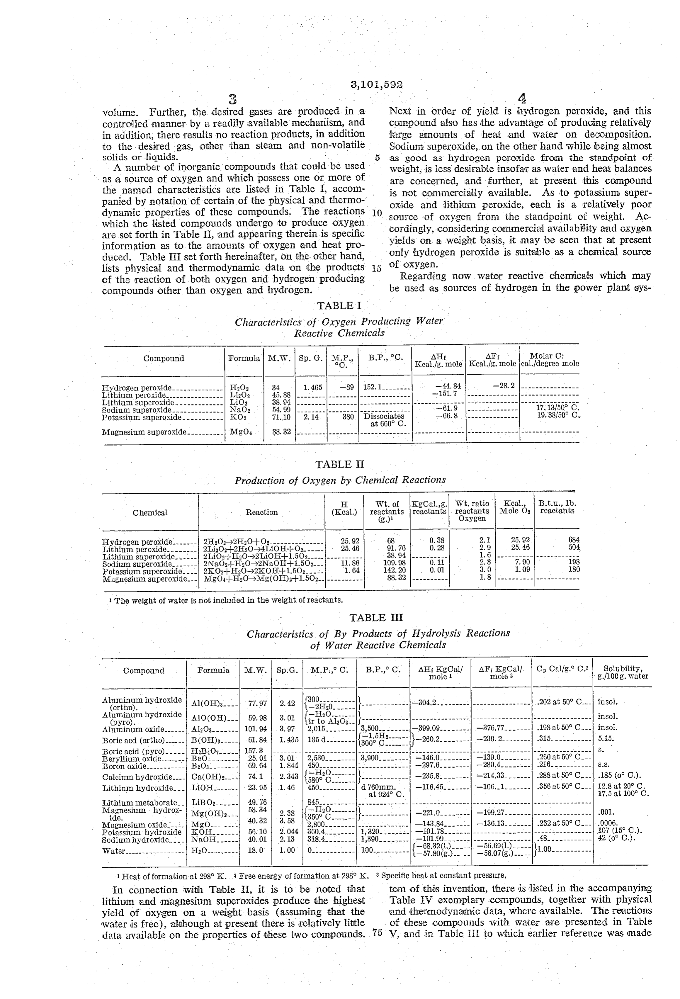
voiume. Further, the desired gases are produced in a Next in order of yield is hydrogen peroxide, and this controlled manner by a readily available mechanism, and compound also has the advantage of producing relatively in addition, there results no reaction products, in addition large amounts of heat and water on decomposition.
to the desired gas, other than steam and non-volatile Sodium. Superoxide, on the other hand while being almost solids or liquids. as good as hydrogen peroxide from the standpoint of
A number of inorganic compounds that could be used Weight, is less desirable insofar as water and heat balances as a source of oxygen and which possess one or more of are concerned, and further, at present this compound the named characteristics are listed in Table , accom is not commercially available. As to potassium super panied by notation of certain of the physical and thermo oxide and lithium peroxide, each is a relatively poor dynamic properties of these compounds. The reactions O Source of oxygen from the standpoint of weight. Ac which the listed compounds undergo to produce oxygen cordingly, considering commercial availability and oxygen are set forth in Table II, and appearing therein is specific yields on a weight basis, it may be seen that at present information as to the amounts of oxygen and heat pro only hydrogen peroxide is suitable as a chemical source duced. Table III set forth hereinafter, on the other hand, of oxygen.
lists physical and thermodynamic data on the products cf the reaction of both oxygen and hydrogen producing Regarding now water reactive chemicals which may compounds other than oxygen and hydrogen. be used as sources of hydrogen in the power plant sys
TABLE
Characteristics of Oxygen Producting Water
Reactive Chemicals
B.P., C. AHf AFf Molar C:
Kcal.fg. mole Kcal.fg. mole calf degree mole
Hydrogen peroxide-------------- FI2O2 34 - 1.465 -89 152.1-------- - 44.84
Lithium peroxide---------------- Li2O2 45.88 --------|--
Lithium superoxide - LiO2 38.94 -------
Sodium superoxide. NaO2 54.99 ------------------------------ 17, 13150° C.
Potassium Superoxide ----------- KO2 7.10 2.14 19.38,50° C.
Magnesium Superoxide---------- MgO4 88.32 --------------------------------------------------------------------------
TABLE
Production of Oxygen by Chemical Reactions
H Wt. of Kgoal.g. Wit. ratio Kcal., B.t.u., Ib.
Chemical Reaction (Kcal.) reactants (g.) reactants reactants
Oxygen Mole O reactants
Hydrogen peroxide. 2H2O-2H20+O----------- 25.92 68 - 0.38 2. 25.92 684 Lithiumperoxide- 2LiO-2H2O-4LiOH-I-O- 25.46 91.76 0.28 2.9 25.46 504 Lithium superoxide- 2LiO2- HO-X2LiOH--1.5O2--------------- 38.94 ---------- 1.6---------------------- Sodium. Superoxide-...---- 2NaO2-HO-X2NaOH--.5O2--- .86 109.98 0. 2.3 7. 90 193 Potassium superoxide----| 2KO-H2O-2KOE-1.50---. 1.64 42.20 0.01 3.0 1.09 80 Magnesium superoxide--- MgO-H-HO-Mg(OH)2-1-1.5O2------------ 88.32 ---------- l.8---------------------- 1 The weight of water is not included in the weight of reactants.
TABLE I
Characteristics of By Products of Hydrolysis Reactions - of Water Reactive Chemicals
Compound Formula M.W. Sp.G. I. M.P., C. B.P., C. AIf Kgoal? AF. KgCalf C Cal/g.8 C.3 Solubility, - mole 1 Inole 2 g./100g. water
Ali Rin hydrosia Al(OH)3---- 77.97 2.42 E.:---- }------------- -304.2------------------------- .202 at 50 C--- insol.
uminum hydroxide 2V------- (pyro). AlO(OH)- 59.98 3.01. tr to Aloi?------------------------------------------------------------- insol.
Aluminum oxide------ Al2O3------- 101.94 3.97 2,015.-- - 3,500-------- -399.09.-------- -376.77------- 198 at 50° C. insol.
Boric acd (ortho)-----. B(OH)3.----- , 61.84 (36. }-260.2. . . . - W - - -230. 2.-------- 315----------- 5.5. Boric acid (pyro)----- H2BiO7----- 157.8 --------------------------------------------------------------------|---------------- S.
Beryllium oxide.------- BeO-- 25.0 -146.0-------- - .260 at 50° C. -- Boron oxide----- -- B2O3- - 69.64 -297.6-------- 216----------- S.S. Calcium hydroxide---- Ca(OH)2.--- 74.1 2.343 K------------- -235.8-------- .288 at 50° C. -- .185 (o C.). Lithium hydroxide--- LiOH------- 23.95 -116.45------- 356 at 50° C -- 12.8 at 20° C.
E. Italia. - LiBO2------ : 3. - - -- - - - - - - -- -- - - - - - - - - - - - - - - - - - - - - - - - - - - - - - - -- - - - - - - - - - - - - - -- - - - -
ide. Mg(OH)2- . -221.0-------- .001. Magnesium oxide. MgO------. -43.84------- .0006. lotassium hydroxide KOH- 56.10 -101.78---------- 107 (15° C.). Sodium hydroxide. -- NaOH- 40.01 -, -101.99.------- - 42 (o' C.). Water----------------- H2O----- 18.0 -KS).
1 Heat of formation at 298 K. 2 Free energy of formation at 298 K. 3 Specific heat at constant pressure.
In connection with Table II, it is to be noted that tem of this invention, there is listed in the accompanying lithium and magnesium superoxides produce the highest Table IV exemplary compounds, together with physical yield of oxygen on a weight basis (assuming that the and thermodynamic data, where available. The reactions water is free), although at present there is relatively little of these compounds with water are presented in Table data available on the properties of these two compounds. 75 V, and in Table II to which earlier reference was made
Page 6
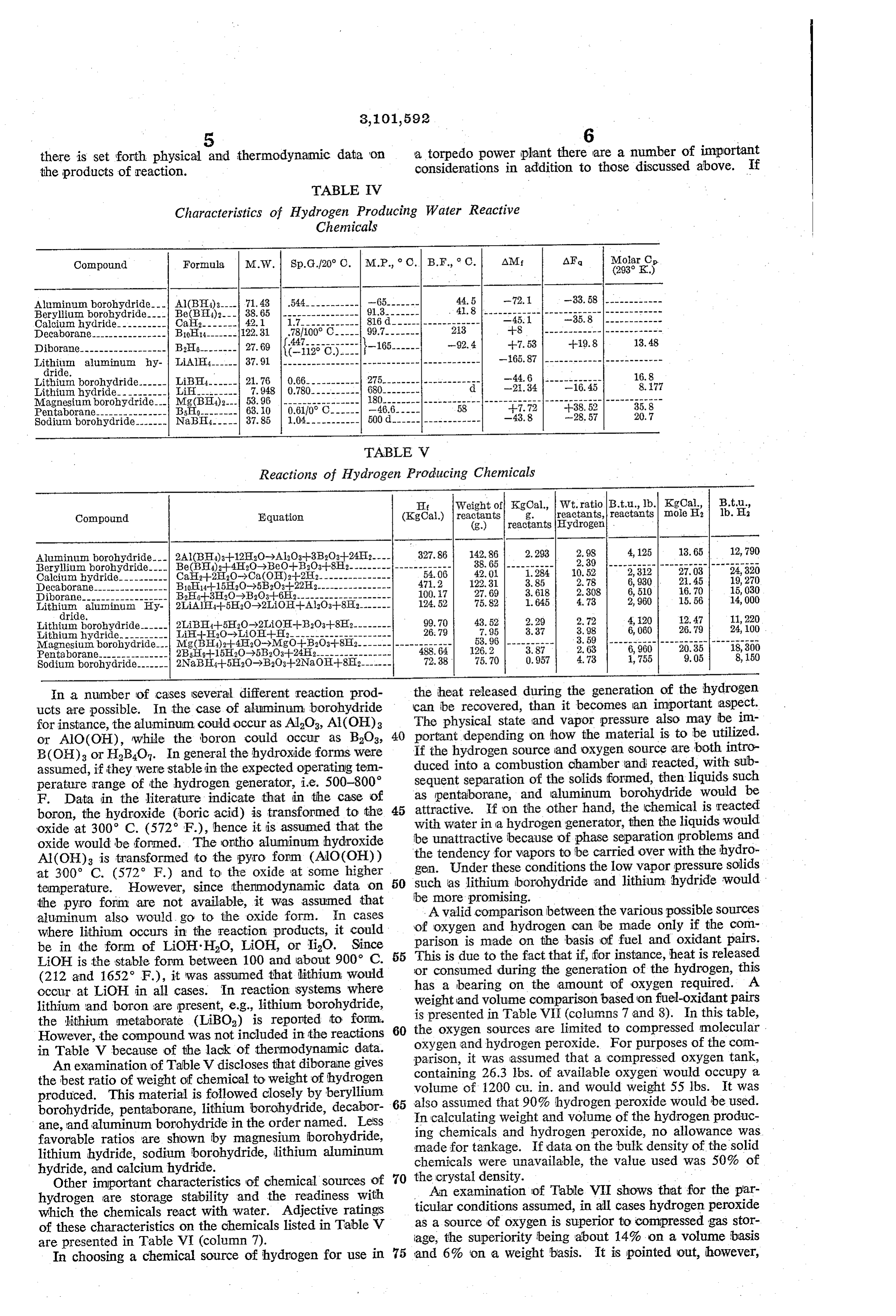
there is set forth physical and thermodynamic data on a torpedo power plant there are a number of important the products of reaction. considerations in addition to those discussed above. If
TABLE IV
Characteristics of Hydrogen Producing Water Reactive
Chemicals
Compound Formula M.W. Sp.G120° C. M.P., C. B.F., C. AMIf
Aluminum borohydride. Al(BH)3. 71.43 44.5 -72.
Beryllium borohydridie. --. Be(BH4)2- -38. 65 4.8---------------------------- Calcium hydride---------- CaF2------- 42.1 1.7------------ 816d------------------ -45.1
Decaborane--------- B10H14------- 122.31 .78/100° C----- 99. 213 --8
Diborane------------------ B2H6-------- 27.69 Kisso). I-165...... --92.4 -7.53
Lili aluminum hy- LiAlH4------ 37.91 -65.87
Cle.
Lithium borohydride------ LiBI4------ 21.76 -44.6
Lithium hydride---------- LiH--------- 7.948 -2.34 - Magnesium borohydride--- Mg(BH4)2-. 53.96 ---------------- 180-------------------------------- - - - - - - - - - - - - - - - - - - - - - - - - Pentaborane--------------- Bisho-------- 63. 10 0.6110°C.-------46.6----- 58 --7.72 --38.52 35.8 Sodium borohydride-----. NaBH4----- 37.85 1.04----------- 500d.----------------- -43.8 -28.57 20.7
TABLE V
Reactions of Hydrogen Producing Chemicals
EIt Weight of Kgoal., Wt, ratio B.t.u., lb. KgCal. B.tu,
Compound Equation (KgCal.) reactants 3. reactants, reactants mole H2 lb. I (g.) reactants Hydrogen
Aluminum borohydride--- 2Al(BH4)3--12H2O->Al2O3-3B2O3-24H---- 327.86 42.86 2.293 2.98 4, 125 13.65 12,790 Beryllium borohydride Be(BIA)--42O->BeO--B2O3--8H2--------------------- 38.65 ---------- 2.89 ------------------------------ Calcium hydride.----- Ca2-2H2O->Ca(OH)2-2H2- 54.06 42.01 1.284 0.52 2,312 27,03 24, 320 Decaborane---- B1014-15EIO-5B2O3--22H2-- 471.2 22.31 3.85 2.78 6,930 2.45 19,270 Diborane------------------ B2H6-3EI2O->B2O3-6E2------------- -- 100.17 27.69 3. 618 2.308 6, 510 16.70 15, 030 Lith aluminum Hy- 2LiAlH4-H5H2O->2LiOH-Al2O3--82------- 124.52 75.82 1.645 4.73 2,960 15.56 14,000
Lithium borohydride------ 2LiBEIA-5H2O-2TiOE--B2O3-8H2-------- 99.70 43.52 2.29 2.72 4, 20 2.47 11,220 Lithium hydride.---- -- Lih-H2O >LiOH-H2--------- 26.79 7.95 3.37 3.98 6,060 26.79 24, 100 Magnesium borohydri - MgCBH4)2-4E2O->MgO-H-B2O3--8Ei2------------------- 53.96 ---------- 3.59 ------------------------------ Pentaborane.-------------- 2B5Hg--15H2O->5B2O3-24H------ 488.64 26.2 3.87 2.63 6,960 20.35 18,300 Sodium borohydride------- 2NaBH4-5H2O->B2O3-1-2NaOE--82------ 72.38 75.70 0.957 4.73 1,755 9,05 8, 150
in a number of cases several different reaction prod the heat released during the generation of the hydrogen ucts are possible. In the case of aluminum borohydride can be recovered, than it becomes an important aspect.
for instance, the aluminum could occur as AlaO3, Al(OH)3 40 The physical state and vapor pressure also may be im portant depending on how the material is to be utilized.
or AlO(OH), while the boron could occur as BOs, If the hydrogen source and oxygen source are both intro
B(OH)3 or HBO. In general the hydroxide forms were assumed, if they were stable in the expected operating tem duced into a combustion chamber and reacted, with Sub perature range of the hydrogen generator, i.e. 500-800 sequent separation of the solids formed, then liquids such
F. Data in the literature indicate that in the case of as pentaborane, and aluminum borohydride would be attractive. If on the other hand, the chemical is reacted boron, the hydroxide (boric acid) is transformed to the 45 with oxide at 300° C. (572 F.), hence it is assumed that the water in a hydrogen generator, then the liquids would oxide would be formed. The ortho aluminum hydroxide be unattractive because of phase separation problems and
Al(OH)3 is transformed to the pyro form (AlO(OH)) the tendency for vapors to be carried over with the hydro at 300° C. (572 F.) and to the oxide at some higher gen. Under these conditions the low vapor pressure solids temperature. However, since thermodynamic data on 50 such be as lithium borohydride and lithium hydride would more promising.
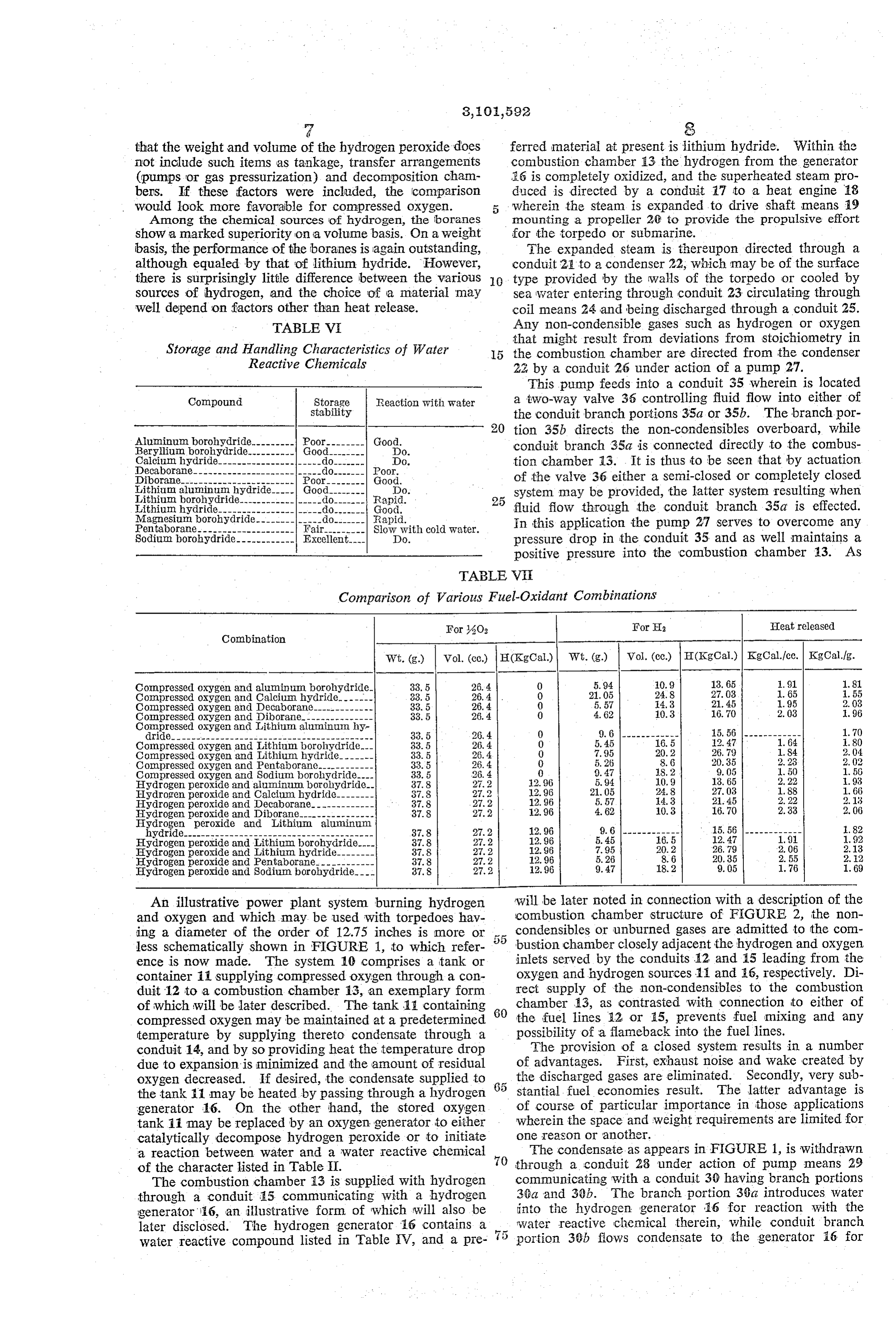
the pyro form are not available, it was assumed that A valid comparison between the various possible sources aluminum also would go to the oxide form. In cases of oxygen and hydrogen can be made only if the com where lithium occurs in the reaction products, it could parison is made on the basis of fuel and oxidant pairs.
be in the form of LiOH-HO, LiOH, or iO. Since 55 This is due to the fact that if, for instance, heat is released LiOH is the stable form between 100 and about 900° C.
(212 and 1652. F.), it was assumed that lithium would 'or consumed during the generation of the hydrogen, this occur at LiOH in all cases. In reaction systems where has a bearing on the amount of oxygen required. A lithium and boron are present, e.g., lithium borohydride, weight and volume comparison based on fuel-oxidant pairs the lithium metaborate (LiBO) is reported to form. 60 the is presented in Table VI (columns 7 and 8). In this table,
However, the compound was not included in the reactions oxygen sources are limited to compressed molecular.
in Table V because of the lack of thermodynamic data. oxygen and hydrogen peroxide. For purposes of the com
An examination of Table V discloses that diboraine gives parison, it was assumed that a compressed oxygen tank, containing 26.3 lbs. of available oxygen would occupy a the best ratio of weight of chemical to weight of hydrogen Volume produced. This material is followed closely by beryllium of 1200 cu. in. and would weight 55 lbs. It was borohydride, pentaborane, lithium borohydride, decabor 65 also assumed that 90% hydrogen peroxide would be used.
In calculating weight and volume of the hydrogen produc ane, and aluminum borohydride in the order named. LeSS ing chemicals and hydrogen peroxide, no allowance was favorable ratios are shown by magnesium borohydride, made for tankage. If data on the bulk density of the solid lithium hydride, sodium borohydride, lithium aluminum chemicals were unavailable, the value used was 50% of hydride, and calcium hydride.
Other important characteristics of chemical sources of 70 the crystal density.
hydrogen are storage stability and the readiness with An examination of Table VII shows that for the par which the chemicals react with water. Adjective ratings ticular conditions assumed, in all cases hydrogen peroxide of these characteristics on the chemicals listed in Table V as a Source of oxygen is superior to compressed gas stor are presented in Table VI (column 7). age, the Superiority being about 14% on a volume basis
In choosing a chemical source of hydrogen for use in 75 and 6% on a weight basis. It is pointed out, however,
Page 7
that the weight and volume of the hydrogen peroxide does ferred material at present is lithium hydride. Within the not include such items as tankage, transfer arrangements combustion chamber 13 the hydrogen from the generator (pumps or gas pressurization) and decomposition cham 26 is completely oxidized, and the Superheated Steam pro bers. If these factors were included, the comparison duced is directed by a conduit 17 to a heat engine i8 would look more favorable for compressed oxygen. 5 wherein the steam is expanded to drive shaft means 19 Among the chemical sources of hydrogen, the boranes mounting a propeller 26 to provide the propulsive effort show a marked superiority on a volume basis. On a weight for the torpedo or Submarine.
basis, the performance of the boranes is again outstanding, The expanded steam is thereupon directed through a although equaled by that of lithium hydride. However, conduit 2, to a condenser 22, which may be of the surface there is surprisingly little difference between the various type provided by the walls of the torpedo or cooled by sources of hydrogen, and the choice of a material may sea water entering through conduit 23 circulating through well depend on factors other than heat release. coil means 24 and being discharged through a conduit 25. TABLE VI Any non-condensible gases Such as hydrogen or OXygen that might result from deviations from stoichiometry in
Storage and gling 2.attritics of Water 15 the combustion chamber are directed from the condenSer edictive Chief iCS 22 by a conduit 26 under action of a pump 27.
This pump feeds into a conduit 35 wherein is located
Compound Storage Reaction with Water a two-way valve 36 controlling fluid flow into either of stability the conduit branch portions 35a or 35b. The branch por
Aluminum borohydrid 20 tion 35b directs the non-condensibles overboard, while fSEI Poor-------- Good. conduit branch 35a is connected directly to the combus Calcium hydride
Decaborane tion chamber 13. s It is thus to be seen that by actuation
Diborane- of the valve 36 either a semi-closed or completely closed Lithium al a Lithium borohydride 25 system may be provided, the latter System resulting when E. YES s --- fluid flow through the conduit branch 35a is effected. Eborohydride- In this application the pump 27 serves to overcome any Sodium borohydride------------ Excellent---- DO. pressure drop in the conduit 35 and as well maintains a positive pressure into the combustion chamber 13. As
TABLE VE
Comparison of Various Fuel-Oxidant Combinations
For -6O2 Fort Heat released
Combination
Wit. (g) Vol. (cc) H(Kgoal.) Wt. (g) Vol. (c.c.) H(KgCal.) KgCal.fcc. Kgoal.fg.
Compressed oxygen and aluminum borohydride. 33.5 26.4 O 5.94 0.9 3.65 91 1.81 Compressed oxygen and Calcium hydride----. 33.5 26.4 O 21.05 24.8 27.03 1.65 55 Compressed oxygen and Decaborane---- 33.5 26.4 0 5.57 4.3 21.45 1.95 2.03 Compressed oxygen and Diborane.-------------- 33.5 26.4 0 4.62 0.3 16.70 2.03 1.96 Compressed oxygen and Lithium aluminum hy dride------------------------------------------ 33.5 26, 4 0. 9.61------------ 15.56 ------------ 1.70 Compressed oxygen and Lithium borohydride.-- 33.5 26, 4. O 5.45 6.5 2.47 1.64 80 Compressed oxygen and Lithium hydride- 33.5 26.4 O 7.95 20.2 26.9 S4 2.04 Compressed oxygen and Pentaborane.------ 33.5 26.4 O 5.26 8.6 20.35 2.23 2.02 Compressed oxygen and Sodium borohydride... 33.5 28.4 9.47 S.2 9.05 1.50 1.58 Hydrogen peroxide and aluminum, borohydride-- 37.8 27.2 2.96 5.94 0.9 3.65 2, 22 93 EIydrogen peroxide and Calcium hydride-------- 37.8 27.2 2.96 21.05 24.8 27.03 1.88 1.66 Hydrogen peroxide and Decaborane------ 37.8 27.2 12.96 5.57 4.3 21.45 2.2.2 2.13 Hydrogen peroxide and Diborane---------------- 37.8 27.2 2.96 4.62 0.3 6.0 2.33 2.06 Hydrogen peroxide and Lithium aluminum hydride.---------------------------------- 37.8 27.2 2.96 9.6 ------------ 15.56 ------------ 82 Hydrogen peroxide and Lithium borohydrid 37.8 27.2 12.96 5.45 6.5 2.47 19 92 Eydrogen peroxide and Lithium hydride- 3.8 27.2 2.96 7.95 20.2 26.79 2.06 2.13 Hydrogen peroxide and Pentaborane-...-- 37.8 27.2 2.96 5.26 8.6 20.35 2.55 2.2 Hydrogen peroxide and Sodium borohydride-- 37.8 27.2 2.96 9. 47 8.2 9.05 1.76 1.69
An illustrative power plant system burning hydrogen will be later noted in connection with a description of the and oxygen and which may be used with torpedoes hav combustion chamber structure of FIGURE 2, the non ing a diameter of the order of 12.75 inches is more or condensibles or unburned gases are admitted to the com less schematically shown in FIGURE 1, to which refer bustion chamber closely adjacent the hydrogen and OXygen ence is now made. The system 10 comprises a tank or inlets served by the conduits 2 and 15 leading from the container it supplying compressed oxygen through a con oxygen and hydrogen sources 1 and E6, respectively. Di duit 12 to a combustion chamber 13, an exemplary form rect supply of the non-condensibles to the combustion of which will be later described. The tank is containing 60 chamber 13, as contrasted with connection to either of compressed oxygen may be maintained at a predetermined the fuel lines 82 or 5, prevents fuel mixing and any temperature by supplying thereto condensate through a possibility of a flameback into the fuel lines.
conduit 14, and by so providing heat the temperature drop The provision of a closed system results in a number due to expansion is minimized and the amount of residual of advantages. First, exhaust noise and wake created by oxygen decreased. If desired, the condensate Supplied to 65 the discharged gases are eliminated. Secondly, very Sub the tank 11 may be heated by passing through a hydrogen stantial fuel economies result. The latter advantage is generator 16. On the other hand, the stored oxygen of course of particular importance in those applications tank 11 may be replaced by an oxygen generator to either wherein the space and weight requirements are limited for catalytically decompose hydrogen peroxide or to initiate one reason or another.
a reaction between water and a water reactive chemical 70 The condensate as appears in FIGURE 1, is withdrawn of the character listed in Table II. through a conduit 23 under action of pump means 29
The combustion chamber i3 is supplied with hydrogen communicating with a conduit 30 having branch portions through a conduit 15 communicating with a hydrogen 3 at and 30b. The branch portion 3a introduces water generator 16, an illustrative form of which will also be into the hydrogen generator ió for reaction with the later disclosed. The hydrogen generator 6 contains a 5 water reactive chemical therein, while conduit branch.
water reactive compound listed in Table IV, and a pre portion 39b flows condensate to the generator 16 for
Page 8
cooling purposes, and the cooling water is thereupon dis quired since the steam will have a cooling effect upon charged from the generator 16 by a conduit 31 to perform combustion. In the form of combustion chamber illus cooling and working fluid augmentation functions in the trated in FIGURE 2, combustion is initiated by a pyro combustion chamber 13. technic starter generally designated at 62, and comprising A power plant system generally similar to that just a tubular body member 63 mounted by the chamber described is more or less schematically illustrated in FIG housing 50 and inner shell member 51. The tubular URE 3, and like numerals have been appended to like body member 63 threadably receives a cap member 64 parts employed therein. The system of FIGURE 3 is of formed with a cavity 65 therein to house a pyrotechnic utility as the propulsive effort for relatively larger tor charge 66 to be ignited by means of electrical connections pedoes, having a diameter of approximately twenty-one 67. Generally speaking, a pyrotechnic starter is preferred inches. The system, 40 of FIGURE 3 differs essentially by reason of the relatively low wattage required as com from the system 10 of FIGURE 1 by the provision of a pared to spark ignition, the large amount of heat generated tank 41 containing an oxygen source, which may be hydro which assures a more rapid and positive start, and the gen peroxide (90% by weight), directed through conduit. large volume of gases generated which serves to build means 42 to a decomposition chamber 43 of any known 5 up the system pressure more rapidly.
type, wherein the hydrogen peroxide is catalytically de As is now apparent, the steam or water inlet 53 is composed to produce oxygen and steam ported through formed by the condensate conduit 31, FIGURES 1 and 3, a conduit 44 to the combustion chamber 13. and oxygen is supplied to the annular passage 58 be The products of combustion from the chamber 13 are tween the oxygen supply conduits 2 or 44 of FIGURES directed through a conduit 17 to a turbine or heat engine 20 1 or 3, respectively. Hydrogen alone or mixed with 18 wherein expansion occurs to drive a shaft 9 carrying a steam is of course applied to the inner inlet 57 from the propeller 20, providing propulsive effort for the torpedo. conduit 15 connected to the hydrogen generator. Un The expanded steam and other gases are then directed burned hydrogen and oxygen from the condenser 22, on through a conduit 45 to a regenerator 46 and therefrom the other hand, is admitted to the combustion zone by to a condenser 22, which may be of the same construction 25 the inlet 69 when the closed system is used. Upon ad as the like numbered element in FIGURE 1. The con mission of fuel and oxidizer and ignition of the pyrotechnic densate from the condenser 22 passes through a conduit 28 starter 62, combustion is initiated, the hydrogen essential under action of pump means 29 to a conduit 47 leading ly completely oxidized, and by use of the steam or water to the regenerator 46, and conduit 30 communicating with jets 55, the combustion products are cooled to approxi said regenerator 46 has branch portions 30a and 30b 30 mately 1200°F. As has been stated, either pure hydrogen supplying water to the hydrogen generator 16 for the dual may be used, or a steam-hydrogen mixture in which the purposes of reaction with a water reactive chemical and steam portion constitutes up to about 80% by weight for cooling purposes. As appears in FIGURE 3, a fur Likewise the oxygen will contain 66.6 molar or volume ther conduit 48 having valve means 48a therein may con percent steam if it is generated by the catalytic decom nect with the conduit branch portion 30a to Supply Water 35 position of hydrogen peroxide.
to the oxygen generator 41 if a water reactive chemical Referring now to FIGURE 4, there is shown one form is employed in substitution for hydrogen peroxide. Of of hydrogen generator which effectively overcomes the course, in the latter event the decomposition chamber 43 disadvantages of earlier structures employed for filling would not be employed. balloons, life rafts and the like with lithium hydride as It is believed now apparent that the oxygen and hydro 40 the hydrogen source. In each of the earlier structures gen generators, the combustion chamber, the condenser a relatively bulky generator was employed, relatively large and other elements of the systems of FIGURES 1 and 3 amounts of water were required to be available, and since may take various forms. In FIGURE 2 there is shown an each of the prior art hydrogen generators operated at a illustrative structural embodiment of a combustion cham relatively low temperature, it was impractical to recover ber, designated generally therein by the numeral i3. The 45 the heat of reaction. However, in the structure of FIG combustion chamber 13 may comprise an outer housing URE 4, the rate of hydrogen generation is high on a 50 supporting therewithin a coaxially spaced inner shell weight and volume basis and the generator operates with member 51. The outer housing 50 is formed at one end relatively small amounts of water. Further, the structure with an exhaust nozzle portion 52 providing a steam out of FIGURE 4 has a relatively high temperature of opera let, and the opposite end of the housing 50 mounts the 50 tion so that recovery of the heat evolved by hydrolysis is steam or water conduit 31 to provide a steam or Water warranted, and as well, in this construction means are inlet 53 communicating with an annular space 54 through provided to effect heat recovery. which the steam or water passes prior to injection through As is shown in FIGURE 4, a hydrogen generator 90 an array of jet openings 55 in the inner shell member. comprises a housing 91 packed with lithium hydride To admit oxygen and hydrogen to the interior of the 55 crystals 92 or other granular water reactive chemicals in shell member 51, the oxygen and hydrogen conduits 12 which is embedded a plurality of cooling tubes 93 pro and 15 are coaxially spaced to form coaxially spaced inlets vided with spray nozzles 94. As is indicated more or 56 and 57. Hydrogen is admitted through the inlet 57 less schematically, the housing 91 at one end is formed while oxygen enters through an annular space 58 between with a manifold portion 95, while at both ends there are the conduits 12 and 15. Hydrogen and oxygen in Sub mounted perforated plates 96 receiving the tends of stantially pure form may be admitted through the tube 15 60 the cooling tubes 93 to permit flow of cooling water from and annular space 58 or they may be in admixture with the manifold 95 and through said tubes into a mani steam. As also appears in FIGURE 2, the non-condensi fold 97 prior to flow into a cooling water outlet 98. bles carried in the conduit branch 35a enter the combus It may be seen from FIGURE 4 that the upper perforated tion chamber 13 by its inlet 69. The conduit 35a is 65 plate 96 further receives a hydrogen gas outlet 99 so mounted by the housing 50 and its inlet 69 is located closely adjacent and generally parallel to the oxygen and that gas evolved by contact of the lithium hydride 92 with water flowed to the manifold 95 from an inlet 100 is hydrogen inlets 56 and 57. ported through the hydrogen gas outlet 99 free of admix The inner shell member 51 defines therewithin a ture with cooling water in the upper manifold 97. primary combustion zone 59 and downstream therefrom O Hydrogen gas produced in the generator 90 flows from a mixing zone 60. It may be noted that in the primary the outlet 99 through a conduit 101 and through a pro combustion zone 59 the inner shell member 51 carries portioning a coating 61 of a suitable heat insulative material, such device 102adevice
102 which also connects with a similar oxygen gas conduit 103 leading to a as aluminum oxide. However, if with the hydrogen approximately 50 to 80% steam is admitted through the 75 combustion chamber 04. The combustion chamber 104 inlet 57, the heat insulative coating 61 may not be re may take the form shown in FIGURE 2, and said cham
Page 9
ber connects with a turbine or heat engine E05 by means 1. A closed power generating system comprising of a conduit 86 in which is located a temperature pickup a gaseous oxygen Supply means, device 107 connected to a flow regulating valve 08 in a hydrogen generator containing a water reactive a conduit 09 providing communication between the cool chemical capable of evolving hydrogen gas, ing water outlet 98 and the combustion chamber 64. a combustion chamber means having a combustion It may now be seen that by provision of the temperature zone and a cooling zone to cool said combustion pickup device. 107 and flow regulating valve 108 a rela chamber means, tively greater volume of cooling water is admitted to the means to deliver gaseous oxygen and gaseous hydro combustion chamber 64 when the temperature of the gen from said oxygen Supply means and said hydro products of combustion appears to be relatively high. 10 gen generator to said combustion chamber combus in the manner earlier described in connection with tion Zone,
FIGURES 1 and 3, the products of combustion from the means to react said gaseous hydrogen and oxygen in reaction chamber 14 are expanded in the heat engine said combustion zone to produce superheated steam, 105 and directed through a conduit 10 to a condenser a heat engine connected to said combustion chamber 11. The condensate is thereupon passed from the con to receive the superheated Steam and expand the denser via a conduit 12 and drawn therethrough under same to perform useful work, action of a recirculating pump 113 controlled by a pres condensing means receiving and condensing the steam sure relief valve 4. While particular conditions may from the heat engine, cause variations in temperatures and pressures in the means directing one portion of the condensed steam system of FIGURE 4, by way of illustration the conden 20 from Said condensing means to said combustion sate diretced to the cooling water inlet 100 may be at a chamber cooling zone to cool said combustion cham temperature of about 150 F. and a pressure of 2500 ber means, p.s. i. The cooling water passing from the outlet 98, on means interconnecting said cooling zone and said com the other hand, may generally be at a temperature of 570 bustion zone to deliver condensed steam to said F. and at a pressure of 2400 p.s. i. Hydrogen gas evolved combustion zone to provide additional Superheated in the generator 90 will generally be found to be at a Steam, temperature of 700 f. and at a pressure of 2200 p.s.i. means directing another portion of the condensed It may now be seen from the foregoing discussion that Steam from the condensing means to said hydrogen the hydrogen generator 90 of FIGURE 4 features self generator and into contact with the water reactive regulation, since a drop in hydrogen pressure will auto 30 chemical to evolve hydrogen gas, and matically cause more water to be injected into the lithium means connecting the combustion zone to the con hydride 92 or other chemical. The generator 99, however, denser to deliver any non-condensibles to said com in the system disclosed is not self-starting, although this bustion Zone to react said non-condensibles and characteristic can be provided by utilization of means produce superheated steam therefrom. for injecting steam or some highly reactive chemical 35 2. A closed power generating system comprising for purposes of starting. an oxygen generator containing a water reactive chemi It may now further be seen that applicants have pro cal capable of evolving oxygen gas, vided a propulsion system for torpedoes, submarines and a hydrogen generator containing a water reactive the like which overcomes the disadvanatges of prior art chemical capable of evolving hydrogen gas, heat engines suffering a drastic reduction in power as 40 a combustion chamber means having a combustion the depth increases, due to the increase in exhaust pres Zone and a cooling Zone to cool said combustion sure and resultant loss in cyclic efficiency. Further, the chamber means, system herein disclosed, embodying a closed cycle, fea means to deliver gaseous oxygen and gaseous hydrogen tures condensing substantially all of the working fluids from said oxygen generator and said hydrogen gen and any non-condensibles are directed to the combustion erator to said combustion chamber combustion zone, chamber, so that no such materials are discharged over means to react said gaseous hydrogen and oxygen in board to contribute to the torpedo self-noise. As well, said combustion Zone to produce superheated steam, the gaseous wake is eliminated, which is important to a heat engine connected to said combustion chamber prevent detection. Further, Substantial fuel savings are to receive the superheated Steam and expand the effected. - 50 same to perform useful work, By the instant system there is featured burning hydro condensing means receiving and condensing the steam gen and oxygen to produce superheated steam which is from the heat engine, - expanded in a heat engine and then condensed to water, means directing one portion of the condensed steam producing a cycle which is independent of ambient pres from Said condensing means to said combustion sure. As was described, the condensed water may then chamber cooling zone to cool said combustion cham be employed to cool the combustion chamber by spray ber means, ing the water therein, to produce additional superheated means interconnecting said cooling zone and said com Steam for use in the heat engine. Additionally, the pres bustion Zone to deliver condensed steam to said ent invention provides novel methods for producing hy combustion zone to provide additional superheated drogen and oxygen, by utilization of the condensate to 60 Steam, initiate a reaction with water reactive chemicals. As is means directing another portion of the condensed appreciated, while the instant invention has been de Steam from the condensing means to said hydrogen Scribed in connection with the propulsion of torpedoes and oxygen generators and into contact with the and submarines, it is also of utility for non-propulsive water reactive chemicals therein to evolve hydro applications, such as providing power for moored sub 65 gen and OXygen gas, and means connecting the com merged sonobuoys and other underwater devices. bustion Zone to the condenser to deliver any non condensibles to said combustion zone to react said
This application is a continuation-in-part of our co non-condensibles and produce superheated steam pending application, Serial No. 6,153, filed February 2, therefrom.
1960, now abandoned. 3. A closed power generating system comprising It is of course to be appreciated that various modifica 70 a gaseous OXygen Supply means, tions and changes can be effected in the structures and a hydrogen generator containing a water reactive chemi procedures herein disclosed without departing from the cal capable of evolving hydrogen gas, novel concepts of the present invention. a cornbustion chamber means having a combustion What we claim is: 75 Zone and a cooling Zone to cool said combustion
Page 10
chamber means, means to deliver gaseous oxygen combustion zone to provide additional superheated and gaseous hydrogen from said oxygen supply Steam, means and said hydrogen generator to said combus means directing another portion of the condensed tion chamber combustion zone, steam from the regenerator to said hydrogen gen Imeans to Teact said gaseous hydrogen and oxygen in 5 erator and into contact with the water reactive said combustion zone to produce superheated steam, chemical to evolve hydrogen gas, and a heat engine connected to said combustion cham means connecting the combustion zone to the condenser ber to receive the superheated steam and expand to deliver any non-condensibles to said combustion the same to perform useful work, zone to react said non-condensibles and produce a regenerator connected to said heat engine to receive O superheated steam therefrom. steam therefrom, References Cited in the file of this patent a condenser, means connecting the condenser and the regenerator UNITED STATES PATENTS to deliver the regenerator steam to the condenser to 1,483,917 Tucker ---------------- Feb. 19, 1924 condense said steam, 5 2,427,707 Brimm ---------------- Sept. 23, 1947 conduit means connecting the condenser and the re 2,706,890 Schmidt -------------- Apr. 26, 1955 generator to circulate condensed steam through said 2,721,789 Gill ------------------ Oct. 25, 1955 regenerator, 2,865,721 Lane ------------------ ec. 23, 1958 means to direct one portion of the condensed steam OTHER REFERENCES from said regenerator to said combustion chamber 20 cooling zone to cool said combustion chamber means, A.P.C. Application of Jaubert, Serial No. 323,624, pub means interconnecting said cooling zone and said lished April 27, 1943.
combustion zone to deliver condensed steam to said
Provenance
- Collection
- Cited prior art
- Original PDF
- patentimages.storage.googleapis.com →
- Filed
- 1961-01-16
- Pages
- 10
- Method
- pdftotext (the PDF's own text layer) + pdftoppm 300dpi page scans
- Source
- Google Patents bibliographic record
- Granted
- 1963-08-27
- Inventors
- Anthony E Robertson; Joseph T Hamrick; Thompson Ramo Wooldridge Inc
- Transcribed from
- patentimages.storage.googleapis.com →