patent · US4161657
Hydrogen supply and utility systems and components thereof
17 July 1979
Page 1 — bibliographic record
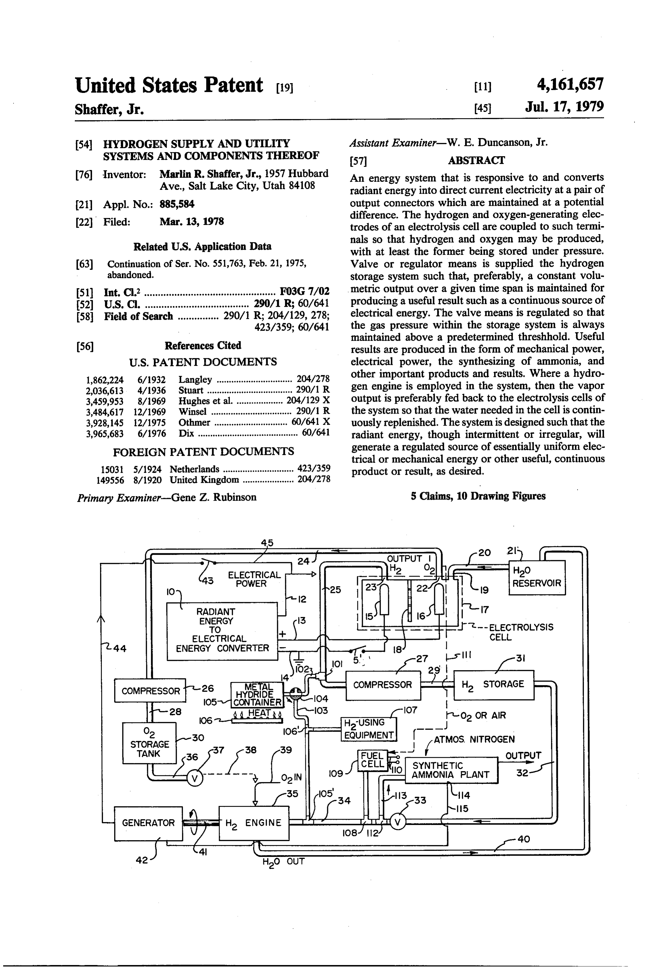
United States Patent (19) 11) 4,161,657 Shaffer, Jr. 45) Jul. 17, 1979 54 HYDROGEN SUPPLY AND UTILITY Assistant Examiner-W. E. Duncanson, Jr. SYSTEMS AND COMPONENTS THEREOF 57 ABSTRACT 76) Inventor: Marlin R. Shaffer, Jr., 1957 Hubbard An energy system that is responsive to and converts Ave., Salt Lake City, Utah 84108 radiant energy into direct current electricity at a pair of 21 Appl. No.: 885,584 output connectors which are maintained at a potential difference. The hydrogen and oxygen-generating elec 22 Filed: Mar. 13, 1978 trodes of an electrolysis cell are coupled to such termi Related U.S. Application Data nals so that hydrogen and oxygen may be produced, with at least the former being stored under pressure.
63 Continuation of Ser. No. 551,763, Feb. 21, 1975, Valve or regulator means is supplied the hydrogen abandoned. storage system such that, preferably, a constant volu (51) Int. C.’................................................ FO3G 7/02 metric output over a given time span is maintained for (52) so 290/1 R; 60/641 producing a useful result such as a continuous source of (58) Field of Search ............... 290/1 R; 204/129, 278; electrical energy. The valve means is regulated so that 423/359; 60/641 the gas pressure within the storage system is always
References Cited maintained above a predetermined threshhold. Useful (56) results are produced in the form of mechanical power,
1,862,224 6/1932 Langley ............................... 204/278 other important products and results. Where a hydro 2,036,613 4/1936 Stuart ................ ... 290/1 R gen engine is employed in the system, then the vapor 3,459,953 8/1969 Hughes et al. ... 204/129 X output is preferably fed back to the electrolysis cells of 3,484,617 12/1969 Winsel ................................. 290/1 R the system so that the water needed in the cell is contin 3,928, 145 12/1975 uously replenished. The system is designed such that the 3,965,683 6/1976 radiant energy, though intermittent or irregular, will FOREIGN PATENT DOCUMENTS generate a regulated source of essentially uniform elec trical or mechanical energy or other useful, continuous 15031 5/1924 Netherlands ............................. 423/359 product or result, as desired.
Primary Examiner-Gene Z. Rubinson 5 Claims, 10 Drawing Figures
RADIANT
ENERGY
ELECTRICAL
ENERGY CONVERTER
-O2 OR AIR
O2 HUSING ---
STORAGE
EQUIPMENT ? ATMOS NITROGEN
OUTPUT
GENERATOR is
Page 2
43 ELECTRICAL
RADANT
ENERGY
ELECTRICAL
ENERGY CONVERTER
NC COMPRESSOR CO H STORAGE
EQUIPMENT ? Atmos NITROGEN
OUTPUT
SYNTHETIC
AMMONA PLAN
Parvar- H2 ENGINE Etta Pit
RADIANT ENERGY MECHANICAL ENERGY
TO MECHANICAL TO ELECTRICAL
ENERGY CONVERTER ENERGY CONVERTER
HOT WATER
- - GENERATOR
FIG. 4
Page 3
Drawing sheet — no readable text.
Page 4
A further object of the invention is to provide an
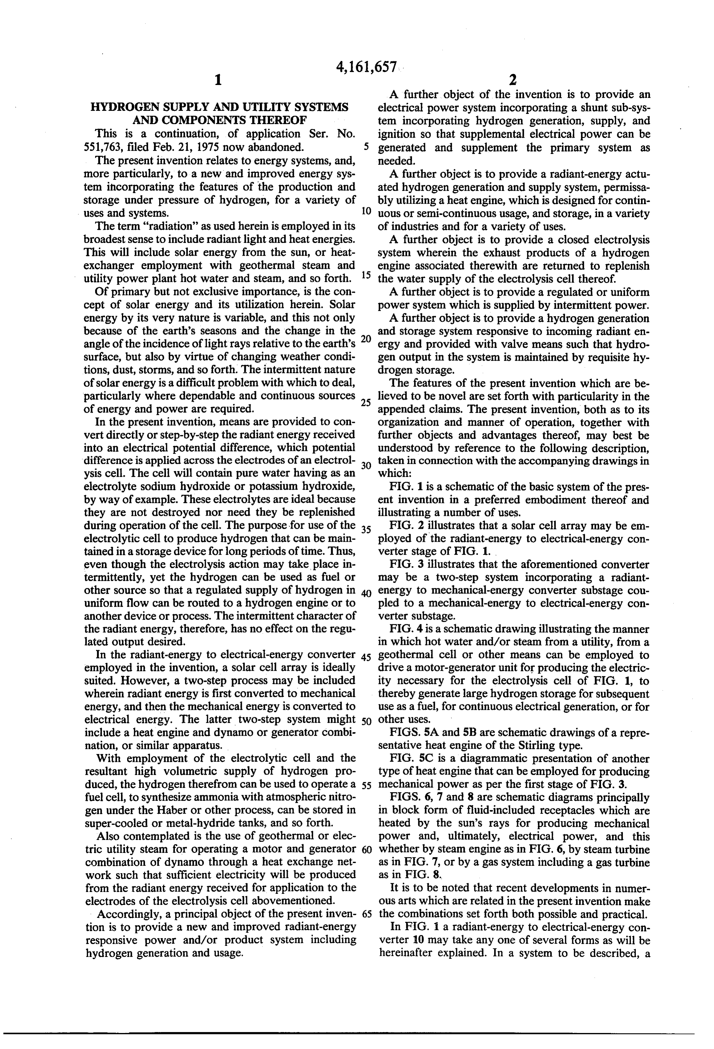
HYDROGEN SUPPLY AND UTILITY SYSTEMS electrical power system incorporating a shunt sub-sys AND COMPONENTS THEREOF tem incorporating hydrogen generation, supply, and This is a continuation, of application Ser. No. ignition so that supplemental electrical power can be 551,763, filed Feb. 21, 1975 now abandoned. 5 generated and supplement the primary system as The present invention relates to energy systems, and, needed.
more particularly, to a new and improved energy sys A further object is to provide a radiant-energy actu tem incorporating the features of the production and ated hydrogen generation and supply system, permissa storage under pressure of hydrogen, for a variety of bly utilizing a heat engine, which is designed for contin uses and systems. O uous or semi-continuous usage, and storage, in a variety The term "radiation' as used herein is employed in its of industries and for a variety of uses. broadest sense to include radiant light and heat energies. A further object is to provide a closed electrolysis This will include solar energy from the sun, or heat system wherein the exhaust products of a hydrogen exchanger employment with geothermal steam and engine associated therewith are returned to replenish utility power plant hot water and steam, and so forth. 15 the water supply of the electrolysis cell thereof. Of primary but not exclusive importance, is the con A further object is to provide a regulated or uniform cept of solar energy and its utilization herein. Solar power system which is supplied by intermittent power. energy by its very nature is variable, and this not only A further object is to provide a hydrogen generation because of the earth's seasons and the change in the 20 and storage system responsive to incoming radiant en angle of the incidence of light rays relative to the earth's ergy and provided with valve means such that hydro surface, but also by virtue of changing weather condi gen output in the system is maintained by requisite hy tions, dust, storms, and so forth. The intermittent nature drogen storage.
of solar energy is a difficult problem with which to deal, The features of the present invention which are be particularly where dependable and continuous sources 25 lieved to be novel are set forth with particularity in the of energy and power are required. appended claims. The present invention, both as to its In the present invention, means are provided to con organization and manner of operation, together with vert directly or step-by-step the radiant energy received further objects and advantages thereof, may best be into an electrical potential difference, which potential understood by reference to the following description, difference is applied across the electrodes of an electrol 30 taken in connection with the accompanying drawings in ysis cell. The cell will contain pure water having as an which:
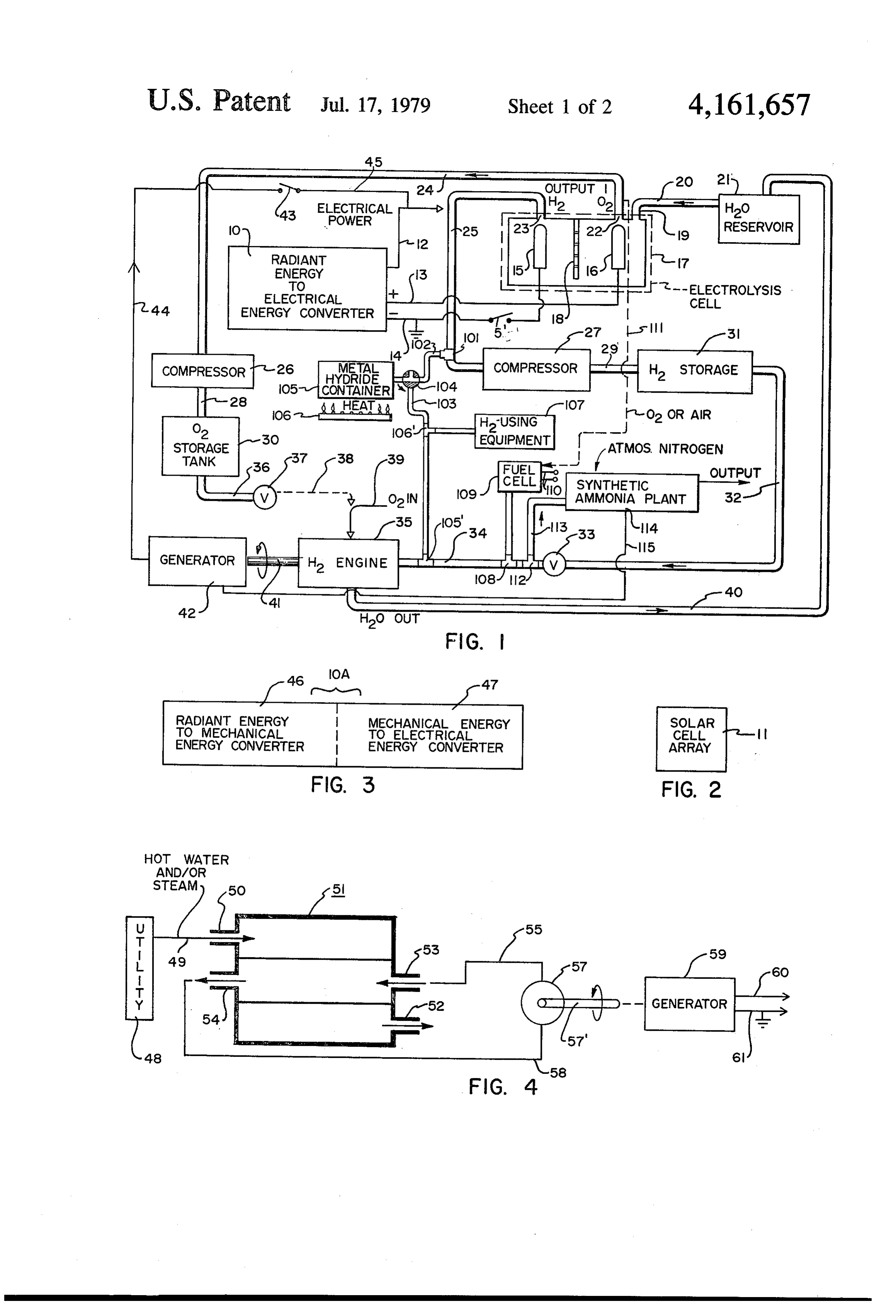
electrolyte sodium hydroxide or potassium hydroxide, FIG. 1 is a schematic of the basic system of the pres by way of example. These electrolytes are ideal because ent invention in a preferred embodiment thereof and they are not destroyed nor need they be replenished illustrating a number of uses.
during operation of the cell. The purpose for use of the 35 FIG. 2 illustrates that a solar cell array may be em electrolytic cell to produce hydrogen that can be main ployed of the radiant-energy to electrical-energy con tained in a storage device for long periods of time. Thus, verter stage of FIG. 1.
even though the electrolysis action may take place in FIG. 3 illustrates that the aforementioned converter termittently, yet the hydrogen can be used as fuel or may be a two-step system incorporating a radiant other source so that a regulated supply of hydrogen in 40 energy to mechanical-energy converter substage cou uniform flow can be routed to a hydrogen engine or to pled to a mechanical-energy to electrical-energy con another device or process. The intermittent character of verter substage.
the radiant energy, therefore, has no effect on the regu FIG. 4 is a schematic drawing illustrating the manner lated output desired. in which hot water and/or steam from a utility, from a In the radiant-energy to electrical-energy converter 45 geothermal cell or other means can be employed to employed in the invention, a solar cell array is ideally drive a motor-generator unit for producing the electric suited. However, a two-step process may be included ity necessary for the electrolysis cell of FIG. 1, to wherein radiant energy is first converted to mechanical thereby generate large hydrogen storage for subsequent energy, and then the mechanical energy is converted to use as a fuel, for continuous electrical generation, or for electrical energy. The latter two-step system might 50 other uses.
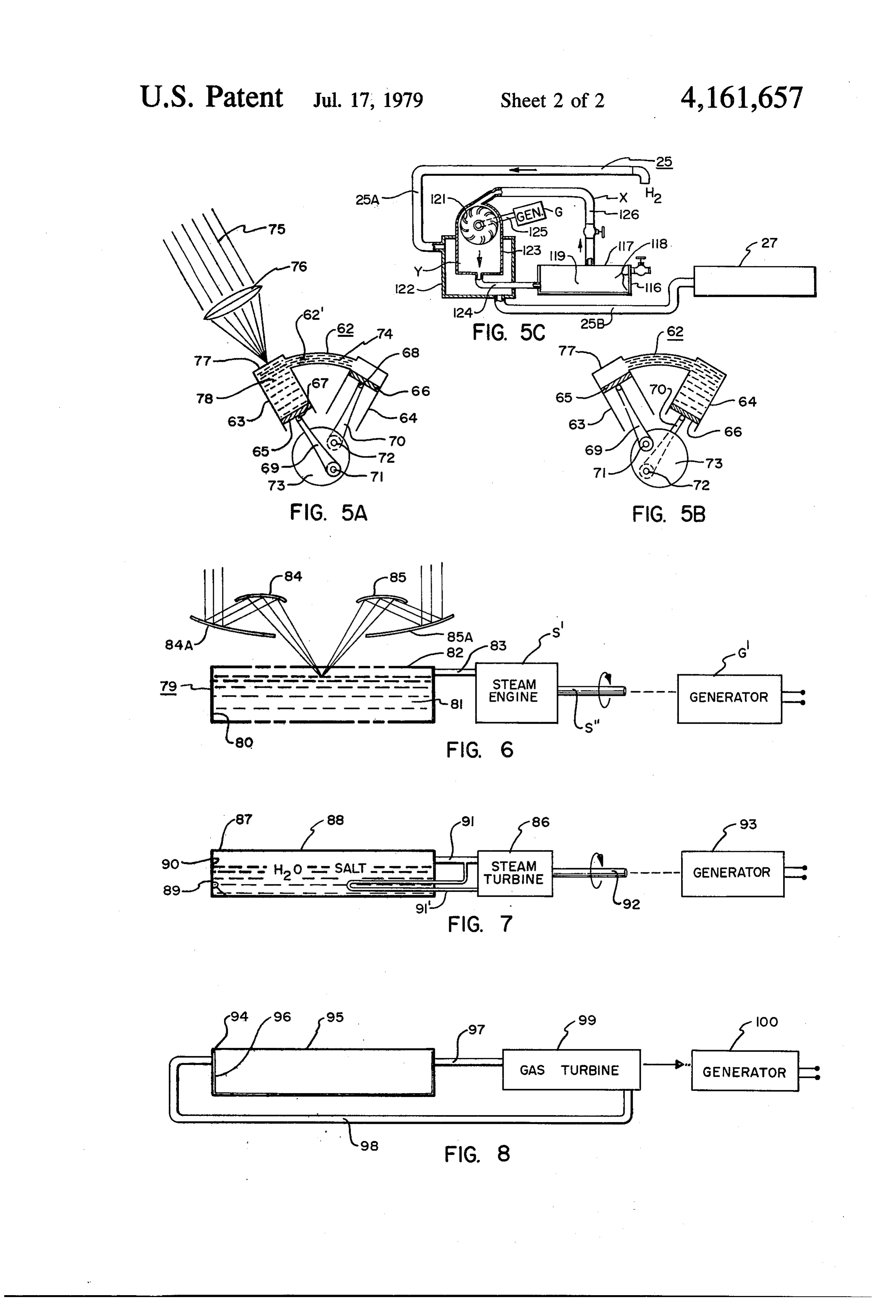
include a heat engine and dynamo or generator combi FIGS. 5A and 5B are schematic drawings of a repre nation, or similar apparatus. sentative heat engine of the Stirling type. With employment of the electrolytic cell and the FIG. 5C is a diagrammatic presentation of another resultant high volumetric supply of hydrogen pro type of heat engine that can be employed for producing duced, the hydrogen therefrom can be used to operate a 55 mechanical power as per the first stage of FIG. 3. fuel cell, to synthesize ammonia with atmospheric nitro FIGS. 6, 7 and 8 are schematic diagrams principally gen under the Haber or other process, can be stored in in block form of fluid-included receptacles which are super-cooled or metal-hydride tanks, and so forth. heated by the sun's rays for producing mechanical Also contemplated is the use of geothermal or elec power and, ultimately, electrical power, and this tric utility steam for operating a motor and generator whether by steam engine as in FIG. 6, by steam turbine combination of dynamo through a heat exchange net as in FIG. 7, or by a gas system including a gas turbine work such that sufficient electricity will be produced as in FIG. 8.
from the radiant energy received for application to the It is to be noted that recent developments in numer electrodes of the electrolysis cell abovementioned. ous arts which are related in the present invention make Accordingly, a principal object of the present inven 65 the combinations set forth both possible and practical. tion is to provide a new and improved radiant-energy In FIG. 1 a radiant-energy to electrical-energy con responsive power and/or product system including verter 10 may take any one of several forms as will be hydrogen generation and usage. hereinafter explained. In a system to be described, a
Page 5
highly unusual and efficient form of converter 10 will drogen generation at cell 17 be intermittent. This can be be a solar cell array 11 as seen in FIG, 2. accomplished, where device 31 is simply a pressure tank As to the solar cells, solar cell modules and arrays or cylinder, by using at 33 a self-regulated flow valve, that may be utilized in the present invention at 10 and such as a Racine flow valve, or by utilizing thereat a 11, the same are manufactured by many sources includ- 5 throttling-type regulator such as throttle regulators ing the silicon solar cell modules known as HFSP-2-40, manufactured by the Maxitrol Company of Detroit, manufactured by the Centrelab Semiconductor Divi Michigan. Alternatively, device 31 may comprise a pair sion of Globe Union Incorporated. Substantial reduc of series-coupled storage tanks, with a compressor in tion in the cost of silicon solar cells is at present very terposed therebetween and responsive to final tank promising in the developments made by Tyco Labora O internal pressure for maintaining a constant pressure tories, current efforts of which company are in the threshhold. Whatever structure is used, it is important production of silicon ribbon. This is an edge-defined, that hydrogen outflow proximate tee 112 be essentially film-fed growth (EFG) process which permits the constant, even if hydrogen generation at cell 17 might growth of crystals in a shape desired, i.e., ribbons which be intermittent due to ambient conditions. All compres can be readily converted into silicon wafers. Such de 15 sors herein can be supplied independent power sources, velopments promise to reduce the cost of silicon solar solar-powered or otherwise, or simply be coupled to cells by a factor of from 10-25. generator 42 or leads 12, 14, for example. Converter 10 will supply primary electrical power Oxygen storage tank 30 may be provided with outlet via lead 12 and also auxiliary electrical power at leads conduit 36 and valve 37 for simply producing an oxygen 13 and 14 which are coupled to electrodes 15 and 16 of 20 supply for any one of several purposes but which also electrolysis cell 17. Electrolysis cell 17 may take any may be coupled by conduit 38 as an oxygen intake, in one of several forms and in the usual configuration will lieu of air, to hydrogen engine 35. Of course, oxygen include a perforate baffle 18 disposed between the elec may likewise be supplied by the ambient atmosphere or trodes 15 and 16. by other means as is shown by oxygen inlet 39. The As to the electrolysis cells that can be utilized at 17 in 25 combustion product, namely, water, is drained from the FIG. 1, the most effective cells utilize an electrolyte of engine 35, is cooled, and is routed back to the reservoir approximately 34% by weight of potassium hydroxide 21 in a closed, water-replenishing system. Hydrogen or 25% by weight of sodium hydroxide, this when the engine 35 includes an output shaft 41 which is coupled cell is operated at about 170 F. This heat can be sup to electrical generator 42. Engine-generator, motor plied simply by the heat liberated during the electrolysis 30 generator, and dynamo are to be understood to be inter operation, so that such is sufficient to maintain the cell changeable and equivalent. The output of electrical at a desired operating temperature. Two types of cells generator 42 may be coupled back to the electrical are employed and both are usable in the invention power circuit at 12 via switch 43 and leads 44 and 45 herein. These types are called the unipolar or tank-type coupled thereto, as desired.
cell, and also the bipolar or filter-press type. Dia 35 Rather than employing a solar cell array for example, phragms used as at partition 18 in FIG. 1 prevent the as the converter 10, the converter may be itself formed mixing of hydrogen and oxygen and are generally of of two stages such as a radiant-energy to mechanical asbestos cloth, wire screen, or perforated nickel plate. energy convertersection 46 and a mechanical-energy to Typical examples of unipolar cells are the Knowles, electrical-energy converter section or stage 47, both Fausar and Burdett electrolytic cells. Closed tank uni- 40 forming a converter 10A corresponding to converter 10 polar cells include the International Oxygen Company in FIG. 1. See FIG. 3 in this regard. The mechanical and Consolidated Mining & Smelting Company tupe energy to electrical-energy converter would take the cells, by way of example. The cells above described form of the general direct current generator shown, for operate at 100% current efficiency, but on the basis of example, in FIGS. 4 and 6-8. The radiant-energy to energy consumption and work produced are about 45 mechanical-energy converter may take any one of sev 70-80% efficient. Note, however, that on the basis of eral forms as is illustrated in FIGS. 4-7. hydrogen and oxygen and per ampere hour delivered, In returning to FIG. 1, it is seen that a tee 101 may be these cells are practically 100% efficient. provided in conduit 25 to provide for the connection Cell 17 can be open rather than closed, and hence thereto of conduits 102 and 103 with three-way valve may comprise an ocean, a lake, pond, or watercourse, 50 104, used alternatively for charging container 105 and and especially those of brackish waters or simply con then for conducting hydrogen therefrom at desired taining salts. Further, the water supplied "cell' 17 may times. This combination is connected to a metal hy be reconstituted water absorbed from the atmosphere dride-containing container 105. By metal hydride is by a silica gel or dessicant, evaporated and distilled meant any metal which has the capacity to absorb hy therefrom. 55 drogen gas. A number of metals, metal alloys and mix Electrolysis cell 17 will include a water inlet port 19 tures are available. Palladium metal is one possible sub to which inlet conduit 20, leading from water reservoir stance that will hold 800 volumes of hydrogen at room 21, is connected. Electrolysis cell ports 22 and 23 are temperature and atmospheric pressure. The weight respectively coupled by conduits 24 and 25 to compres absorbed will increase with the pressure at which the sors 26 and 27. Compressors 26 and 27 are each respec system is operated. Metallic uranium will also absorb tively coupled by conduits 28 and 29 to oxygen storage considerable quantities of hydrogen at room tempera device 30 and hydrogen storage device 31, respectively. ture and release it when elevated in temperature. Where Turning first to the hydrogen storage device 31, it is a heat source is needed, the same may be supplied proxi seen that conduit 32 leads therefrom through manually mate the container 105 as at heat source 106 in FIG.1. or otherwise actuatable valve 33, coupling therefrom to 65 Line 103 is connected to conduit 34 via tee 105", sup conduit 34 that serves as a hydrogen intake for hydro plied as needed. Line 103 may likewise be provided gen engine 35. It is important that device 31 supply a with a tee connection at 106 where the hydrogen re constant volume of gas per unit time even though hy ceived from the metal hydride within container 105 is
Page 6
delivered to a hydrogen utilizing equipment or unit at The hydrogen produced in FIG. 1 is stored at 31 and 107. then fuels at desired times engine 35 for supplying addi FIG. 1 also illustrates that a tee connection 108 lead tional electrical energy at 44. Such a facility, excess ing to H-O fuel cell 109 may be provided for generating electricity or power during off peak-load periods can be electricity at 110. Fuel cells of current design and oper employed to generate hydrogen and, subsequently, ating on hydrogen as delivered by tee 108 may be from additional electrical power to satisfy peak load added 40-70% efficient. The oxygen needed by the fuel cell requirements, thereby reducing utility size and costs. can be supplied directly from line 24, as indicated by FIGS. 5A and 5B illustrate an optional type of radi branch line 111 or may be simply supplied by the air, ant-energy to mechanical-energy converter in FIG.3 as A tee 112 may likewise be used with a conduit 113 10 by what is known as a Stirling hot-air engine. See Stir coupling to a synthetic ammonia plant 114. These plants ling engine 62 in FIGS. 5A and 5B. The conventional here will operate by use of distilled atmospheric nitro Stirling engine is shown in diagrammatic form and in gen for example and compressed hydrogen as delivered cludes cylinders 63 and 64 with pistons 65 and 66. Cou by valve 33 and hydrogenstorage device 31 but without pled to each piston by a pivot pin 67 and 68 is a swing the usual steam and fossil fuel or petroleum feedstocks 15 ing piston rod 69 and 70, respectively. Each of these otherwise necessary to produce the hydrogen required. piston rods are pinned at 71 and 72 to conventional There are many types of synthetic ammonia plants in flywheel 73. Cylinders 63 and 64 are intercoupled by existence utilizable at 114 and using many types of pro conduit 74 of relatively small size which includes a cesses, known as, for example, the Haber process, the heat-trapping steel-wool type gauze at 62. The gauze is Haber-Bosch process, the Fauser process, the so-called 20 air pervious and yet tends to keep the heat entrapped NEC process, and so forth; plants utilizing one or more within cylinder 63. Hot-air engines of the type shown in of these processes have been built by many companies FIGS.5A and 5B are quite efficient, noiseless and show including the Kellog Company, Nitrogen Engineering considerable promise. The principle of operation is that Corporation, also known as the Nitrogen Research the sun's rays at 75 are focused by a reflector or focus Laboratory of the United States. Thus, both hydrogen 25 through a lens 76 to a translucent or transparent platic and electric power may be supplied the ammonia plant window 77 to heat the air or other fluid 78 within cylin 114 via electrical power lead 115 and the hydrogen der 63 above piston 65. The rapidly expanding air urges proceeding by conduit 113 to the plant. piston 65 downwardly and, by virtue of the flywheel 73, It is most important to note that ammonia, which is an piston 66 upwardly. As the flywheel continues to turn it important constituent of nitrogen fertilizer, is herein 30 moves the second piston 66 downwardly and piston 65 very inexpensively produced, this simply through the upwardly, thereby forcing the hot air in a direction to use of water, air, and radiant energy such as heat or the the right through conduit 74 into cylinder 64 above sun's rays, for producing by electrolysis both power and piston 66. At this point the heat is exhausted in cylinder hydrogen to operate the plant. 64 and the sun's rays at 75 will operate to reheat again By virtue of the solar-powered systems, for example, 35 the volumetric air in cylinder 63 above piston 65. Steel of the subject invention, hydrogen is generated ex wool gauze 62 is used to preheat the now-cooled air in tremely inexpensively. Herefore, use of hydrogen as a cylinder 64 which returns to cylinder 63. The pre fuel has been extremely limited to certain special indus heated air is expanded further as aforesaid by the light trial purposes, this because of the great cost of produc from the sun that heats the air above piston 65. It is ing hydrogen. In the past, the methods of producing 40 noted that this is a thermal heat engine machine of a commercially hydrogen favor the catalytic oxidation of closed-system type.
carbon monoxide in blue-water gas. Low temperature In FIG. 5C a closed container 116 is employed which fractionation of coal gas has also been used. These are includes a transparent or translucent top 117 and also an expensive processes and require the presence of valu inner side and bottom "black' layer 118. The tank 116 is able hydrocarbons and fossil fuels. The present inven 45 filled, through the side valve shown, with one of the tion, in contrast, simply provides a usable fuel, namely so-called true gasses or simply with an easily vaporized hydrogen or ammonia, by the presence merely of water, liquid such as ammonia dissolved in water. air, and solar power, for example. The upper surface 117 is exposed to sunlight, heat, or In FIG. 4, hot water and/or steam from a geothermal other radiant energy source so as to vaporize or expand plant or from an electrical generating facility such as a 50 the working fluid 119 within the interior of container nuclear power plant or hydrocarbon fuel type power 116. The vapor or gas rises in conduit combination 126 plant as at 48 provides a hot water or steam residual to proceed to turbine 121. Jacket means 122 is disposed output which is coupled by conduit 49 to input port 50 about hollow cylindrical structure 123 beneath the tur of heat exchanger 51. The super-heated water or steam bine, the latter being connected by conduit 124 back to passes through the heat exchanger and out exhaust port 55 container 116. The means 122, of increased volume, is 52. Ports 53 and 54 are coupled by conduits 55 and 56 as used to cool the structure 123 and the working fluid indicated to a heat engine 57. The latter may comprise used passing therethrough in the direction shown by the a steam engine, a vapor or gas engine, an ammonium arrow by virtue of gas expansion in 122. Hence, this engine, and so forth, at 57. In any event, there will be, cooling may be ideally performed by the insertion of for engine 57, a mechanical output shaft at 57" that can condenser or cooling unit 122 into hydrogen line 25, see run generator 59 to produce electrical energy at 60 and FIG. 1, and shown here as line portions 25A and 25B. 61. Accordingly, in FIG. 4 the energy from the hot The portion 25B will again be connected directly to water or steam of the electrical generating facility such compressor 27, hydrogen thus serving as said working as a public utility electrical power plant, for example, is fluid.
utilized as to its super-heated water or steam to run a 65 In operation in FIG. 5C, the true gas is heated and small stand-by, auxiliary, or shunt facility that can pro expands or vapor such as ammonia from an ammonia duce an additional electrical current suitable for cou water solution is vaporized upwardly such that the pling to the electrolysis cell 17 of FIG. 1. gaseous or vapor stream enters and moves turbine 121.
Page 7
This vapor is cooled at structure 123 since there exits a pled by conduits 97 and 98 to gas turbine 99 of a low heat exchange communication with the interior of pressure, low-temperature type. Accordingly, the sun's structure 122. It is noted that structure 122 is an en rays radiate downwardly upon translucent or transpar larged cavity leading to compressor 27. Accordingly, ent face 95 to heat the fluid disposed within the tank, the hydrogen generated at the electrolysis cell 17 is 5 and such gas is used to revolve the turbine 99 which, in utilized and expanded proximate structure 123 so as to turn, is coupled to and drives generator 100. cool this area and thereby supply a pressure gradient or The terms "power' and "energy' as used herein shall differential as between the vapor pressure at X and the be considered synonymous which shall include both pressure at Y. This provides a turning of the turbine 121 electricity and heat, by way of example. Thus, unit 35 in so that the turbine may be used to supply mechanical, or 10 FIG. 1 may comprise simply a furnace using oxidized electrical power at generator G in FIG. 5C via the hydrogen fuel which can be employed to serve as a revolving coupler shaft 125 which generator G may supplementary heat source for heating or cooling solar indeed comprise the mechanical-energy to electrical heated homes and other buildings. The invention is energy converter 47 in FIG. 3. The shaft 125 may be usable in every context wherein hydrogen, or electric adapted for manual revolvement until the system gets 15 ity, or heat produced therefrom, are to be employed as up to a speed sufficient to release the necessary, hydro gen to cool the lower structure 123 and thereby supply astandby continuous "power' source which will serve as a the gaseous pressure gradient upon which revolving SOUCS or auxiliary unit to supplement primary turbine 121 will rely. While particular embodiments of the present inven FIG. 5C illustrates therefore, another form of prim tion have been shown and described, it will be obvious mover for supplying energy such that the same may be to those skilled in the art that changes and modifications coupled to electrodes 15 and 16 by virtue of leads 14 may be made without departing from this invention in and 15 and the switch S' used.
Other means of producing mechanical power to sup its broader aspects, and, therefore, the aim in the ap pended claims is to cover all such changes and modifi ply electrical energy for electrodes 15, 16 of the cell 17 25 cations as fall within the true spirit and scope of this in FIG. 1 from radiation is shown in FIG. 6. Thus, a invention.
very large shallow vessel at 79 is supplied a black coat claim:
ing at 80 and is filled with water or other liquid or fluid 1. An electrical power system including, in combina at 81. A series of reflectors 84A, 85A, 84, and 85, are used to concentrate the sun's rays in a particular area. 30 tion: first structural means directly responsive to in pingement thereon of the sun's rays for converting the
For convenience of illustration, the vessel has been expanded in a horizontal direction relative to the reflec sun's radiant energy in said rays as so received into tors. Thus, the shallow pool may be many times smaller electrical energy, said first means including a pair of in dimension than the distance between the reflectors opposite-polarity, electolysis, electrical connectors; 84A and 85A. In any event, the sun's rays are concen 35 second electrolysis means having water incorporating a trated on the darkened or black surface 80 to produce a salt-type electrolyte for generating hydrogen at a lower low pressure steam within the vessel and beneath the pressure and also oxygen, said second means having a transparent or translucent top 82 thereof. The steam is pair of separated electrodes respectively coupled to said conducted by conduit 83 to a steam engine S which electrical connectors, a water inlet, and hydrogen and produces mechanical output power at shaft S". Shaft S' oxygen gas outlet ports respectively disposed cooper may be coupled to electrical generator G' such that the ably with said electrodes; third means coupled to said latter may generate a DC current. hydrogen port and utilizing the hydrogen therefrom for The structure in FIG. 7 is slightly different, this time producing a useful result; hydrogen storage means, including a steam turbine 86. Vessel 87 has a translucent including an electrically operated compressor, inter top as of glass or plastic at 88 and includes on the sides 45 posed between said second and third means, for storing and bottom thereof at 89 dark black coating 90. Dis hydrogen at a higher pressure, said hydrogen storage posed within the vessel in FIG. 7 is a water which is means being provided with means for regulating hydro preferably brine laden such that the temperature of the gen flow from said hydrogen storage means to said water will rise appreciably and will remain hot for a third means for essentially uniform flow. substantial period of time. The steam generated, of from 50 2. The combination of claim 1 wherein said first struc one to two atmospheres, is piped through conduit 91 tural means comprises a solar cell array. into a conventional low-pressure operated steam tur 3. The combination of claim 1 wherein said first struc bine 86 for producing mechanical power at shaft 92 of tural means comprises solar-heating-vessel for generat the turbine. This shaft again powers DC generator 93. ing steam and a turbine-generator coupled thereto. Alternatively, a hairpin configured conduit 91" can be 55 4. The combination of claim 1 wherein said first struc immersed in the brine to supply circulating vapor pres tural means comprises a solar heat engine, and electrici sure to turbine 86. . " ty-generating means coupled thereto. In FIG. 8 there is likewise a vessel at 94 having a 5. The combination of claim 1 wherein said third translucent or transparent top surface made of glass or means has a water exhaust and includes water-flow plastic as at 95. A darkened, painted or pitch surface 96 conduit means coupled to said second electrolysis is provided. The vessel in FIG.8 may be filled with any means whereby to route said water-exhaust from said type of fluid, gas or liquid which is heated to a gaseous third means back to said second electrolysis means to state by the sun's rays to revolve gas turbine. Thus, the replenish the water supply
thereof.
vessel at 94 includes the fluid and the vessel was cou
Provenance
- Collection
- Cited prior art
- Original PDF
- patentimages.storage.googleapis.com →
- Filed
- 1978-03-13
- Pages
- 7
- Method
- pdftotext (the PDF's own text layer) + pdftoppm 300dpi page scans
- Source
- Google Patents bibliographic record
- Granted
- 1979-07-17
- Inventors
- Marlin R. Shaffer, Jr.
- Transcribed from
- patentimages.storage.googleapis.com →