patent · US3863621
Solar wall system
4 February 1975
Page 1 — bibliographic record
United States Patent (19) [11] 3,863,621 Schoenfelder (45) Feb. 4, 1975
54). SOLAR WALL SYSTEM
75 Inventor: James L. Schoenfelder, Iowa City, Primary Examiner-William F. O'Dea Iowa Assistant Examiner-Peter D. Ferguson
Attorney, Agent, or Firm-Zarley, McKee, Thomte & 73) Assignee: Iowa State University Research Voorhees
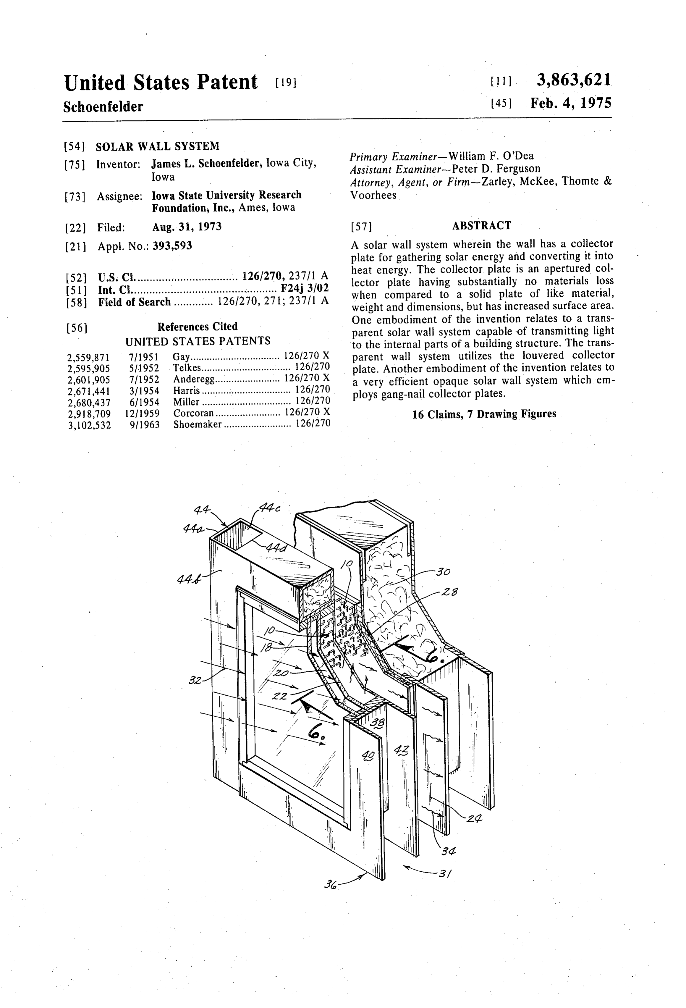
Foundation, Inc., Ames, Iowa 22 Filed: Aug. 31, 1973 57 ABSTRACT (21) Appl. No.: 393,593 A solar wall system wherein the wall has a collector plate for gathering solar energy and converting it into heat energy. The collector plate is an apertured col 52 U.S. C. .................................. 126/270, 237/1 A lector plate having substantially no materials loss I51) Int. Ch................................................ F24j.3/02 when compared to a solid plate of like material, 58 Field of Search ............. 1261270, 271; 237/1 A weight and dimensions, but has increased surface area. One embodiment of the invention relates to a trans 56) References Cited parent solar wall system capable of transmitting light UNITED STATES PATENTS to the internal parts of a building structure. The trans 2,559,871 7|1951 Gay................................. 126/270 X parent wall system utilizes the louvered collector 2,595,905 5/1952 Telkes................................. 1261270 plate. Another embodiment of the invention relates to 2,601,905 7|1952 Anderegg................ ... 126/270 X a very efficient opaque solar wall system which em 2,671,441 3/1954 Harris................................. 126/270 ploys gang-nail collector plates. 2,680,437 6/1954 Miller................................. 1261270 2,918,709 12/1959 Corcoran............ 126/270 X 16 Claims, 7 Drawing Figures 3,102,532 9/1963 Shoemaker......................... 1261270
Page 2
Drawing sheet — no readable text.
Page 3
SOLAR WALL SYSTEM The method of accomplishing these and other objects
BACKGROUND OF THE INVENTION
will become apparent from the following description of the invention.
Solar heat collecting wall systems represent one pos SUMMARY OF THE INVENTION sible method of relieving a part of our current energy 5 crisis. Approximately one-third of all energy consumed This invention relates to solar wall systems employing in this country during the year 1971 was for space heat a unique and specially designed apertured collector ing and air conditioning. This is a tremendous drain on plate. The utilization of the collector described herein our country's fuel reserves. Efficient and consumer ac after allows for increased efficiency in conversion of ceptable solar wall systems which would utilization of O solar energy into heat energy. In one embodiment the solar energy as an alternative to fossil fuels for heating invention relates to a transparent, or see-through, wall and lighting would be a great aid in relieving this cur system which allows light to pass into the interior of a rent crisis. building structure and which allows those within the Solar wall systems have been developed heretofore. building to see out.
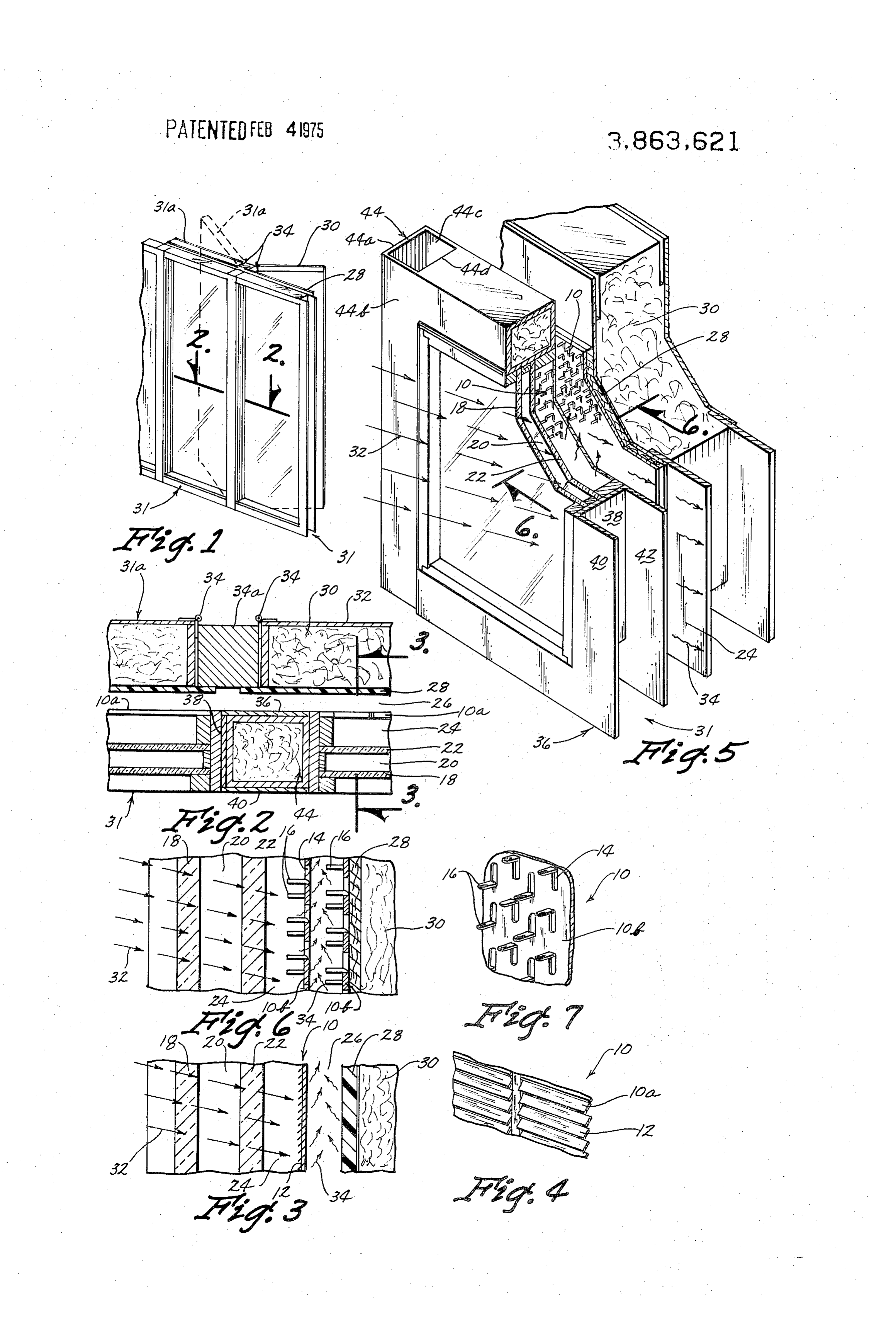
However, no solar wall system yet developed has gener 15 In another embodiment the invention relates to an ally been accepted by the public as a convenient heat extremely efficient opaque solar wall system. In yet an source for homes and other building structures. Part of wall other embodiment of the invention relates to a solar the problem with prior art solar wall systems is that put together system, comprised of modular units, which can be most, if not all of them, have been opaque. Thus while 20 with a minimum at a construction jobsite efficiently and the wall system will allow for capturing solar energy of required skill. and converting it into heat energy, it is at the sacrifice DESCRIPTION OF THE DRAWINGS of allowing light to enter to the interior of the building FIG. 1 is a perspective view of a transparent solar structure. Prior art solar wall systems have been wall opaque because it was thought that in order to effi 25 units.system employing exterior and interior modular ciently collect solar energy an opaque wall system was FIG. 2 is a sectional view along line 2-2 of FIG. 1. deemed essential. In other words, a solar wall system which would allow light into the interior of a building showing3 aiscross
FIG. a sectional view of FIG. 2 along line 3-3 section of a transparent wall construc structure would not be as efficient since it would allow tion where a louvered collector plate is employed. escape of heat energy. Of course, since building struc 30 FIG. 4 is a fragmentary view of a louvered collector tures having large opaque areas in the walls thereof, are plate.
not favored by the public this factor has considerably FIG. 5 is an expanded perspective view of exterior decreased the acceptability of solar heat as a means of and interior modules for a solar wall system employing heating homes and other buildings. Accordingly, there gang-nail collector plates.
is a real need in the art for the development of a solar 35 FIG. 6 is a sectional view of FIG. 5 along lines 6-6 wall system which will efficiently collect solar energy, showing in cross section wall construction where gang convert that energy into heat energy and at the same nail collectors are employed.
time, allow for transmission of light into the interior of FIG. 7 is a fragmentary review of a gang-nail collec the building structure. tor plate.
An additional deficiency of prior art solar wall sys 40 tems relates to their general inability to efficiently col DETAILED DESCRIPTION OF THE INVENTION. lect solar energy and convert that energy into heat A collector plate, as utilized herein, refers to a metal without a substantial loss of the heat. It has now been sheet which is utilized to collect the solar energy. Typi discovered that solar wall systems, utilizing special col 45 cally collector plates are painted a dark highly absorb lector plates for the solar energy, will allow for in tive color such as flat black color. Solar rays hit the creased efficiency in gathering solar energy and con plate and are converted thereon into heat energy as the verting that energy into heat energy. In other words, plate is warmed by the solar energy. Such collector the amount of heat energy which is allowed to dissipate plates can be made of any suitable material of high without being utilized is decreased. solar absorbtivity and are typically made from copper, Another deficiency with many prior art solar wall sys 50 aluminim, steel and galvanized iron. Many types of col tems relates to their generally complicated structure lector plates have been employed in the prior art. For and the long times necessary for jobsite construction. example, the prior art has utilized flat sheet-like collec The solar wall system of this invention can, if desired, tor plates, corrugated collector plates, collector plates be built in modules or units which can quickly and effi 55 faced with copper water pipes and metallic fibrous ma ciently be constructed at the construction jobsite. terials. For examples of typical prior art collector plates Accordingly, one object of this invention is to de see the following U.S. patents: Harris, U.S. Pat. No. velop a solar wall system which will efficiently collect 2,671,441; Anderegg, U.S. Pat. No. 2,601,905; Gay, heat energy and still allow for passage of light into the U.S. Pat. No. 2,559,870; Johnston, U.S. Pat. No. interior of a building structure. 60 2,998,005; Thomason, U.S. Pat. No. 3,295,591; and Yet another object of this invention is to provide a Hay, U.S. Pat. No. 3,563,305. The efficiency of any solar wall system having a special type of solar energy solar wall system depends directly upon the efficiency collection plate which more efficiently will convert of the collector plate in gathering solar energy and con solar energy into heat energy. verting it into heat energy.
Still another object of this invention is to provide a 65 It has now been discovered that increased solar en solar wall system in modular units which can be quickly ergy conversion into heat energy can be otained when constructed at the construction jobsite with a minimum specially designed collector plates are utilized. These of required skill and with great efficiency, plates can generally be described as apertured collector
Page 4
plates. An apertured collector plate, as that term is louvered collector plate. FIG. 6 is a similar cross sec used herein, does not mean a collector plate which tional view of a solar wall construction employing gang merely has holes punched therein. A collector plate nail collector plates.
having holes punched therein will naturally have a ma While the collector plates shown in the drawings gen terials loss when compared to a solid plate of like mate 5 erally relate to a preferred modular unit solar wall sys rial, weight and dimensions. Thus, the surface area of can tem, it should be appreciated that the solar wall system the overall collector plate will be decreased. In accord equally as well, if desired, be built as an entire wall with this invention it has been discovered that aper section.
generally
Where this is done the views of FIGS. 3 and 6 will represent, a sectional view of the various tured collector plates which have substantially no ma terials loss when compared to a solid plate of like mate O layers, in laminar relationship, comprising the wall rial, weight and dimension, provide increased surface structure. Conventional wall frame means can be uti area, and in addition, will transmit light therethrough. lized to hold the various solar wall system layers into The increased surface area results in a greater in their hereinafter described relationship and thus this creased efficiency for collection of solar energy and 15 conventional in detail.
frame structure will not be described here conversion of that energy into heat energy. Thus, while the collector plate does have apertures therein, the ma In both FIGS. 3 and 6, the left hand side thereof, rep terial displaced in forming the apertures is not com resents the exteriorly exposed portion of the wall, with pletely removed from the collector plate. Examples of the right hand side thereof representing the interiorly such collector plates, formed without a materials loss, disposed portion of the wall. Speaking now with spe are shown in FIGS. 4 and 7. FIG. 4 shows a louvered 20 cific reference to FIG. 3, there is shown a transparent collector plate wherein the metal is punched or other or see-through solar wall system. This system comprises wise pressed in a dye to provide louvers therein. Thus an exteriorly exposed transparent member 18, a void there are apertures present but the material displaced space 20, and spaced apart from but behind the exteri in forming the apertures is not removed from the col 25 orly exposed transparent member 18 is an interiorly lector plate. Obviously then, the overall surface area disposed transparent member 22. Of course, there can for collection of solar energy is increased. The collec be more than two transparent members and if desired, tor plate is referred to herein as 10 and the louvered the number can be from two up to four. However, for collector plate is referred to as 10a with the gang-nail purposes of cost efficiency two transparent members collector plate, to be described in detail hereinafter, re 30 are preferred. The transparent members can be con ferred to as 10b. ventional plate glass, or made of transparent plexiglass The louvered collector plate, 10a formed by having material. Thermopane glass can also be employed. Be generally downwardly and outwardly displaced louvers hind the most interiorly disposed transparent member 12 formed in a metal sheet. These louvers will provide 22, is an additional air space 24 and spaced apart from increased surface areas for gathering solar energy and 35 transparent member 22 and behind said member is a converting it into heat energy and, as explained in more louvered collector plate 10a. Immediately behind lou detail hereinafter, will allow light to be transmitted vered collector plate 10a is an air space chamber 26 for therethrough. As a result, one looking through a solar collection and movement of warm air. The rear wall of wall system employing louvered collector plates can space panel chamber 26 can be defined by any conventional material 28 which in FIG. 3 is transparent. Be see out to the exterior of this structure.
Collector plate 10b is a gang-nail collector plate. 40 hind panel 28 and in abutting relationship therewith is Gang-nail collector plate, 10b, has apertures 14 and up an insulation layer 30. Insulation layer 30 can comprise standing tabs 16. Of course, other collector plates hav any well known insulating material. For example, it can ing apertured surfaces wherein the apertured collector be foam plastic insulation such as urethane foam; it can plate has no materials loss when compared with a plate 45 be a fiber insulation such as fiberglass butt; or it can be of like size, weight and dimensions can easily be made. alike. loose fill insulation such as fiberglass pellets and the Insulation layer 30 is the most interiorly disposed
Thus, the louvered collector plate 10a, and the gang nail collector 10b, are shown herein as representative portion of the solar wall system. Of course, behind insu only. The key feature being that these plates have no lation layer 30 can be any wall panel construction suit materials loss when compared with like plates of similar 50 able for exposure within the internal wall of the build size, weight and dimension but on the other hand, do ing. This could conceivably be wood paneling, any con have an increased surface area. A description of the ac ventional dry wall construction, or the like. As will be tion of these plates in collecting solar rays will be pro explained hereinafter, with regard to the embodiment vided hereinafter. shown specifically in FIG. 3, the insulation layer is movably connected to the remainder of the solar wall
FIGS. 1, 2, 3 and 4 represent a solar wall system hav 55 system ing a louvered collector plate and are designed to pro therefrom so that the insulation layer can be moved away vide a transparent, or more accurately perhaps a see to allow light to pass through the solar wall and to allow through solar wall system wherein light is transmitted outside. In this those within the building structure to see to the interior of the structure and one standing there specific embodiment, therefore, panel within can see out to the exterior thereof. FIGS. 5, 6, 60 28 is preferably another see-through panel of glass or and 7 represent an opaque solar wall system having en plexiglass material.
hanced efficiency for collection of solar energy, con scribed During in use operation the solar wall system de version of that energy into heat energy and distribution in FIG. 3 operates as follows. Sun rays repre thereof within the building structure. For purposes of sented by arrows 32 pass through transparent members 18 and 20 and hit the louvers 12 of louvered collector general description of the invention and for clarity, the 65 plate 10a. The collector plate is warmed by the sun rays invention will first be described in connection with the cross sectional views of FIGS. 3 and 6. FIG. 3 is a sec 32 and the collector plate 10a, which is typically tional view of a solar wall construction employing a painted flat black, converts the sun rays 32 into heat
Page 5
energy. Because of the increased surface area of collec See-through condition. For exemplary purposes, this tor plate 10a over a simple metal sheet collector plate can be seen in FIG. 2, interior modular unit 31a is or over a corrugated collector plate, the absorption and shown as being hingedly connected by hinge 34 to a coversion of solar energy into heat energy is increased. post member 34a so that it can be swung rearwardly. The heat energy warms the air in air space chamber 26 Exterior modular unit 31 comprises the exposed ex and the warm air 34 can be swept away for heating the teriorly disposed transparent member 18, any interiorly building structure. Heat loss of the collected heat en disposed transparent members 22, and the collector ergy is significantly decreased by the presence of panel plate 10b. The frame of exterior modular unit 31 is 28 and insulation layer 30. Heat loss by conduction to uniquely designed to provide for easy jobsite construc the exterior of the wall construction system is pre O tion of solar walls. The frame can be aluminum, or any vented by design of collector plate 10a, and the spaced other suitable metal or wood. The modular unit is pref. apart relationship of the transparent members 18 and erably rectangular in shape and has two adjacent sides 22. The means for sweeping away warm air and circu forming open frame members of U-shaped cross sec lating it through the building structure are conventional 5 tion. This is best seen in FIG. 5 wherein the open frame but will briefly be described hereinafter. members generally designated in FIG. 5 as 36 are com The wall construction shown in FIG. 6 is similar to prised of an outwardly extending sidewall 40 a back that shown in FIG. 3 but is specifically designed for standing sidewall 38 and an additional outward extend highly efficient opaque solar wall system. Those por ing sidewall 42. The other sides of the modular unit 31 tions of the structure of like construction to those pre comprise closed frame member 44 formed by walls viously described will not be described here in detail. 44b, 44a, 44c and a wall 44d, not depicted in FIG.S. Like numerals have been utilized to represent like The dimensions of closed frame member 44 are such structure. In FIG. 6 there is shown a first gang-nail col that it will matingly receive the open frame member 36. lector plate 10b and spaced apart therefrom but behind Thus as can be seen in FIG. 2, open frame member 36 first gang-nail collector plate 10b is a second gang-nail 25 will matingly receive closed frame member 44 to pro collector plate also represented by numeral 10b. There vide a solid fit. In this fashion modular units can be chamber 26, then, is defined by the back of first gang built one matingly receiving the other until a solar wall nail collector plate 10b and the front of second gang system of desired size is achieved. Preferably, the open nail collector plate 10b. Behind second gang-nail col space in closed frame member 44 is filled with insula lector plate 10b is a panel 28 which can be wood or tion. This will allow for an even increased efficiency in other opaque conventional materials since this wall sys 30 thermal retention. As can be seen from FIG. 5, the inte tem is an opaque one. Spaced directly behind panel 28 rior modular unit 31a can also be comprised of like and in abutting relationship thereto is insulation layer configuration having open frame members and closed 30. In the construction of FIG. 6, those rays which pass frame members which will matingly receive one an through the apertures of the first gang-nail collector other. In such a manner a solar wall system can be built plate 10b will strike the second collector plate 10b 35 by unskilled labor and does not require a detailed fa which is preferably in offset relationship with regard to miliarity with the intricate construction of the entire the first collector plate 10b. As a result an enhanced ef wall system. In addition each modular is in and of itself ficiency of solar energy collection is achieved. More surrounded by an insulation layer which makes heat over, the combined increased exposed surface areas of 40 loss significantly less.
gang-nail collector plates 10b make them extremely ef. As heretofore mentioned, the method of storing and ficient in solar energy collection. circulating warmed air 34 which is warmed in air cham FIGS. 1 and 2 show with particularity the solar wall ber 26 is conventional. For example, a fan system and system construction wherein the wall is comprised of warm air storage unit can be located remotely in build modular units with an exterior modular unit generally 45 ing structure with the fan system being in communica designated at 31 and a movably mounted interior mod tion with warm air 34 in air chamber 26. The warmed ular unit generally designated at 31a. This system is de air is swept into a storage system wherein it is forced signed for utilization wherein the solar wall system is to throughout the interior of the building by conventional be a see-through solar wall. the interior modular unit warm air conveying and conduction means. Cold air comprises the insulation layer 30 and any appropriate 50 from the home can be recirculated back into the fan covering thereover. Positioned in front of the interior system wherein it is warmed by incoming hot air and modular unit 31a is a stationary transparent member. then recirculated throughout the home. This cyclical The movably mounted interior modular unit when in process can continue in a generally continuous fashion. closed position is in abutting relationship with the inte Heat storage, can be accomplished in conventional riorly disposed transparent member 28. Thus when the 55 means by utilization of conventional heat sinks such as interiorly disposed modular unit is moved away from water which is warmed, sodium sulphate salt which is abutting relationship with interiorly disposed transpar warmed, and the like.
ent member 28 light can pass through transparent As can be seen, the various combinations of structure members 18 and 22, through louvered collector plate of this invention provide an extremely efficient solar 10a, and through transparent member 28 and into the 60 heat collection means and wall system therefor. The internal structure of the building. It is desirable to keep system also provides a solar wall system which will the movably mounted interior modular unit in a closed allow light to pass therethrough and yet extremely effi position during early morning hours so that collector ciently collect solar energy. Additionally, the solar wall plate 10a can satisfactorily reach a warm temperature. system provides for convenient modules which can be Thereafter once sufficient heat exchange is occuring, 65 easily made, transported and constructed on the job interior insulation layer 30 and the modular unit which site. Thus the invention accomplishes all of the hereto incorporates it can be moved away from the exterior foreWhat stated objectives.
is claimed is:
modular unit by the movable connection to provide a
Page 6
1. A solar wall system comprising, . culation therebetween. - an exteriorly exposed transparent member, 8. The wall system of claim 7 wherein said first col a collector plate, adapted to be exposed to solar en lector plate is a louvered collector plate. ergy, interiorly disposed with respect to, and 9. The wall system of claim 8 wherein behind said spaced apart from, said transparent member to de first collector plate and in front of said insulation layer fine a first void space between said transparent is last transparent member.
member and said collector plate, 10. The wall system of claim 9 wherein said insula said collector plate having a plurality of openings and tion layer is movable from a first position adjacent the having a mass equal to solid plate of like material, last transparent member to a position removed there wherein said openings increase the total surface O from whereby the wall system is capable of transmitting area of said collector plate as compared to a solid light 11.
into the interior of said structure.
The wall system of claim 7 wherein behind said plate of like material, a second void space behind said collector plate for first collector plate and in front of said insulation layer collection and movement of warm air, and is a second collector plate.
a most interiorly disposed wall structure element, 15 12. The wall system of claim 7 wherein said wall sys said second void space being defined by said col tem is comprised of exterior modular units and interior modular units, said exterior units comprising the ex lector plate and said wall structure element.
2. The wall system of claim 1 wherein said collector posed, exteriorly disposed transparent member, at least one interiorly disposed transparent member and the plate is a gang-nail plate.
3. The wall system of claim 1 wherein said collector first collector plate, and said interior modular unit plate is a louvered plate. comprising the insulation layer. 4. The wall system of claim 1 where said plate is com 13. The wall system of claim 12 wherein exterior prised of a material of high solar absorbtivity selected modular units are rectangular and have two adjacent from the group consisting of copper, aluminum, steel sides with open frame members of U-shaped cross sec and galvanized iron. 25 tion and the other two sides defining closed frame 5. The wall system of claim 4 wherein the collector members, matingly and means on said closed frame members to receive said open frame members.
plate is black. 14. The wall system of claim 13 wherein said closed 6. The wall system of claim 1 wherein said wall sys tem is comprised of a plurality of modular units. frame members define. a cavity therewithin, said cavity 7. A solar wall system for buildings and the like, com 30 being insulation filled.
prising, in general laminar construction within a frame 15. The wall system of claim 12 wherein said interior means, modular unit comprises a second collector plate and an exteriorly exposed first transparent member, said insulation layer.
a second transparent member spaced apart from said 16. A solar wall system comprising, first member and interiorly disposed therefrom, 35 a wall structure element, a first apertured collector plate spaced apart from a gang nail collector plate in said wall structure ele and behind said second transparent member, said ment, adapted to be exposed to solar energy, said apertured collector plate having collector plate having a plurality of openings and substantially no material loss when compared to a having a mass equal to a solid plate of like material, wherein said openings increase the total surface solid plate of like material, weight and dimension, 40 area but having increased surface area, of said collector plate as compared to a solid and an insulation layer spaced with respect to said plate of like material.
collector plate to form a chamber for warm air cir
Provenance
- Collection
- Cited prior art
- Original PDF
- patentimages.storage.googleapis.com →
- Filed
- 1973-08-31
- Pages
- 6
- Method
- pdftotext (the PDF's own text layer) + pdftoppm 300dpi page scans
- Source
- Google Patents bibliographic record
- Granted
- 1975-02-04
- Inventors
- James L Schoenfelder; Iowa State University Research Foundation Inc ISURF
- Transcribed from
- patentimages.storage.googleapis.com →