patent · US4881507
Fuel supply mechanism for an internal combustion engine
21 November 1989
Page 1 — bibliographic record
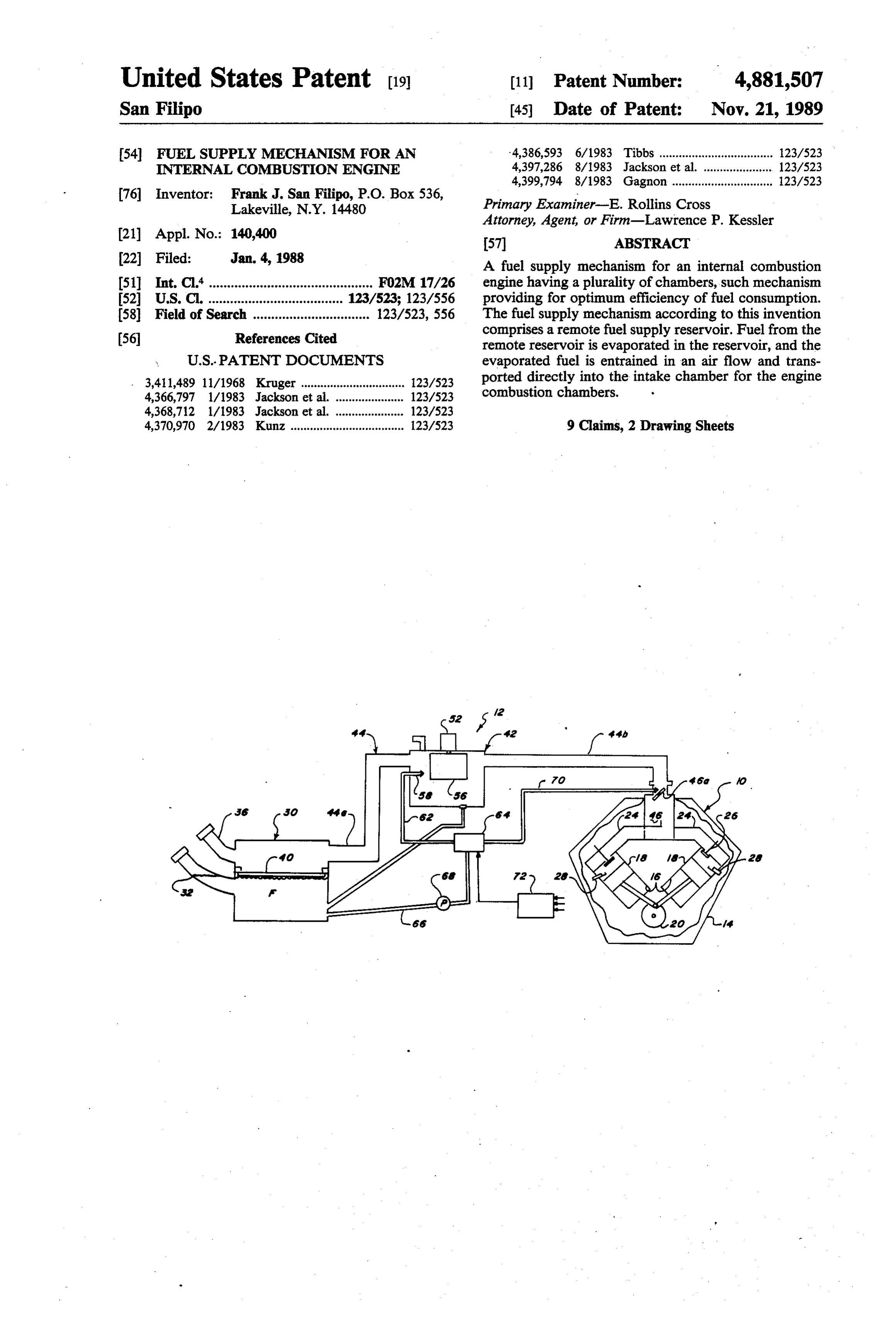
United States Patent (19) 11 Patent Number: 4,881,507 San Filipo (45) Date of Patent: Nov. 21, 1989 54 FUEL SUPPLY MECHANISM FOR AN 4,386,593 6/1983 Tibbs ................................... 23/523 INTERNAL COMBUSTON ENGINE 4,397,286 8/1983 Jackson et al. ... 123/523 4,399,794 8/1983 Gagnon ............................... 123/523 76 Inventor: Frank J. San Filipo, P.O. Box 536,
Lakeville, N.Y. 14480 Primary Examiner-E. Rollins Cross
Attorney, Agent, or Firm-Lawrence P. Kessler (21) Appl. No.: 140,400 57 ABSTRACT 22 Filed: Jan. 4, 1988 A fuel supply mechanism for an internal combustion (51 Int. Cl'............................................. F02M 17/26 engine having a plurality of chambers, such mechanism 52 U.S. C. ............... ... 123/523; 123/556 providing for optimum efficiency of fuel consumption. (58) Field of Search ................................ 123/523, 556 The fuel supply mechanism according to this invention (56) References Cited comprises a remote fuel supply reservoir. Fuel from the remote reservoir is evaporated in the reservoir, and the
3,411,489 11/1968 Kruger ................................ 123/523 ported directly into the intake chamber for the engine 4,366,797 1/1983 Jackson et al. ..................... 123/523 combustion chambers.
4,368,712 1/1983 Jackson et al. ..................... 123/523 4,370,970 2/1983 Kunz ................................... 123/523 9 Claims, 2 Drawing Sheets
Page 2
Drawing sheet — no readable text.
Page 3
Drawing sheet — no readable text.
Page 4
FUEL SUPPLY MECHANISM FOR AN INTERNAL DESCRIPTION OF THE PREFERRED
EMBODIMENTS
COMBUSTION ENGINE
Referring now to the accompanying drawings, FIG.
BACKGROUND OF THE INVENTION 5 1 schematically shows an internal combustion engine 10, and an associated fuel supply mechanism, designated
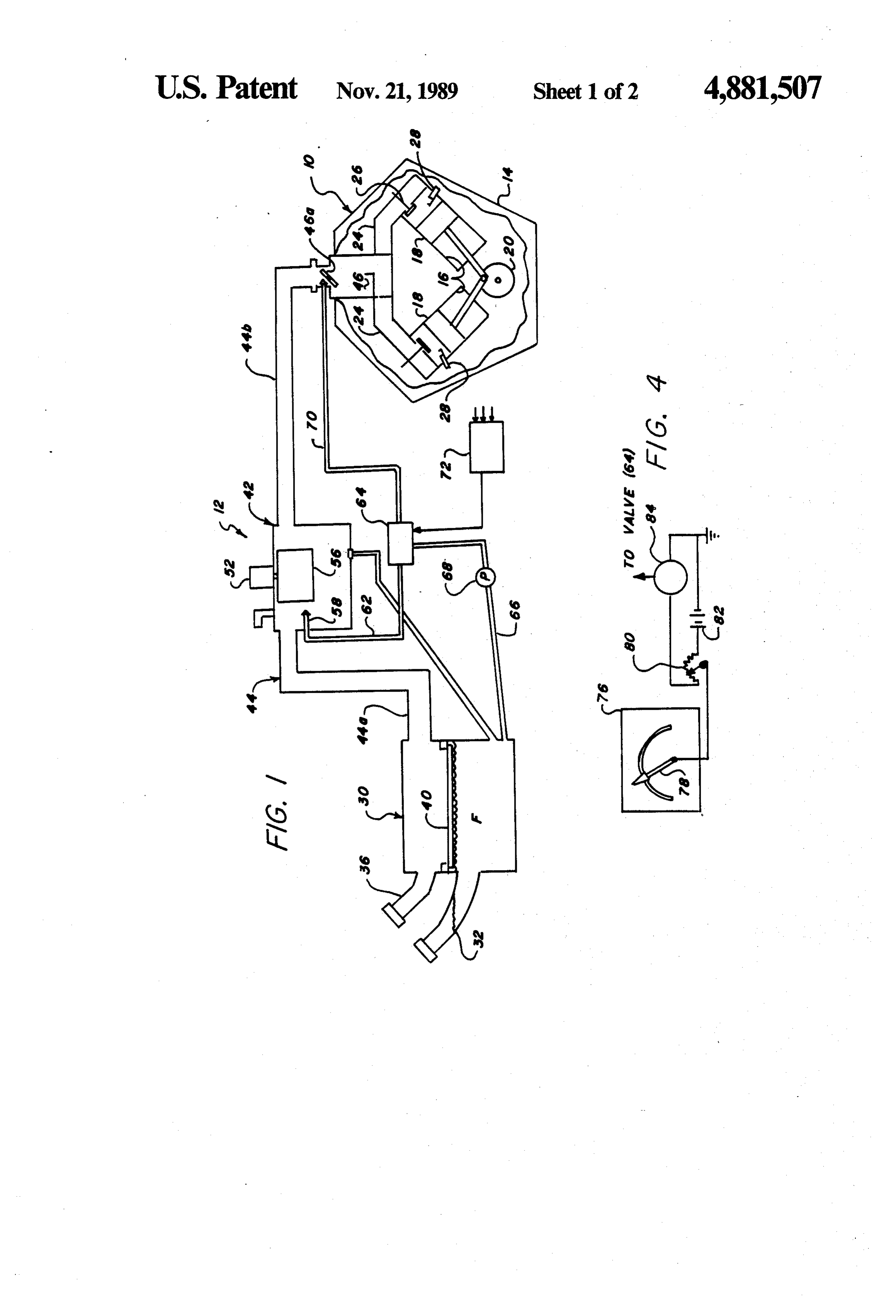
This invention relates in general to fuel supply mech generally anisms for internal combustion engines, and more par tion. The internalby the numeral 12, according to this inven ticularly to a fuel supply mechanism where fuel is va containing a plurality combustion engine 10 has a block 14 of combustion cylinders 16 (two porized in a remote reservoir for use in an internal com O shown) in which pistons 18 respectively reciprocate to bustion engine. rotate a drive shaft 20 in a well known manner. The For years fuel has been supplied to the standard inter cylinders 16 communiate with a fuel mixture intake nal combustion engine by a carburator which mixes raw chamber 46 via fuel mixture conduits 24 which respec fuel pumped from a fuel supply tank with air. The fuel tively run from the chamber 46 to each of the cylinders. Mair mixture is then sucked into the combustion cham 15 Ports 22 in the cylinders 16, respectively controlled by bers and ignighted by a spark to create the required valves 26, allow the fuel mixture to be delivered to the combustion reaction necessary to power the engine. It respective cylinders at appropriate times. Each cylinder has long been recognized that the carburator does not has a spark plug 28 associated therewith for ignighting provide for an efficient utilization of the fuel. the fuel mixture within the cylinders to create the con With the rapid rise in fuel prices it has become neces 20 trolled explosion for propelling the pistons 18 to rotate sary to develop improved mechanisms for getting fuel the drive shaft 20. While the engine 10 is shown as being to the combustion cylinders in a manner which provides of the type in which the cylinders are in a V-shaped for a more efficient use of the fuel. Recent efforts to orientation, the fuel supply mechanism 12 according to improve fuel economy have resulted, for example, in this invention is suitable for use with other engine con the development of a direct fueld injection engine 25 figurations and cylinder orientations, such as in-line or which eliminates the carburator. In such system, pres opposed for example. Moreover, while it is intended surized fuel is delivered to injectors which aspirate the that the engine 10 is to be used as the motive source for fuel into an air stream for delivery to the combustion a pasenger carrying vehicle, it is of course understood chambers. Since the fuel aspiration is capable of a more that the engine could suitably be used for many other finite control, fuel consumption efficiency is markedly 30 applications.
improved. However, a relatively significant portion of Controlled, efficient feeding of the fuel mixture to the the fuel still does not burn in the combustion chambers engine 10, is provided by the fuel supply mechanism 12 to provide motive energy and is therefore wasted. Thus according to this invention. The mechanism 12 includes fuel consumption efficiency is not optimized by the fuel -a remote reservoir 30 adapted to contain a primary injection system. 5 supply of fuel F. A first inlet conduit 32, connected to the reservoir 30, enables fuel to be added to the reser
SUMMARY OF THE INVENTION voir when the cap 34 is removed from the access end of such first conduit. A second conduit 36 is connected to
This invention is directed to a fuel supply mechanism the reservoir 30 for enabling air to be readily drawn into for an internal combustion engine having a plurality of the reservoir and across the fuel supply held therein. chambers, such mechanism providing for optimum effi- 40 ciency of fuel consumption. The fuel supply mechanism The the flow of air across the fuel supply causes a portion of fuel to evaporate into the air stream. The access end according to this invention comprises a remote fuel of the conduit 36 is covered with a suitable filter 38 to supply reservoir. Fuel from the remote reservoir is prevent contaminents, for example entrained in the air evaporated in the reservoir, and the evaporated fuel is 45 stream, from entering the reservoir 30. A float 40, entrained in an airflow and transported directly into the formed of a fibrous material for example, separates the intake chamber for the engine combustion chambers.
The invention, and its objects and advantages, will fuel-containing portion of the reservoir from the air stream drawn through the reservoir, while enabling the become more apparent in the detailed description of the air stream to carry out its evaporation function. preferred embodiments presented below. 50 Propulsion of the air stream to evaporate fuel from BRIEF DESCRIPTION OF THE DRAWINGS the reservoir 30 is provided by an evaporated fuel trans port assembly 42, which is shown in more detail in FIG.
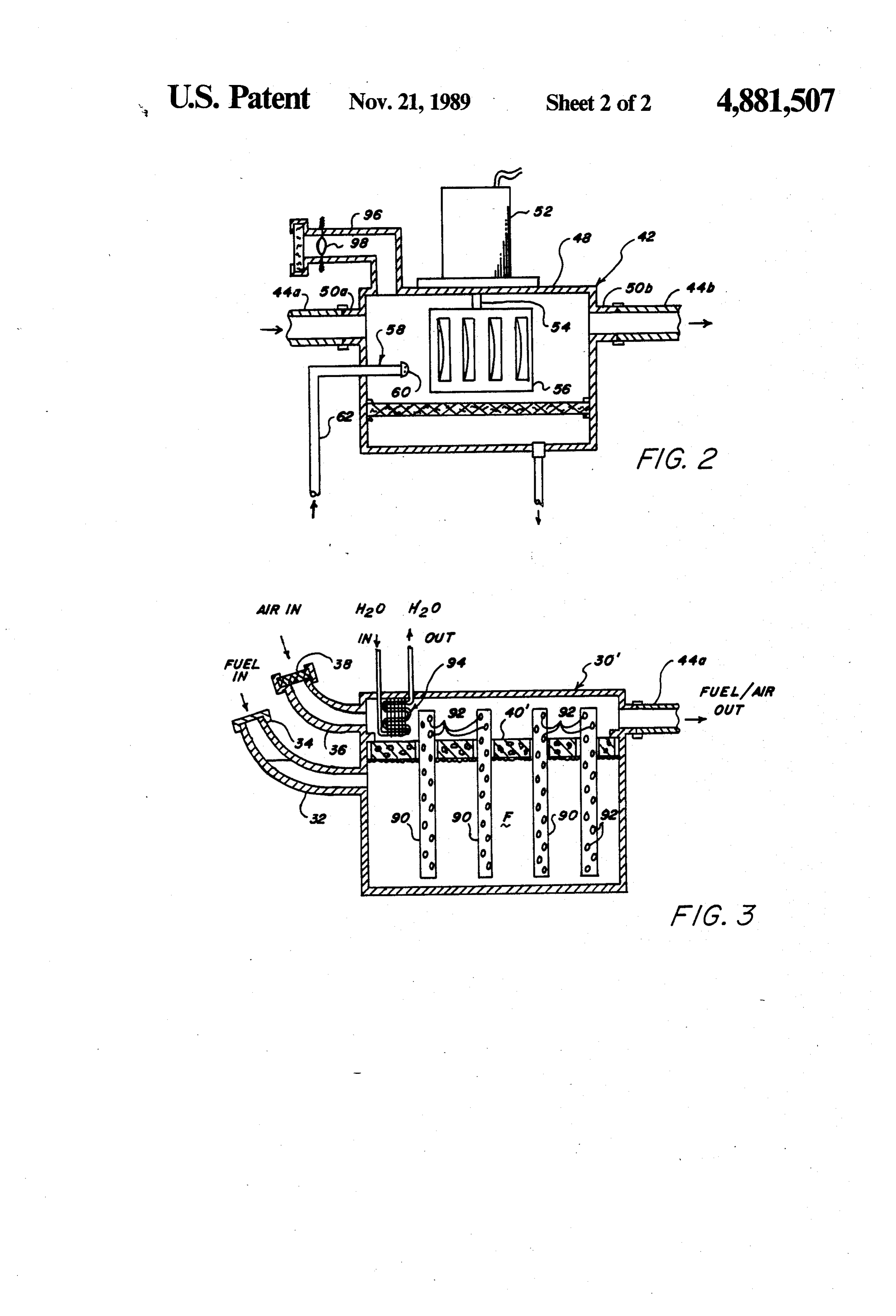
In the detailed description of the preferred embodi 2. The assembly 42 is located in conduit 44 which pro ments of the invention presented below, reference is vides flow communication between the reservoir 30 and made to the accompanying drawings, in which: 55 the intake chamber 46 of the engine 10 and may be FIG. 1 is a schematic illustration of an internal com positioned anywhere between the remote reservoir and bustion engine and an associated fuel supply mechanism the engine as is convenient. The transport assembly 42 according to this invention; includes a housing 48 having integrally formed bosses FIG. 2 is a side elevational view, in cross-section and 50a and 50b. A segment 44a of conduit 44 connects the on an enlarged scale, of an evaporated fuel transport 60 remote reservoir 30 to the transport assembly 42 at boss assembly for the fuel supply mechanism of FIG. 1; 50a, while a segment 44b of the conduit 44 connects the FIG. 3 is a side elevational view, in cross-section and intake chamber 46 to the apparatus 42 at the boss 50b. A on an enlarged scale, of an alternate embodiment of a motor 52 is mounted on an external portion of the hous remote fuel supply reservoir for the fuel supply mecha ing 48. The output shaft 54 of the motor 52 extends into nism of FIG. 1; and 65 the interior of the housing, through a suitable bearing FIG. 4 is a schematic illustration of an alternate em seal, and is coupled to a centrifugal impeller fan 56. bodiment of a control device for the fuel supply mecha When the fan 56 is activated by the motor 52, air is nism of FIG. 1. drawn from the intake 36 across the fuel supply F in the
Page 5
remote reservoir 30 and through conduit segment 44a microprocessor chosen for the unit 72. Of course, the into the interior of the housing 48. As the airflow passes control for the valve 64 can also suitably be accom across the the fuel supply F, it evaporates a portion of plished in other well known ways, such as for example the fuel so that the resulting air flow is actually a fuel by an operator adjustable mechanical linkage coupled /air mixture. The fan 56 forces the fuel/air mixture 5 to the valve.
through segment 44b of the conduit 44 into the intake The valve 64 may alternatively be controlled, at least chamber 46 of the engine 10, where it is thereafter selec as to the orientation of the engine 10, by an inclinometer tively supplied to the combustion chambers 16 to run 74 shown in FIG. 4. The body 76 of the inclinometer is the engine. A butterfly valve 46a is located in the throat associated with engine 10 so as to have the same orienta of the chamber 46. The purpose of the valve 46a is to O tion relative to the horizontal as the engine, in the direc automatically seal off the segment 44b of conduit 44 in tion of travel of the engine. Therefore, as the orientation case of engine backfire. of the engine changes (such as when the associated The motor 52 for driving the fan 56 is, for example, a vehicle is going up or downhills), the orientation of the variable speed brushless D.C. motor. This enables the body of the inclinometer will change in a proportional amount of air drawn through the reservoir, and thus the 15 manner. The gauge portion 78 attached to the inclinom amount of fuel evaporated, to be controlled by varying eter body 76 seeks a vertical orientation when the orien the motor speed. At the same time, such type motor will tation of the body changes. The portion 78 is coupled to not present a danger by creating sparks which could be a variable potentiometer 80 which controls the electical dangerous as possibly prematurely ignighting the fuel-. potential from an electrical power source 82 to an elec /air mixture. Under normal operating conditions, the air trically operated valve adjusting mechanism 84. The flow created by the fan 56 and drawn across the fuel mechanism 84 adjusts the valve 64 in an amount propor supply in the reservoir 30, has been proven to evaporate tional to the potential received by the mechanism. Ac sufficient quantity of fuel to adequately sustain combus cordingly, depending on the orientation of the incli tion in the engine combustion chambers 16. Accord nometer body, more or less potential is supplied to the ingly, the arrangement of the fuel supply mechanism 12 25 mecanism 84 to open or close the valve 64 appropri of this invention provides a for a fuel efficiency usage ately.
not found in prior fuel supply mechanisms. FIG. 3 shows an alternate arrangement, designated The proportions of air and fuel in the mixture sup generally by the numeral 30', for the remote reservoir of plied to the engine 10 must, of course, be adjustable to the fuel supply mechanism 12 according to this inven accomodate for differing operating conditions, such as tion. The remote reservoir 30' has a plurality of tubes 90 cold start-up or when added (less) power is needed for arranged within the housing thereof. The tubes 90, going up (down) hills or passing. To change the fuel/air which are supported by the fiborous float 40', are re ratio of the mixture, the transport assembly 42 includes spectively filled with a material which acts as a suitable a fuel diffuser 58. The diffuser 58 comprises a ported wick for the fuel in the reservoir. Additionally, the nozzle 60 located adjacent to the fan 56. Ifrequired, the 35 tubes have a series of openings 92 through their respec ports for the nozzle 60 may be adjustable in any well tive surfaces so that the wick material is exposed to the known automatic or manual manner. The nozzle is air flow over the the fuel supply. In this manner, more connected via a conduit 62 to an adjustable control fuel is exposed to the air flow so as to improve evapora valve 64. The valve 64 is, in turn, connected to the tion efficiency. Evaporation efficiency can still further remote reservoir 30 through a conduit 66, and through 40 be improved by elevating the temperature of the air a conduit 70 directly to the intake chamber 46 of the stream as it enters the reservoir 30'. Such heating of the engine 10. A fuel pump 68, located in the conduit 66 air stream is accomplished by passing the air stream pumps fuel from the remote reservoir 30 to the valve 64. over finned heating coils 94 supplied, for example, with The valve 64 is of the two-way type so as to be capable engine coolant.
of metering a desired flow of fuel into either of the 45 This invention has been described with particular conduits 62 or 70 for distribution to the nozzle 60 or the reference to preferred embodiments thereof, but it will engine intake chamber 46 respectively. An intake 96, be understood that variations and modifications can be having a spring-urged butterfly closure valve 98 for effected within the spirit and scope of the invention. example, enables additional air to be drawn into the I claim:
housing 48 of the assembly 42 if required to alter the 50 1. A fuel supply mechanism for an internal combus ratio of the fuel/air mixture. tion engine having a plurality of combustion chambers, As noted above, under certain operating parameters, said mechanism comprising:
the fuel supply mechanism 12 must deliver a portion of a remote reservoir adapted to contain a primary sup raw fuel directly to the nozzle 60 or to the engine intake ply of fuel;
chamber 46. By accurately controlling the opening of 55 means, located in said remote reservoir, for evaporat the valve 64, the efficiency in fuel utilization can be ing fuel in said remote reservoir into an air stream dramatically improved. This is because, as to raw fuel moving therethrough; and utilization, only that amount of fuel which is actually means for transporting said air stream containing needed for particular operating parameters is used, all such evaporated fuel from said remote reservoir other fuel requirements being supplied by the mecha 60 directly into said combustion chambers of said nism 12 in vaporized form. Control of the valve 64 is internal combustion engine, said evaporated fuel accomplished by, for example, an electronic micro transporting means including a conduit connected processor based unit 72, which automatically senses at one end to said remote reservoir and at the oppo engine operating parameters and, according to a pro site end to an intake chamber for said combustion gram for the microprocessor, appropriately sets the 65 chambers of said engine, a housing located in said opening of the valve. The architecture for the program conduit intermediate said remote reservoir and said is of course a well known skill in the art of microproces intake for said combustion chambers, and fan appa sor programing and is dependent upon the particular ratus associated with said housing for moving
Page 6
evaporated fuel through said conduit to said com 7. The invention of claim 1 further including means bustion chambers. for selectively directing a controlled amount of fuel into 2. The invention of claim 1 wherein said fuel evapo said housing of said transport means adjacent to said rating means includes means for directing a flow of air centrifugal fan apparatus and said intake for said com through said remote reservoir, over a primary supply 5 bustion chambers of said engine.
of fuel to evaporate a portion thereof and entrain such 8. The invention of claim 7 wherein said selective fuel evaporated fuel in such air flow. directing means includes a fuel pump, a first conduit 3. The invention of claim 2 wherein said air flow connecting the intake of said fuel pump to said remote directing means further includes means for heating such reservoir, a fuel metering control valve, a second con air flow prior to directing such air flow through said O duit connecting the output of said fuel pump to said remote reservoir to improve the evaporation efficiency control valve, a third conduit connecting said controll thereof. valve to said transport means housing, and a forth con 4. The invention of claim 2 wherein said remote reser duit connecting said control valve to said intake for said voir includes at least one wick extending from the sup combustion chambers of said engine, and means, re ply of fuel into the path of air flow for bringing an 15 sponsive to engine operating requirements, for control increased amount of fuel directly into contact with such ling said fuel metering control valve to provide supple air flow. mental fuel flow to said transport means housing or said 5. The invention of claim 1 wherein said fan appara intake for said combustion chambers. tus includes a centrifugal fan having a motor mounted 9. The invention of claim 8 wherein said control externally of said housing, an output shaft of said motor means includes an inclinometer gauge associated with extending through a wall of said housing into the inte said engine, said inclinometer gauge being operatively rior thereof, and an impeller mounted on said output connected to said control valve to set said valve depen shaft in the interior of said housing. dent upon the orientation of said engine relative to 6. The invention of claim 5 wherein said motor is a horizontal.
variable speed, brushless D.C. motor. 25 k
Provenance
- Collection
- Cited prior art
- Original PDF
- patentimages.storage.googleapis.com →
- Filed
- 1988-01-04
- Pages
- 6
- Method
- pdftotext (the PDF's own text layer) + pdftoppm 300dpi page scans
- Source
- Google Patents bibliographic record
- Granted
- 1989-11-21
- Inventors
- Frank J. San Filipo
- Transcribed from
- patentimages.storage.googleapis.com →