patent · US4368712
Vaporous gasoline fuel system and control therefor
18 January 1983
Page 1
United States Patent (19) 11 4,368,712 Jackson et al. 45) Jan. 18, 1983 (54 WAPOROUS GASOLINE FUEL SYSTEMAND 4,074,666 2/1978 Pierce ............................. 261/19 R CONTROL THEREFOR 4,076,002 2/1978 Mellavist. 4,138,979 2/1979 Taplin ................................. 123/489 75 Inventors: Kenneth A. Jackson, Wooster; 4,153,021 5/1979 Hattori ................................ 123/440 George I. Arndt, Loudonville; James 4,177,779 12/1979 Ogle .
L. Maynard, Cuyahoga Falls, all of 4,296,710 4/1980 Lehar .................................. 123/523 Ohio 4,200,064 4/1980 Engele.
73) Assignee: W.G.A.S., Inc., Loudonville, Ohio
Primary Examiner-Ronald H. Lazarus 21 Appl. No.: 173,605 Attorney, Agent, or Firm-Baldwin, Egan, Walling & 22 Fed: Aug. 1, 1980 Fetzer 51 Int. C.’...................... F02M 17/18; FO2M 17/22 57 ABSTRACT 52 U.S. C. .................................... 123/523; 123/522; A fuel system and electronic control therefor which is 123/440; 261/36 A; 261/104 especially designed for use with an internal combustion 58) Field of Search ....................... 123/522, 523, 524; engine or the like in which said fuel system is operable 261/36 A, 119 R, 79 R, 102, 104 to provide fuel fumes or vapor to the engine from a 56 References Cited source of liquid ignitable vaporizable fuel, such as gaso
crease the efficiency of the engine and thus substantially 983,646 2/1911 Roberts et al. . increase the per gallon mileage rate for the engine when
1,403,848 1/1922 Forrest ................................ 123/522 used in an automotive vehicle or the like, and one using 1,470,204 10/1923 Swartz . liquid fuel as the original fuel source. The system incor 1,828,134 10/1931 Fahrney ............................ 26A36 A porates an electronic control operable to monitor the 2,400,821 5/1946 Goode .............................. 26/36A combustion of the vaporizable fuel and which control is 3,325,152 6/1967 Wahnish ......................... 261/119 R responsive to a change in engine demand for said fuel to 3,338,223 8/1967 Williams . maintain the optimum ratio of vaporized fuel and air in
3,790,139 2/1974 Stephensen . the mixture delivered to the engine for combustion.
3,999,526 12/1976 Asfar . 18 Claims, 8 Drawing Figures
Sardaction
C CoNROLLER / A2
Page 2
Drawing sheet — no readable text.
Page 3
Drawing sheet — no readable text.
Page 4
Drawing sheet — no readable text.
Page 5
Drawing sheet — no readable text.
Page 6
SENSOR VOLTAG
A R valve closes Vs sensor Voltage gh ANG
Yotoe stops
At This voltage tra V-tai - slow V controls speed of C Vco)
vAX 2ATE 5-oWNER 5Topped soyn
Page 7
engine and hence substantially increasing the mileage
WAPOROUS GASOLINE FUEL SYSTEMAND rate per gallon of liquid fuel. CONTROL THEREFOR In actual testing of one embodiment of system incor porating the present invention with an internal combus
This invention relates to a new and novel fuel system tion engine in an automobile, the mileage rate obtained and more particularly to a fuel system especially de per gallon with liquid leaded gasoline as the source of signed for use with internal combustion engines or the ignitable fuel, has been of the order of at least 400 per like, and which fuel system is operable therewith to cent greater than that which has been heretofore obtain provide fuel fumes to the engine from a source of liquid able using liquid gasoline which is directly burnable in ignitable vaporizable fuel, such as gasoline, and of suffi 10 the engine.
cient quantity, whereby to significantly increase the For example, testing of the present system has been efficiency of the engine, to thus substantially increase undertaken with a 1975 Cadillac wherein the mileage the per gallon mileage rate for the engine when used in rate per U.S. gallon of fuel obtained has been in the an automotive vehicle or the like, and using the liquid magnitude of 45-48 miles per gallon with liquid leaded fuel as an original fuel source. This fuel system is pro 15 gasoline as the fuel source.
vided with an electronic monitoring and control system It is, therefore, a primary object of the present inven especially operable to monitor the combustion of the tion to provide a fuel system especially designed for use vaporized fuel and air delivered to the engine and with an internal combustion engine utilizing liquidignit which is responsive to a change in the engine demand able fuel as the fuel source, and wherein the fuel system for said fuel to maintain the optimum ratio of fuel and 20 is operable to generate fuel fumes from said liquid fuel air in said vaporized fuel mixture delivered to the en and to provide a sufficient quantity of the same to the gine for combustion. engine, so as to substantially increase the operating.
BACKGROUND OF THE INVENTION
efficiency of the engine.
Another object of the invention is to provide a fuel
It is recognized in the art that the efficiency of the 25 system especially designed for use with an internal com typical internal combustion engine in present use in bustion engine of an automotive vehicle adapted to automotive vehicles, and the like is approximately utilize liquid ignitable fuel and which system is operable twenty-five percent or less when using liquid fuel such to generate fuel fumes in an improved manner from the as gasoline or other like ignitable fuels, such as for in liquid fuel, and to provide fumes of sufficient quantity to stance pentane, hexane, heptane, octane, nonane, dec 30 the engine, whereby to significantly increase the effi ane, undecane, dodecane, tetra decane, hexadecane, ciency of the engine, to thus substantially increase the octadecane and crude oil. automotive vehicle per gallon mileage rate of the liquid Typical prior art fuel systems are exemplified in U.S. fuel.
Pat. Nos. 983,646; 1,470,204; 3,338,223; 3,749,376; 35 Another object of the present invention is to provide 3,854,463; 4,204,485; 4,200,064; 3,790,139; 3,999,526; an electronic control for use with the fuel system and 4,074,666; 4,076,002 and 4,177,779. which is operable to monitor the combustion of the In the use of any such liquid fuel with an associated vaporized fuel by the engine and which control is re internal combustion engine it is well recognized that a sponsive to a change in engine demand to maintain the substantial percentage of said fuel is not utilized by the optimum ratio of the mixture of vaporized fuel and air engine for power generation, but instead is expelled delivered to the engine. ... . from the engine and/or burned or consumed in the Still another object of the present invention is to exhaust system thereof. provide a fuel system as hereinabove referred to which In applicant Kenneth A. Jackson's pending U.S. pa is operable at atmospheric pressure and which utilizes tent applications Ser. Nos. 86,323, filed Oct. 19, 1979 the vacuum or suction generated by the engine, to pro and 129,345, filed Mar. 11, 1980, and in applicants 45 vide the fuel fumes to the engine.
Kenneth A. Jackson and George I. Arndt's copending Other objects and advantages of the invention will be: application Ser. No. 151,170, filed May 19, 1980, there is apparent upon reference to the following description disclosed a novel fuel system which will materially taken in conjunction with the accompanying drawings, increase the efficiency of an internal combustion engine, which illustrate preferred embodiments thereof. and the prior art identified therein is incorporated 50 BRIEF DESCRIPTION OF PREFERRED herein, without specifically listing the same. The pres EMBODIMENT ent invention is an improvement of a system of the general type disclosed in Ser. No. 151,170. The fuel system of this invention provides fumed fuel. BRIEF DESCRIPTION OF THE INVENTION from a source of liquid fuel such as gasoline" or like 55 liquid ignitable fuel, many of which are hereinabove.
Briefly, the invention provides a fuel system for use referred to, to an internal combustion engine. with an internal combustion engine or the like wherein As one preferred embodiment, it is herein described, fuel fumes are generated from a liquid source of ignit for use with an automobile wherein "fumed gasoline able fuel such as gasoline, or similar liquid vaporizable fuel' is generated in an auxiliary or fume tank, which fuel, and presented in a fumed state to the engine for coacts with a main liquid fuel tank, and is mixed with consumption and power conversion therein, and air, and then supplied to the carburetor of the engine, wherein the system is provided with improved means for powering the latter. The fume tank is controllably for fuming the liquid fuel. vented or connected to atmosphere, to provide suitable Novel arrangements of fume tanks are disclosed for quantities of air for fuming and mixing with the vapor use in the fuel system. - 65 ous fuel, and improved means are provided for accom Substantially all of the fumed fuel presented to the plishing the fuming of the liquid fuel. The present sys engine is consumed therein for power conversion, thus tem incorporates an control which is operable to moni resulting in substantially, increasing the efficiency of the tor the exhaust gases which result from the combustion
Page 8
of the vaporized fuel and air mixture delivered to the internal combustion engine in varied environments such engine and which control is responsive to a change in as tractors, stationary power units, off-the-road equip engine demand as sensed in said gases to correspond ment, and the like.
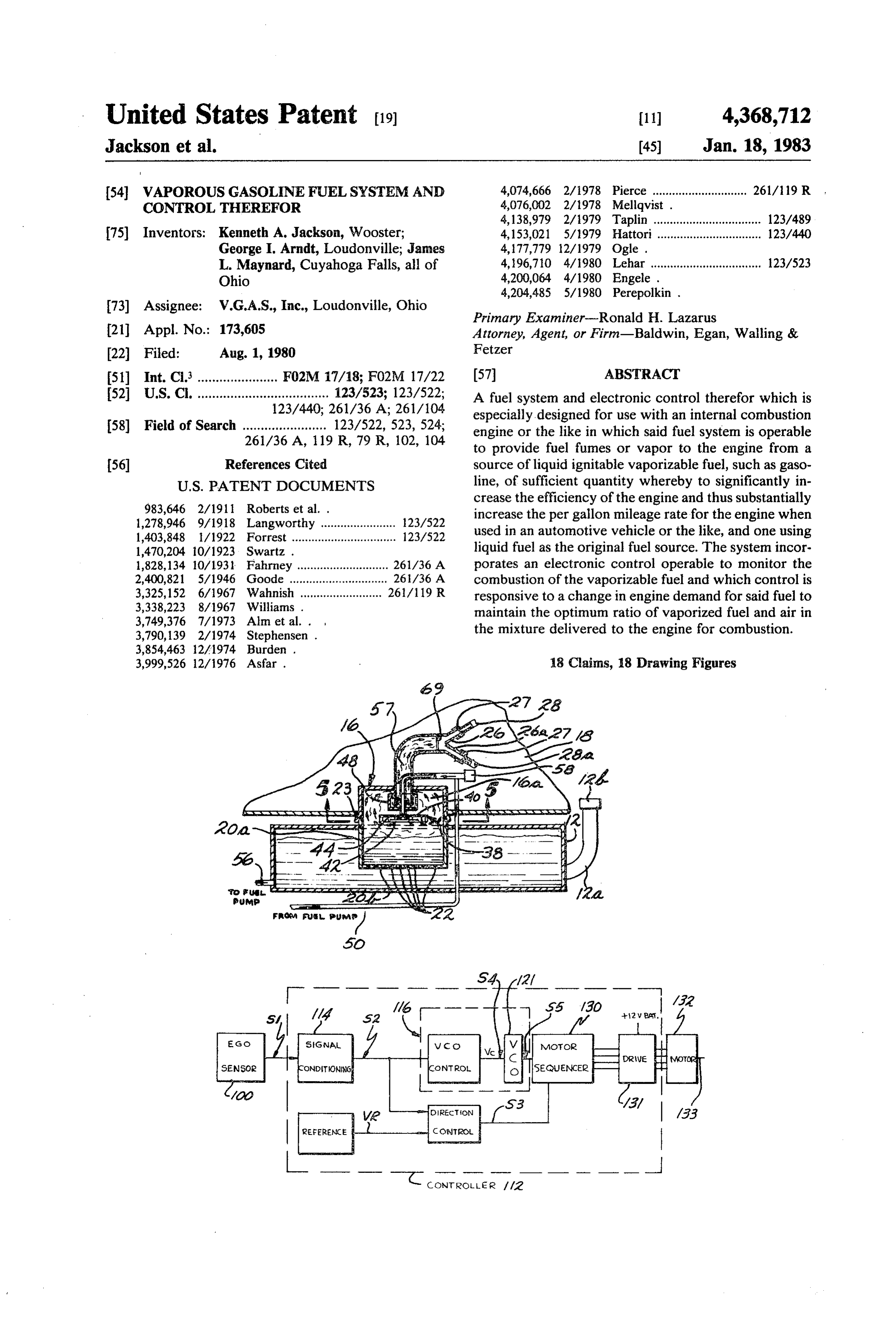
ingly modify the air delivered to said mixture being thus As herein illustrated, and as also disclosed in appli operable to maintain the optimum ratio of the vaporized cants' copending application Ser. No. 151,170, filed fuel and air in said mixture. May 19, 1980, a typical automobile vehicle V is shown BRIEF DESCRIPTION OF THE DRAWINGS in FIG. 1 equipped with an internal combustion engine 10 designed to burn liquid ignitable fuel supplied by a
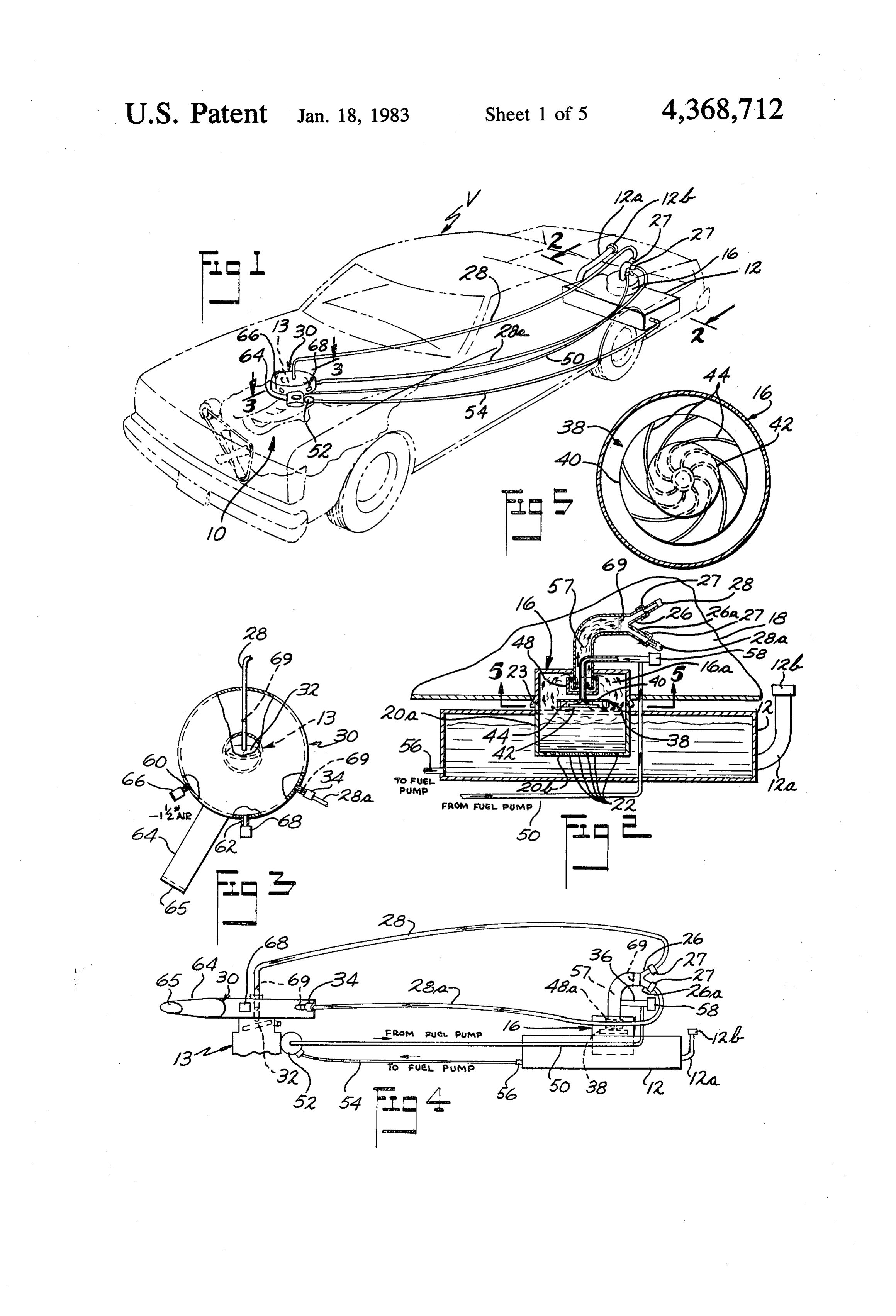
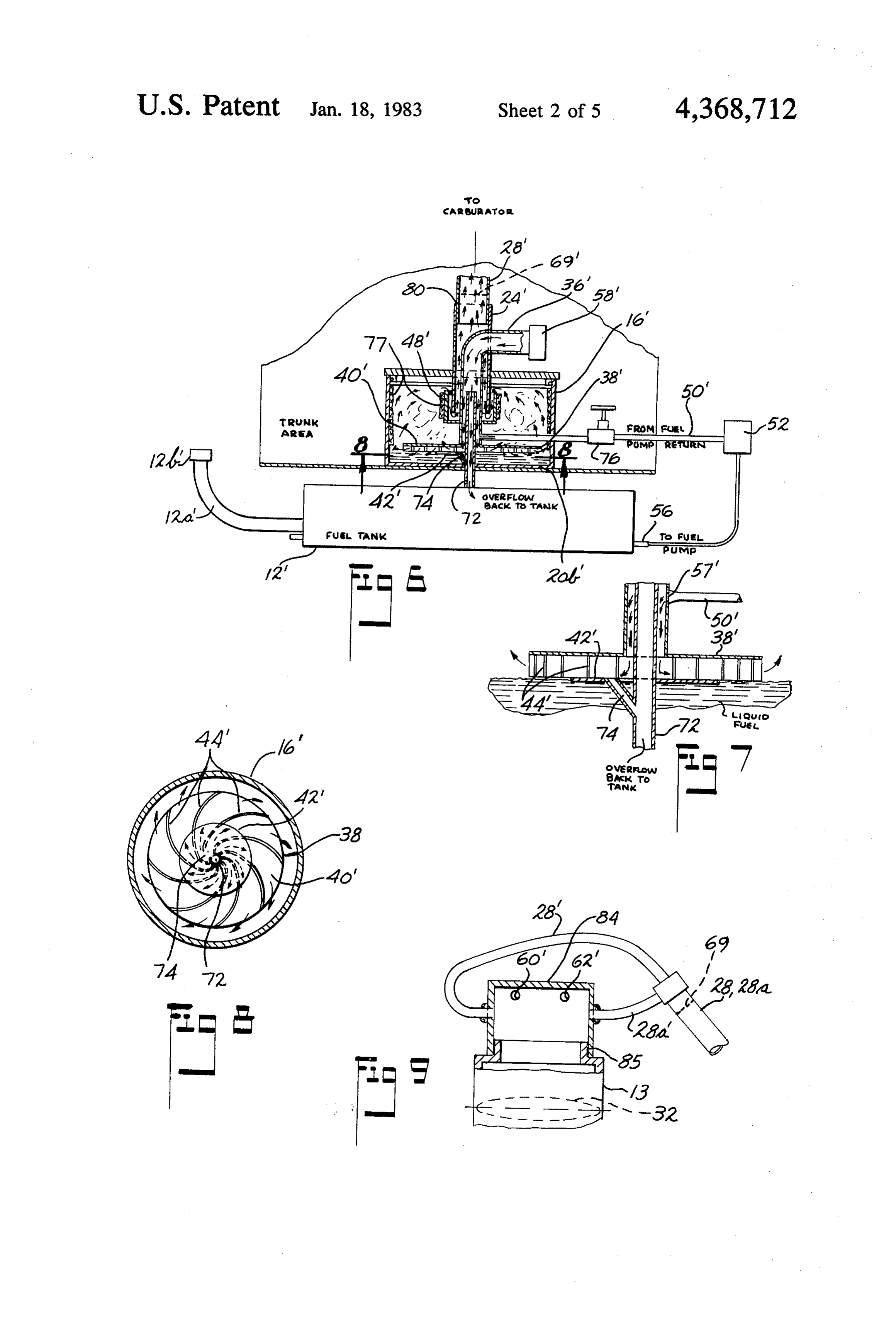
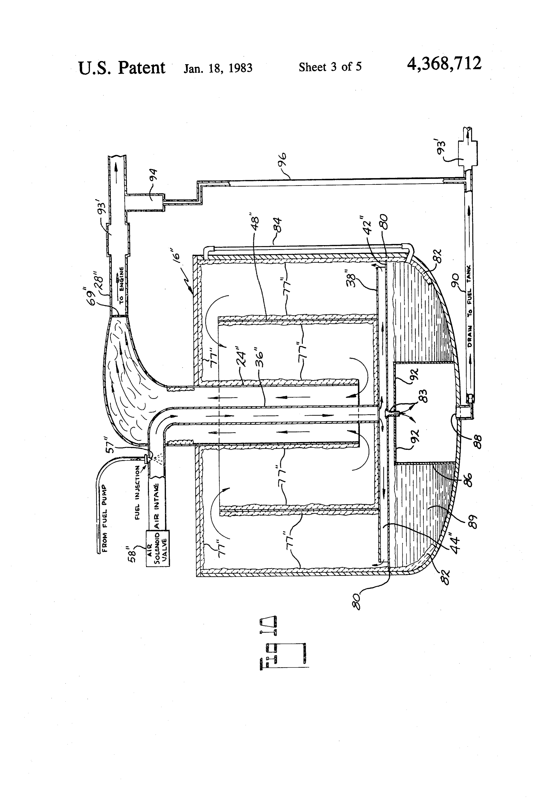
FIG. 1 is a perspective view illustrating a typical more or less conventional fuel tank (e.g. tank 12 having automobile in phantom, with the fuel system of the O liquid fuel inlet 12a and conventional vented cap 12b) present invention interconnected between the tank con for providing liquid fuel such as gasoline or any other taining the liquid fuel and the carburetor of the engine; liquid vaporizable ignitable fuel, to the carburetor 13 of FIG. 2 is a view taken generally along the plane of said engine.
line 2-2 of FIG. 1 and illustrates in section the rear As aforementioned, with the fuel such as gasoline trunk area of the automobiles and the main gasoline tank 15 being supplied to the engine 10 in its liquid state, the located therebelow, with the auxiliary or fume tank engine only uses about 25-30 percent of said fuel for projecting upwardly from the main tank and extending power conversion whereby the major part of said fuel is into the trunk space; wasted and emitted in various well known pollutant FIG. 3 is a view looking along the plane of line 3-3 forms from said engine.
of FIG. 1 showing a partially broken, enlarged plan 20 As aforementioned, the fuel system of the present view of the carburetor and associated air cleaner hous invention overcomes this deficiency by providing ignit ing, and of connections thereto, as embodied in the fuel able fuel in its "fumed state' such that substantially all system of the present invention; of the delivered fuel to said engine is utilized for power FIG. 4 is a generally diagrammatic elevational view conversion.
of the fuel system of the invention connecting the car 25 To accomplish this, a fuel fume tank or auxiliary tank buretor of the vehicle engine with the source of liquid identified at 16 which is generally cylindrical in its fuel; present configuration, coacts in the upright position FIG. 5 is an enlarged, sectional view taken generally with the conventional fuel tank 12 located below the along the plane of line 5-5 of FIG. 2, looking in the trunk space 18 (FIG. 2) of the vehicle, and with its direction of the arrows, and illustrating the underside of 30 (member 16) lower end projecting into the interior of the diffuser mechanism in the auxiliary or fume tank of tank 12, so as to be disposed in submerged relation with the system. the anticipated level 19 of liquid fuel in main tank 12. FIG. 6 is a sectional view generally similar to FIG. 2, Tank 16 in the embodiment illustrated comprises top but illustrating another embodiment of system espe wall 20, side wall portion 20a and bottom wall 20b, with cially as concerns the auxiliary or fume tank and associ 35 such bottom wall, in the embodiment illustrated having ated main liquid fuel tank; a plurality of openings 22 therein, thus communicating FIG. 7 is an enlarged detail view of the auxiliary tank the interior of tank 16 with the interior of main tank 12, of FIG. 6 illustrating an overflow arrangement. and thus establishing the liquid fuel level in tank 16 at FIG. 8 is a view generally similar to FIG. 5, but taken substantially the same level as that of the liquid fuel in along the plane of line 8-8 of FIG. 6; 40 main tank 12. Tank 16 is received in the complementary FIG. 9 is a vertical, sectional enlarged view of an opening 23 formed in the top wall of main tank 12 in other embodiment illustrating a cap rather than an air sealed relation, either by adequate gasketing means or filter housing, for use with a conventional internal com by permanent welds securing tank 16 to tank 12. bustion engine carburetor, for controlling the air intake In its present configuration, tank 16 is about 16" in its of the carburetor during the supplying of fumed fuel 45 external diameter, to define a fume chamber 16a therein. thereto from an auxiliary or fume tank system of the One end of a collector member or tube 24 is secured. type of FIG. 2 or of the type of FIG. 6; as at 24a by any suitable means, such as, for instance, FIG. 10 is an enlarged view of an auxiliary or fume welds, to the top wall 20 (in the embodiment illustrated) tank generally similar to that of FIG. 6, but illustrating of the auxiliary or fuming tank 16, with such member 24 a further embodiment of fume tank which includes 50 projecting interiorly of the fuming tank 16, and being means for further aiding in vaporizing the liquid fuel open at its bottommost end, for passage of fumed fuel and in removing droplets of liquid fuel from the fumed air mixture thereinto from the fuming tank. air-fuel mixture prior to its passing from the fume tank; Member 24, in the embodiment illustrated, is of arcu FIG. 11 is a schematic diagram of the electronic ate configuration in side elevation, as can be best seen in control incorporated for use with the present fuel sys 55 FIG. 2, and at its distal end comprises a pair of branch tem; conduit sections 26, 26a, which have coupling means 27 FIG. 12 is a schematic diagram illustrating the con coacting therewith such as, for instance, threaded cou trol circuitry of the control of FIG. 11; and pling means, for coupling member 24 to a respective FIG. 13 (A-F) is a chart illustrating electrical signal line 28, 28a, waveforms which are present at various locations in the Line 28 is directed to the carburetor 13 passing electronic control. through a tight fitting opening in the conventional air DESCRIPTION OF PREFERRED cleaner housing 30 mounted on the carburetor, and with EMBODIMENTS line 28 terminating just above the conventional butter fly valve 32 located in the carburetor throat, thereby
While the fuel systems illustrated are particularly 65 providing for passage of fumed fuel-air mixture from adapted for use with an internal combustion engine in the collector member 24 to the carburetor. Line 28a an automotive vehicle type of environment, it is also passes from the collector 24 to coupling 34, mounted to contemplated that said system may be adaptable to an the conventional air cleaner housing 30, thereby provid
Page 9
ing a further passage for the transmission of additional A conventional, normally closed, air check valve 58 fumed fuel-air from the collector 24 to the carburetor. (FIGS. 2 and 4) coacts with the air inlet line 36 and is Collector tube 24 in the specific embodiment illus intended to be actuated to its open condition in response trated, is preferably approximately three inches in inter to the pressure in the fuming tank 16 reaching a nega nal diameter, while supply line 28 has an internal diame 5 tive pressure (vacuum) of approximately minus one ter of preferably approximately 1', and line 28a, has a pound of mercury as read on a conventional automotive corresponding diameter of approximately 3". Such lines vacuum gage, thus connecting the interior of the fuming 28, 28a are capable of providing sufficient fumes to tank 16 through the air inlet pipe 36 to atmosphere. In carburetor 13 for powering the engine. actual practice this magnitude of negative pressure Extending from exteriorly of collector member 24 O (vacuum) is substantially immediately realized upon the and passing through the wall thereof in sealed relation engine 10 being initially actuated or "turned over' as is ship, is an air inlet conduit 36, which extends down referred to in the art.
wardly through the downwardly extending collector Referring now to FIG. 3, the circular wall of the air pipe 24 below open end thereof, with pipe 36 having a filter housing member 30 is provided with two air entry diffuser member 38 secured thereto just above the level 5 ports 60 and 62 respectively. The conventional air in 19 of liquid fuel in auxiliary or fuming tank 16. take chute 64 on the air cleaner is blocked, as at 65, so Diffuser member 38, in the embodiment illustrated, that air cannot be drawn thereinto as is conventionally comprises an upper plate 40 and a lower plate 42 (FIG. done with an internal combustion engine. Port 60 is 5) with the distal end of air inlet pipe 36 being disposed connected to a normally closed conventional air check in vertically spaced relation above the lower plate 42 so valve 66, while port 62 is coupled to a normally closed that as air (and also fuel as will be hereinafter described) conventional air check valve 68. Valve 66 is adapted to passes downwardly through the pipe 36, it impinges open in response to pressure in the throat of the carbu against the upper surface of lower plate 42. Extending retor reaching a negative pressure (vacuum) of approxi generally radially outwardly from the vertical axis of mately one and one-half pounds of mercury, thus cou plate 42 commencing generally adjacent the periphery 25 pling the closed air cleaner housing to the exterior air of lower plate 42, are a plurality of arcuate vanes 44 so shortly after the engine is "turned over' or actuated, that the air and fuel passing into diffusing member 38 is thus permitting air to pass through the valve 66 and twirled or given a vortex effect as it streams outwardly "leaning out” the fuel-air mixture of fumed fuel being through the diffusing member 38 and across the con supplied via lines 28, 28a to the carburetor. In the pres fronting surface of the liquid fuel in auxiliary tank 16, 30 ent system, as will be hereinafter described, the air thus fuming the fuel and creating a relatively rich mix check valve 68 is positively controlled by the electronic ture of fuel and air, which is then drawn upwardly by control of the instant system to variably regulate the the engine vacuum, as will be hereinafter discussed. amount of air entering the carburetor for mixing with As the fumed fuel-air mixture is drawn upwardly in the fuel-air mixture, thus furnishing further outside or chamber 16a of fume tank 16, it passes through a baffle 35 atmospheric air to the carburetor. If needed, one or arrangement 48, which may be supported on aforemen more additional air check valves (not shown) may be tioned inlet pipe 36, such baffle comprising a cup-like used in the manner air check valve 68 is incorporated in member 48a which opens upwardly so that the fumed the fuel system of the aforementioned co-pending appli fuel-air vapor has to pass upwardly over the open top of cation Ser. No. 151,170 which valve 68 is coupled to the cup-shaped baffle and then downwardly to pass into 40 carburetor port 62 and adapted to open when the pres the lower. open mouth of collector member 24, and sure in the carburetor throat reaches a negative pressure aiding in removal of only liquid droplets of fuel from (vacuum) of approximately five pounds of mercury to the fumed fuel-air mixture. admit additional air into the carburetor. Air inlet pipe 36 preferably has an interior diameter of In operation the fume fuel system of the FIGS. 1 approximately one inch. Branching off from air inlet 45 through 5 system is preferably as follows. pipe 36 and in communication therewith is a liquid fuel Assuming that the engine 10 is off, or at rest condi pipe or conduit 50 of conventional internal diameter tion, a certain quantity of fuel fumes is being generated size coming from the output port of the conventional in the fuming tank 16 due strictly to the fact that there fuel pump 52 (FIG. 4) of the conventional internal com is liquid fuel therein. In this rest condition, the air check bustion engine 10. The input port of the fuel pump 52 is 50 valves 58, 66 and 68 are in closed condition, and the connected by means of conventional conduit line 54 butterfly valve 32 in the carburetor throat is likewise in (FIGS. 1 and 4) to the conventional outlet port 56 on generally closed position.
the main fuel tank 12. Fuel lines 50 and 54 preferably When the engine is turned over either manually, or have an internal diameter in the embodiment illustrated by the typical battery-powered starter used in conven of approximately ". . 55 tional present-day automotive systems, the initial crank A shower head or liquid diffusing screen 57 of con ing of the engine will generate a vacuum in the fuming ventional known type may be provided either at the tank 16 and in the air inlet pipe 36 as well as in the connection of fuel line 50 to air inlet line 36, or in the engine manifold, and in carburetor 13, when the butter alternative at the distal end of air inlet line 36, so that fly valve 32 is opened through the conventional foot the liquid fuel as it is mixed with the air being inserted 60 control accelerator or throttle (not shown), or by any into the diffuser member 38 via line 36, is broken into a other means, thus causing the vacuum to go to about fine mist, thus facilitating the fuming of the liquid fuel minus one pound of mercury in the carburetor as well as and enriching the fuel-air mixture with fumes of the in the lines 28, 28a and in the aforementioned fuming liquid fuel as compared with liquid fuel droplets. The tank 16 and air inlet 36, and thus resulting in the air impacting of the lower plate 42 in diffuser 38, by the 65 check valve 58 to outside air, permitting air from atmo sphere to flow into inlet pipe 36. At the same time, the cranking of the engine causes the fuel pump 52 to pump liquid fuel via fuel line 50 into air inlet pipe 36 through
Page 10
the misting connection 57, thereof, thereby supplying a nectable to an existing main fuel tank without substan combined fuel-air mixture to the diffuser member 38, tial alteration of the latter and an overflow arrangement whereupon the fuel mixture whirls in cyclonic fashion is provided for causing fuel inserted into the air inlet outwardly from the center of the lower baffle, or abut line to be returned to the main tank when it gets to a ment plate 42, to pass across the surface of the liquid predetermined level in the auxiliary fuming tank. In this fuel in auxiliary tank 16 upwardly past the baffle ar arrangement, like reference numbers have been utilized rangement 48, and into the open bottom end of the when referring to the component parts thereof, except collector tube 24. that the prefix prime () has been added thereto. The cyclonic, or whirling effect of the diffuser38 aids In this arrangement, the auxiliary fuming tank 16 in elimination of liquid droplets from the fuel-air mix O includes a non-perforated bottom wall 20b', but which ture abutting against the abutment plate 42, thereby has a pipe or conduit member 72 extending through maintaining the fuel-air mixture being supplied to the such bottom wall 20b' in sealed relation therewith, and engine in vaporous condition, as well as enhancing the which extends downwardly to communicate at its vaporization of the liquid fuel. Such fuei-air mixture, lower end with the interior of the main fuel tank 12" of passing upwardly through the baffle 48, likewise aids in 15 the vehicle. Coacting with upright pipe 72 is an over removal of any liquid droplets in the fuel-air mixture to flow pipe section 74 which branches off from pipe 72 further aid in increasing the efficiency of the engine. and extends a predetermined distance above the bottom From collector chamber 24, the fuel may pass surface of the auxiliary tank 16’ and in this embodiment through the fuel supply lines 28, 28a to the carburetor, opens onto the upper surface of bottom baffle plate 42 whereupon the fuel in the piston firing chambers of the 20 of diffuser member 38. Thus it will be seen that in the engine 10 is ignited, to cause the engine to fire. As the event that the fuel level in auxiliary tank 16 gets up to comparatively rich fuel-air vaporous mixture is passed the entry mouth pipe 74, the fuel flows down through into the carburetor, due to the vacuum caused by crank branch pipe 74, through pipe 72 to the interior of main ing the engine, the atmospheric air inlet check valve 66 fuel tank 12".
opens to mix further at approximately a minus one and 25 The air inlet pipe 36 in this embodiment extends from one-half pounds of mercury, to "lean' out the fuel as it exteriorly of the collector pipe or member 24 through passes through the throat of the carburetor to the piston the wall thereof in sealed relationship and extends chambers. downwardly to terminate at the upper plate member 40' Upon firing of the engine, the atmospheric air check of diffuser member 38'. In other respects, the diffuser valve 68 under control of the electronic control of 30 member 38' is generally similar to that aforediscussed in FIGS. 11-13 is initially opened thereby to a "preset connection with diffuser member 38 of the first de open position' as will be later more fully explained to scribed embodiment. The air inlet pipe 36 has a conven further lean out the comparatively rich vapor being tional air check valve 58' coacting therewith in a similar furnished to the carburetor via lines 28, 28a, and the manner as the corresponding air check valve in the first engine is then available to power the vehicle V. The 35 described embodiment. In this embodiment, the fuel line electronic control senses the exhaust gases by its EGO 50' from the fuel pump 52 preferably has a manually sensor and variably regulates the air check valve 68 actuatable shut-off valve 78 therein, and with such fuel upon a change occurring in the engine load to thereby line extending into the air inlet pipe 36' just above the correspondingly vary the amount of air passing there diffuser member 38', a liquid misting screen or head 57 through and with the carburetor thus maintaining an 40 is preferably utilized at the entry end of line 50' into air optimum ratio of vapor fuel and air in the fuel-air mix inlet line 36' and in a generally similar manner as in the ture under varying engine load conditions. Safety first described embodiment. m, screening, such as for instance miner's screen, are pref In this embodiment, the collector member 24 coacts. erably provided as at 69 in collection chamber 24 and in with a single transmission line 28, in the embodiment as supply lines 28, 28a at their connections to the air filter 45 illustrated. Line 28 is preferably approximately two housing 30, to extinguish any flame in the event of back inches in internal diameter and connected to collector firing of the engine. 24' in sealed relationship and as at 80. Line 28' is then It will be seen that the system of FIGS. 1 through 5 coupled to the carburetor preferably in a generally is a closed system, with outside atmospheric air being similar manner as the coupling of line 28 in the first admitted to the system only upon opening of the air 50 described embodiment. This single transmission line 28' check valves 58 and 68 which occurs upon cranking of takes the place of the two substantially smaller lines 28, the engine. When the engine is shut off by turning off 28a in the first described embodiment. the key thereto, the air check valves 58, 66 and 68 close, In this embodiment of fuming tank 16, the interior of and the butterfly valve 32 is returned to its closed posi the side walls thereof may be covered with a liquid tion, thus causing the pressure in the carburetor to re 55 absorbent material, such as at 77, impervious to the turn to approximately zero magnitude, thus stopping action of the fuel, for aiding in removal of liquid drop any ingress of atmospheric air into the system. It will be lets from the fumed air-fuel mixture being dispersed understood that in the present system wherein only a from the diffuser member 38' to the interior of the fun fumed fuel and air mixture is provided to the engine for ing tank 16 prior to its passage through the baffle mem combustion, substantially all of the fuel-air mixture is 60 ber 48' and entry thereof into the collection member 24. burned for power conversion, thus resulting in substan A suitable material for such droplet absorbing member tially increasing the efficiency of the engine, and for has been found to be non-woven fabric in the form of automotive type vehicles, such system is operable to carpeting of polyester, or nylon, or the like. substantially increase the vehicle mileage rate per gal Referring now to FIG. 10, there is shown a further lon of liquid fuel that is utilized in the fuel tank. 65 embodiment of auxiliary or fume tank which is some Referring now to FIGS. 6 through 7, there is shown what similar to the fume tank embodiments illustrated in another embodiment of fuming tank arrangement. In the previous embodiments of FIG. 2 and FIG.6 respec this embodiment, the fuming tank is more readily con tively, but which includes thereon on the interior of the
Page 11
tank a greater amount of the liquid absorbent material main fuel tank, for further removal of any liquid fuel 77' shown in FIG. 6 embodiment. Moreover, in this that may still exist in the fuel-air mixture being fed to embodiment, the diffuser member 38' is somewhat dif the carburetor by the vacuum pressure. ferent from the diffuser members of the first described Line 28' is preferably approximately one and one embodiments, and a different arrangement is provided 5 half inches in internal diameter. Operation of this em for passing of the overflow of liquid fuel in the fume bodiment of fuming tank is generally similar as that tank back to the main fuel tank. Like numbers have been described for the previous embodiments, except that utilized to designate generally similar parts except that due to the coating material, or fabric 77", the fuel-air the prefix ' has been added thereto. mixture is further enriched with vapor emitted from As can be seen from FIG. 10, the bottom plate 42" of 10 coating 77', and thus is maintained in an even greater the diffuser assembly 38' is the larger of the plates, with magnitude of vaporous condition. the top plate 40" providing the bottom of the cup baffle Referring now to FIG. 9 there is shown a modified 48". The vanes 44' commence adjacent to the axial arrangement of closed carburetor head for replacement center of the plates 40', 42' and are arcuate in a gener of the first described conventional air cleaner housing ally similar manner as in the first described embodi 15 on the carburetor. In this embodiment the closed head ments, for causing a whirling of the inlet fuel and air member 80 is mounted in generally sealed relationship mixture as it strikes the bottom plate when it emerges on the conventional throat 85 of the carburetor 13. The from the distal end of the inlet pipe 36". air ports 60', 62' are provided in the head member 84, Bottom plate 42" extends almost completely across above the entry of the fuel-air mixture transmission lines the dimension of the fuming tank 16' and terminates 20 28, 28a' to the carburetor throat, so that the atmo just short of the side walls thereof and as at 80. The top spheric air being admitted from the atmosphere to the plate 40" of the diffuser 38' preferably terminates just carburetor throat via the air check valves (not shown) short of (approximately inch) of the fabric covered associated with the respective part is admitted above side walls of tank 16'. the discharge end of the fuel-air mixture transmission The aforementioned fabric material 77' covers not 25 lines 28, 28' to the head. Thus the atmospheric air being only the interior surfaces of the side walls of the fuming applied to the carburetor to lean out the mixture of tank, but also the interior surfaces of the top wall as well fuel-air being furnished to the carburetor by lines 28, as the side and interior bottom surfaces of the baffle 28' is entered into the carburetor head above the en member 48' and also the exterior of the collector mem riched fuel-air mixture being supplied from the fuming ber 24" where it extends into the fuming tank 16". Ac 30 tank. Such a closed carburetor head arrangement will cordingly, the fuel-air mixture passing through the dif provide slightly greater vacuum to the carburetor upon fuser up over the baffle member 48" and then down turning the engine over than say, for instance, the vac wardly into the cup-like baffle to enter the lower open uum when utilizing the air cleaner housing member 30 end of the collector 24" is passed by or exposed to a of the FIGS. 3 and 4 embodiment.
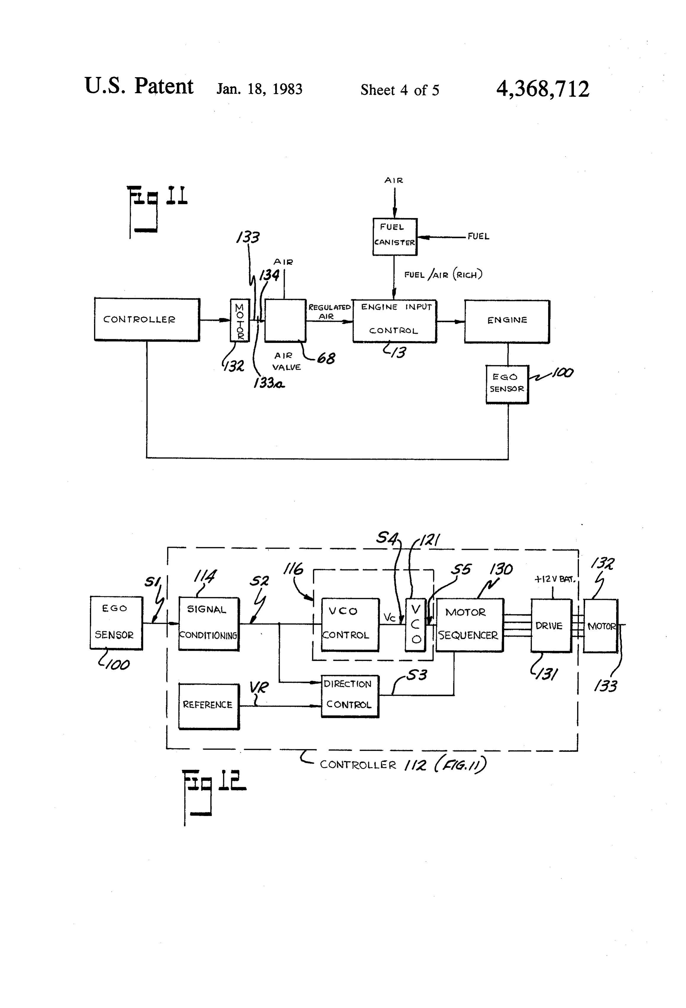
substantial amount of the fabric 77", thus removing 35 In FIGS. 11-13 there is shown the electronic control substantially all of any liquid droplets in the fuel-air that is operable with the present fuel system as previ mixture to maintain maximum efficiency for powering ously disclosed and illustrated in FIGS. 1-10, and the engine. It will be seen that the lower end of the which control is operable to monitor and variably regu fabric material on the side walls of the fuming tank late the fuel-air mixture being delivered to the engine so extend downwardly as at 82, below the lower plate 42' 40 as to maintain the optimum ratio of fuel and air in said of the diffuser 38" and into the pool of liquid fuel which mixture under varying engine load conditions. ordinarily is found therein. Liquid fuel by the "wick As seen in FIGS. 11 and 12, the control uses a sensor ing' action of the fabric is drawn upwardly into the element 100 of conventional design such as the (EGO) fabric covering the side walls and the top wall, wetting Oxygen Sensor No. ES-D9EE-9F472-AB manufac the latter with liquid fuel, and thus aids in fuming the 45 tured by Ford Motor Company hereafter also called fuel-air mixture. A funnel member 83 is provided EGO sensor which is conventionally located in the through plate 42" in general alignment with inlet pipe exhaust gaseous stream of the engine and therein capa 36" so that some fuel-air mixture from pipe 36" passes ble of detecting the presence or absence of free oxygen through lower plate 42". in the exhaust gases. As will be understood in the art, A sight tube 84 may be provided on the exterior of 50 the EGO sensor 100 is operable to emit a voltage signal the fuming tank for indicating the level of liquid fuel that is indicative of the amount of free or uncombined therein. oxygen in the exhaust gases and which signal is hence A housing member 86 is provided over the drain port demonstrative of the fuel-air mixture being delivered to 88, which is connected as by means of a drain line 90 to the engine. For example, if free oxygen is present in the the main fuel tank (not shown), and if the level of liquid 55 exhaust gases it is an indication that too much air was in in chamber 89 gets above the level illustrated, it will the fuel-air mixture input to the engine, and conversely overflow housing 86 and then flow down through open if there is no free oxygen in the exhaust gases it is an ings 92 in enclosure 86 and out the drain 88 to the main indication of either that the fuel-air mixture was at its fuel tank. Expansion chamber 93 may be provided in optimum wherein all oxygen is consumed or that insuf line 90, 60 ficient air was present in the inlet fuel-air mixture which The upper end of the collector member 24" is re would then leave a certain trace of unburned fuel in the duced from the approximately three inch diameter of exhaust gases.
the vertical portion thereof down to approximately one In the present control the operating level or point of and seven-eighths inch diameter where it is connected the EGO sensor is preferably selected so that the "opti to the feed line 28', which is directed to the carburetor. 65 mum' fuel-air mixture tends to be "lean' or approxi As can be seen, an expansion chamber 93 may be pro mately 1 part fuel to 15 parts air by weight to thus, cause vided in line 28", and also a drain 94 may be provided in some free oxygen to be present in the exhaust gases but line 28' and connected by line 96 back to line 90 to the not of such quantity as to generate an intolerable level
Page 12
of nitrous oxide (NO). In the EGO sensor hereinabove to also provide for the adjustment of air to the fuel-air identified this selected operating level usually provides mixture to the engine.
an output voltage signal of above 50 millivolts. The output signal S4 of the control circuit 117 is As seen in FIG. 11, the configuration of the elec connected to the input of a voltage controlled oscillator tronic control disclosed herein is a "closed loop' system 5 121 of conventional design which produces a pulsed wherein a change in the load condition of the engine, as output train or signal as seen at S5 in FIG. 13, the fre for example when the accelerator is depressed to in quency or pulses of which is dependent upon the magni crease engine speed, causes the sensor signal S1 to cor tude of the signal S4. The slower the magnitude of the respondingly change and which signal is then fed to the input signal S4 the greater the frequency of the oscilla input of the control and effective to correspondingly 10 tor output S5 and vice versa.
adjust the fuel-air mixture to the engine. As the fuel-air The pulse output signal S5 and the output signal S3 mixture is adjusted to accommodate the changed load from direction control circuit 118 are connected to the condition of the engine, the corresponding engine re input of a motor drive unit 128, which in its present sponse and resultant exhaust gases indicates the return 15 configuration is a digital linear actuator, Series 92100 as manufactured by the North American Phillips Controls to "optimum condition' and the sensor signal S1 thus Corporation returns to its "optimum signal level' depicted at 1 or 20 of Cheshire, Conn., and which comprises, in FIG. 13.B. as schematically shown in FIG. 12, a motor sequencer As seen in FIGS. 11 and 12, the voltage signal S1 of andAsdrive unit 130 and a linear stepper motor 132. aforementioned, the present sensor system is oper sensor 100 is connected to the input of controller 112, 0 able the schematic configuration of which is illustrated in 2 then tocorrespondingly monitor the exhaust gases of the engine and to adjust the air component of the
The function of the controller is to compare the EGO fuel-air mixture being delivered to the engine so as to maintain the optimum mixture for varying engine load sensor output with a reference signal to determine conditions.
whether corrections in the fuel-air mixture are neces 25 To accomplish this, the stepper motor 132 has a lin sary. It also determines which way to correct the mix early movable shaft 133 as schematically shown in FIG. ture, and the rate at which to correct. If the sensor and 11 which is connected to the movable actuator of one or reference signals are nearly equal, the rate of correction more of the air check valves located at the carburetor is relatively slow whereas if said signals differ to a on greater degree the rate of correction is correspondingly 30 outthe engine. For purposes of this disclosure and with limitation as to the concepts herein, the shaft 133 of relatively fast. the stepper motor 132 is connected by coupling 133a to For this purpose the controller 112 may be of conven the actuator 134 of the air check valve 68, which valve tional design having, in its present configuration, a sig is intended to be movably operable by said stepper nal conditioner circuit 114 which may have one or more motor to variably regulate the quantity of air passing amplification stages connected in circuit with suitable 35 therethrough and into the carburetor 13. dampener and shaper circuits effective to eliminate any signal transients and to amplify the sensor output signal temThe electronic control is connectable to the fuel sys, so that the EGO sensor 100 is located in the exhaust to a signal level of approximately ten times the input gas stream and capable of sensing the same when the signal level. engine is running. The output of said sensor system, i.e. The signal output of the controller 112 tracks the the shaft 133 of the stepping motor 132 is connected to waveform generated by the EGO sensor and is pictori the air check valve 68 as aforesaid. With the engine ally illustrated as signal S2 in FIG. 13. running at idle or slightly thereabove, and with the This signal S2 is then applied to a voltage controlled sensor system responding to the fuel-air mixture so as to oscillator 116 of the controller 112 which, in its present provide a signal to the stepper motor 132 whereby the configuration, comprises a control circuit 117 which 45 air check valve 68 is actuated thereby to a partially open may include one or more suitable differential amplifier condition, permitting air to mix with said fuel-air mix circuits capable of receiving the signal S2 and compar ture the connection between the stepper shaft 133 and ing it with high and low voltage signal limits which may the air check valve 68 is initially adjusted to regulate the be adjustable to produce the output signal waveform as air flowing therethrough until the ratio of fuel to air in depicted at S4 in FIG. 13. 50 said fuel-air mixture is "optimum' at said engine idle Referring to the signal waveform S4 in FIG. 13, it is condition.
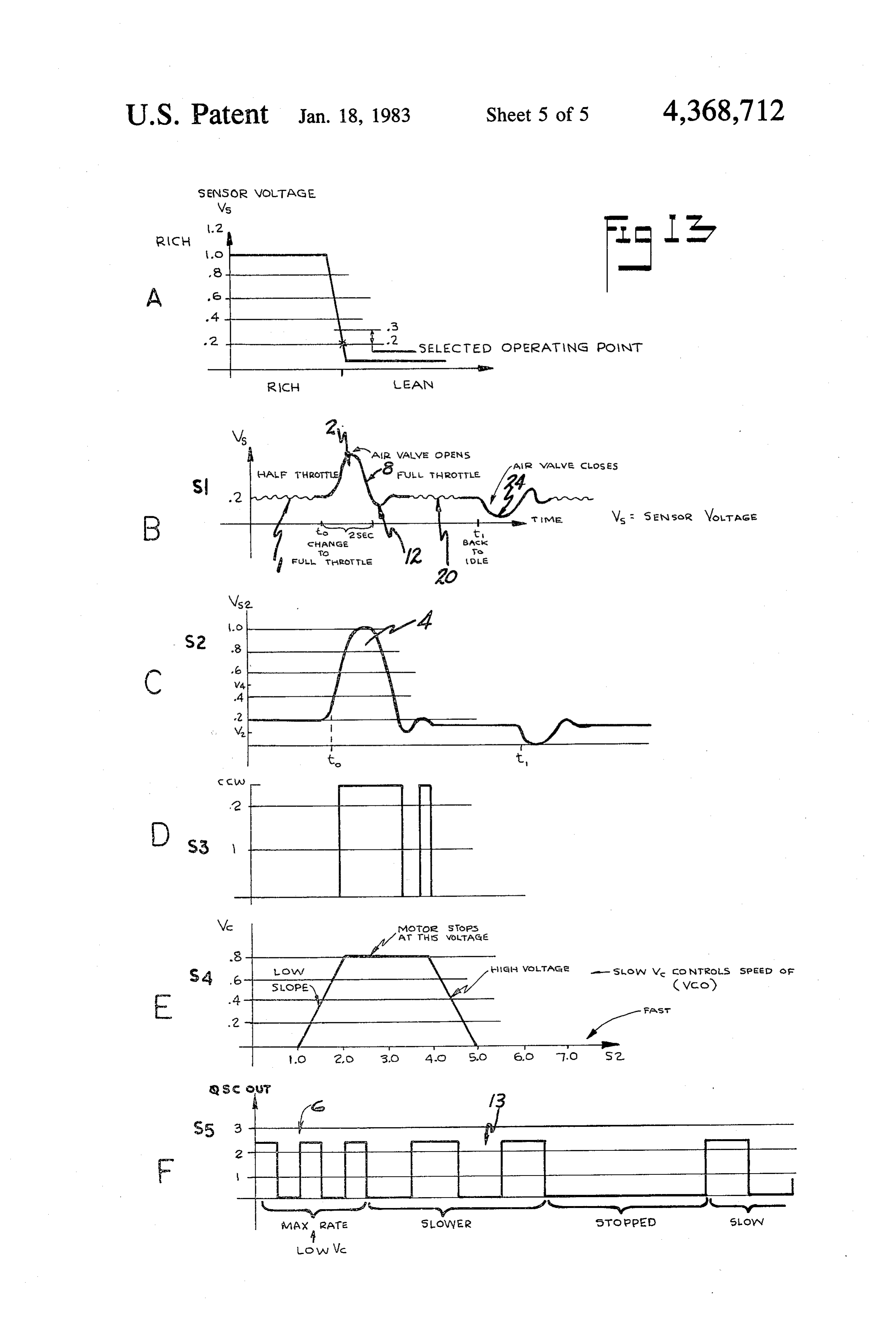
seen to be somewhat trapezoidal in configuration hav With this initial adjustment, it is thereafter anticipated ing the lower voltage limit VL selected as 1.0 volt and that the sensor system will be responsive to any running the upper voltage limit VH as 5.0 volts and a constant condition of the engine to correspondingly variably magnitude of 8.0, volts between the limits of 2.0 volts 55 regulate the air flowing through the air check valve 68 and 4.0 volts. As will be hereinafter discussed in greater for mixing with the fuel-air mixture being thus operable detail, the leading edge of signal S4 is identified as "low to provide an "optimum” fuel-air mixture under all slope' and is intended to enable variable rate adjust conditions of engine operation.
ments to be made to the air of the fuel-air mixture dur Assuming that the vehicle is moving and the engine is ing a relatively lean condition whereas the trailing edge running at some cruising speed, the output signal of the of said signal S4 identified as "high slope' is intended to EGO sensor 100 at said condition is illustrated at 1 in enable variable rate adjustments of said air to the fuel FIG. 13B. If the operator desires greater vehicle speed air mixture during a relatively rich condition. the accelerator pedal or throttle may be depressed to an The signal S2 is also applied to a direction control adjusted position, as for example "fully depressed' circuit 118 of the controller 112 which compares signal 65 whereupon a greater volume of vapor fuel and air is S2 with a fixed voltage reference signal VR to provide immediately drawn into the engine from the fume tank output signal S3 as depicted in FIG. 13 which is uti such that the fuel-air mixture is instantaneously richer, lized, as will be hereinafter described in greater detail, i.e. there is an insufficient amount of air to mix with the
Page 13
increased volume of fuel in said mixture. The signal of the air and fuel, to improve the vaporization process response of the EGO sensor that is indicative of this and thus increase the efficiency of the fuel utilized in the condition is depicted at 2 in FIG. 13B. engine. The invention also provides a novel fuel system This signal condition (2) FIG. 13B, produces the embodying efficient fuming tank mechanism, which is signal response S3 depicted at 4 in FIG. 13C resulting in operable to cause an increase of vaporization of the the signal S4, FIG. 13E being instantaneously greater liquid fuel provided, together with means for more than the high voltage limit VH so that the pulse output completely removing liquid droplets from the fumed train of the voltage controlled occillator is at a maxi fuel, to thus further increase the efficiency of the en mum rate as for example as illustrated at 6 in FIG. 13F. gine.
As a result, the stepper motor is actuated to rapidly O The present fuel system also incorporates therein a open the air valve 68 to a correspondingly "more open' novel electronic control which is operable to monitor position to permit additional air to enter the carburetor the engine combustion and to variably regulate the 13 and mix with the fuel-air mixture prior to its being vapor fuel-air mixture to the engine such that said mix burned. d ture is maintained at its "optimum mixture' for varying This introduction of additional air through valve 68 15 engine load conditions.
thus dilutes said fuel-air mixture bringing it back toward The terms and expressions which have been used are its optimum mixture composition. As this occurs, the used signal response of the EGO sensor also indicates, as there asis no terms of description and not of limitation, and intention in the use of such terms and expres shown at 8 in FIG. 13B, the return of said mixture sions of excluding any equivalents of any of the features toward its optimum composition. shown or described, or portions thereof, and it is recog If the accelerator or throttle is maintained at its "ad justed position', the output signal S4, FIG. 13E pro nized that various modifications are possible within the scope of the invention claimed.
gressively decreases in magnitude until it reaches, as What is claimed is:
illustrated in the present example in FIG. 13E, a magni 1. A fuel system for use with an internal combustion tude of 4.0 volts. At this instant, the stepper motor stops engine
and the air valve 68 is then maintained open in this open ignitablehaving associated fuel delivery means and fuel means for power conversion comprising, a condition.
Because of the inertial response of the engine and the containable source for liquid ignitable fuel, a collector means communicating with said source for collecting instant fuel system, the open condition of valve 68 may fuel fumes or vapor adapted to emanate from said liquid let in too much additional air whereby the fuel-air mix 30 ignitable fuel, means communicable with atmosphere ture becomes "lean' i.e. too much air for the fuel in the and extending into the container source being operable mixture. This "lean' condition is sensed by the EGO sensor and is depicted at 12 in FIG. 13B. This results in to transmit air into said source above the liquid fuel the stepper motor being energized in the opposite direc therein for generating a fumed fuel-air mixture there tion by a pulse train somewhat like that shown at 13 in 35 from, means for transmitting the fumed fuel-air mixture FIG. 13F effective to slowly correspondingly close the from said collector means to the associated fuel delivery air valve 68 whereby less air is permitted to pass there means of the engine for ignition therein, means coacting through. With less additional air, the fuel-air mixture with the means communicable with atmosphere and thus returns to its "optimum composition'. This "hunt responsive to actuation of the engine for insertion of ing' or cyclic actuation of the stepper motor may occur liquid ignitable fuel into said communicable means for one or more times per each operator's adjustment to the intermixing with intake air therein, means coacting with throttle. In the present illustration, as is depicted in said communicable means for diffusing the fuel-air mix FIG. 13B only one such cyclic actuation is shown. ture entering into said containable source above the Once the fuel-air mixture returns to its optimum com liquid fuel therein, and electronic control means coact positional value, this is sensed by the EGO sensor as is 45 ing with said engine and said fuel system being respon illustrated at 20 in FIG. 13B. sive to the operating load conditions of said engine to Thereafter, if a further adjustment to the throttle is correspondingly control the fuel to air ratio of the mix made, as for example the operator releases the throttle ture prior to the transmission of said mixture to said fuel to return the engine to its idle condition, less fuel is delivery means of said engine effective to maintain said drawn into the engine thereby providing a "lean' fuel 50 mixture at its optimum combustible composition. air mixture which is sensed by the EGO sensor as is 2. A fuel system as defined in claim 1 and wherein the depicted at 24 in FIG. 13.B. electronic control means includes at least one sensor This signal is then used to actuate the stepper motor means connectable to and operable to monitor the oper so as to correspondingly adjust the air valve 68 suffi ation of said engine effective to provide a signal to said ciently to reduce the air passing therethrough and thus 55 control and correspondingly adjust the fuel to air ratio return the fuel-air mixture to its optimum composition. of the fuel-air mixture delivered to said engine. Hence, when any adjustment is made by the operator 3. A fuel system as defined in claim 2 and wherein the to the accelerator or throttle, a corresponding adjust sensor means is responsive to the amount of oxygen in ment is automatically made by the present control to the the exhaust stream of the engine and operable to corre air input to the fuel-air mixture so that it is retained in its spondingly adjust the fuel and/or air of the fuel-air "optimum composition' under varying engine loads. mixture.
From the foregoing discussion and accompanying 4. A fuel system as defined in claim 1 and wherein drawings, it will be seen that the invention provides a valve means communicating with the fuel-air mixture is novel fuel system for use with an internal combustion operable to provide air to said mixture, and said valve engine for generating a fumed fuel-air mixture and for 65 means being responsive to said control means to corre supplying such mixture to associated fuel delivery spondingly vary the air to said mixture effective to means of the engine, for ignition therein and which maintain said mixture at its optimum combustible com system includes means for causing improved diffusion position.
Page 14
5. A fuel system as defined in claim 1 and wherein the to maintain said mixture at its optimum combustible . collector means comprises tank means. composition.
6. A fuel system as is defined in claim 5 and wherein 14. A fuel system as is defined in claim 2 and wherein the tank means and the fuel delivery means of the en the control means comprises means for sensing the con gine are adapted to be interconnected by the means for 5 bustion of the fuel-air mixture delivered to said engine transmitting the fumed fuel-air mixture. being responsive thereto to provide a signal representa 7. A fuel system as is defined in claim 6 and wherein tive of said fuel-air mixture, and means operatively the transmitting means comprises conduit means inter connecting said signal to the valve means being opera connected to the tank means and fuel delivery means of 10 ble to correspondingly actuate said valve means and the engine. change the amount of air passing through said valve 8. A fuel system as is defined in claim 7 and wherein means being thus effective to maintain the fuel to air ratio of said mixture at its optimum combustible compo the conduit means connects the input of the fuel deliv sition.
ery means of the engine solely to the tank means.
9. A fuel system as is defined in claim 8 and wherein 15 the15.means
A fuel system as defined in claim 14 and wherein operatively connecting the signal to the valve the engine is operable to provide a vacuum that is effec tive through the conduit means to draw the fumed fuel means comprises motor means. 16. A fuel system as defined in claim 14 and wherein air mixture to the fuel delivery means of the engine.
10. A fuel system as is defined in claim 9 and wherein valvecontrol the means is operable to normally position the the conduit means connects with the input of the fuel to provide a inpreselected means a partially actuated condition effective quantity of air to the fuel-air delivery means in a vapor seal relation effective to seal mixture.
said input from atmosphere. 17. A fuel system as defined in claim 16 and wherein 11. A fuel system as is defined in claim 1 and wherein the valve means is adjustable in response to the signal the means for providing the liquid ignitable fuel to the representative of the fuel-air mixture delivered to said collector means is a containable source. 25 engine to correspondingly modify the amount of air 12. A fuel system as is defined in claim 11 and passing through said valve means being thus effective to wherein the containable source is the fuel tank normally maintain the fuel to air ratio of said mixture at its opti provided with an automotive type vehicle. mum combustible composition. 13. A fuel system as is defined in claim 1 and wherein 18. A fuel system as defined in claim 17 and wherein the control means comprises means for sensing the com 30 motor means operatively interconnected between the bustion of the fuel-air mixture delivered to said engine valve means and the signal is operable in response to the and which is responsive to the combustion of said mix latter to adjust said valve means effective to corre ture to provide a signal representative of said mixture, spondingly modify the amount of air passing there and means responsive to said signal to correspondingly through.
vary the fumed fuel to air ratio of said mixture effective 35 sk k it is
Provenance
- Collection
- Cited prior art
- Original PDF
- patentimages.storage.googleapis.com →
- Filed
- 1980-08-01
- Pages
- 14
- Method
- pdftotext (the PDF's own text layer) + pdftoppm 300dpi page scans
- Source
- Google Patents bibliographic record
- Granted
- 1983-01-18
- Inventors
- Kenneth A. Jackson; George I. Arndt; James L. Maynard; V G A S Inc
- Transcribed from
- patentimages.storage.googleapis.com →