patent · US4750453
Internal combustion engine
14 June 1988
Page 1 — bibliographic record
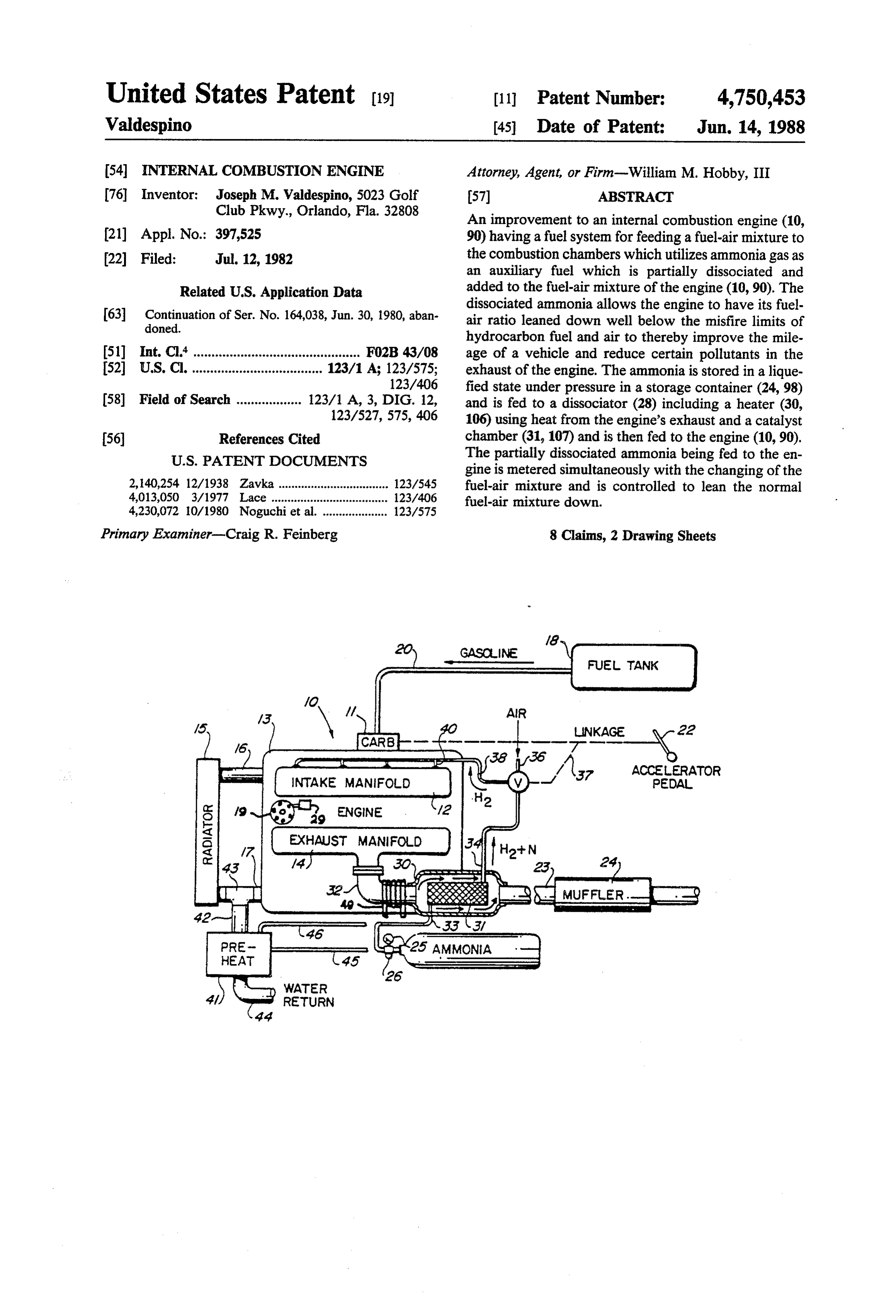
United States Patent (19) 11 Patent Number: 4,750,453 Valdespino 45 Date of Patent: Jun. 14, 1988 54 INTERNAL COMBUSTION ENGINE Attorney, Agent, or Firm-William M. Hobby, III 76 Inventor: Joseph M. Waldespino, 5023 Golf 57 ABSTRACT Club Pkwy., Orlando, Fla. 32808 An improvement to an internal combustion engine (10, (21) Appl. No.: 397,525 90) having a fuel system for feeding a fuel-air mixture to 22 Filed: Jul. 12, 1982 the combustion chambers which utilizes ammonia gas as an auxiliary fuel which is partially dissociated and
Related U.S. Application Data added to the fuel-air mixture of the engine (10,90). The 63 Continuation of Ser. No. 164,038, Jun. 30, 1980, aban dissociated ammonia allows the engine to have its fuel doned. air ratio leaned down well below the misfire limits of hydrocarbon fuel and air to thereby improve the mile 51) Int. Cl." .............................................. FO2B 43/08 age of a vehicle and reduce certain pollutants in the 52 U.S. C. .................................... 123/1 A; 123/575; exhaust of the engine. The ammonia is stored in a lique 123/406 fied state under pressure in a storage container (24, 98) 58) Field of Search .................. 123/1 A, 3, DIG. 12, and is fed to a dissociator (28) including a heater (30, 123/527, 575, 406 106) using heat from the engine's exhaust and a catalyst (56) References Cited chamber (31, 107) and is then fed to the engine (10,90).
gine is metered simultaneously with the changing of the 2,140,254 12/1938 Zavka .................................. 123/545 fuel-air mixture and is controlled to lean the normal 4,013,050 3/1977 Lace ...... -- - - - 123/406 fuel-air mixture down.
4,230,072 10/1980 Noguchi et al. .. 123/575
Primary Examiner-Craig R. Feinberg 8 Claims, 2 Drawing Sheets
FUEL ANK
ACCEERATOR
PEDAL
WATER
RETURN
Page 2
Drawing sheet — no readable text.
Page 3
Drawing sheet — no readable text.
Page 4
control the feed of the hydrogen to the engine so that
INTERNAL COMBUSTON ENGINE the conventionally fueled engine can be run very lean, well below where the engine would normally misfire as
This invention is a continuation of my invention in the engine approaches the flammability limit of the fuel. my co-pending U.S. patent application for an Internal 5 The normal flammability limit for hydrogen fuel-air Combustion Engine, Ser. No. 164,038, filed on June 30, mixtures occurs with a relatively high NOx formation 1980 now abandoned. rate and thereby imposes severe limitations on the lean BACKGROUND OF THE INVENTION limit operation for the fuel. Since hydrogen exhibits a 1. Field of the Invention flammability limit well below that of conventional hy 10 drocarbon fuels, it is possible to reduce the NO simply
The present invention relates to internal combustion by using the hydrogen to change the fuel-air mixture to engines and especially to improvements in internal com a much leaner mixture than would normally be allowed. bustion engines having an auxiliary ammonia gas feed The metering gas through a dissociation system into the lenceextension ratios of the misfire limit to very lean equiva with hydrogen fuel also yields significant combustion chambers along with the normal hydrocar 15 increases in the thermodynamic bon fuel-air mixture of the engine while leaning the bustion process, thereby allowingefficiency a of the com substantial increase engine below its normal operating fuel-air mixture. in the mileage obtained on a conventional internal com 2. Description of the Prior Art bustion fueled engine vehicle. In the past, a variety of internal combustion engines have been provided and typically these engines have a 20 fuelTheordifficulties in using hydrogen either as the sole system for feeding a hydrocarbon fuel, such as gasoline combustion engine resultswith in combination from a conventional internal the hydrogen being a mixed with air into the combustion chamber for running ubiquitous and very flammable gas, the engine. Such engines typically also have an electri creases the hazards of operating the soengine that storage in and in the cal system which includes a generator or an alternator general inefficiency in generating the hydrogren such as which may be connected through an electrical regulat through electrolysis on the vehicle.
ing circuit for charging a storage battery and for operat ing the electrical components of the engine of the vehi The present invention is directed toward the use of an cle. Internal combustion engines sometimes have hy hydrocarbonammonia gas used in combination with a conventional drocarbon fuels mixed with air in a carburetor where fuel-air mixture to increase the efficiency of the engine the mixture is distributed into the combustion chambers 30 Ammonia has been and to reduce pollution in the engine. of the engine. It is also typical to feed the air to the mentioned as a constituent of vari combustion chambers using a fuel injection system for ous types of fuels in the past, both for internal combus injecting fuel directly into the combustion chambers. tion engines and for jet propulsion. One such fuel is a The present invention can be adapted to operate with liquid mixture of ammonious nitrate in liquid ammonia either a carburetor or fuel injection system. 35 which is a self-sustaining fuel combination requiring no A variety of hydrogen fueled engines have been sug addition of an oxident such as air. Ammonia is also used gested in the past, including those using combinations of to manufacture hydrozene, a well known rocket fuel, hydrogen and oxygen, which in some cases are gener and while ammonia does not support combustion, it will ated in an electrolytic cell having an electrolyte includ burn when mixed with oxygen in air to give a variety of ing solutions of salts, acids or bases in water. The elec products, principally nitrogen and water. Mixtures of trolytic cell breaks the water down between hydrogen nitrous oxide and ammonia in a rate of 3 to 2 will deto and oxygen through electrolysis and the hydrogen or nate with some violence yielding nitrogen and water. the hydrogen and oxygen in combination can then be One prior U.S. Patent showing the use of ammonia as used to run the engine. The advantage of the hydrogen constituent in fuel for internal combustion engines can and oxygen as fuel is that it is an efficient fuel which 45 be seen in the Drouilly U.S. Pat. No. 2,559,605, for a generates no pollution in that the combustion forms fuel mixture for internal combustion engines. In this water in very minute quantities. Such engines, however, patent, ammonia gas is fed from one storage cylinder have not been brought into general use because of the into a pressure reducing chamber and a second bottle inefficiency in the generation of hydrogen and oxygen containing an auxiliary gas, such as ethanized illuminat through electrolysis which takes far more power than 50 ing gas, is fed into a second expansion chamber and the can be generated from the hydrogen and oxygen used as two gases are then fed into a mixing chamber, and from a fuel, even in high efficiency engines. the mixing chamber into a carburetor. This patent also It has also been suggested to use small amounts of discusses the use of carbomonoxide, methyl ether, ethyl hydrogen added to the hydrocarbon fuel-air mixture to ether, methyl amine and ethyl amine in combination increase the efficiency or reduce the pollution of the 55 with ammonia. In the U.S. patent to Meyer, U.S. Pat. internal combustion engine. One prior patent, U.S. Pat. No. 1,671,158, a fuel for use in internal combustion No. 3,906,913, discusses in detail the advantages of the engines consists of a mixture of hydrocarbon distillates use of small amounts of hydrogen with the hydrocarbon with ether and a highly volatile basic material, which fuel-air mixture of a vehicle and points out that the may be ammonia. The mixture can then be used in inter advantages of reduced pollution and increased mileage 60 nal combustion engines according to the patent. The result from running the engine much leaner than can U.S. patent to Brooks, U.S. Pat. No. 1,748,507, shows a otherwise be accomplished because the misfire limit for process of reducing stable hydrocarbon oils in which hydrocarbon fuels can be well exceeded. The carbon ammonia or certain alkaline compounds are mixed with monoxide and NOx (oxides of nitrogen) emissions have light hydrocarbon oils to prevent discoloration and been found to decrease as the fuel-air ratio is made 65 sedimentation. In two of these U.S. patents, ammonia is leaner and if the fuel-air ratio can be made sufficiently used in small amounts in a fuel mixture, which may then lean, it can be made substantially free of CO and NO. be used as a fuel in an internal combustion engine; while This patent shows a hydrogen generator and means to in the Drouilly patent, expanded ammonia gas is mixed
Page 5
with another gas to form a gaseous fuel mixture for internal combustion engine with the fuel-air mixture running an internal combustion engine. charge. A feed control valve meters the ammonia for Other prior U.S. patents utilizing ammonia as a fuel varying the rate of feed of the ammonia to the combus include U.S. Pat. No. 3,150,645 which uses a method of tion chamber responsive to varying operating condi operating a compression ignition engine using ammonia 5 tions of the internal combustion engine while a catalyst as the primary fuel; U.S. Pat. No. 1,384,946 for a com and waste engine heat are coupled between the storage posite motor fuel which uses reagents admixed with the tank and the engine. The ammonia gas being fed to the fuel to neutralize or destroy the corrosive products of engine combustion chambers allows the internal com explosive combustion in the engine cylinders, which bustion engine fuel-air mixture to be leaned to a point include among other reagents, ammonia. In U.S. Pat. 10 below the operating limits of the engine using only No. 4,223,642, a small amount of ammonia gas is ob hydrocarbon fuel.
tained from ammonia bicarbonate or ammonia carbon BRIEF DESCRIPTION OF THE DRAWINGS ate for use in the internal combustion engine. In U.S.
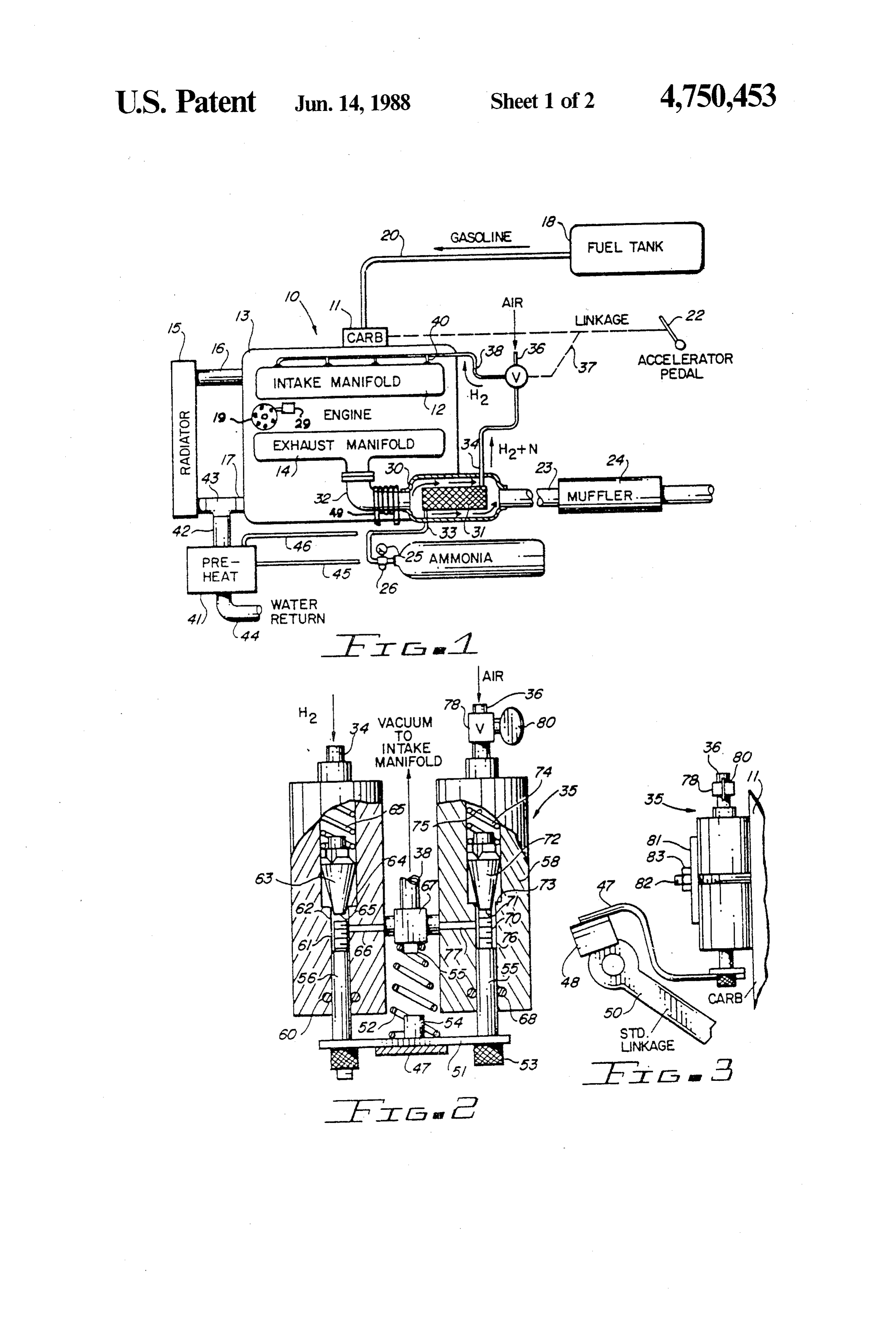
Pat. No. 2,140,254 to Zavka, an internal combustion Other objects, features and advantages of the present engine is operated on ammonia as a fuel by dissociating 15 invention will be apparent from the written description a small portion of the ammonia into hydrogen and nitro and the drawings in which:
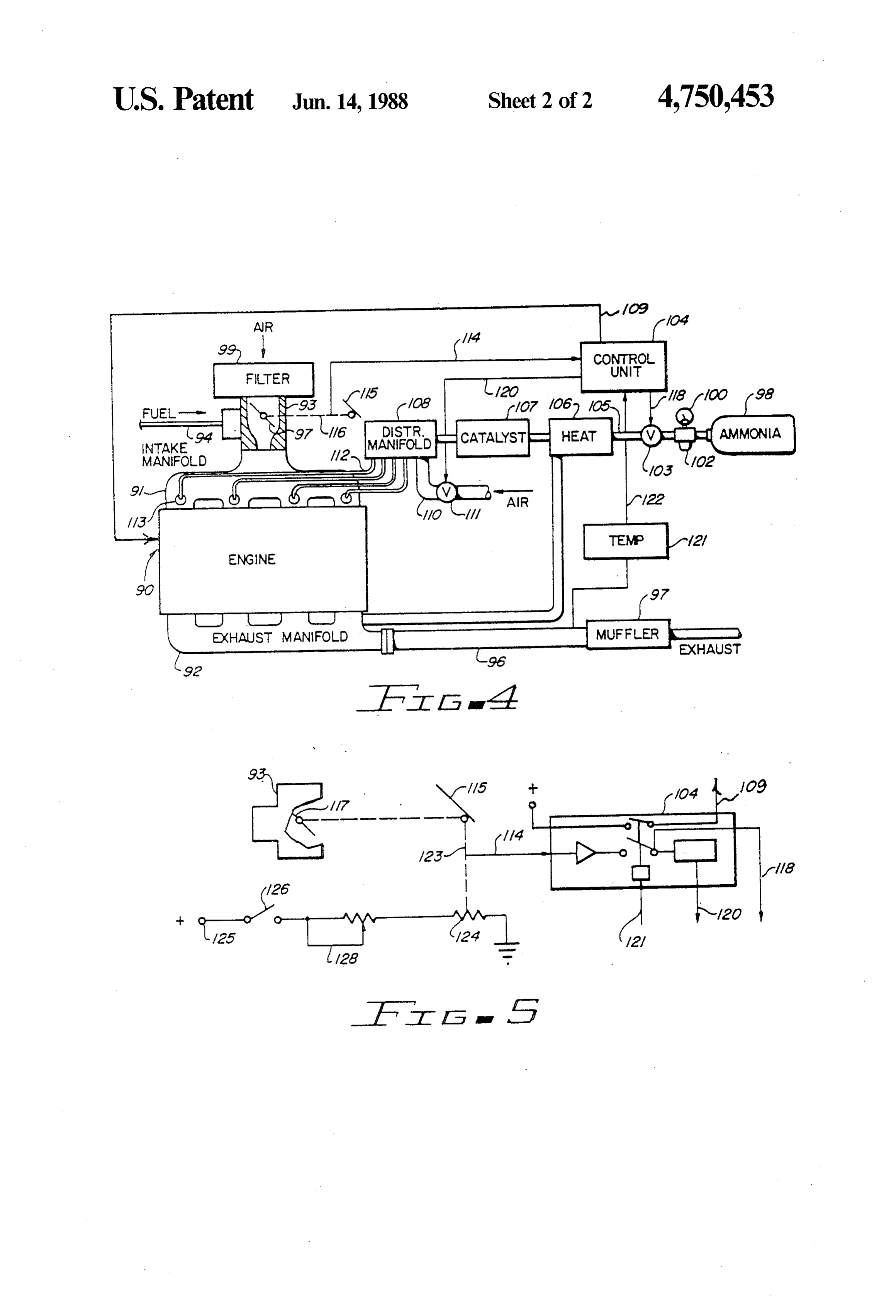
gen, utilizing exhaust heat, and then adding the dissoci FIG. 1 is a diagrammatic view of an internal combus ated gas back into the ammonia gas to run the engine. tion engine fuel system in accordance with the present The hydrogen apparently extends the flammability lim invention;
its of the ammonia so that it can be used as a fuel. Am 20 FIG. 2 is a cutaway side elevation of a gas metering monia, however, has only about half the btu value per valve used in the embodiment of FIG. 1; pound as gasoline, and therefore, by itself is not consid FIG. 3 is a side elevation of the throttle connection ered an efficient fuel. In addition, its narrow flammabil for the gas metering valve of FIG. 2; ity range makes it difficult to use as a fuel. FIG. 4 is a diagrammatical view of a second embodi Other prior art patents can be seen in U.S. Pat. Nos. 25 ment of the invention; and 4,036,180 and 4,230,072, both to Noguchi, et al., for fuel FIG. 5 is a circuit diagram for the electronic control reforming systems for internal combustion engines re of the valve shown in FIG. 4.
forming methanol; and in U.S. Pat. No. 1,899,869 for a DESCRIPTION OF THE PREFERRED gas engine; U.S. Pat. No. 4,054,423 for a variable pres EMBODIMENTS sure fuel generator and method; and in U.S. Pat. Nos. 30 3,915,125, 4,121,542 and 3,963,000. Referring to FIGS. 1 through 3 of the drawings, an The advantage in using ammonia in the present inven internal combustion engine (10) is illustrated with a tion is that ammonia is useful as a convenient means for carburetor (11) feeding into an intake manifold con ...transporting small volumes of hydrogen since the gas nected to the engine block (13), which also has an ex obtained by decomposition contain 75% by volume of 35 haust manifold (14) connected thereto and a radiator hydrogen and 25% by volume of nitrogen. The ammo (15) connected to the engine block (13) by water hoses nia is easily liquefied either by cooling to below its (16, 17). The engine (10) is a standard internal combus normal boiling point of -33.42 C. or by compression tion engine using refined hydrocarbon fuels fed from a ... and can be stored in a liquid state in small compression fuel tank (18) through a gas line (20) to the carburetor cylinders. Ammonia can be thermally dissociated in the (11), and connected by throttle linkage (21) to accelera ... presence of certain catalysts to give nitrogen and hy torpedal (22) located in a vehicle. The exhaust from the ". ... drogen and dissociation can also be affected by photo exhaust manifold (14) is fed through the tailpipe (23) ... chemical means or by passing an electrical discharge through a muffler (24) into the atmosphere, and in re through the gas. Ammonia can be obtained a number of cent engines might include a catalytic converter as part ways, but is normally prepared synthetically by a modi 45 of a pollution control package. The engine illustrated is fication of the Haber process using pressures between a standard internal combustion engine of the type used 200 and 1,000 atmospheres and temperatures between in vehicles, but the present invention can be easily 400" and 500 C. along with a variety of catalysts. The adapted to an engine having fuel injection rather than a present invention advantageously can be adapted as an carburetor or to a diesel engine burning oil rather than addon to existing hydrocarbon fueled internal combus 50 gasoline.
tion engines, as well as designed for new vehicles and A tank of anhidrous ammonia (24) is attached to the allows a substantial increase in the mileage obtained engine (10) has a pressure gauge (25) and an ammonia from the hydrocarbon fuels and a reduction of at least safety release valve (26) attached to the ammonia tank certain pollutants in the exhaust of a vehicle and since (24). The safety release valve is a spring loaded valve the dissociated ammonia is metered in accordance with 55 which will open momentarily when the pressure ex the requirements of the engine and the leaning of the ceeds a predetermined pressure, such as 250 psi. Ammo engine can be similarly controlled, the efficiency can be nia is stored in the ammonia storage tank (24) in a liquid easily optimized for any particular internal combustion state, but is fed in a gaseous or liquid state out a line (27) engine. and in a gaseous state into an ammonia dissociator (28)
SUMMARY OF THE INVENTION
having an enlarged cylinder (30) having a spaced inner cylindrical chamber (31) mounted therein so that ex
An improvement in internal combustion engines is haust gas coming out of the header (32) passes through provided in an internal combustion engine having a the enlarged cylinder (30) into the tailpipe (23), around conventional hydrocarbon fuel-air mixture for produc the inner cylinder (31). The inner chamber (31) is filled ing the internal combustion within the combustion 65 with one or more catalysts from a group including iron, chambers. An ammonia storage tank is used for storing nickel, osmium, zinc and uranium. Typically, the cata of ammonia in proximity to the internal combustion lyst might be iron and nickel, which may be in the form engine for feeding ammonia from the storage tank to the of steel wool, or the like, so that the gas entering the

Page 6
chamber (31) passes therethrough while being heated place by members (54, 55). The pressing on the acceler by the considerable heat of the engine exhaust, so as to ator pedal pushes the throttle linkage (50) and bracket utilize the waste exhaust heat for dissociation. In the (58) to push the connecting bracket (47), which may be presence of the catalyst, the dissociation of ammonia welded or bolted to the bracket (58) to push the plate begins as low as 300° C. and is nearly complete at (51) against spring (52), driving a pair of sliding rods 500-600 C. The ammonia gas enters the dissociator (55,56). Rod (56) rides in a gas feed housing (57) fed by (28) at the input (33) at one end of the chamber (31) line (34), as seen in FIG. 1, while sliding rod (55) slides while passing through the catalyst. The catalyst baffles in a housing (58) fed by the air input line (36). Sliding the gas and assists in the rapid heating of the gas passing rod (56) may have an O-ring seal (60) and a threaded therethrough. The gas in line (34) is substantially disso 10 adjusting rod (61) threaded into the shaft (56). The ciated ammonia, 3 parts hydrogen and 1 part nitrogen, adjusting rod (61) slides in a chamber (62) and engages but would retain at least traces of ammonia with the a truncated cone valve element (63), which operates in disassociated gas. The dissociation of ammonia appears connection with the valve seat (64). The valve element to be analogous to the reverse of the Haber process, (63) is spring loaded by a spring (65), so that raising or which uses high pressure so that it is believed that the 15 lowering the plate (51) raises or lowers the shaft (56), negative pressure generated by the intake manifold and threaded member (61) to push against the bottom vacuum enhances the dissociation of the ammonia. En (69) of the valve element (63) to drive the valve element gine (10) has an ignition system including a distributor (63) agsinst the spring (65) thereby opening the valve in (19) which is a solenoid (29) connected thereto to ad proportion to the movement of the throttle linkage to vance the spark whenever the solenoid (29) is actuated 20 allow gas to pass around the valve seat (64) through a and to return the spark to normal when the solenoid passageway (66) into a T-connection (67) and out line (29) is switched off. The same switch may initially turn (38). Similarly, lifting of the plate (51) lifts the shaft (55) on the ammonia and advance the spark and the switch which has an O-ring seal (68) and a threaded adjusting can be thermostatically activated as shown in connec member (70) which is then threaded into the shaft (55) tion with FIGS. 4 and 5. 25 and will push against the base (71) of a truncated cone The gases in line (34) are fed to valve (35), the opera valve element (72) operating in conjunction with valve tion which is shown more clearly in FIG. 2. The valve seat (73). The valve element (72) is spring biased by (35) has an air input line (36) and is actuated from a spring (74) in a chamber (75). The shaft (70) passes linkage (37) connected to the throttle linkage (21) through a smaller chamber (76) opening to a passage which is operated by the accelerator pedal (22). The gas 30 way (77) into the T-connection (67). This side of the from line (34) and the air from the air input line (36) are valve also has an adjusting valve (78), adjusted with a fed through a line (38) and through individual lines (40) handle (80) to provide a fixed adjustment for the flow of into individual inputs to the intake manifold (12) so as to air from the pipe (36).
distribute the air mixed with the dissociated ammonia In operation, the accelerator pedal (22), of FIG. 1, is and any ammonia evenly into each cylinder. The air is 35 operated in a normal manner, but drives the throttle fed through line (36) in a controlled ratio and is an easy linkage and thereby the bracket (47) attached to throttle method of leaning down the normal air to hydrocarbon plate (48) to raise and lower plate (51) to vary the input fuel mixture of the carburetor (11). That is, the more air of hydrogen, nitrogen and any residual ammonia from fed into line (36) and into the intake manifold, the leaner the line (34) and the air from the air line (36) into the the intake mixture. 40 line (38), which is coupled into the individual intake The amount of air being fed to the combustion cham manifold inlets. The valve (35) is supported by a bracket bers, as well as the amount of dissociated ammonia is (81) and a bolt (82) and nut (83) to the carburetor (11). actuated through a connection to the throttle linkage It should be clear at this point that an ammonia, hy (21). The hydrogen input, as well as the amount of drocarbon fuel and air system has been provided for leaning, is varied in accordance with the operation of 45 internal combustion engines. It should also be clear that the throttle to give a more efficient mixture of hydro the system can be adapted for fuel injection systems, gen, hydrocarbon fuel and air. An alternate ammonia and that the dissociator (28) and the catalyst do not preheater (41) is illustrated connected to a water line have to be in the combined unit as illustrated in FIG. 1, (44) and back into the cooling system of the engine (10). but can be separate units if desired. It should also be A second alterne preheater (49) coils the tube (33) 50 clear that a significant increase in the mileage obtained around the exhaust manifold (32) prior to feeding the in a standard gasoline engine is believed to be due to the tube (33) into the catalyst chamber (31). An ammonic leaning of the engine below the normal misfire limits by inlet line (45) can be connected to the line (27), pass the use of dissociated hydrogen, and that the leaned through a coiled pipe or heat exchanger located in the down engine is believed to provide significant improve preheater (41) where it is connected to the line (33) 55 ment in the reduction of at least certain of the pollutants feeding into the dissociator (28). The preheater can generated by the conventional internal combustion en remove the chill from the rapidly expanding ammonia gine, even with the addition of added nitrogen to the gas and thereby reduce the total amount of heat that engine from the dissociated ammonia. However, ammo must be provided in the dissociator (28). A preheater nia that has not dissociated, as well as added nitrogen, can also be made in other ways, such as wrapping the are believed to increase the benefits obtained in combus ammonia line around the tailpipe, without departing tion.
from the scope of the invention. Turning now to FIGS. 4 and 5, a third embodiment of Turning to FIG. 2, the valve (35) is illustrated in the present invention is illustrated having an internal more detail and has a throttle linkage connection mem combustion engine (90) with an intake manifold (91), an ber (47) connected to a throttle linkage member (48), exhaust manifold (92) and a standard carburetor (93), attached to a standard linkage (50). The throttle linkage having a liquid hydrocarbon fuel line (94) feeding into a (47) abuts against a plate (51) which is spring loaded by fuel bowl (95), forming part of the carburetor (93). Air spring (52) against stop nuts (53). Spring (52) is held in is fed through an air filter (95) into the carburetor (93)
Page 7
and into the intake manifold (91) and thus into the com being fed to the unit until sufficient heat is available to bustion chambers of the internal combustion engine dissociate a portion of the ammonia. A momentary (90). While exhaust gases from the combustion cham delay circuit can momentarily delay the signal in the bers is fed through a tailpipe (96), a muffler (97) and into line (120) to the valve (111) to assure that the air and the atmosphere. An ammonia storage tank (98) stores ammonia gas will reach the distribution manifold (108) ammonia in a liquefied state and has a pressure gauge at the same time, so as not to momentarily lean the (100) and ammonia safety release valve (101) which is engine (90) down, prior to dissociated ammonia being adapted to momentarily open when the pressure ex fed to the engine.
ceeds the predetermined set pressure and to close after A simplified electrical control embodiment of the a short opening. The ammonia as a liquid or gas is fed 10 invention has been illustrated in connection with FIGS. from the cylinder (98) containing liquid ammonia 4 and 5, but it should be clear that the next generation through a line (102) through an electronically con control unit would typically include a microprocessor, trolled fuel valve (103) which varies in accordance with receiving signals not only from the throttle, but may the voltage applied thereto by a central electronic con include an exhaust sensor which changes its electrical trol (104). Ammonia passing through the valve (103) 15 conductivity corresponding to the concentration of passes through a line (105) into the heating unit (106) certain exhaust gases, oxygen or hydrogen over the capturing heat from the exhaust of the engine. The sensor. In addition, exhaust gas control systems such as heating unit is located as close to the combustion cylin are commonly used on airplanes may be adapted for use ders as possible, and may be incorporated into the ex in the control unit, along with sensors indicating engine haust header. Ammonia gas also passes through a cata 20 speed and intake manifold pressure, which input signals lyst (107) which normally would be combined with the can produce an optimum control of the feeding of disso heating unit (106) as illustrated in connection with FIG. ciated ammonia and air to the engine (90) even if the 1. Ammonia gas from the catalyst (107) is fed into a desired feed in non linear. It should be clear that the distribution manifold (108) which is connected to an air feeding of air for leaning the engine (90) is easily accom inlet (110) through a second electronic controlled valve 25 plished for add-on units for adding onto existing internal (111) which meters the air being fed to the distribution combustion engines (90), but that the engine can also be manifold (108). The combination of air and at least leaned through specially designed carburetors without partially dissociated ammonia is fed through a plurality departing from the spirit and scope of the invention. A of gas lines (112) to individual manifold inlets (113) of custom designed carburetor or fuel injection unit might the intake manifold (91). Thus, in this embodiment, the 30 also include the control of the feed of the ammonia with control unit (104) varies the valves (103, 111) to vary the fuel-air mixture leaned in a different manner without the amount of dissociated ammonia gas and air fed to departing from the spirit and scope of the invention. the intake manifold, thereby varying the input of gas as Similarly, the control of the unit of a fuel injection well as leaning the engine in accordance with the con engine can be operated in conjunction with the control trol unit. 35 of the injectors. It should also be clear that the engine The control unit has an electrical conductor (114) can be switched over entirely to dissociated ammonia. which is connected to the accelerator pedal (115) which Accordingly, the present invention is not to be con is connected to the throttle linkage (116) and to the strued as limited to the forms shown herein, which are throttle (117). Conductor (114) then feeds a signal that to be considered illustrative rather than restrictive. can vary the output voltage or signal through line (118) 40 What is claimed is:
to the valve (103) and through the line (120) to the valve 1. An improvement in internal combustion engines (111) to open the normally closed valves in proportion characterized by:
to the movement of the throttle. A temperature sensor an internal combustion engine having fuel feed means (121) can be inserted in the exhaust system, such as in for feeding a hydrocarbon fuel-air mixture to at the exhaust header, to produce a signal through the line 45 least one combustion chamber, said engine having (122) to the control unit (104). A conductor (109) ad an exhaust system for feeding exhaust gases from vances the spark of the engine whenever the ammonia is said internal combustion engine, an intake mani being fed to the engine and this may be done by actuat fold, a throttle and throttle linkage and a cooling ing a solenoid to rotate the distributor a set number of system to cool said engine; degrees. When the relay in the control unit (104) is 50 ammonia storage means for storing ammonia in prox opened as shown in FIG. 5, the solenoid is released and imity to said internal combustion engine; the unit returns to normal by retarding the spark. ammonia feed means for feeding ammonia from said The control unit (104) can be more clearly under ammonia storage means to the internal combustion stood in connection with FIG. 5, in which the accelera engine combustion chamber with said fuel-air mix torpedal (115) is connected through a linkage (123) to 55 ture charge;
the movable contact of a poteniometer (124) which is means coupled to said ammonia feed means between connected from an electrical terminal (125) through the said ammonia storage means and said internal com ignition switch (126) through the potentiometer (124) to bustion engine for dissociating said ammonia into a ground (127) to thereby vary the voltage in the line hydrogen and nitrogen and feeding said gas to said (114) to the control unit (104). A variable resistance 60 engine with the hydrocarbon fuel-air mixture, (128) can be used to determine the minimum value of whereby ammonia is fed into a combustion cham the signal of the moving contact of the potentiometer ber substantially dissociated; (124). The control unit (104) includes a standard ampli feed control valve means connected to said ammonia fier for amplifying the signal from the line (114) as well feed means for varying the rate of feed of said as a relay or solenoid switch actuated by the thermal 65 ammonia to said combustion chamber responsive sensor (122). The thermal switch disables the control to operating conditions of said internal combustion unit (104) until a sufficient temperature is reached in the engine, said feed control valve means being opera exhaust manifold. This prevents ammonia and air from tively connected to the throttle linkage of said
Page 8
internal combustion engine and being actuated said internal combustion engine to heat ammonia pass responsive to the movement of said throttle and ing therethrough above 300° C.
said feed control valve means including a throttle 4. An internal combustion engine in accordance with bracket which actuates a pair of valve elements to 5 claimtem 1, including means to advance said ignition sys spark upon the hydrocarbon air fuel being leaned increase the flow of gas and air as the as the throttle by said means to lean the hydrocarbon fuel-air mixture is moved to increase the feed of hydrocarbon fuel and to retard the ignition system spark upon said hydro and air to said internal combustion engine; carbon air-fuel being enriched by said means to lean the means to lean the hydrocarbon fuel-air mixture of hydrocarbon fuel-air mixture.
said internal combustion engine below the normal 10 5. An internal combustion engine in accordance with hydrocarbon fuel-air operating range when ammo claim 1, in which said means for leaning said internal nia is being dissociated and fed from said ammonia combustion engine includes an air feed means for feed storage means by said ammonia feed means to said ing6.additionalAn air into said intake system of said engine.
internal combustion engine in accordance with internal combustion engine; and 15 claim 5, in which said means to lean the fuel-air mixture means to switch said internal combustion engine back to said engine includes feeding air mixed with dissoci to a normal hydrocarbon fuel-air mixture when ated ammonia gas into the intake manifold of said inter said ammonia dissociation means has insufficient nal combustion engine.
heat to dissociate the ammonia, and an ammonia 7. An internal combustion engine in accordance with preheater connected to said internal combustion claim 1, in which dissociation means has heating means engine cooling system to preheat said ammonia having a chamber mounted for the engine exhaust gases prior to heating said ammonia in said dissociation ammoniato pass therearound and having a connection for feeding 12S in one end portion of said chamber and disso ciated 2. An internal combustion engine in accordance with 25 chamber havingout the other end portion of said chamber, said a catalyst therein.
claim 1, in which said catalyst includes nickel. 8. An internal combustion engine in accordance with 3. An internal combustion engine in accordance with claim 7, in which said catalyst includes iron. claim 1, in which the dissociating means is coupled to is a 38
Provenance
- Collection
- Cited prior art
- Original PDF
- patentimages.storage.googleapis.com →
- Filed
- 1982-07-12
- Pages
- 8
- Method
- pdftotext (the PDF's own text layer) + pdftoppm 300dpi page scans
- Source
- Google Patents bibliographic record
- Granted
- 1988-06-14
- Inventors
- Joseph M. Valdespino
- Transcribed from
- patentimages.storage.googleapis.com →