patent · US4054423
Variable pressure fuel generator and method
18 October 1977
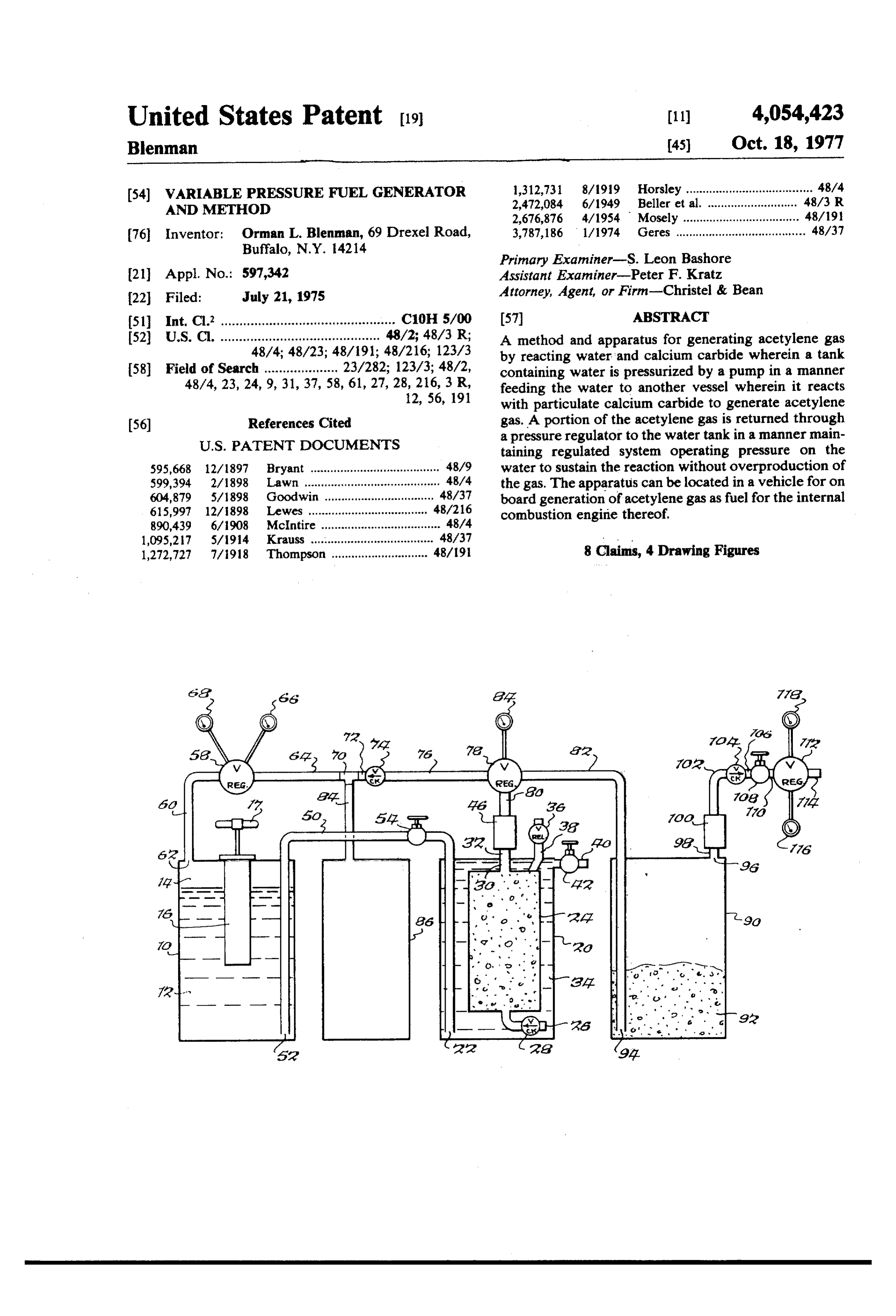
Page 1 — bibliographic record
United States Patent (19) (11) 4,054,423 Blenman 45) Oct. 18, 1977 (54) VARIABLE PRESSURE FUEL GENERATOR 1,312,731 8/1919 Horsley ...................................... 48/4 AND METHOD 2,472,084 6/1949 Beller et al. ..... ... 48A3 R 2,676,876 4/1954 Mosely ......... ... 48/19 76 Inventor: Orman L. Blenman, 69 Drexel Road, 3,787,186 1/1974 Geres ....................................... 48/37
Primary Examiner-S. Leon Bashore (21) Appl. No.: 597,342 Assistant Examiner-Peter F. Kratz 22 Filed: July 21, 1975 Attorney, Agent, or Firm-Christel & Bean 51) Int, Cl. ............................................... C10H 5/00 (57) ABSTRACT 52 U.S. Cl. "48/448/23: 48/191, i.i. A method and apparatus for generating acetylene gas 58 Field of h A; 48/23; 23 282. 123 3. 48/2 by reacting water and calcium carbide wherein a tank
containing water is pressurized by a pump in a manner feeding the water to another vessel wherein it reacts wW with particulate calcium carbide to generate acetylene (56) References Cited gas. A portion of the acetylene gas is returned through
taining regulated system operating pressure on the 595,668 12/1897 Bryant ....................................... 48/9 water to sustain the reaction without overproduction of
the gas. The apparatus can be located in a vehicle for on 615,997 12/1898 Lewes ... . . 48/216 as Erin?;" gas as fuel for the internal 890,439 6/1908 McIntire ... 48/4 1,095,217 5/1914 Krauss .......... ... 48/37 . .
1,272,727 7/1918 Thompson ............................. 48/19 8 Claims, 4 Drawing Figures
Page 2
Drawing sheet — no readable text.
Page 3
Drawing sheet — no readable text.
Page 4
supply acetylene gas fuel to the internal combustion
VARIABLE PRESSURE FUEL GENERATOR AND engine thereof;
METHOD FIG. 3 is a diagrammatic view of an arrangment ac cording to the present invention for supplying acetylene
BACKGROUND OF THE INVENTION gas to the carburetor of an internal combustion engine; This invention relates to the art of chemical gas gen and , eration, and more particularly to a new and improved FIG. 4 is a diagrammatic view showing the apparatus method and apparatus for generating acetylene gas. of the present invention housed in a cylinder to supply One area of use of the present invention is in generat acetylene gas for welding.
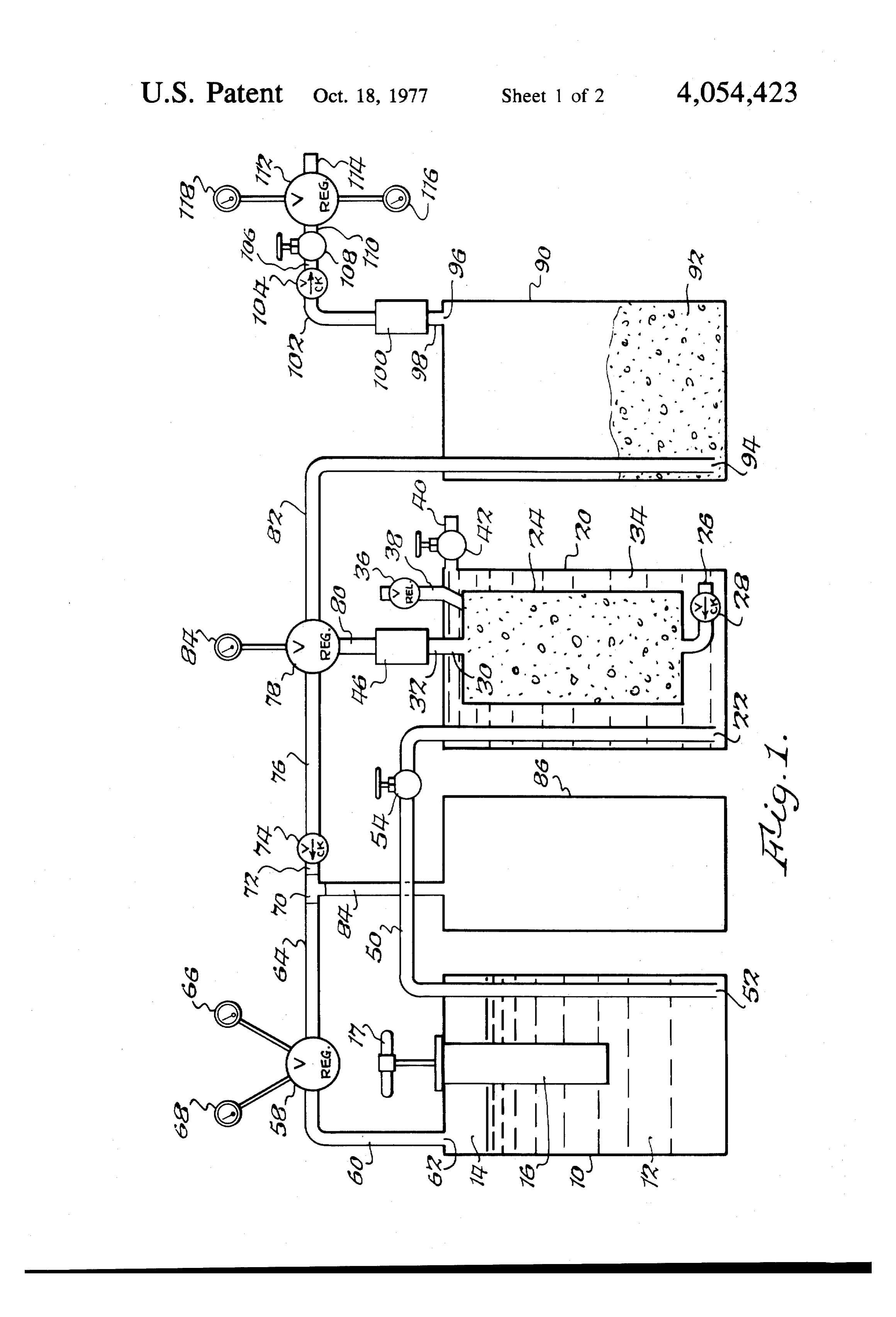
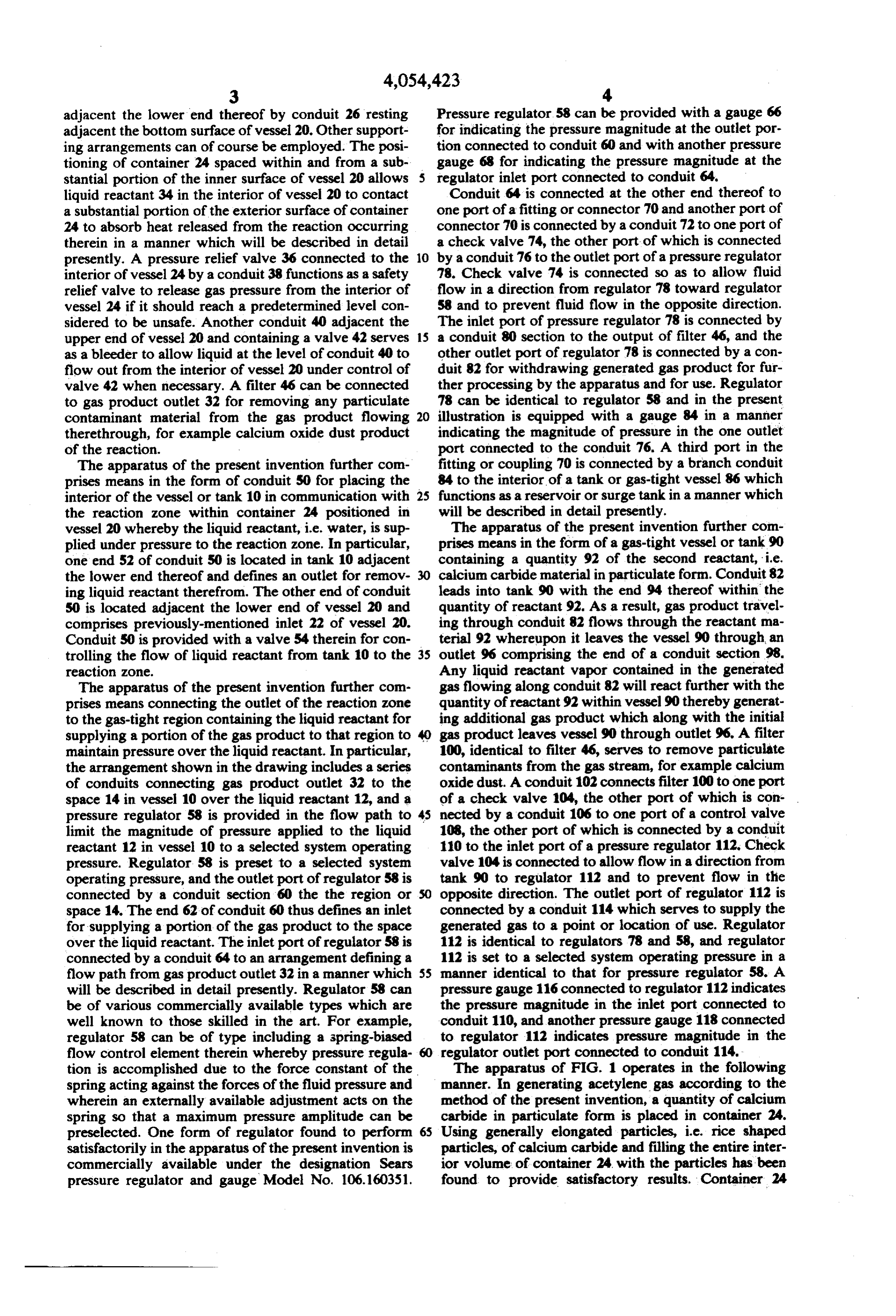
ing acetylene gas as a fuel for internal combustion en 10 DETALED DESCRIPTION OF THE gines, although the principles of the present invention ILLUSTRATED EMBODIMENTS can be variously applied. For vehicle engines it would Referring now to FIG. 1, there is shown apparatus be highly desirable to provide on board generation of according to the present invention for generating gas aceylene gas to avoid the need to store the gas in the 15 from the reaction between a first reactant in liquid form, vehicle which storage can give rise to problems of safety and of vehicle design to accommodate the stor in in the present illustration water, and a second reactant, age tank. In generating acetylene on board a vehicle, it erated the present illustration calcium carbide, the gas gen is important that such generation meet the demand or tus by the reaction being acetylene gas. The appara fuel requirement of the engine in a manner which does 20 tank 10 definingmeans comprises in the form of a gas-tight vessel or not result in overproduction of the acetylene gas. Fur which contains athe gas-tight region in the interior thereof thermore, the acetylene gas should be supplied to the stance a quantity of liquid reactant, in the present in water designated 12. As shown in engine in a manner providing efficient engine operation. FIG. 1, water 12 occupies a major portion of the vol SUMMARY OF THE INVENTION ume of the interior region of vessel 10, but does not It is, therefore, an object of this invention to provide 25 completely region 14 of fill the same so as to leave an empty space or the sealed interior above the water 12. The a new and improved method and apparatus for generat apparatus further comprises means for pressurizing the ing acetylene gas from the chemical reaction between space 14 over the water 12 in vessel 10, the pressurizing calcium carbide and water.
It is a further object of this invention to provide such with vessel 10 and operating16 by means comprising a pump operatively associated a method and apparatus wherein the rate of gas genera applied exteriorly of vessel 10 anda having mechanical input a pressure tion is efficiently and effectively controlled. output within vessel 10 in communication with the It is a further object of this invention to provide such upper portion of the interior region of the vessel. Pump a method and apparatus for use on a vehicle to supply 16 can be of the manually-operating type having a han fuel to the vehicle internal combustion engine in an 35 dle 17 extending out from the vessel or tank 10 which efficient manner and not resulting in overproduction of when reciprocated pumps or pressurizes the interior of acetylene gas. vessel 10 in a known manner similar to hand pumps The present invention provides a method and appara provided on spray guns or similar devices. Alterna tus for generating acetylene gas by the reaction between tively, pump 16 could comprise a compressor separate water and calcium carbide wherein an enclosed quan from vessel 10 wherein the pressure output is connected tity of water is pressurized by means such as a pump to by suitable conduit means to the interior of vessel 10. force feed the water to a reaction zone containing par The apparatus of the present invention further com ticulate calcium carbide. A portion of the acetylene gas prises means defining a gas-tight reaction zone contain product is pressure regulated and returned to the en ing the second reactant, in the present illustration solid closed quantity of water to maintain a regulated system 45 calcium carbide in particulate form, and having a gas operating pressure on the water. The water fed to the product outlet for removing generated gas. In particu reaction can be used to absorb heat released by the lar, there is provided a gas-tight vessel or tank 20 having reaction, and the output acetylene gas product can be an inlet 22 for admitting liquid reactant supplied thereto passed through another quantity of particulate calcium from tank 10. A gas-tight housing or container 24 is carbide whereby any water vapor in the gas reacts with positioned in the interior of vessel 20 and contains the the calcium carbide to generate additional acetylene. second reactant, in the present illustration solid calcium The generation of acetylene gas can be done on board a carbide in particulate form. Housing 24 has an inlet at vehicle to supply fuel to the internal combustion engine one end in the form of a relatively short conduit 26 in thereof in which case the acetylene gas is pre-mixed communication with the interior of vessel 20 to admit with air prior to additional mixing with air in the engine 55 the liquid reactant contained therein. A check valve 28 carburetor. in conduit 26 allows the liquid, i.e. water, to flow from The foregoing and additional advantages and charac the interior of vessel 20 into container 24 but prevents terizing features of the present invention will become flow from the interior of container 24 to the interior of clearly apparent upon a reading of the ensuing detailed vessel 20. The interior of container 24 at the other end description together with the included drawing is connected by a conduit 30 to a gas product outlet 32 wherein: of vessel 20. Thus, gas product, i.e. acetylene, generated BRIEF DESCRIPTION OF THE DRAWING by the reaction which occurs in container 24 leaves the
FIGURES
portion of the apparatus including vessel 20 and con tainer 24 through outlet 32. Container 24 is suitably
FIG. 1 is a diagrammatic view of apparatus for gener 65 fixed in position within the interior of vessel 20 and ating acetylene gas according to the present invention; generally centrally thereof, and in the present illustra FIG. 2 is a diagrammatic view showing a vehicle tion container 24 is held at the upper end thereof by the equipped with the apparatus of the present invention to connection of conduit 30 to outlet 32 and is supported
Page 5
adjacent the lower end thereof by conduit 26 resting Pressure regulator. 58 can be provided with a gauge 66 adjacent the bottom surface of vessel 20. Other support for indicating the pressure magnitude at the outlet por ing arrangements can of course be employed. The posi tion connected to conduit 60 and with another pressure tioning of container 24 spaced within and from a sub gauge 68 for indicating the pressure magnitude at the stantial portion of the inner surface of vessel 20 allows regulator inlet port connected to conduit 64. liquid reactant 34 in the interior of vessel 20 to contact Conduit 64 is connected at the other end thereof to a substantial portion of the exterior surface of container one port of a fitting or connector 70 and another port of 24 to absorb heat released from the reaction occurring connector 70 is connected by a conduit 72 to one port of therein in a manner which will be described in detail a check valve 74, the other port of which is connected presently. A pressure relief valve 36 connected to the 10 by a conduit 76 to the outlet port of a pressure regulator interior of vessel 24 by a conduit 38 functions as a safety 78. Check valve 74 is connected so as to allow fluid relief valve to release gas pressure from the interior of flow in a direction from regulator 78 toward regulator vessel 24 if it should reach a predetermined level con 58 and to prevent fluid flow in the opposite direction. sidered to be unsafe. Another conduit 40 adjacent the The inlet port of pressure regulator 78 is connected by upper end of vessel 20 and containing a valve 42 serves 15 a conduit 80 section to the output of filter 46, and the as a bleeder to allow liquid at the level of conduit 40 to other outlet port of regulator 78 is connected by a con flow out from the interior of vessel 20 under control of duit 82 for withdrawing generated gas product for fur valve 42 when necessary. A filter 46 can be connected ther processing by the apparatus and for use. Regulator to gas product outlet 32 for removing any particulate 78 can be identical to regulator 58 and in the present contaminant material from the gas product flowing 20 illustration is equipped with a gauge 84 in a manner therethrough, for example calcium oxide dust product indicating the magnitude of pressure in the one outlet of the reaction. port connected to the conduit 76. A third port in the The apparatus of the present invention further com fitting or coupling 70 is connected by a branch conduit prises means in the form of conduit 50 for placing the 84 to the interior of a tank or gas-tight vessel 86 which interior of the vessel or tank 10 in communication with 25 functions as a reservoir or surge tank in a manner which the reaction zone within container 24 positioned in will be described in detail presently. vessel 20 whereby the liquid reactant, i.e. water, is sup The apparatus of the present invention further com plied under pressure to the reaction zone. In particular, prises means in the form of a gas-tight vessel or tank 90 one end 52 of conduit 50 is located in tank 10 adjacent containing a quantity 92 of the second reactant, i.e. the lower end thereof and defines an outlet for remov calcium carbide material in particulate form. Conduit 82 ing liquid reactant therefrom. The other end of conduit leads into tank 90 with the end 94 thereof within the 50 is located adjacent the lower end of vessel 20 and quantity of reactant 92. As a result, gas product travel comprises previously-mentioned inlet 22 of vessel 20. ing through conduit 82 flows through the reactant ma Conduit 50 is provided with a valve 54 therein for con terial 92 whereupon it leaves the vessel 90 through, an trolling the flow of liquid reactant from tank 10 to the 35 outlet 96 comprising the end of a conduit section 98. reaction zone. Any liquid reactant vapor contained in the generated The apparatus of the present invention further com gas flowing along conduit 82 will react further with the prises means connecting the outlet of the reaction zone quantity of reactant 92 within vessel 90 thereby generat to the gas-tight region containing the liquid reactant for ing additional gas product which along with the initial supplying a portion of the gas product to that region to gas product leaves vessel 90 through outlet 96. A filter maintain pressure over the liquid reactant. In particular, 100, identical to filter 46, serves to remove particulate the arrangement shown in the drawing includes a series contaminants from the gas stream, for example calcium of conduits connecting gas product outlet 32 to the oxide dust. A conduit 102 connects filter 100 to one port space 14 in vessel 10 over the liquid reactant 12, and a of a check valve 104, the other port of which is con pressure regulator 58 is provided in the flow path to 45 nected by a conduit 106 to one port of a control valve limit the magnitude of pressure applied to the liquid 108, the other port of which is connected by a conduit reactant 12 in vessel 10 to a selected system operating 110 to the inlet port of a pressure regulator 112. Check pressure. Regulator 58 is preset to a selected system valve 104 is connected to allow flow in a direction from operating pressure, and the outlet port of regulator 58 is tank 90 to regulator 112 and to prevent flow in the connected by a conduit section 60 the the region or opposite direction. The outlet port of regulator 112 is space 14. The end 62 of conduit 60 thus defines an inlet connected by a conduit 114 which serves to supply the for supplying a portion of the gas product to the space generated gas to a point or location of use. Regulator over the liquid reactant. The inlet port of regulator 58 is 112 is identical to regulators 78 and 58, and regulator connected by a conduit 64 to an arrangement defining a 112 is set to a selected system operating pressure in a flow path from gas product outlet 32 in a manner which 55 manner identical to that for pressure regulator 58. A will be described in detail presently. Regulator 58 can pressure gauge 116 connected to regulator 112 indicates be of various commercially available types which are the pressure magnitude in the inlet port connected to well known to those skilled in the art. For example, conduit 110, and another pressure gauge 118 connected regulator 58 can be of type including a spring-biased to regulator 112 indicates pressure magnitude in the flow control element therein whereby pressure regula regulator outlet port connected to conduit 114. tion is accomplished due to the force constant of the The apparatus of FIG. 1 operates in the following spring acting against the forces of the fluid pressure and manner. In generating acetylene gas according to the wherein an externally available adjustment acts on the method of the present invention, a quantity of calcium spring so that a maximum pressure amplitude can be carbide in particulate form is placed in container 24. preselected. One form of regulator found to perform 65 Using generally elongated particles, i.e. rice shaped satisfactorily in the apparatus of the present invention is particles, of calcium carbide and filling the entire inter commercially available under the designation Sears ior volume of container 24, with the particles has been pressure regulator and gauge Model No. 106.160351. found to provide satisfactory results. Container 24
Page 6
would have a suitable opening with movable closure The generated gas pressure in surge tank 86 increases to element (not shown) to receive the particulate material, a magnitude equal to the generated gas pressure at the the mounting arrangement for container 24 in vessel 20 output of regulator 78. Due to the fact that reverse gas would be releasable, and vessel 20 would have a suitable flow is prevented by check valve 74, if the pressure at opening with movable closure element (not shown) to regulator 78 drops, the gas in surge tank 86 will not
receive the filled container 24 whereby the supply of return to regulator 78. If the pressure at the output of calcium carbide can be periodically replenished as it is regulator 58 decreases, however, gas will flow from consumed by operation of the apparatus. surge tank 86 into regulator 58 and then into region 14 With the filled container 24 in place within vessel 20 O to compensate for the decrease in system operating pressure. Thus regulator 58 and the portion of the appa and with vessel 20 sealed closed, a quantity of liquid ratus operatively reactant in the form of water is introduced to the appa 32 maintains the connecting desired it to the gas product outlet system operating pressure on ratus in the following manner. The vessel or tank 10 the water supply in tank 10 to sustain would have a suitable liquid inlet provided with a gas water to the reaction zone to sustain the the feeding of chemical reac tight closure element (not shown) adjacent the upper 15 tion producing acetylene gas. In addition, this is done portion of tank 10 as viewed in FIG. 1. With valve 54 a manner which avoids overproduction of the gas. in closed, water is introduced to tank 10 up to a level The useable gas pressure is the gas pressure which is below the top of the tank sufficient to leave the empty available in conduit 114 at the output of regulator 112. region or space 14. This pressure, which is indicated by gauge 118, should The next phase of the start-up procedure is pressuriz be ing the interior space 14 in tank 10 above the liquid 12. surekept at least 5 p.s.i. below the system operating pres and, for example, should be no more than 10 p.s.i.
This is done by manually operating pump 16, i.e. by with a system operating pressure of 15 p.s. i. As useable reciprocating handle 17, to increase the pressure in gas output in conduit 114 is consumed, the gas pressure region 14 and acting on the quantity of water 12. As the pressure is increased, water forced along conduit 50 25 in tanks 20 and 90 decreases, and when this pressure cannot flow past the closed valve 54, but the pressure is falls below the system operating pressure, the pressure sensed by meter 66 of regulator 58 which is connected acting on water 12 in tank 10 forces more water into to region 14 by conduit 60. The pump 16 is operated container 24 to generate additional gas which results in until the desired system operating pressure is reached as awith build-up of gas pressure again in tank 20 and 90. Thus, regulator 58 set at the desired system operating indicated by gauge 66, and, for example, in a small scale pressure, for example 15 p.s.i., when the generated gas gas generator a system operating pressure of about 15 p.s. i. was found to provide satisfactory results. pressure is greater than 15 p.s.i. there is no further gas The apparatus now is in condition to begin generating generation and when the generated gas pressure is less acetylene gas, and when valve 54 is opened, the pres than 15 p.s. i. additional gas is generated. This cyclic sure in region 14 forces water along conduit 50 to feed manner of operation continues until all of the water or it into vessel 20 and then through conduit 26 and valve 35 calcium carbide is consumed. Valve 108 serves as a shut-off valve when it is desired to stop the output flow 28 into container 24. The water reacts with calcium carbide in container 24 to produce acetylene gas ac of gas product, and valve 54 can be closed when the apparatus is to be inoperative for a significant amount of cording to the well known chemical reaction. The time.
water accumulating in tank 20 surrounds container 24, 40 vides Thus for the apparatus of the present invention pro efficient and effective control of the rate of gas contacting a major portion of the outer surface thereof, generation and avoids overproduction of gas. and serves to absorb heat from container 24 released by Heat is released during the chemical reaction between the chemical reaction therein and thus functions as a the water and calcium carbide in container 24. The coolant. The acetylene gas product leaves container 24 water in vessel 20 serves as a coolant through conduit 30 and outlet 32, flows through filter water enters container 24 to react withandthethis same 46 which removes particulate contaminants such as 45 carbide. If sufficient heat remains in containercalcium 24 to calcium oxide dust, and then flows into regulator 78 vaporize some of the incoming water, the acetylene from which a portion leaves through conduit 82 for leaving through outlet 32 will contain some water gas va further processing and use and from which the remain der leaves through conduit 76 for maintaining the sys por. This gas and waterflows along conduit 82 and then tem operating pressure in a manner which now will be 50 rises upwardly through the quantity 92 of calcuim car described. bide in tank 90 wherein the water vapor reacts with the As the generated gas pressure in the system increases, calcium carbide thereby generating additional acetylene water will continue to flow until the generated gas gas and removing the water vapor. Thus, additional gas pressure equals the pressure acting on the water. In is produced and the output gas is dry.
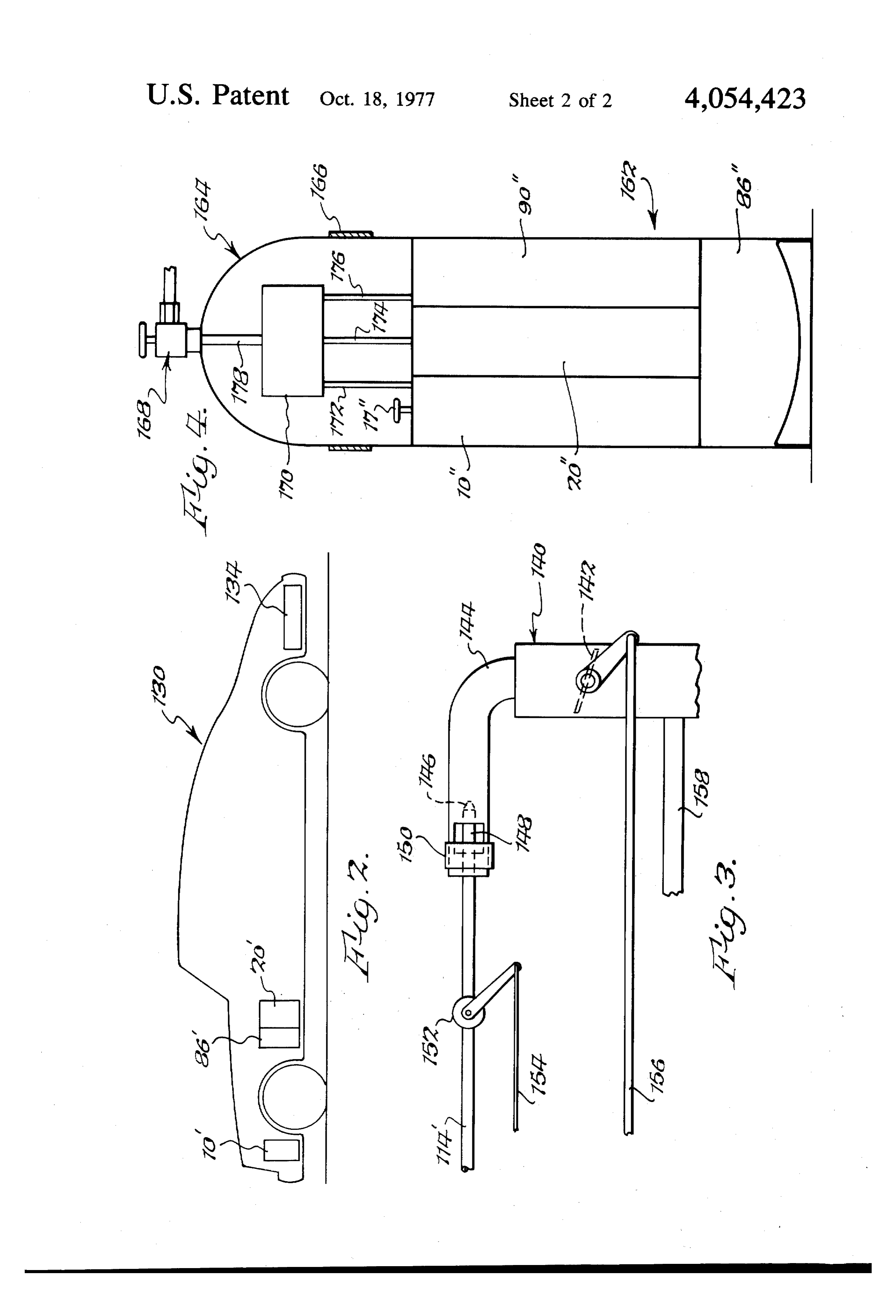
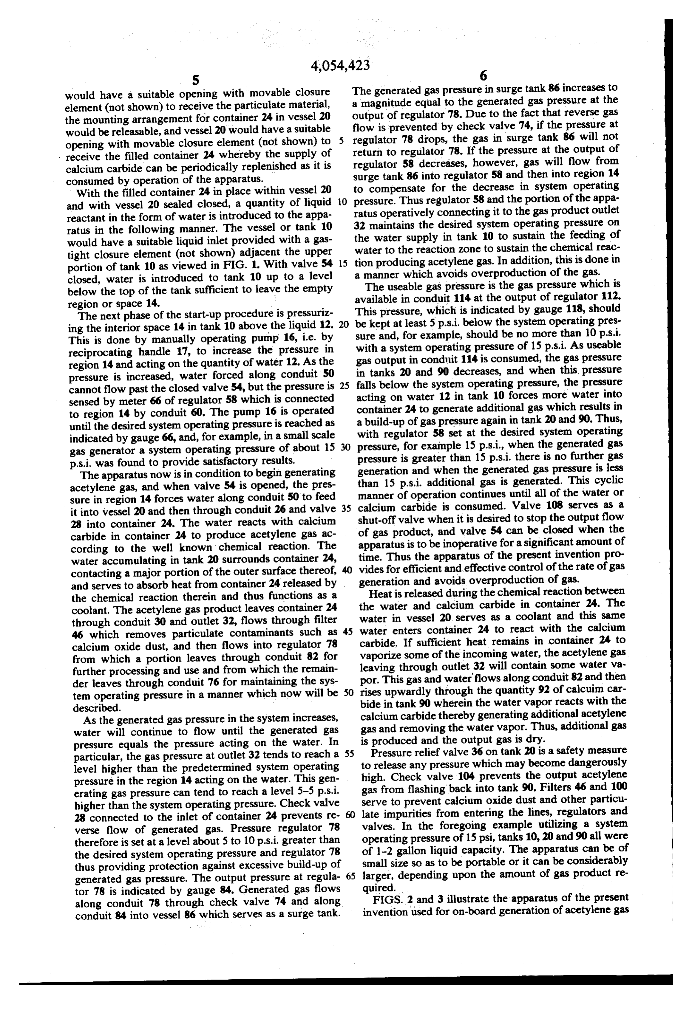
particular, the gas pressure at outlet 32 tends to reach a 55 to Pressure relief valve 36 on tank 20 is a safety measure release any pressure which may become dangerously level higher than the predetermined system operating high. Check valve 104 prevents the output acetylene pressure in the region 14 acting on the water. This gen erating gas pressure can tend to reach a level 5-5 p.s.i. serve gas from flashing back into tank 90. Filters 46 and 100 higher than the system operating pressure. Check valve late impuritiesto prevent calcium oxide dust and other particu 28 connected to the inlet of container 24 prevents re valves. In the from entering the lines, regulators and foregoing example utilizing a system verse flow of generated gas. Pressure regulator 78 operating pressure of 15 psi, tanks 10, 20 and 90 all were therefore is set at a level about 5 to 10 p.s. i. greater than of the desired system operating pressure and regulator 78 1-2 gallon liquid capacity. The apparatus can be of thus providing protection against excessive build-up of larger,size small so as to be portable or it can be considerably depending upon the amount of gas product re generated gas pressure. The output pressure at regula 65 tor 78 is indicated by gauge 84. Generated gas flows quired. FIGS. 2 and 3 illustrate the apparatus of the present along conduit 78 through check valve 74 and along invention used for on-board generation of acetylene gas conduit 84 into vessel 86 which serves as a surge tank.
Page 7
as fuel for the internal combustion engine of a vehicle. inactive gases, to the carbureator by means of conduit A conventional automobile 130 is powered by a stan 158.
dard internal combustion engine which can use as fuel The advantages of the apparatus of the present inven acetylene gas generated by the apparatus of the present tion for on-board generation of acetylene gas as fuel for invention. The automobile can use either acetylene or internal combustion engines are illustrated further by conventional gasoline as fuel but not both simulta the following calculations. The heating value of one neously. FIG. 2 illustrates a typical installation of the gallon of gasoline is equal to 115,000 BTU per gallon, apparatus of the present invention wherein the water and since gasoline weighs 7 pounds per gallon, in each tank 10" can be placed under the hood of vehicle 130 at pound of gasoline the heating value is 16,428.571 BTU. the front end thereof and the reaction vessel. 20' and O The heating value of one gram of acetylene is 47.6110 surge tank 86 also can be located under the hood rear BTU, and since there are about 453.6 grams in one wardly of tank 10'. Tank 90' can be located adjacent pound, one pound of acetylene by weight has a heating tank 20' laterally thereof. A conventional gasoline stor capacity of 21,596.311 BTU.
age tank is designated 134, and if vehicle 130 is to oper ate only on acetylene gas, then tank 10" can be placed in 15 ofWhen acetylene is compared to one gallon of gasoline gasoline by weight, i.e. 7 pounds of gasoline and 7 the location of gasoline tank 134. Appropriate controls pounds of acetylene, and gauges would be provided in the vehicle dash then 151,174.17 BTUthe heating value of acetylene is board, and controls for the acetylene generating appara gasoline that has a heating valueto115,000 compared the one gallon of
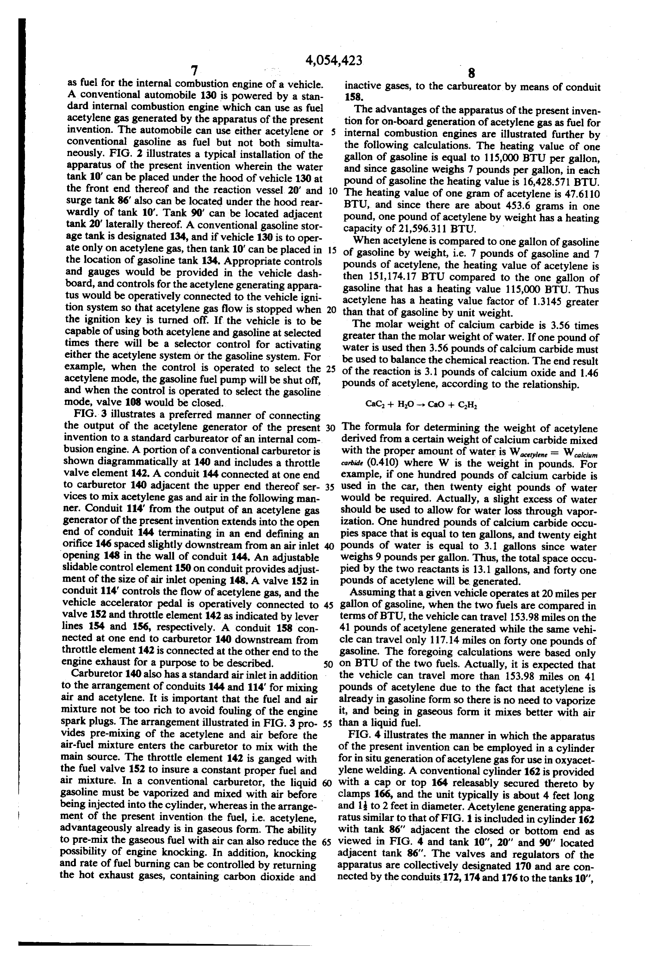
BTU. Thus tus would be operatively connected to the vehicle igni acetylene has a heating value factor of 1.3145 greater tion system so that acetylene gas flow is stopped when 20 than that of gasoline by unit weight. the ignition key is turned off. If the vehicle is to be The molar weight of calcium carbide is 3.56 times capable of using both acetylene and gasoline at selected greater times there will be a selector control for activating water isthan used the molar weight of water. If one pound of then 3.56 pounds of calcium carbide must either the acetylene system or the gasoline system. For be used to balance the chemical reaction. The end result example, when the control is operated to select the 25 of the reaction is 3.1 pounds of calcium oxide and 1.46 acetylene mode, the gasoline fuel pump will be shut off, pounds of acetylene, according to the relationship. and when the control is operated to select the gasoline mode, valve 108 would be closed. CaC -- HO-> CaO + CH
FIG. 3 illustrates a preferred manner of connecting the output of the acetylene generator of the present The formula for determining the weight of acetylene invention to a standard carbureator of an internal com derived from a certain weight of calcium carbide mixed busion engine. A portion of a conventional carburetor is with the proper amount of water is Waceylene = Walcium shown diagrammatically at 140 and includes a throttle carbide (0.410) where W is the weight in pounds. For valve element 142. A conduit 144 connected at one end example, if one hundred pounds of calcium carbide is to carburetor 140 adjacent the upper end thereof ser 35 used in the car, then twenty eight pounds of water vices to mix acetylene gas and air in the following man would be required. Actually, a slight excess of water ner. Conduit 114 from the output of an acetylene gas should be used to allow for water loss through vapor generator of the present invention extends into the open ization. One hundred pounds of calcium carbide occu end of conduit 144 terminating in an end defining an pies space that is equal to ten gallons, and twenty eight orifice 146 spaced slightly downstream from an air inlet pounds of water is equal to 3.1 gallons since water opening 148 in the wall of conduit 144. An adjustable weighs 9 pounds per gallon. Thus, the total space occu slidable control element 150 on conduit provides adjust pied by the two reactants is 13.1 gallons, and forty one ment of the size of air inlet opening 148. A valve 152 in pounds of acetylene will be generated. conduit 114 controls the flow of acetylene gas, and the Assuming that a given vehicle operates at 20 miles per vehicle accelerator pedal is operatively connected to 45 gallon of gasoline, when the two fuels are compared in valve 152 and throttle element 142 as indicated by lever terms of BTU, the vehicle can travel 153.98 miles on the lines 154 and 156, respectively. A conduit 158 con 41 pounds of acetylene generated while the same vehi nected at one end to carburetor 140 downstream from cle can travel only 117.14 miles on forty one pounds of throttle element 142 is connected at the other end to the gasoline. The foregoing calculations were based only engine exhaust for a purpose to be described. 50 on BTU of the two fuels. Actually, it is expected that Carburetor 140 also has a standard air inlet in addition the vehicle can travel more than 153.98 miles on 41 to the arrangement of conduits 144 and 114 for mixing pounds of acetylene due to the fact that acetylene is air and acetylene. It is important that the fuel and air already in gasoline form so there is no need to vaporize mixture not be too rich to avoid fouling of the engine it, and being in gaseous form it mixes better with air spark plugs. The arrangement illustrated in FIG. 3 pro 55 than a liquid fuel.
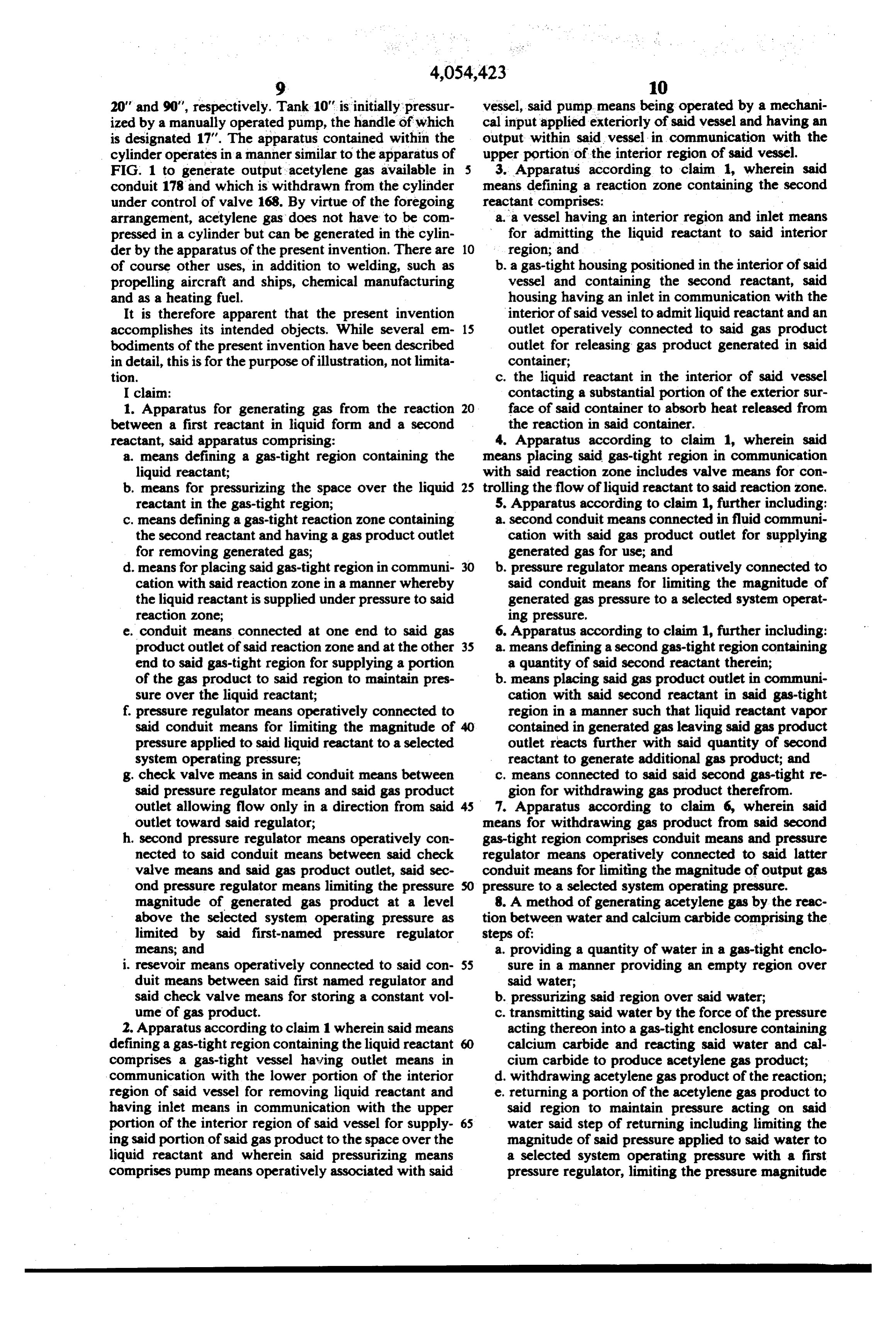
vides pre-mixing of the acetylene and air before the FIG. 4 illustrates the manner in which the apparatus air-fuel mixture enters the carburetor to mix with the of the present invention can be employed in a cylinder main source. The throttle element 142 is ganged with for in situ generation of acetylene gas for use in oxyacet the fuel valve 152 to insure a constant proper fuel and ylene welding. A conventional cylinder 162 is provided air mixture. In a conventional carburetor, the liquid with a cap or top 164 releasably secured thereto by gasoline must be vaporized and mixed with air before clamps 166, and the unit typically is about 4 feet long being injected into the cylinder, whereas in the arrange and 1 to 2 feet in diameter. Acetylene generating appa ment of the present invention the fuel, i.e. acetylene, ratus similar to that of FIG. 1 is included in cylinder 162 advantageously already is in gaseous form. The ability with tank 86' adjacent the closed or bottom end as to pre-mix the gaseous fuel with air can also reduce the 65 viewed in FIG. 4 and tank 10", 20' and 90' located possibility of engine knocking. In addition, knocking adjacent tank 86'. The valves and regulators of the and rate of fuel burning can be controlled by returning apparatus are collectively designated 170 and are con the hot exhaust gases, containing carbon dioxide and nected by the conduits 172,174 and 176 to the tanks 10",
Page 8
20" and 90", respectively. Tank 10" is initially pressur vessel, said pump means being operated by a mechani ized by a manually operated pump, the handle of which cal input applied exteriorly of said vessel and having an is designated 17". The apparatus contained within the output within said vessel in communication with the cylinder operates in a manner similar to the apparatus of upper portion of the interior region of said vessel. FIG. 1 to generate output acetylene gas available in 5 3. Apparatus according to claim 1, wherein said conduit 178 and which is withdrawn from the cylinder means defining a reaction zone containing the second under control of valve 168. By virtue of the foregoing reactant comprises:
arrangement, acetylene gas does not have to be com a.a vessel having an interior region and inlet means pressed in a cylinder but can be generated in the cylin for admitting the liquid reactant to said interior der by the apparatus of the present invention. There are 10 region; and of course other uses, in addition to welding, such as b. a gas-tight housing positioned in the interior of said propelling aircraft and ships, chemical manufacturing vessel and containing the second reactant, said and as a heating fuel. housing having an inlet in communication with the It is therefore apparent that the present invention interior of said vessel to admit liquid reactant and an accomplishes its intended objects. While several em 15 outlet operatively connected to said gas product bodiments of the present invention have been described outlet for releasing gas product generated in said in detail, this is for the purpose of illustration, not limita container;
tion. c. the liquid reactant in the interior of said vessel I claim: contacting a substantial portion of the exterior sur 1. Apparatus for generating gas from the reaction 20 face of said container to absorb heat released from between a first reactant in liquid form and a second the reaction in said container. reactant, said apparatus comprising: 4. Apparatus according to claim 1, wherein said a means defining a gas-tight region containing the means placing said gas-tight region in communication liquid reactant; with said reaction zone includes valve means for con b. means for pressurizing the space over the liquid 25 trolling the flow of liquid reactant to said reaction zone. reactant in the gas-tight region; 5. Apparatus according to claim 1, further including: c. means defining a gas-tight reaction zone containing a second conduit means connected in fluid communi the second reactant and having a gas product outlet cation with said gas product outlet for supplying for removing generated gas; generated gas for use; and d. means for placing said gas-tight region in communi 30 b. pressure regulator means operatively connected to cation with said reaction zone in a manner whereby said conduit means for limiting the magnitude of the liquid reactant is supplied under pressure to said generated gas pressure to a selected system operat reaction zone; ing pressure.
e. conduit means connected at one end to said gas 6. Apparatus according to claim 1, further including: product outlet of said reaction zone and at the other 35 a means defining a second gas-tight region containing end to said gas-tight region for supplying a portion a quantity of said second reactant therein; of the gas product to said region to maintain pres b. means placing said gas product outlet in communi sure over the liquid reactant; cation with said second reactant in said gas-tight f. pressure regulator means operatively connected to region in a manner such that liquid reactant vapor said conduit means for limiting the magnitude of 40 contained in generated gas leaving said gas product pressure applied to said liquid reactant to a selected outlet reacts further with said quantity of second system operating pressure; reactant to generate additional gas product; and g. check valve means in said conduit means between c. means connected to said said second gas-tight re said pressure regulator means and said gas product gion for withdrawing gas product therefrom. outlet allowing flow only in a direction from said 45 7. Apparatus according to claim 6, wherein said outlet toward said regulator; means for withdrawing gas product from said second h. second pressure regulator means operatively con gas-tight region comprises conduit means and pressure nected to said conduit means between said check regulator means operatively connected to said latter valve means and said gas product outlet, said sec conduit means for limiting the magnitude of output gas ond pressure regulator means limiting the pressure SO pressure to a selected system operating pressure. magnitude of generated gas product at a level 8. A method of generating acetylene gas by the reac above the selected system operating pressure as tion between water and calcium carbide comprising the limited by said first-named pressure regulator steps of:
means; and a. providing a quantity of water in a gas-tight enclo i. resevoir means operatively connected to said con 55 sure in a manner providing an empty region over duit means between said first named regulator and said water;
said check valve means for storing a constant vol b. pressurizing said region over said water; ume of gas product. c. transmitting said water by the force of the pressure 2. Apparatus according to claim 1 wherein said means acting thereon into a gas-tight enclosure containing defining a gas-tight region containing the liquid reactant calcium carbide and reacting said water and cal comprises a gas-tight vessel having outlet means in cium carbide to produce acetylene gas product; communication with the lower portion of the interior d. withdrawing acetylene gas product of the reaction; region of said vessel for removing liquid reactant and e. returning a portion of the acetylene gas product to having inlet means in communication with the upper said region to maintain pressure acting on said portion of the interior region of said vessel for supply 65 water said step of returning including limiting the ing said portion of said gas product to the space over the magnitude of said pressure applied to said water to liquid reactant and wherein said pressurizing means a selected system operating pressure with a first comprises pump means operatively associated with said pressure regulator, limiting the pressure magnitude
Page 9
of generated acetylene gas product at a level above being limited to a single direction toward said first said selected system operating pressure with a sect regulator; and ond pressure regulator, and storing a constant vol. f. absorb using the water transmitted to said enclosure to ume pof acetylene gas product obtained from the heat released by the reaction; and
product returned to said region for use in compens 5 g. tity passing the acetylene of particulate gas product calcium carbidethrough a quan whereby any sating for any decrease in the system operating . water vapor in the acetylene gas product reacts pressure, said stored gas product being at said pres- with the calcium carbide to produce additional sure level above said system operating pressure, and acetylene gas.
the flow of said returned acetylene gas product 10
Provenance
- Collection
- Cited prior art
- Original PDF
- patentimages.storage.googleapis.com →
- Filed
- 1975-07-21
- Pages
- 9
- Method
- pdftotext (the PDF's own text layer) + pdftoppm 300dpi page scans
- Source
- Google Patents bibliographic record
- Granted
- 1977-10-18
- Inventors
- Orman L. Blenman
- Transcribed from
- patentimages.storage.googleapis.com →