patent · US6053153
Internal combustion engine
25 April 2000
Page 1 — bibliographic record
United States Patent (19) 11 Patent Number: 6,053,153 MOSer et al. (45) Date of Patent: Apr. 25, 2000
54 INTERNAL COMBUSTION ENGINE 58 Field of Search ..................................... 123/557, 549,
75 Inventors: Winfried Moser, Ludwigsburg; Klaus
Joos, Walheim; Anwar Abidin, 56) References Cited
Leonberg, Georg Mallebrein, U.S. PATENT DOCUMENTS
Korntal-Muenchingen; Jorg Lange,
Eberdingen; Andreas Eichendorf, 2,322,991 6/1943 Wunsch et al. ......................... 123/557 Schorndorf; Christof Vogel, Bischberg; 3,618,579 11/1971 Varran . ... 123/557 Gerhard Benz, Boblingen; Nikolaus 4,329,964 5/1982 Morris ..... ... 123/557 Simon, Murnau, all of Germany 5,343,848 9/1994 Birch et al. . 123/557 5,408,973 4/1995 Spangjer ................................. 123/557 73 Assignee: Robert Bosch GmbH, Stuttgart, 5,711,282 1/1998 Lang et al. .............................. 123/557 Germany Primary Examiner Marguerite McMahon
Attorney, Agent, or Firm Ronald E. Greigg; Edwin E.
21 Appl. No.: 09/101,326 Greigg 22 PCT Filed: Sep. 30, 1997 57 ABSTRACT 86 PCT No.: PCT/DE97/02244 An internal combustion engine for motor vehicles, with an S371 Date: Nov. 6, 1998 intake tube for aspirating combustion air, in which the tube leads to at least one combustion cylinder, and in which tube
S 102(e) Date: Nov. 6, 1998 a throttle valve is disposed. The intake tube effects a mixing 87 PCT Pub. No.: WO98/20246 of combustion air and fuel vapor downstream of the throttle Valve. For the Sake of intensive mixing of fuel vapor and
PCT Pub. Date: May 14, 1998 combustion air into a largely homogeneous mixture, the fuel Vapor generated in a fuel evaporator outside the intake tube 30 Foreign Application Priority Data is introduced via a delivery device into air turbulence paths Nov. 7, 1996 DEI Germany ........................... 196 45819 that unavoidably develop downstream of the throttle valve in the intake tube as a consequence of the geometry of the 51) Int. Cl." .......................... F02M 31/18: FO2M 29/00; intake tube and/or throttle valve.
52 U.S. Cl. ............................................. 123/557; 123/549 19 Claims, 4 Drawing Sheets
Page 2
Drawing sheet — no readable text.
Page 3
Drawing sheet — no readable text.
Page 4
Drawing sheet — no readable text.
Page 5
Drawing sheet — no readable text.
Page 6
INTERNAL COMBUSTION ENGINE combustion cylinders, and to Stable combustion in the com bustion cylinders. The expulsion of hydrocarbons with the
PRIOR ART exhaust gas is reduced drastically, and the catalytic converter The invention relates to an internal combustion engine. can already begin converting very early after the engine has Started.
In Such an engine, to reduce the hydrocarbons contained Advantageous refinements of and improvements of the in the exhaust gas (raw HC emissions), the combustion internal combustion engine disclosed are possible with the cylinders of the cold engine upon cold Starting and during provisions recited herein.
the then ensuing warmup are Supplied centrally, via the intake tube, with fuel vapor mixed with combustion air. As Introducing the fuel vapor into the “natural” turbulence a result, combustion in the combustion cylinders proceeds in paths in the intake tube can be achieved by Suitable geo a highly stable and largely homogeneous way, and HC metrical definitions of the orifice of the fuel vapor delivery emissions are reduced drastically. In normal driving, device inside the intake tube.
conversely, the fuel vapor admixture is dispensed with, and In a preferred embodiment of the invention, to that end, the fuel is delivered to the combustion cylinders in the 15 the delivery device has at least two discharge openings, known way via the injection Valves. disposed diametrically near the intake tube wall, whose In one known method for mixing fuel vapor with com opening croSS Section in each case points in the flow bustion air in the central intake tube of the internal com direction, inclined by an angle of approximately 450 from bustion engine (Charles Aquino and Williams D. Plensdorf, the intake tube axis. The two discharge openings are each “An Evaluation of Local Heating as a Means of Fuel embodied on the face end of one of two diametrically Evaporation for Gasoline Engines, International CongreSS opposed orifice Stubs, which protrude radially from the and Exposition, Detroit, Michigan, Feb. 24-28, 1985, SAE intake tube wall and are joined via a Semicircular feed elbow, Technical Paper Series, 860 246, 1986), so-called swirl contacting the intake tube wall, to a feed Stub that penetrates Vanes disposed downstream of the throttle valve create the intake tube wall and is connected to the fuel evaporator. turbulence paths in the intake tube, into which paths fuel is 25 In an alternative embodiment of the invention, in a injected largely tangentially into the intake tube by means of version with a so-called register throttle valve, the delivery two injection valves disposed upstream of the throttle valve. device has a discharge opening, disposed in the region of the The fuel Spray introduced is carried by the turbulence along partitioning rib, whose opening croSS Section points in the heated Surfaces downstream of the Swirl Vanes in the intake flow direction, inclined by an angle of approximately 45 tube and is evaporated there. The resultant fuel vapor mixes from the intake tube axis. This discharge opening is embod intensively with the now-turbulent combustion air, thus ied on the face end of an orifice Stub, which penetrates the creating a largely homogeneous fuel-air mixture. The Swirl intake tube wall and extends into the region of the parti Vanes built into the intake tube for creating turbulence are tioning rib and is connected to the fuel evaporator. disadvantageous, however, in the Sense that they markedly BRIEF DESCRIPTION OF THE DRAWINGS throttle the aspirated air and thus lead to a considerable loSS 35 in power and efficiency. The invention is described in further detail below in terms ADVANTAGES OF THE INVENTION of exemplary embodiments shown in the drawings. Shown
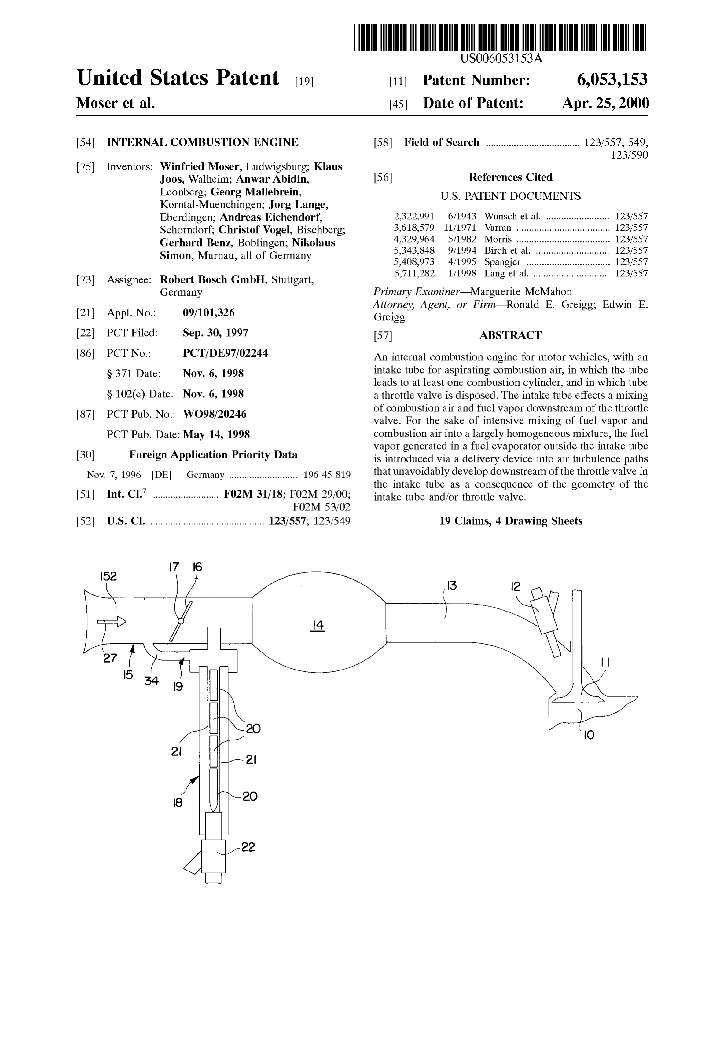
The internal combustion engine according to the FIG. 1, a fragmentary Schematic longitudinal Section invention, and the method of the invention employed in this 40 through an internal combustion engine with a combustion engine, have the advantage over the prior art that for the cylinder and an intake tube;
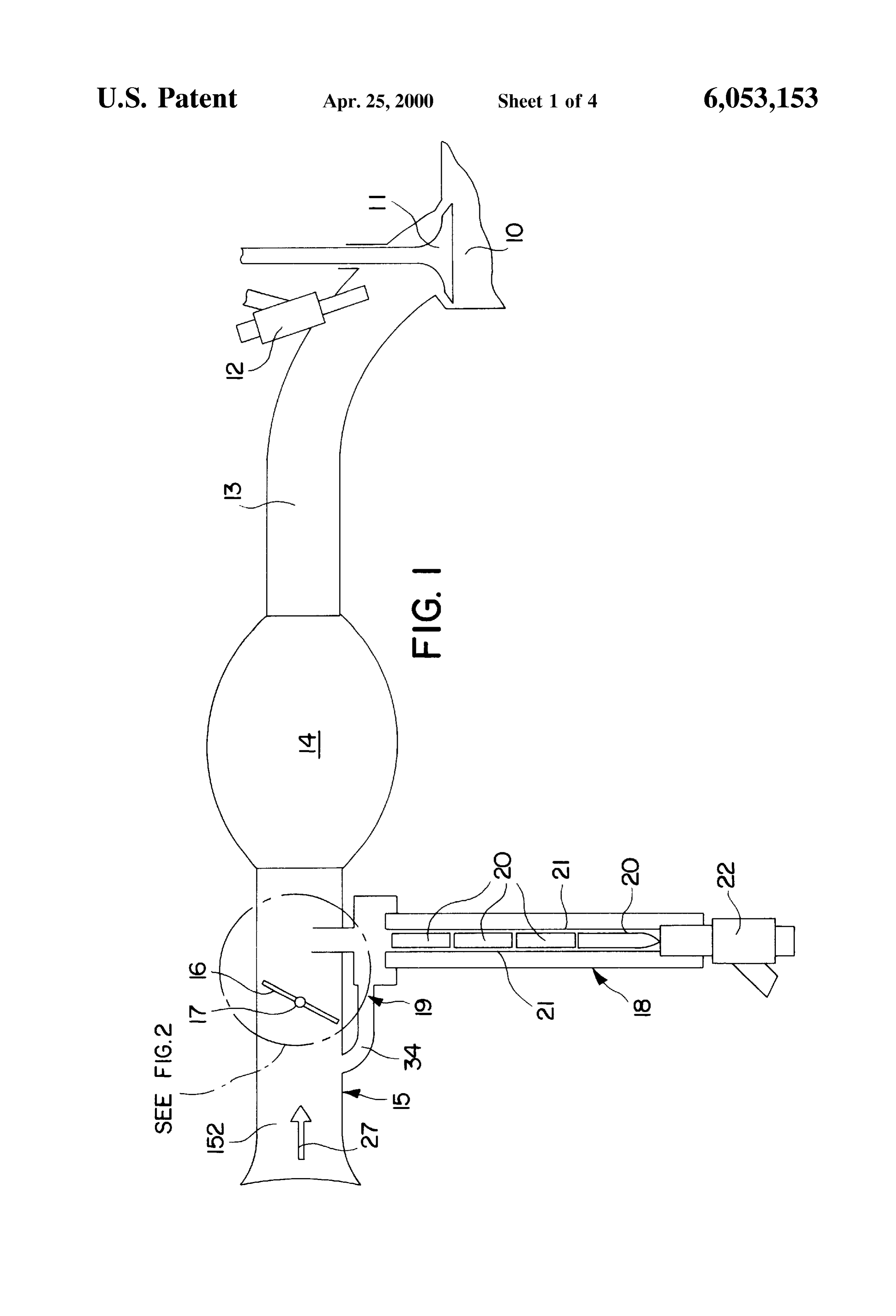
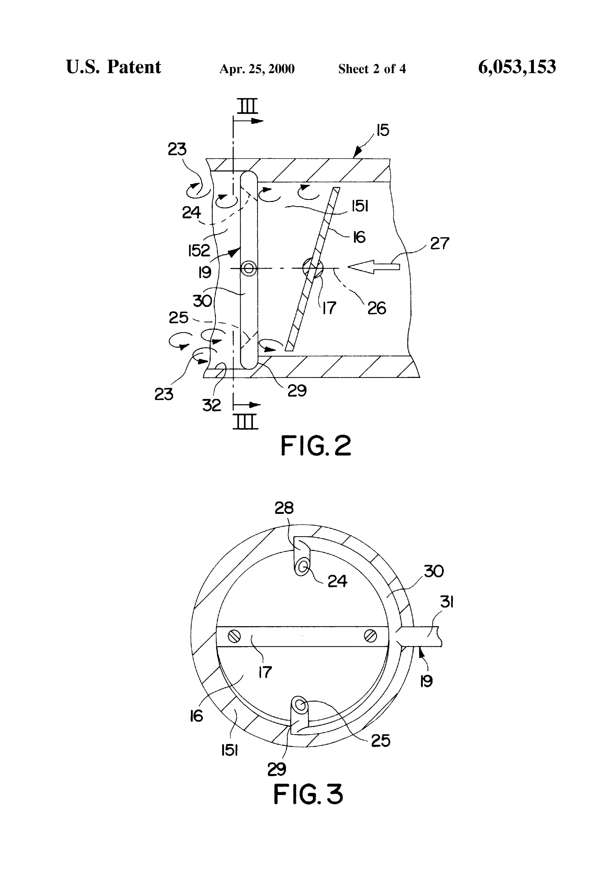
intensive mixing of fuel vapor and combustion air, no FIG. 2, an enlarged view of detail II in FIG. 1 in a built-in fixtures in the intake tube that reduce the power and constructional version;
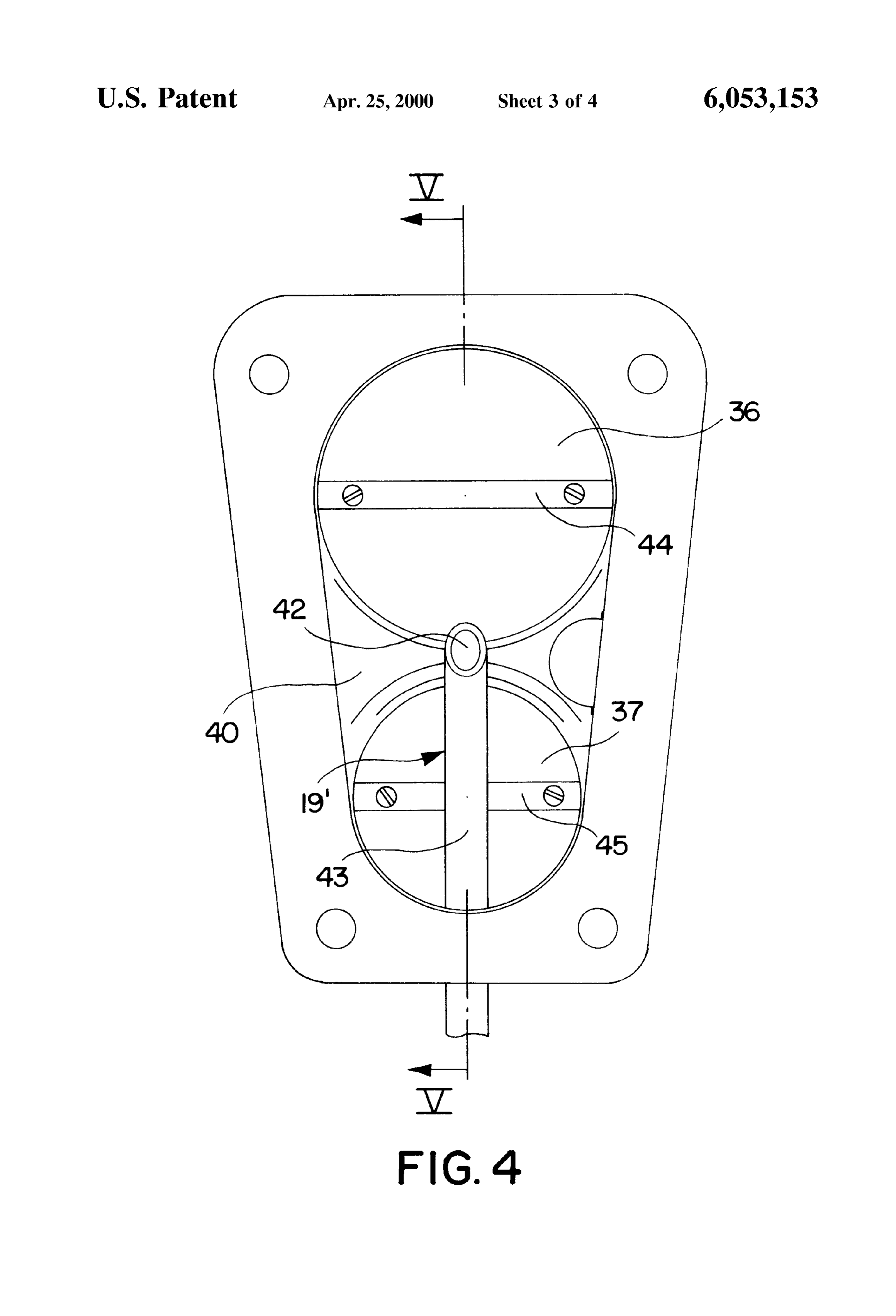
efficiency are provided; instead, the turbulence paths that are naturally present in the intake tube and that unavoidably 45 FIG. 3, a section taken along the line III-III of FIG. 2; develop because of the intake tube and/or throttle valve FIG. 4, a plan view on a modified intake tube of the geometry, which is already determined by other internal combustion engine with a So-called register throttle considerations, are utilized to make the fuel vapor generated valve;
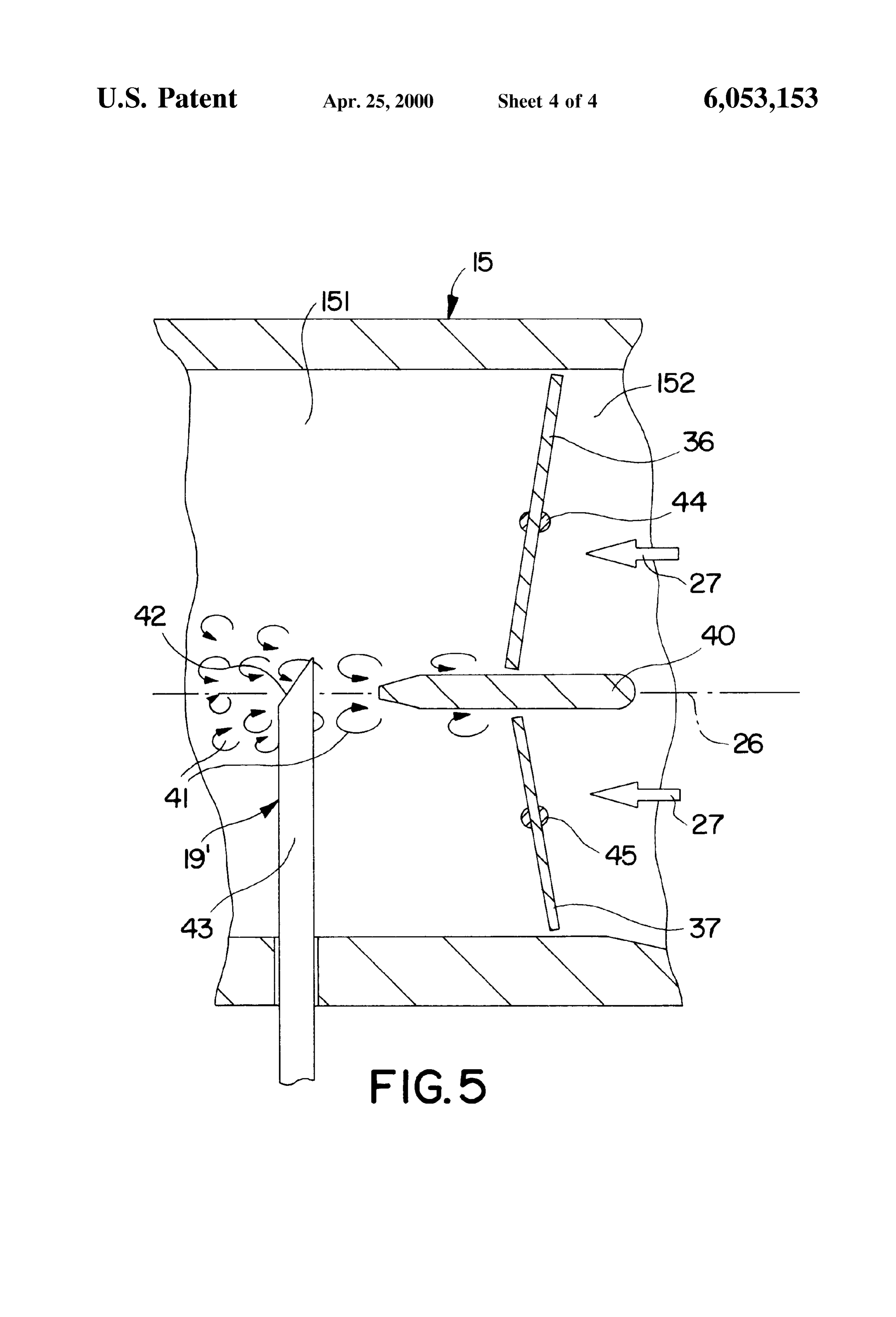
outside the intake tube turbulent. Such turbulence paths FIG. 5, a section taken along the line V-V of FIG. 4. develop at Structurally dictated discontinuities of the intake 50 DESCRIPTION OF THE EXEMPLARY tube wall and in particular at the edges of the throttle valve. EMBODIMENTS Compared with the intake tube without fuel vapor admixture for cold Starting and warmup, no additional flow resistances The internal combustion engine shown in fragmentary, develop as a result of the fuel Vapor admixture, compared Schematic form in longitudinal Section in FIG. 1 has a with the known central fuel vapor admixture, along with this 55 plurality of combustion cylinders, of which only one com advantage of improving power and efficiency, the Structural bustion cylinder 10 is shown in fragmentary form, with a expense in the intake tube is reduced. Because the fuel vapor Schematically indicated inlet Valve 11 and a fuel injection is generated outside the intake tube and introduced into the valve 12. Leading to the inlet valve 11 of the combustion air eddies, instead of the introduction of fuel Spray with cylinder 10 is a so-called Swing pipe 13, which like the other ensuing evaporation along heated Surfaces in the intake tube, 60 Swing pipes 13 for the other combustion cylinders 10 a very homogeneous mixture formation is achieved even branches off from a calming chamber 14. An intake tube 15 before the connections where the intake tube branches to of the engine opens into the calming chamber 14 and Serves lead to the individual combustion cylinders, and as a result to aspirate combustion air that is then carried to the inlet an exactly identical quality of the fuel-air mixture for the valves 11 of the combustion cylinders 10 via the individual individual combustion cylinderS is assured. This in turn 65 Swing pipes 13. The quantity of aspirated combustion air leads to identical operating conditions for all the combustion needed is controlled by means of a throttle valve 16, which cylinders, to a reduction in wall film development in the is pivotably supported in the intake tube 15 on a pivot shaft
Page 7
17 oriented transversely to the flow direction and can be discharge openings are disposed in Such a way-as pivoted out of a closing position, which covers the air flow described for the discharge openings 24, 25-that the fuel croSS Section of the intake tube 15, into an open position that Vapor flowing out of them is introduced into the turbulence opens the entire croSS Section of the intake tube, and Vice path 23 that develops at the circular circumference edge of Versa, and can also assume any intermediate position the throttle valve 16.
between them.
To improve hydrocarbon-emissions in the exhaust gas on In certain cases, air is also admixed with fuel vapor before cold Starting of the engine and ensuing warmup, in these itend-as is introduced into the intake tube portion 151. To that operating phases of the engine the combustion air aspirated device 19schematically sketched in FIG. 1-the delivery communicates via a conduit 34 with the intake via the intake tube 15 has fuel vapor added to it, which is tube portion 152 located immediately upstream of the mixed intensively with the combustion air so that the most homogeneous possible fuel-air mixture is Supplied to the throttle air is valve 16, so that a small portion of the combustion diverted from the intake tube 15, specifically in the combustion cylinders 10 via the inlet valves 11. To that end, intake tube portion 152, and is delivered via the delivery a fuel evaporator 18 is provided, which communicates with device 19, together with the fuel vapor, to the intake tube 15 the interior of the intake tube 15, via a delivery device 19. 15 again in the intake tube portion 151. The fuel evaporator 18 has convective heating surfaces 20, between which narrow flow gaps 21 of Small croSS Section of During normal driving modes, that is, after the conclusion the engine warmup phase, the fuel vapor generation and are kept open, and also has an injection valve 22 for injecting admixture of fuel vapor is stopped, and fuel delivery to the fuel into these flow gaps. The fuel injected by the injection valve 22 between the heating surfaces 20 is forced through combustion through the cylinders 10 is effected in the known way fuel injection valves 12.
the flow gaps 21 and is evaporated in the process. The resultant fuel vapor is delivered via the delivery device 19 to In the intake tube portion 151 of a modified intake tube the intake tube 15, in an intake tube portion 151 located 15, shown in FIGS. 4 and 5, the throttle valve is embodied immediately downstream of the throttle valve 16. The intro as a so-called register throttle valve 35. The register throttle duction of the fuel vapor is effected by a suitable disposition 25 valve 35 includes two circular valve parts 36, 37 of different and embodiment of the orifice of the delivery device 19 in diameters, the upper valve part 37 having the larger diam the intake tube portion 151 such that the fuel vapor enters a eter.
turbulence path of the combustion air that develops unavoid The two valve parts 36, 37 control two register openings, ably in the intake tube portion 151 because of the structur which are separated from one another by a partitioning rib ally dictated geometry of the intake tube and/or throttle 40 that extends as far as the wall of the intake tube. Each valve. Such turbulence paths unavoidably form at disconti Valve part 36, 37 is capable of closing the register opening, nuities in the wall Surface of the intake tube 15, for instance, respectively, associated with it, either completely or partially but in particular at the edges of the throttle valve 16. or of opening it completely So that air can pass through. In the intake tube portion 151 shown in FIGS. 2 and 3, the In a register throttle valve 35 embodied in this way in the fuel vapor is introduced into the turbulence path that 35 intake tube 15, the fuel vapor-optionally with the admix unavoidably develops along the edge of the throttle valve. ture of air-is introduced preferentially into the turbulence This turbulence path is represented in FIG. 2 by small flow path 41 (FIG. 5) that unavoidably develops at the partition arrows and identified in general by reference numeral 23. ing rib 40. To that end, the discharge opening 42 of the This turbulence path 23 develops over the entire circumfer delivery device 19" is disposed in the region of the parti ence of what in this case is a circular throttle valve 16. To 40 tioning rib 40, and once again its opening croSS Section introduce the fuel vapor generated by the fuel evaporator 18 points in the flow direction (arrow 27 in FIG. 5) inclined at into this turbulence path 23, the delivery device 19 has two an angle of about 45 to the intake tube axis 26. The discharge openings 24, 25, located near the wall of the intake discharge opening 42 is formed on the face end of an orifice tube, and their opening croSS Section is in each case inclined stub 43, which radially penetrates the intake tube wall and at an angle of approximately 45 to the axis 26 of the intake 45 extends as far as the region of the partitioning rib 40 and is tube 15 and points in the flow direction of the combustion connected to the fuel evaporator 18 (FIG. 1). air. The flow direction of the combustion air is indicated in The method for central admixing of fuel vapor with the FIGS. 1 and 2 by a flow arrow 27. Each of the discharge combustion air aspirated via the intake tube 15 on cold openings 24, 25 is embodied on the face end of a respective Starting of the internal combustion engine and in its warmup orifice stub 28 and 29 that protrudes radially from the wall 50 phase, which is realized in the internal combustion engine of the intake tube. The two orifice stubs 28, 29 are located described above in two exemplary embodiments, is thus diametrically opposite one another along the intake tube axis distinguished in Summary form in that the fuel vapor is 26 and are connected to a feed Stub 31 via a Semicircular generated outside the intake tube 15 and is introduced into feed elbow 30 extending between the two orifice stubs 28, air turbulence paths 23 and 41 that unavoidably develop 29. The feed stub 31 that opens into the feed elbow 30 passes 55 downstream of the throttle valve 16 or 35 in the intake tube radially through the wall of the intake tube 15 and commu 15 as a consequence of the geometry of the intake tube nicates with the outlet of the fuel evaporator 18. The feed and/or the throttle Valve. It is a decisive advantage that no elbow 30 is placed in a semicircular recess 32 in the intake additional provisions for making the air turbulent in the tube wall and is braced on the annular shoulder 33 formed intake tube 15 and that present increased flow resistance to on the end of the recess 32. 60 the aspirated air Stream and by throttling this aspirated air It is understood that Still other discharge openings may be Stream reduce the power and efficiency are taken but instead provided in the delivery device 19 of FIGS. 2 and 3; they that recourse is made to “naturally occurring turbulence will be embodied in the same way as the discharge openings paths 23 and 41, into which the fuel vapor, generated outside 24, 25 but are offset by certain circumferential angles from the intake tube 15, is introduced directly. These “natural” air them. These additional discharge openings are also formed 65 eddies are maximally well Suited for intensive mixing of fuel on the free ends of orifice stubs, which communicate with Vapor and aspirated air and thereby of delivering a homo the feed stub 31 via corresponding feed elbows. All of these geneous fuel-air mixture to the combustion cylinderS 10 via
Page 8
S 6 the inlet valves 11, the quality of the fuel-air mixture being 9. The engine according to claim 4, in which the fuel the same for all the combustion cylinders 10. The combus evaporator (18) has convective heating surfaces (20), with tion thus proceeds very stably and extraordinarily homoge flow gaps (21) of Smaller croSS Section located between neously in all the combustion cylinders 10. As a result, the them, and also has an injection valve (22) for injecting fuel raw HC emissions of the cold engine can be drastically into the flow gaps (21).
reduced, and at the same time engine operating conditions 10. The engine according to claim 2, in which the intake can be achieved that allow the catalytic converter to begin tube (15) is followed by a calming chamber (14), and that conversion quite Soon after the engine Starts. from the calming chamber (14), Swing pipes (13) each lead The foregoing relates to preferred exemplary embodi to one of a plurality of combustion cylinders (10). ments of the invention, it being understood that other 11. The engine according to claim 3, in which the intake variants and embodiments thereof are possible within the tube (15) is followed by a calming chamber (14), and that Spirit and Scope of the invention, the latter being defined by from the calming chamber (14), Swing pipes (13) each lead the appended claims. to one of a plurality of combustion cylinders (10). What is claimed is:
12. A method for central mixing of combustion air and fuel vapor in an intake tube (15) which leads to at least one 1. An internal combustion engine for motor vehicle, 15 combustion cylinder (10) of an internal combustion engine comprising an intake tube (15) for aspirating combustion air, and which has a throttle valve (16; 35), generating the fuel Said intake tube leads to at least one combustion cylinder vapor outside an intake tube (15), introducing the fuel vapor (10), at least one throttle valve (16; 35) is disposed in said downstream of the throttle valve (16; 35) in the intake tube tube, Said intake tube brings about a mixing of combustion (15) into air turbulence paths (23; 41) that unavoidably air and fuel vapor downstream of the at least one throttle develop as a consequence of the intake tube and/or throttle valve (16;35), for fuel evaporation, a fuel evaporator (18) is Valve geometry.
disposed outside the intake tube (15), the fuel vapor is 13. The method according to claim 12, which comprises introduced via a delivery device (19; 19") into an intake tube utilizing the air eddies that develop at the edges of the portion (151) located immediately downstream of the throttle valve as the air turbulence path (23) for introducing throttle valve (16; 35); and that an orifice of the delivery 25 the fuel vapor.
device (19; 19) is disposed in the intake tube (15) such that 14. The method according to claim 12, which comprises the fuel vapor enters a turbulence path (23; 41) of the mixing air with the fuel vapor before the fuel vapor enters combustion air that unavoidably develops in Said intake tube the intake tube (15).
portion (151) because of the structurally dictated geometry 15. An internal combustion engine for motor vehicles, of the intake tube and/or throttle valve, and the delivery comprising an intake tube (15) for aspirating combustion air, device (19) has at least two discharge openings (24, 25), Said intake tube leads to at least one combustion cylinder disposed diametrically near a wall of the intake tube, an (10), at least one throttle valve (16; 35) is disposed in said opening croSS Section of Said at least two discharge openings tube, said intake tube brings about a mixing of combustion point in the flow direction (27), inclined by an angle of air and fuel vapor downstream of the at least one throttle approximately 45° from the intake tube axis (26). 35 valve (16;35), for fuel evaporation, a fuel evaporator (18) is 2. The engine according to claim 1, in which the discharge disposed outside the intake tube (15), the fuel vapor is openings (24, 25) are each embodied on the face end of one introduced via a delivery device (19; 19") into an intake tube of two diametrically opposed orifice stubs (24, 25), which portion (151) located immediately downstream of the protrude from the intake tube wall and are joined via a throttle valve (16; 35); and that an orifice of the delivery semicircular feed elbow (30), contacting the intake tube 40 device (19; 19) is disposed in the intake tube (15) such that wall, to a feed stub (31) that penetrates the intake tube wall the fuel vapor enters a turbulence path (23; 41) of the and is connected to the fuel evaporator (18). combustion air that unavoidably develops in Said intake tube 3. The engine according to claim 2, in which a Semicir portion (151) because of the structurally dictated geometry cular recess (32) is made in the intake tube wall, and the feed of the intake tube and/or throttle valve, and said fuel elbow (30) rests in said semicircular recess (32) and is 45 evaporator (18) has convective heating surfaces (20), with braced axially against a radial shoulder (33) formed there. flow gaps (21) of Smaller croSS Section located between 4. The engine according to claim 2, in which the feed them, and also has an injection valve (22) for injecting fuel elbow (30) and the orifice stubs (28, 29) are embodied into the flow gaps (21).
integrally with one another. 16. The engine according to claim 15, in which the throttle 5. The engine according to claim 3, in which the feed 50 valve is embodied as a register throttle valve (35) with at elbow (30) and the orifice stubs (28, 29) are embodied least two valve parts (36, 37), disposed side by side or one integrally with one another. above the other, each of which controls one of at least two 6. The engine according to claim 1, in which the fuel register openings (38, 39) in the intake tube (15), these evaporator (18) has convective heating surfaces (20), with register openings being Separated from one another by a flow gaps (21) of Smaller cross Section located between 55 partitioning rib (40) that extends as far as the intake tube them, and also has an injection valve (22) for injecting fuel wall, the delivery device (19) has a discharge opening (42), into the flow gaps (21). disposed in the region of the partitioning rib (40), whose 7. The engine according to claim 2, in which the fuel opening cross Section points in the flow direction (27), evaporator (18) has convective heating surfaces (20), with inclined by an angle of approximately 45 from the intake flow gaps (21) of Smaller cross Section located between 60 tube axis (26).
them, and also has an injection valve (22) for injecting fuel 17. The engine according to claim 16, in which the into the flow gaps (21). discharge opening (42) is embodied on a face end of an 8. The engine according to claim 3, in which the fuel orifice stub (43), which penetrates the intake tube wall and evaporator (18) has convective heating surfaces (20), with extends into a region of the partitioning rib and is connected flow gaps (21) of Smaller cross Section located between 65 to the fuel evaporator (18).
them, and also has an injection valve (22) for injecting fuel 18. The engine according to claim 15, in which the intake into the flow gaps (21). tube (15) is followed by a calming chamber (14), and that
Page 9
from the calming chamber (14), Swing pipes (13) each lead from the calming chamber (14), Swing pipes (13) each lead to one of a plurality of combustion cylinders (10). to one of a plurality of combustion cylinders (10). 19. The engine according to claim 15, in which the intake tube (15) is followed by a calming chamber (14), and that k . . . .
Provenance
- Collection
- Cited prior art
- Original PDF
- patentimages.storage.googleapis.com →
- Filed
- 1997-09-30
- Pages
- 9
- Method
- pdftotext (the PDF's own text layer) + pdftoppm 300dpi page scans
- Source
- Google Patents bibliographic record
- Granted
- 2000-04-25
- Inventors
- Winfried Moser; Klaus Joos; Anwar Abidin; Georg Mallebrein; Jorg Lange; Andreas Eichendorf; Christof Vogel; Gerhard Benz; Nikolaus Simon; Robert Bosch GmbH
- Transcribed from
- patentimages.storage.googleapis.com →