patent · US2140254
Device for operating internal combustion engines with mixtures of ammonia, hydrogen, and nitrogen prepared from ammonia
13 December 1938
Page 1
13, 1938. M. ZAVKA 2,140,254
FOR OFERATING INTERNAL COMBUSTION ENGINES WITH MIXTURES OF
AMMONIA, HYDROGEN, AND NITROGEN PREPARED FROM AMMONIA
Original Filed Oct. 21, 1936
May/e/o/Aay evalear are
See
value cosing
A/r /7//er 4ts
Page 2
Patented Dec. 13, 1938 2,140,254
DEVICE FOR OPERATING INTERNAL COM
BUSTON ENGINES WITH MIXTURES OF
AMMONIA, HYDROGEN, AND NITROGEN
PREPARED FROM AMMON A
Mario Zavka, Terni, Italy, assignor to Ammonia
Casale Societa Anonima, Lugano Massano,
Switzerland
Original application October 21, 1936, Serial No.
106,879. Divided and this application April 29,
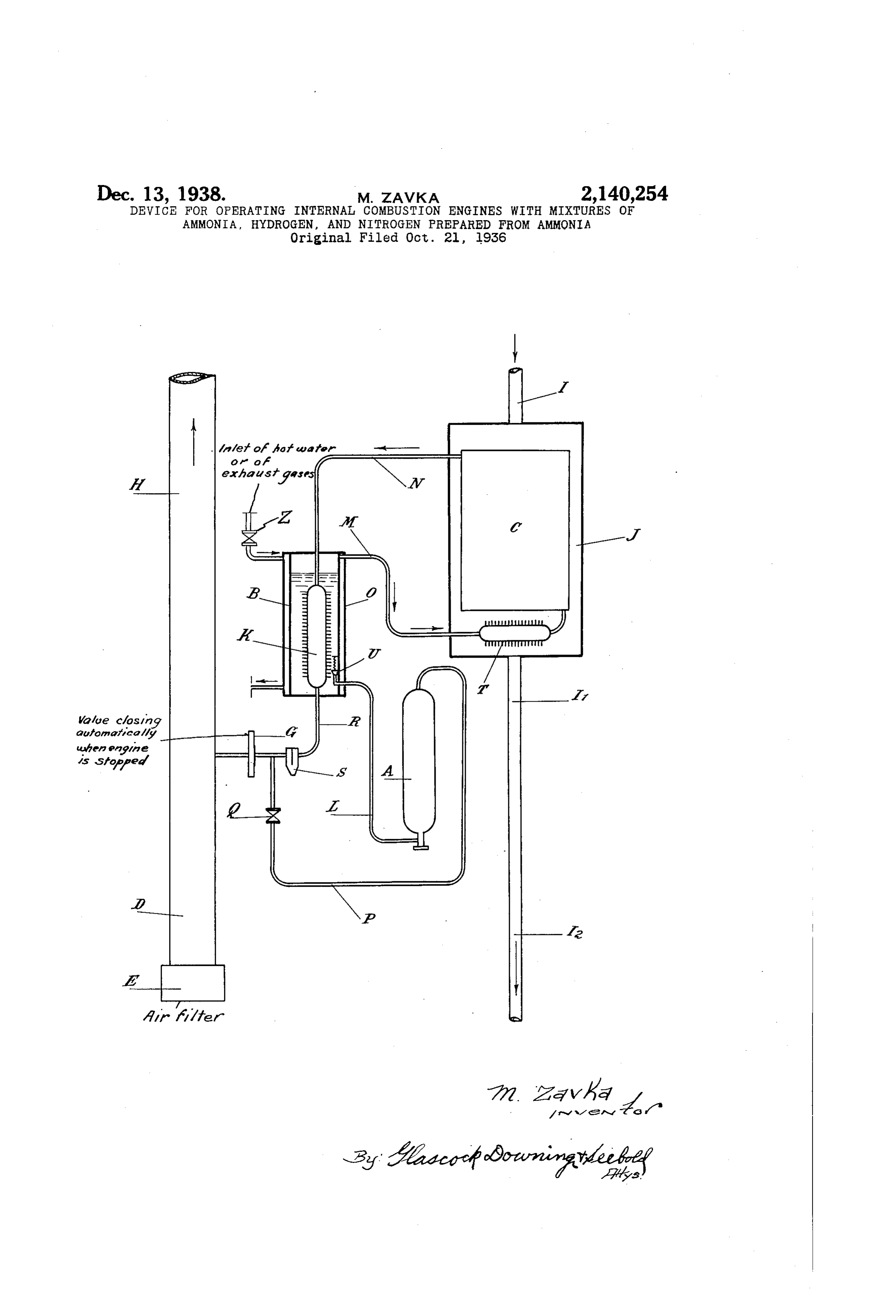
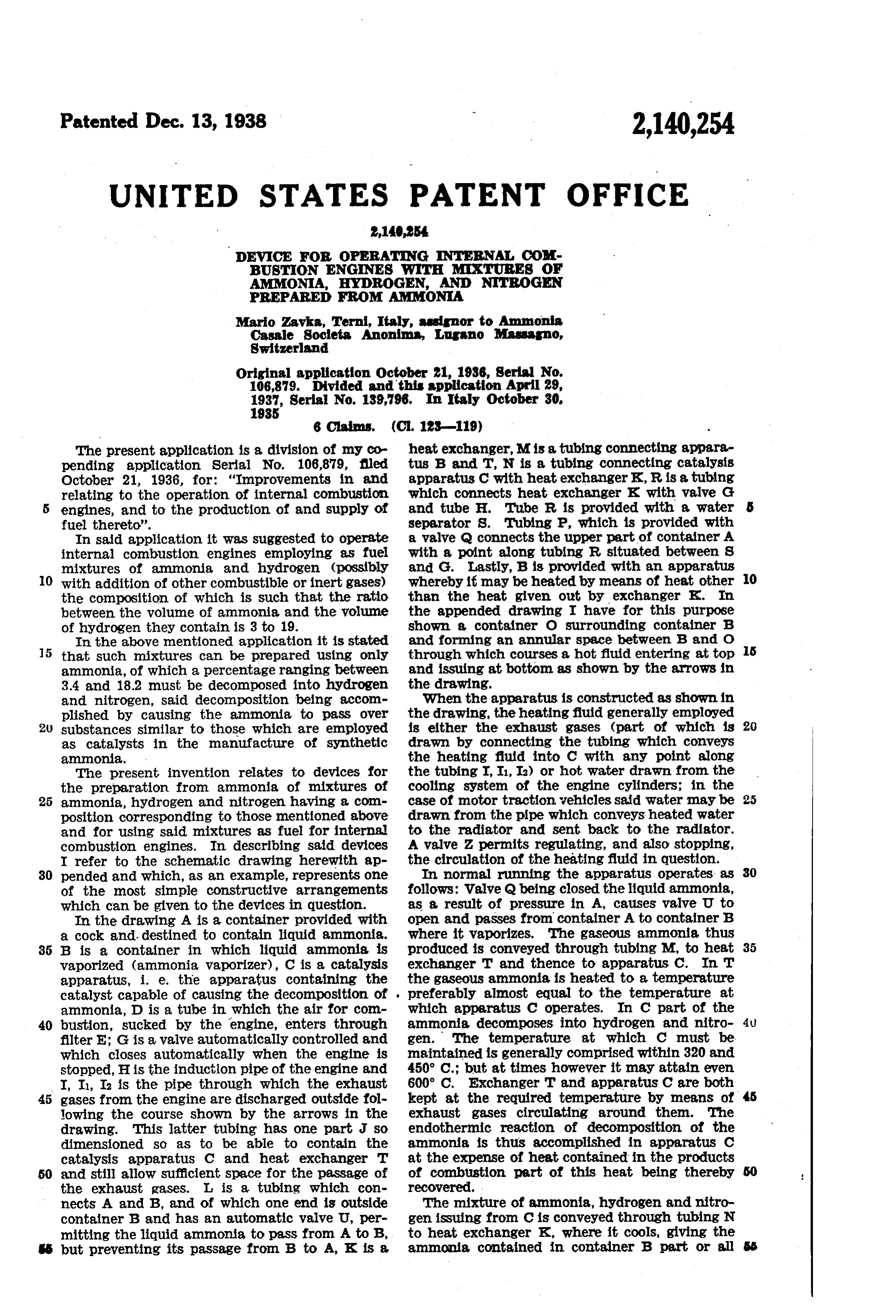
The present application is a division of my co heat exchanger, M is a tubing connecting appara pending application Serial No. 106,879, filled tus B and T, N is a tubing connecting catalysis October 21, 1936, for: "Improvements in and apparatus C with heat exchanger K, R is a tubing relating to the operation of internal combustion which connects heat exchanger K with valve G 5 engines, and to the production of and supply of and tube H. Tube R is provided with a water 5 fuel thereto'. separator S. Tubing P, which is provided with In said application it was suggested to operate a valve Q connects the upper part of container A internal combustion engines employing as fuel with a point along tubing R, situated between S mixtures of ammonia and hydrogen (possibly and G. Lastly, B is provided with an apparatus whereby it may be heated by means of heat other 10 10 with addition of other combustible or inert gases) the composition of which is such that the ratio than the heat given out by exchanger K. In between the volume of ammonia and the volume the appended drawing I have for this purpose of hydrogen they contain is 3 to 19. shown a container O surrounding container B In the above mentioned application it is stated and forming an annular space between B and O that such mixtures can be prepared using only through which courses a hot fluid entering at top 15 and issuing at bottom as shown by the arrows in ammonia, of which a percentage ranging between 3.4 and 18.2 must be decomposed into hydrogen the drawing.
and nitrogen, said decomposition being accom When the apparatus is constructed as shown in plished by causing the ammonia to pass over the drawing, the heating fluid generally employed 20 substances similar to those which are employed is either the exhaust gases (part of which is 20 as catalysts in the manufacture of synthetic drawn by connecting the tubing which conveys ammonia. the heating fluid into C with any point along The present invention relates to devices for the tubing I, I, Ia) or hot water drawn from the the preparation from ammonia of mixtures of cooling system of the engine cylinders; in the 25 ammonia, hydrogen and nitrogen having a con case of motor traction vehicles said water may be 25 position corresponding to those mentioned above drawn from the pipe which conveys heated water and for using said mixtures as fuel for internal to the radiator and sent back to the radiator. combustion engines. In describing said devices A valve 2 permits regulating, and also stopping, I refer to the schematic drawing herewith ap theIncirculation of the heating fluid in question. normal running the apparatus operates as 30 30 pended and which, as an example, represents one of the most simple constructive arrangements follows: Walve Q being closed the liquid ammonia, which can be given to the devices in question. as a result of pressure in A, causes valve U to In the drawing A is a container provided with open and passes from container A to container B a cock and destined to contain liquid ammonia. where it vaporizes. The gaseous ammonia thus 35 B is a container in which liquid ammonia is produced is conveyed through tubing M, to heat 35 vaporized (ammonia vaporizer), C is a catalysis exchanger T and thence to apparatus C. In T apparatus, i. e. the apparatus containing the the gaseous ammonia is heated to a temperature catalyst capable of causing the decomposition of preferably almost equal to the temperature at ammonia, D is a tube in which the air for com which apparatus C operates. In C part of the 40 bustion, sucked by the engine, enters through ammonia decomposes into hydrogen and nitro- 4u. filter E; G is a valve automatically controlled and gen. The temperature at which C must be which closes automatically when the engine is maintained is generally comprised within 320 and stopped, His the induction pipe of the engine and 450 C.; but at times however it may attain even I, I, I2 is the pipe through which the exhaust 600° C. Exchanger T and apparatus C are both 45 gases from the engine are discharged outside foll kept at the required temperature by means of 45 lowing the course shown by the arrows in the exhaust gases circulating around them. The drawing. This latter tubing has one part J so endothermic reaction of decomposition of the dimensioned so as to be able to contain the ammonia is thus accomplished in apparatus C catalysis apparatus C and heat exchanger T at the expense of heat contained in the products 50 and still allow sufficient space for the passage of of combustion part of this heat being thereby 50 the exhaust gases. L is a tubing which con recovered.
nects A and B, and of which one end is Outside The mixture of ammonia, hydrogen and nitro container B and has an automatic valve U, per gen issuing from C is conveyed through tubing N mitting the liquid ammonia to pass from A to B, to heat exchanger K, where it cools, giving the 5 but preventing its passage from B to A, K is a ammonia contained in container B part or all 55
Page 3
Further instead of valve U a level regulator was of the heat needed for its vaporization. (Part used, of this heat can be supplied to the ammonia by with which it was possible to keep the am apparatus O.) As a result of said cooling it is monia in container B at a constant level. Sub possible that there may be a condensation of sequently it was deemed expedient to adopt in its water in tube R. This is apt to occur particul place valve U, which in practice gives better re larly when the ammonia used is not absolutely sults and costs less than the regulator. By this sub stitution it results that if for example the quantity anhydrous, or contains dissolved oxygen, and when the catalyst in apparatus C contains Small of mixture of ammonia, hydrogen and nitrogen quantities of oxides which are slowly reduced by consumed by the engine diminishes and the pres 10 the hydrogen. Such water is separated and col sure in B consequently increases, valve U stays 10 lected by separator S and so does not reach valve closed whilst the ammonia in B continues to G. and prevent it, and thus possibly the engine, vaporize. The level of the ammonia in B from operating regularly. diminishes, part of exchanger K thus coming At its exit from S the mixture of ammonia, into contact with gaseous ammonia instead of 5 hydrogen and nitrogen passes through Valve G with liquid ammonia. The quantity of trans 5 and enters tube H where it expands to atmos mitted heat diminishes and so also the quantity pheric pressure and mixes with the air for Com of ammonia vaporized diminishes automatically bustion with which it passes to the engine. to the quantity corresponding to the consump The constructive scheme which I have de tion of the engine. The contrary happens when 20 scribed is generally followed in the case of en the quantity of mixture consumed by the engine 20 gines in which the mixture of fuel and air for increases, Lastly in certain of my experiments combustion enters the cylinders at atmospheric I provided for heating the air for combustion preSSure. with heat recovered from the exhaust gases. The same constructive scheme, with a few This method may be useful in cases where it is changes, can also be employed when the mixture desired to limit the power developed by an 25 of ammonia, hydrogen and nitrogen must be engine.
sent to the engine cylinders under a compara By means of Supplementary tubings and valves, tively high pressure, as in the case of engines of it is possible to regulate at will the quantity of the Diesel type. In this case it is obviously use hot gases circulating around apparatus T and C 30 ful that the mixture in question should have in and inside K. 30 tube R a pressure higher than that at which the The devices constructed according to the pres mixture itself must enter the cylinders, because ent invention although very simple in structure, in this way the necessity for special accessory have given excellent results in practice. In par apparatus to compress the mixture is avoided. ticular, when the engine is stopped, exchanger K. 35 To obtain a sufficient pressure for this purpose and apparatus C stay partly filled with ammo 35 it will suffice to increase the temperature at nia, hydrogen and nitrogen mixture which is used which the ammonia is caused to vaporize in B. for starting up the engine. Part of this mixture To this end recourse may be had to the auxiliary Can also be stored in the upper portion of con heating mentioned above, and which in the case tainer A, by opening valve Q after closing the 40 Of the apparatus shown in the drawing herewith cock with which A is provided. Thus the neces 40 will be accomplished with the aid of apparatus O. sity for having recourse to another fuel, for ex The pressure in R (and thus also in B, G, T) ample gasolene, in order to start the engine and in the case in point can also be considerably to bring the devices in question to the conditions higher than the vapour tension which the am required for their operation is only likely to oc monia will possess in A. This fact would make 'cur after repairs which have involved the dis 45 it impossible for the ammonia to pass from A assembling of the devices themselves. However, into B, but it can be easily remedied by causing even in such cases the engine can be started by the pressure in tubing R to rise from time to fueling it with a mixture of ammonia and air, time to much higher values than those which and it requires only a very short time to bring generally exist in said tubing. To accomplish the apparatuses to the temperature necessary for 50 this it is sufficient to heat apparatus B to a great the decomposition of ammonia to occur, where er extent so that the quantity of ammonia vapor upon the running of the engine becomes normal, izing therein, and partially decomposed in C, will Having now particularly described and ascer be greater than the quantity consumed by the tained the nature of my said invention and in 55 engines within the said time period. Operating what manner the same is to be performed, I de in this manner it is easy to cause the pressure in clare that what claim is: R. to increase rapidly. On opening valve Q the 1. Devices for fueling internal combustion en same pressure is attained in A, and once valve Q 'gines with mixtures of ammonia, hydrogen and is closed and pressure in R is returned to its nitrogen prepared from liquid ammonia com normal value, the ammonia will again be able prising in combination with the exhaust pipe and to pass from A into B. All the operations needed the induction pipe of the engine, a container for to increase the pressure in A can be accomplished liquid ammonia, an ammonia vaporizer, a tubing while the engine is running without prejudice to connecting the vaporizer with the container for its good operation. liquid ammonia, a heat exchanger placed inside 65 The operations just described can further the exhaust pipe of the engine, another tubing more be carried out whenever it is desired to in establishing communication between the heat Crease the pressure in A. exchanger and the vaporizer, a catalysis appa My invention is not to be considered limited ratus also placed inside the exhaust pipe, a tub to the constructive scheme which I have herein ing connecting the catalysis apparatus with said 70 described as an example. It is obviously pos heat exchanger, another heat exchanger placed 70 sible to give the necessary devices other forms inside the ammonia vaporizer, another tubing of structure within the limits of the present in connecting the catalysis apparatus with the last vention. mentioned heat exchanger, a further tubing con Thus during certain experiments apparatus necting the heat exchanger inside the ammonia 75 T and C were united to form a single apparatus. vaporizer with the induction pipe of the engine, 75
Page 4
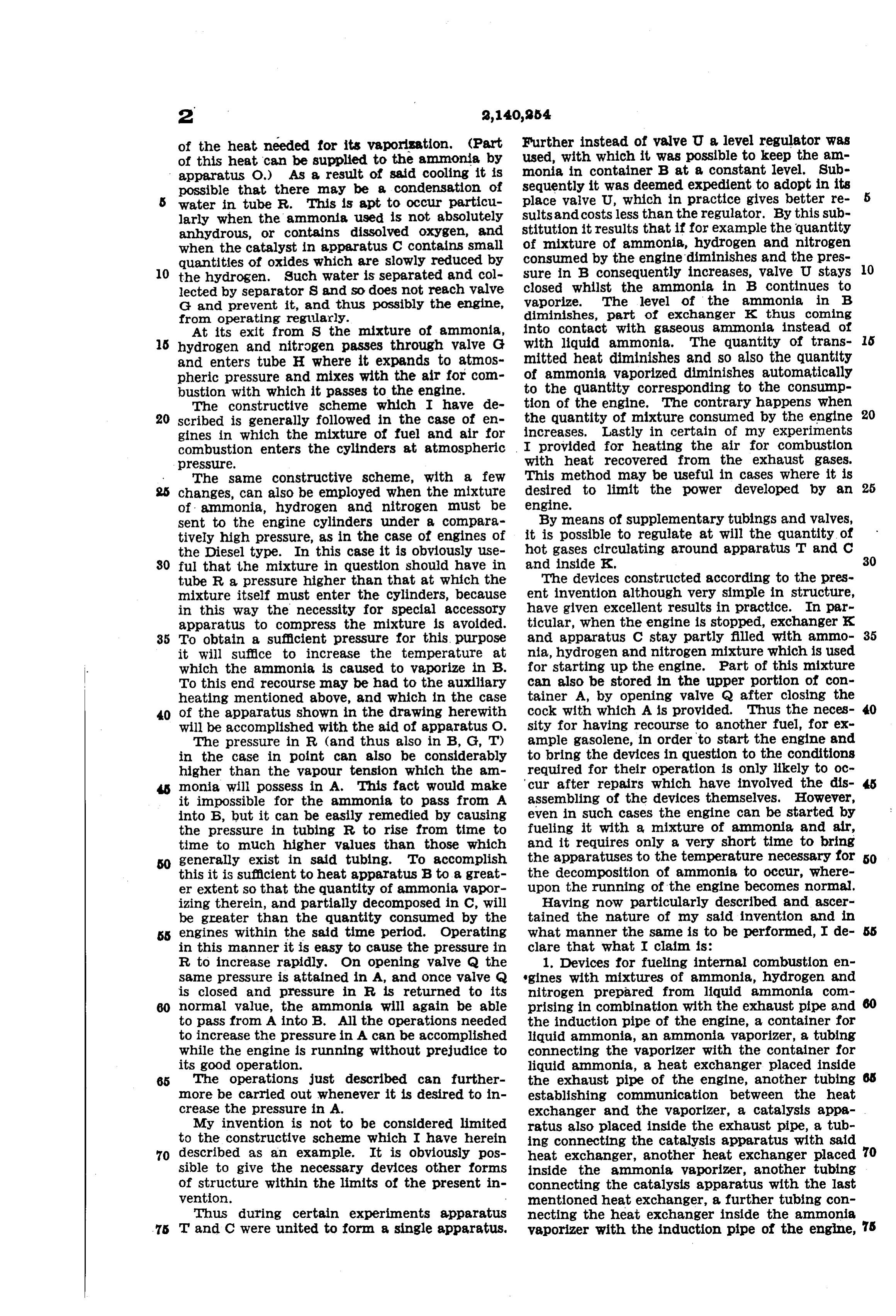
and a valve on the last mentioned tubing which 5. Device as claimed in claim 1 in which the closes automatically when the engine is stopped. tubing connecting the heat exchanger placed 2. Devices as claimed in claim i in which the inside the ammonia vaporizer with the induction tubing connecting the ammonia, vaporizer With pipe of the engine is provided with a water sepa the container of liquid ammonia is provided at arator placed before the automatically closing its end inside the ammonia vaporizer with an Valve.
automatically closing Waive preventing the pas 6. Devices as claimed in claim in which the Sage of liquid ammonia from the vaporizer to tubing connecting the heat exchanger placed the container. inside the ammonia vaporizer with the induction 3. Devices as claimed in claim in which the pipe of the engine is provided with a water sep O ammonia, vaporizer is provided with a heat ex arator placed before the automatically closing changer through which exhaust gases from the valve and a valved conduit communicating with engine are circulated. the ammonia container a point of said tubing 4. Devices as claimed in claim 1 in which the placed between the water separator and the 5 ammonia vaporizer is provided with a heat ex automatically closing valve. 15 changer through which Water employed for cool ing the engine cylinders is circulated. MARO ZAVKA.
Provenance
- Collection
- Cited prior art
- Original PDF
- patentimages.storage.googleapis.com →
- Filed
- 1937-04-29
- Pages
- 4
- Method
- pdftotext (the PDF's own text layer) + pdftoppm 300dpi page scans
- Source
- Google Patents bibliographic record
- Granted
- 1938-12-13
- Inventors
- Zavka Mario; Ammonia Casale SA
- Transcribed from
- patentimages.storage.googleapis.com →