patent · US2376479
Internal-combustion engine and combustion mixture therefor
22 May 1945
Page 1
Drawing sheet — no readable text.
Page 2
Drawing sheet — no readable text.
Page 3
Drawing sheet — no readable text.
Page 4
Drawing sheet — no readable text.
Page 5
Patented May 22, 1945 2,376.479
UNITED STATES PATENT OFFICE
NTERNAL-COMBUSTION ENGINE AND
COMBUSTION MIXTURE THEREFOR.
Hans Reinhard Fehling, London, England
Application September 30, 1942, Serial No. 460,248
In Great Britaira September 1, 1941
This invention relates to internal combustion the diatomic gases carbon monoxide and hydro engines, to methods of operating such, and to the gen instead of the normal products of combus preparation and supply of combustion compo tion of an internal combustion engine. nents for use in such engines, the invention being Further features of the invention will be here particularly concerned with the use of oxygen in after described and defined in the claims. or oxygen-enriched air in internal combustion Hereinafter in the specification the combus engines. tion according to the invention resulting in ex An object of the present invention is to increase haust products composed mainly of the diatomic the power output and thermal efficiency of in gases carbon monoxide and hydrogen will be re ternal combustion engines. A fuither object of ferred to, as may be convenient, as "substantially the invention is to provide improvements adapted incomplete combustion,' and the phrase "oxygen to make available a wider range of fuels for use or oxygen enriched air' may be conveniently en in such engines, ployed in the specification hereinafter instead of The invention further aims at providing in 5 “a liquefied gas comprising upwards of about 30% provements which jointly or severally: free oxygen.'
(a) Take advantage of the facilities afforded While the combustion agent according to the by combustion supporting agents hereinafter invention it is to be understood includes mix called 'combustion agents' derived from a lique tures in which oxygen is present in percentages fied gas as against equivalent gaseous agents as upwards of 30%, from the practical point of view subjected to compression in present-day engines, mixtures in which oxygen is present in not sub (b) Provide an improved method of combus stantially less quantities than 40% are to be tion and extraction of work from fuels by the preferred.
aid of combustion agents derived from liquid The invention may be applied to engines oper oxygen or liquid oxygen-enriched air, 25 ating on constant pressure or constant volume (c) Provide, an internal combustion engine method of combustion.
cycle adapted to the conditions imposed by the The residual combustion products of engines use of combustion agents derived from liquid operating according to the present invention for oxygen or liquid oxygen-enriched air. the operation of a secondary or subsidiary en The invention consists in a method of operat 30 gine unit or element, or for chemical or indus ing an internal combustion engine comprising trial purposes, in conjunction with combustion vaporizing a liquefied gas comprising upwards of air or oxygen in gaseous and/or liquid form, or about 30% free oxygen as a combustion agent, for use with another gas or other gases or na admitting fuel under pressure to a cylinder of terial or materials according to the purpose in the engine and admitting the vaporized combus 35 tended.
It is recognised that it has previously been pro tion agent under pressure to the engine cylinder in an amount in relation to the fuel which On posed to employ Oxygen in the actuation of in ignition effects substantially incomplete combus ternal combustion engines with a view suppos tion producing as exhaust products mainly the edly to exploiting the very high concentration of diatomic gases carbon monoxide and hydrogen 40 energy in the combustible mixture. It has been instead of the normal products of combustion of found, however, that it is neither possible nor ad an internal combustion engine. vantageous according to prior proposals to oper ate an engine with such a mixture owing to the
The invention also consists in a method of op extremely high temperatures, to the thermal erating an internal combustion engine compris ing vaporizing a liquefied gas comprising upwards 45 properties of the working fluid (containing main ly the triatomic gases, carbon dioxide and water of about 30% free oxygen for use as a combustion vapour) and to the high degree of dissociation agent, admitting fuel under pressure to a cylinder which occurs at combustion temperatures. The of the engine and admitting the vaporized com complete combustion or explosion of iduid fuel bustion agent under pressure to the engine cylin der when the piston is close to the inner end of 5) with pure oxygen produces temperatures well over 3,500. C. Upwards of 40% of the carbon dioxide its stroke in a cycle consisting of alternating and 10% of the steam are dissociated at this tem power and exhaust strokes, the combustion agent perature and at a maximum combustion pressure being admitted in amounts in relation to the fuel of about 1,000 lbs. per sq. in. For lower pres which on ignition effect substantially incomplete combustion producing as exhaust products mainly 55 Sures the dissociation is still higher, and it varies a little according to the kind of fuel used. The
Page 6
thermal efficiency of oxygen-operated engines ture would be of the same order as in the present hitherto proposed is much lower at the same ex day engines using air, the expansion tempera pansion ratios than with air as used in the Ordi tures, which are the real criterion for the ther nary way. In the present-day gasoline engine mal stress imposed upon the engines, are much the thermal efficiency (excluding wall losses) is lower. The present-day Diesel engine with a about 45% for an expansion ratio of 7:1 at cor compression ratio of 12:1 has at full power an rect mixture strength, i. e., for complete com expansion temperature of about 1,400 C. The bustion. Under the same combustion conditions, improved engine, operated with oxygen and sub but using oxygen the efficiency would be not more stantially incomplete combustion, has an expan than 22%. Needless to say that apart from the O Sion temperature of about 1,100° C. for an ex bad efficiency such an engine would be unwork pansion. of 10:1 and of about 850° C. for an ex able because of the extreme temperatures obtain pansion of 20:1. All these temperatures take into ing in it. Even at very much higher expansion account the real properties of the working sub ratios the thermal efficiencies will hardly sur stance but not the heat losses through cylinder pass the efficiencies hitherto obtained with ordi 15 Walls which vary according to the size, and type nary air. For the same reason, the maximum of engine. Compared with the present-day gaso power Output obtainable without overheating line engine the drop in temperature is even more will not be higher in oxygen-operated engines as pronounced. It Will also be appreciated that the hitherto proposed but will be lower than in en consumption of oxygen will be lessened and this, gines operated with air used in the established 20 together with the high expansion ratios that can manner. be obtained in the improved engine, will under It has also been previously proposed in engines appropriate conditions decrease the consump such as those used for propelling submarines tion of the fuel mixture below the consumption which carry a supporter of combustion (such as figures hitherto achieved for the same perform liquid oxygen) as well as a combustible fuel, to 25 ance.
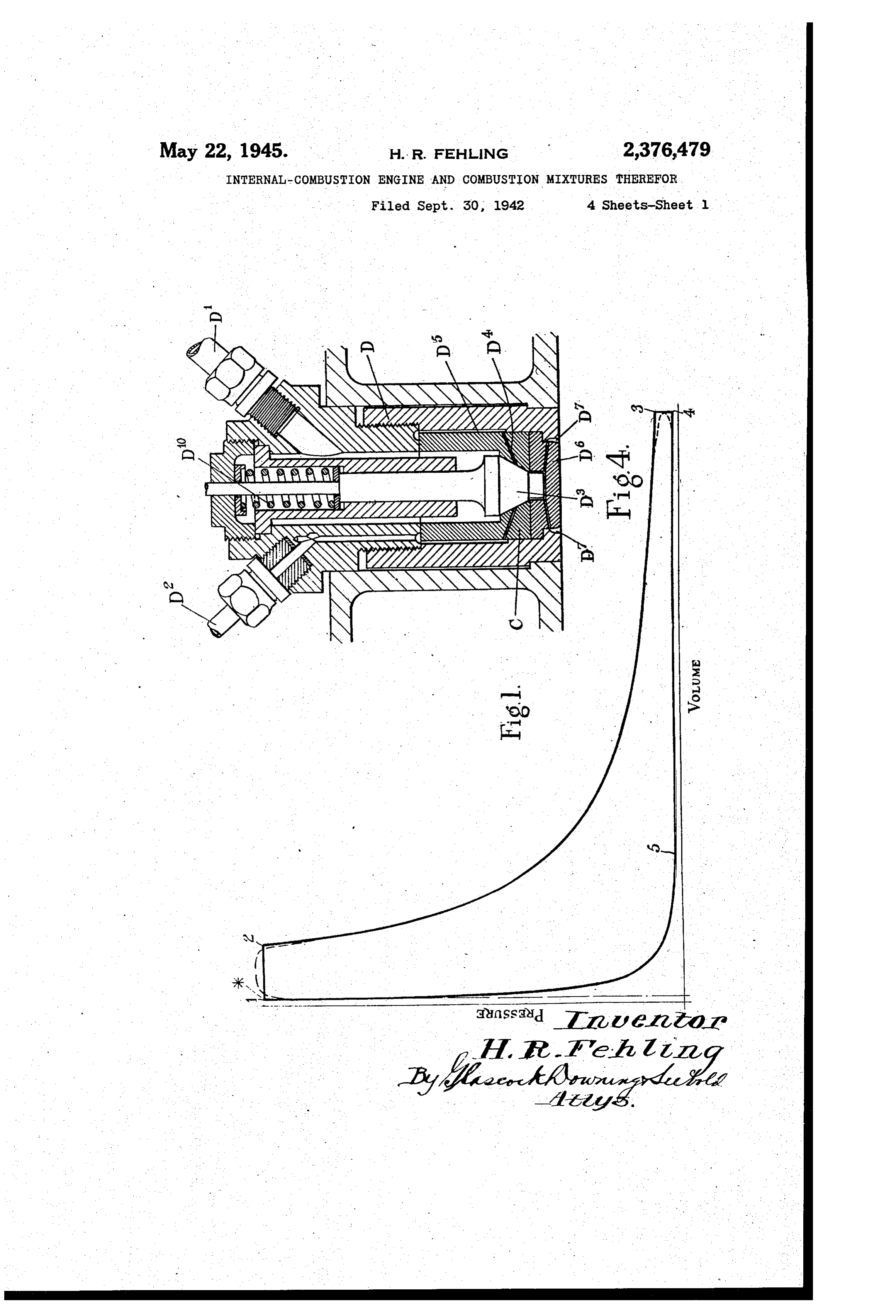
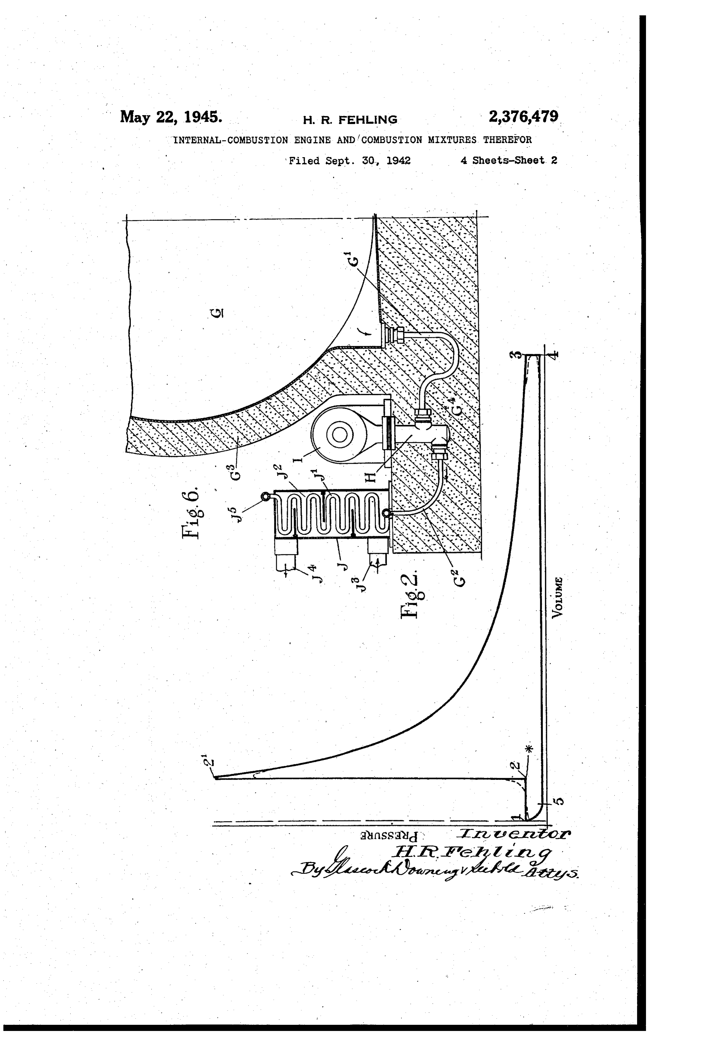
control the consumption of the supporter of con The substantially incomplete combustion of bustion so that an excess of combustible fuel is fuel and the exhaustion of unburnt gases do not supplied sufficient to secure complete consump result in waste, as the residual gases are avail tion of the oxygen, in order to economise the able for employment in performing useful work. Oxygen Supply. In order to avoid the difficulties 30 Figure 1 is a diagram of the pressure volume of high temperatures inherent to the use of oxy cycle of a constant pressure type engine accord gen it was proposed to dilute the oxygen and fuel ing to the invention, while mixture with a proportion of the products of Figure 2 is a diagram of the pressure volume combustion. In this case it will be appreciated Cycle of a constant Volume type engine accord that the object of the proposed richer mixture 5 ling to the invention.
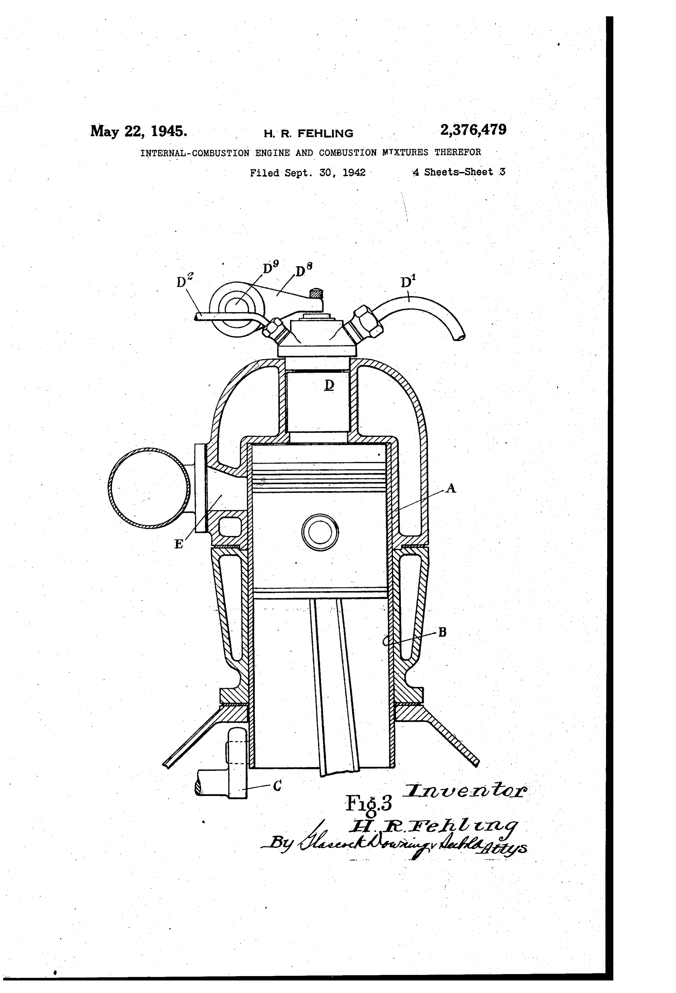
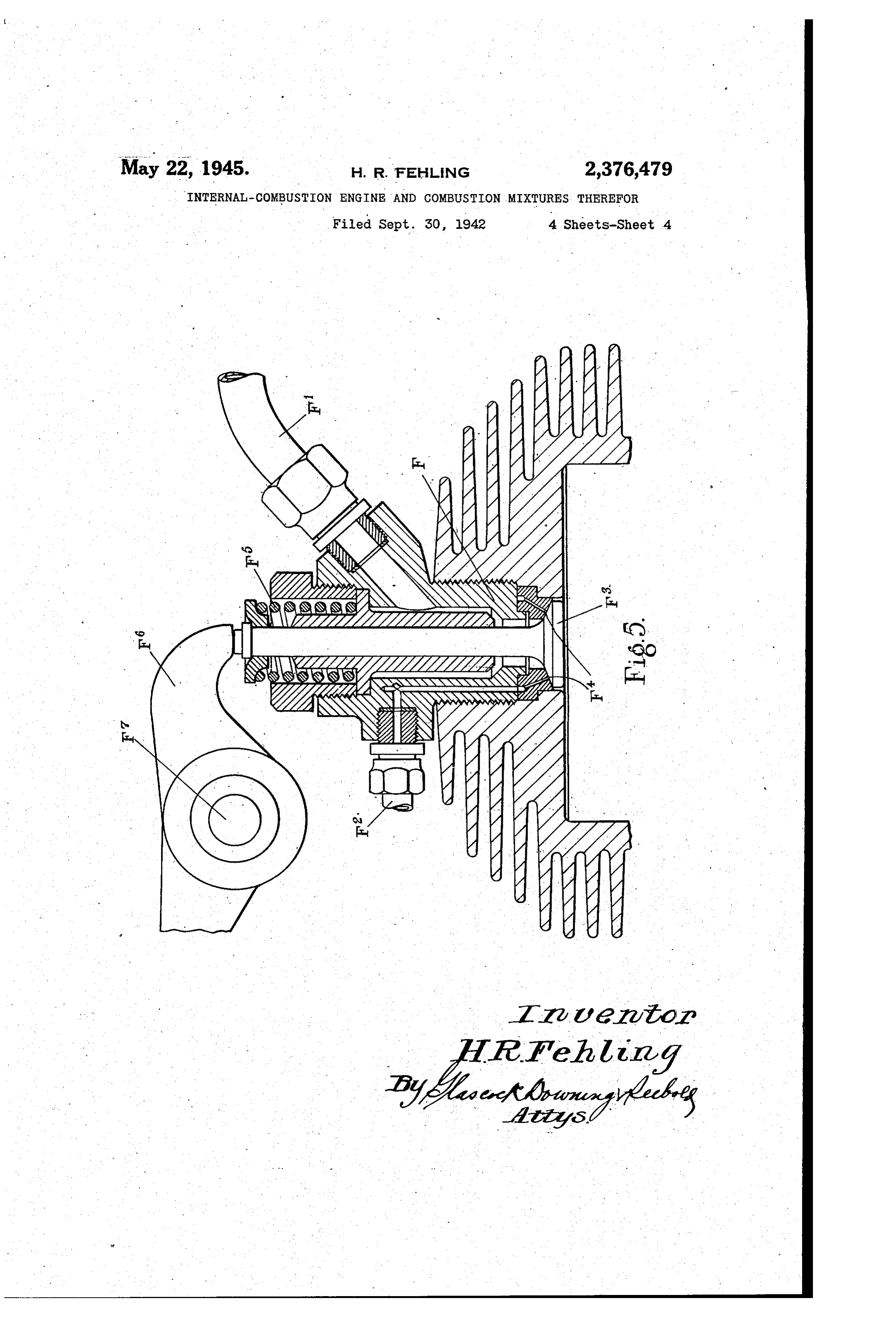
was to conserve the limited oxygen supply and Figure 3 is a part sectional elevation of an was not directed, as is the present invention, to engine showing the piston and cylinder designed a control calculated (inter alia) to produce Serv to exemplify the improved cycle. iceable lower combustion temperatures by effect Figure 4 is a sectional elevation of the injector ing substantially incomplete combustion as here f nozzle device indicated in external elevation at in defined. the outer end of the cylinder in Figure 3. According to the present invention it is pro Figure 5 is a cross section of the head and outer posed to circumvent the above difficulties attend end of a cylinder of an engine for operating upon ant upon the use of oxygen, by the deliberate pro 45 the constant volume method according to the in vention, and illustrating an appropriate type of hibition of the substantially complete combustion of the fuel content of the combustible mixture as injection valve arrangement, and referred to above by supplying only a fraction Figure 6 is a sectional view diagrammatically of the oxygen needed for the combustion conver illustrating part of a reservoir, a compression sion of the fuel to carbon dioxide and water pump and a heat exchange coil for Supplying vapour. The burnt mixture, as indicated earlier, vaporized combustion agent. thus contains mainly the diatomic gases, car In carrying the invention into effect the com bon monoxide and hydrogen (H2), with or with bustion agent is made available in the liquid state out nitrogen, which represent very good working either by liquefying the agent in a plant associ substances mainly by virtue of their low specific ated with the engines in which the agent is to be heat. The reduced range of temperatures 55 used or by using such from Suitably insulated achieved by adopting the incomplete combus storage containers.
tion method, also ensures that dissociation is The liquid agent is vaporized by pumping Such eliminated or reduced to a minimum. As a con into a vaporizer maintained at a predetermined sequence of the above procedure by far the pressure (or pressure range) and at an appropri greater part of the heat generated by combus ate temperature (or temperature range). tion is available for conversion into useful work. In the case of the constant pressure method of At an expansion ratio of 10:1, corresponding to combustion the vaporizer pressure is equal to (or a very high power output, about 60% of the heat in view of pressure losses on the Way) slightly generated is converted into work. For normal higher than, the maximum cylinder pressure at power the expansion ratio would be increased, (6.5 which the engine is designed to work. This pres for example, to 20:1 by earlier closing of the in sure may, vary between 600 and 1,000 lbs. per sq. in, and is determined according to considerations let valve or nozzle, and the efficiency would rise of weight and type of engine Such as are fami- i. to 70%. Under idling conditions it would be pos liar to those skilled in the art. sible to expand a very small charge by as much Should it be required to regulate the engine as 50:1 and in this case the efficiency would be power over 80%. The improved engine is cooler than en it mayby varying the maximum cylinder pressure gines using ordinary air at the same expansion "pressurebeconstant found convenient to keep the vaporizer ratio and affords a much higher power output than, the critical atpressure) high level (e.g., at, or higher and to throttle the per swept cylinder volume.
While the combustion or explosion tempera 75 oxygen before entry into the cylinder. However,
Page 7
the vaporizer pressure must under all circum be reduced to less than is inch (measured axially) stances be at least equal to the maximum cylin while in larger engine cylinders it might be more der pressure. When using the constant pres than 6 inch. As a rule it will be possible to sure method of combustion the liquid agent is bring down the unswept cylinder volume at top vaporized at critical or super-critical pressures, dead centre to 1% of the total cylinder Volume. for example liquid oxygen may be pumped into This is, however, only required where it is in the vaporizer at a pressure of about 750 lbs. per tended to make use of extremely high expansion sq. inch or more, such that the transfer from ratios of, say, 50:1 and more. Where, however, the liquid into the gaseous state is continuous the expansion ratio is not to exceed 30:1 even at without any break or interface between the low loads, there is no necessity for a clearance phases. Volume of less than 2 per cent. When the liquid agent is produced in a plan The combustion of the mixture during the associated with the engine the cold content of power stroke, according to the constant pres the liquid pumped into the vaporizer, as well as Sure method conditions, is arranged So that the part of the power subsequently generated, may 5 fuel ignites as soon as it enters the cylinder and advantageously be used in the production of burns continuously at about constant pressure fresh liquid agent. For example, quantities of without the cylinder being filled at any moment the agent in gaseous form may be caused to paSS with any appreciable amount of unignited Com in heat transference relationship with the liq uid agent during vaporization and utilised to pro 20 bustible mixture.
In Figure is a theoretical pressure/volume dia vide desirable temperature conditions while the gram is shown of an example of the improved cooled gaseous agent is subsequently supplied to cycle for a constant pressure type engine, the the liquefying pressure plant, which Inay be full lines indicating the ideal form while the dot driven or in part driven by power supplied from ted lines give an approximation to an indicator the engine (or engines) to which the vaporized diagram form.
combustion agent or its products are supplied. Ignition is indicated by the asterisk. Points The appropriate temperature for the combus -2 cover the period of substantially constant tion agent will be mainly governed by the kind pressure. At 2 the inlet is cut off and from 2-3 r of fuel used. in the case of gasoline which ig expansion and power stroke proceeds. Exhaust . nites easily the temperature need not be higher 30 takes place from 4-5, the exhaust valve closing than that of the surroundings. With heavier fuel at 5, while from 5 to recompression of exhaust it will be more convenient to increase the ten gas is effected.
perature to 100° C. or more. Only in the case In the constant volume method the condi where the ignition itself is to be effected by con tions of the combustion agent aire So adjusted tact with the hot combustion agent as referred 35 that the temperature and pressure at entry are to hereinafter, is it requisite that the agent such as to prohibit ignition of the fuel before the should be preheated to upwards of 350° C., de inlet valve has closed and the desired crank angle pending on the kind of fuel. . has been reached. The charge is fired by Spark The vaporized combustion agent is supplied ignition at the appropriate moment and combus from the vaporizer under pressure to the internal 40 tion proceeds at about constant volume in much combustion engine through a suitable valve or the same way as in the present-day gasoline or injection nozzle device. Where admission is ef gas engine with spark ignition. fected through a valve any suitable known form Figure 2 shows a theoretical pressure/volume of valve may be employed but it is preferred to diagram of an example of the improved cycle for employ a valve of the sleeve-valve type. Where 45 a constant volume type engine. As in Figure a nozzle is employed it is preferred to employ one the full lines illustrate the ideal curve while the of the type in which the injection valve is con dotted lines give an approximation to an indicator trolled mechanically. diagram form.
The fuel is injected at the same time as the Ignition is indicated by the asterisk. At the entry of the combustion agent and may be either 50 inlet valve opens. From to 2 the cylinder re in liquid form or vaporized under pressure in a ceives the combustible mixture. From 2-2' the vaporizer and supplied to the cylinder through a explosion pressure rise is shown. Expansion and suitable valve or nozzle. There may be cases, as , power stroke is represented from 2'-3. The ex for example with engines running on heavy fuels haust stroke proceeds from 4-5, while from 5-f or at high speeds, when it may be advantageous 5 5 there is recompression of residual exhaust prod to allow the mixture of fuel and combustion luctS.
agent to be effected immediately before entering According to both the constant pressure and the clearance between the piston and the Cylin constant volume methods of operation the charge der head. On the other hand, separate inlets weight supplied to the engine is controlled by the for the fuel and the combustion agent may be 60 thermodynamic state of the combustion agent provided and so arranged that a reliable and entering the cylinder and/or by timing the oper complete mixture or combustion relationship is ation of the inlet valve or nozzle. effected at the point of entry in the combustion In an engine operating according to the con clearance. stant volume method the pressure and temper As the preferred engine is devised to operate ature of the non-ignited charge are so adjusted on the improved cycle comprising power strokes that the charge weight per cycle is correct for the alternating with exhaust strokes the combustion power required, and that the explosion pressure chamber proper, such as is found in present-day does not exceed the pressure limit for which the engines, is absent and substituted by a clearance 70 engine is designed. If, for example, the engine is sufficient for operating according to the cycle and built for a maximum cylinder pressure of ,000 the conditions described below. lbs. per sq. inch the charge pressure P lb./sq. in. It is obvious that for mechanical reasons there and its temperature TC. absolute, have to be so must be a certain clearance between piston crown adjusted that P/T=0.11 to 0.14. and cylinder head. In small engines manufac 75 In the case of gasoline, for example, the tem tured with great precision, this clearance might perature of the ingoing charge may be 20° C.
Page 8
and its pressure would have to be equal to, or less As indicated the piston clearance may be em than, 40 lbs./sq. in. If the highest permissible ployed for the compression of part of the residual cylinder pressure is less than 1,000 lbs. the above exhaust (see indicator diagrams Figures 1 and 2) P/T-ratio is to be decreased in proportion. to prevent a sudden pressure rise. It will be After ignition the combustion gases expand appreciated that the degree to which the exhaust throughout the power stroke and at the termina should be recompressed for this purpose depends tion thereof the exhaust port opens and on the on the size of engine, its speed, and particularly return stroke the piston scavenges the cylinder to the distribution of inertia forces exercising and pushes out the exhaust gases through the upon the reciprocating parts near the top dead exhaust port. O centre. However, as a general guide the follow It will be appreciated that although the en ing figures may be given:
gine operates on a two-stroke cycle it does not The exhaust valve is to close when the piston function according to the known two-stroke cycle has reached a point where the residual volume as there is no induction stroke or Scavenging is a times the clearance volume at top dead of the exhaust by the inlet gases. centre
By virtue of the power-exhaust stroke cycle For the constant pressure cycle ac=15 to 25 the expansion ratio for the engine is completely For the constant volume cycle ac=2 to 4 independent of the usual compression ratio and of the state of the charge or conditions of the With a clearance volume of 1 per cent, the cylinder prior to ignition. The expansion ratio exhaust valve is therefore to close can be varied as required in the design of the engine from very low ratios for the production At 40 to 50 degrees of crank angle before top of high power output tip to very high ratios dead centre for the constant pressure cycle; employing Small charges in Order to provide con At 15 to 20 degrees of crank angle before top ditions of maximum thermal efficiency. dead centre for the constant volume cycle.
Owing to the fact that, with the constant The advantages of compressing a residual pressure method, the cylinder is not filled at any charge would be to prevent a Sudden pressure moment with any appreciable amount of non rise at the top dead centre when the inlet opens ignited combustible mixture, any kind of det and to avoid the mechanical defects arising from onation or sudden pressure rise is prevented and 30 fluctuations, of maximum pressure which might the pressure and temperature of the entering otherwise be met. At the same time the process charge can be so chosen as best to suit the par of ignition (in the constant pressure method) of ticular fuel employed, taking into consideration the entering charge close to the inlet is greatly its chemical reactivity and its thermal proper facilitated as in the first place the temperature ties etc. With the constant volume method diet of the residual exhaust is very much increased onation can be prevented without sacrificing by compression, for example it may be in the the advantages of a high expansion ratio by neighbourhood of 1,200-1,400° C., thus affording controlling pressures and temperatures of the a means of assisting in ignition of the charge charge. at the moment of entry. Furthermore, if there. It has already been mentioned above that in 40 were the full pressure difference between vapor the case of the constant volume cycle a certain izer and exhaust pressure at the point of entry pressure-temperature ratio has to be maintained, of the charge when the inlet opens, the charge and that for a maximum cylinder pressure of would blow into the cylinder at very great veloc 1,000 lbs. this ratio was of the order of 0.11 ity and probably would not ignite at the point to 0.14. It is, therefore, possible to keep the ra 43 of entry. The delayed ignition would then lead tio within the prescribed limits by using low to a sudden explosion with all the unsatisfactory temperatures and pressures of, for example, 0 Consequences arising therefrom. C. and 35 lbs. in order, to prevent pre-ignition Another method of effecting or assisting igni and detonation. tion, which may be used in connection with or As indicated; the cycle and method of intro 50 independently of the method just described of duction of the charge make a combustion cham compressing a residual charge, is to preheat the ber as such unnecessary. The provisiona of such combustion agent to a temperature sufficient to chamber would, on the contrary, reduce the max ensure immediate ignition when the agent is imum expansion ratio which would be otherwise brought into contact with the fuel, although it obtainable. For practical reasons, however, 65 is thought that this will be effected in any case there will always be a small volume unswept by without preheating of the agent at or before the piston when such arrives at the top dead entry.
centre. A further method of ignition applicable to the The volume or clearance left between the pis constant pressure cycle, is to arrange the inlet ton Crown and the cylinder may be employed for 00 of fuel and combustion agent in such a position the compression of a proportion of the residual that they come into contact with a hot spot or exhaust gases at the end of the exhaust stroke Surface. W by, for example, closing the exhaust port at a The choice of combustion agent, that is to say predetermined crank angle before top dead cen whether pure oxygen or oxygen-enriched air is tre. If, for example, the pressure of the residual s used, will depend on the purposes for which the exhaust by the above compression method is engine is intended. In cases where the agent is raised to or nearly to the pressure of the vapor not produced in connection with the power plant ized combustion agent, there would be no or only but supplied to it from containers or reservoirs, it a little difference in pressure between the vapor may be found advantageous to use pure or nearly izer pressure and that in the cylinder when the 70 pure oxygen in order to save weight. inlet opens. Consequently, the amount of com The accompanying drawings, Figures 3-5, are bustion agent entering the cylinder would in this intended to exemplify the improved cycle and case be governed entirely by the volume swept method, and indicate arrangements for carrying by the piston between the opening and closing the invention into effect without attempting to of the inlet. s illustrate any hard and fast design. Figure 3 is
Page 9
a cross-sectional elevation of the cylinder and It will be appreciated that according to the sub a fragment of the crankcase of an engine of the staatially incomplete combustion method the re constant pressure type for operating upon the sidual unburnt gases (i.e., mainly diatomic gases) power-exhaust stroke cycle according to the in possess a valuable capacity for doing further vention. The cylinder A is fitted with a sleeve 5 work. Accordingly it is proposed to employ the valve B which is given an operational displace exhaust products as the notive power in a sec ment such that a point thereon moves in an el ondary or supplementary engine unit or element liptical path, motion being communicated by the or for industrial or chemical purposes. The gas crank C. driven by any suitable gearing at the eous exhaust fuel from the primary engine may same speed as the crankshaft. In the cylinder O be used in suitable burners for the generation of head an injection nozzle device D of any suit steam in any of the known types of gas-fired able known type is provided, an example of steam generators, or it may be used as a fuel for which is shown in cross section in Figure 4. a second internal combustion engine, such as a Vaporized combustion agent enters the device by gas engine or compression ignition engine, or for the pipe D while the fuel is introduced through 5 acting upon a trunk piston arrangement in the the pipe D. An inlet injection valve D3 con primary engine, or in a supplementary cylinder trols the emission of the combustion agent and in the primary engine block.
fuel, the latter being admitted to the valve seat In employing a gas engine as the secondary en through ducts D which communicate with the gine the exhaust from the primary engine is em supply at D through clearance D5. An atomiser 20 ployed as combustion fuel for the gas engine. plate D is provided across the valve opening and The exhaust gases from the primary engine, al positioned to afford an annular clearance D though cooler than the exhaust gases from nor where ignition takes place. The valve is me mal internal combustion engines, may be still chanically operated by a lever D9 of a rock shaft further cooled by any known means before use in D9 against the action of spring D10. The exhaust the gas engine. As the exhaust products from the port in the cylinder is seen at E while the corre primary engine will always be at a pressure higher sponding port in the sleeve B is not shown in the than atmospheric pressure, it is possible to super section as it is turned into an out-of-register po charge the gas engine cylinder by means of such sition to close the exhaust port as the piston in higher pressure exhaust gases and to utilise the this view is shown at the beginning of its power 30 Waste power of the primary engine in this way stroke position. . . to increase the power output of the secondary en Figure 5 is a cross section of the head and gine. According to one method of accomplish upper end of a cylinder of an engine for operat ing this effect lower pressure atmospheric air is ing upon the constant volume method according aspirated first and the higher pressure gas from to the invention showing an appropriate type of the primary engine is admitted towards the end of . injection valve arrangement. the induction stroke. An adequate mixture of gas The constant volume engine may have a sleeve and air may be effected by the aid of known tur valve for controlling the exhaust port which may bulent methods during part of the induction and be located in a similar position to the port E seen the whole of the compression stroke. in Figure 3 or any suitable form of exhaust valve According to another method, the higher pres "may be employed. An air-cooled cylinder may Sure-exhaust products may be employed to induce be provided or the cylinder may be water-cooled in a known manner the lower pressure atmos as illustrated in Figure 3. pheric air, thus obtaining a mixture of super-at In Figure 5 the combustion agent enters the mospheric pressure in delivering the combustion injection valve device F through the pipe F1 and mixture to the engine.
the fuel passed into the device through the pipe The exhaust gases from the primary engine F2. The valve F3 controls fuel ducts F4 in the may be used in a secondary engine of the com valve seat and the emission of the combustion pression-ignition type operating on the four- or agent. The valve is operated against the action two-stroke cycle. In a four-stroke engine the of a compression spring F5 by a tappet F on a 50 exhaust, products of the primary engine may be rock shaft F. The spark plug for igniting the admitted during the induction stroke (without charges may be located in the cylinder head or addition of combustion air). The exhaust fuel is in the cylinder wall adjacent the head but is not compressed on the compression stroke and to shown in the drawings. Wards the end of this stroke oxygen or oxygen In Figure 6 is diagrammatically illustrated in 55 enriched air generated from a liquid source in a fragmentary cross section a vaporizer plant Similar manner to that described above is utilised adapted for the supply of vaporized combustion as the combustion agent, being injected into the agent. A reservoir G for liquid oxygen or oxy hot and compressed gas, which is thereby ignited, gen-enriched air Supplies the liquid agent to the the ratio of the exhaust gas and the combustion cylinder of a compression pump H through a 60 agent being so adjusted that substantially incom pipe C, the drive for the pump being indicated plete combustion takes place. If it is desired to at I. The pump forces the liquid agent through reduce the consumption of oxygen mixture a cer the pipe G into a suitable vaporizer shown in tain amount of air may be admitted during the conventional form at J. - induction stroke and compressed with the ex The liquid agent reservoir covered by insula 65 haust gases by making use of one of the methods tion G and the pipes G and G2 as well as the above described in connection with the gas engine. pump H are embedded in insulating material G4. In this case, however, the amount of air admitted The heat exchange coil or element Ji is sur is such that no ignition can occur before the rounded by a heating jacket J through which is oxygen mixture is injected into the cylinder and circulated a heating agent via the pipe connec 70 that complete combustion will not take place.
Vaporized agent at a predetermined pressure may The exhaust products of the primary engine and temperature leaves the coil at J5 and passes also be employed in a secondary engine oper ating on the ordinary two-stroke cycle, when the to engine inlet pipes such as D, F (Figures 3 and exhaust from the primary engine, being at higher 5), for admission through the injection valve, s pressure than atmospheric, may be used towards
Page 10
the end of the power stroke for induction and agent being admitted under pressure and temper scavenging purposes. ature conditions such that ignition takes place This application of the invention is based on on injection, the ordinary compression ignition four- and two 3. In internal combustion engine operation, stroke cycle as a model, i. e., insofar as the suc vaporizing a liquefied gas comprising upwards of cession of strokes is concerned, but the parts about 30% free oxygen as a combustion agent, played by the fuel and the combustion air are re admitting fuel under pressure to a cylinder of versed, the latter and not the fuel being derived the engine and admitting the vaporized combus from a liquid source and injected into the fuel tion agent under pressure to the engine cylinder which is gaseous and is compressed. Otherwise, in an amount in relation to the fuel which on the known methods of operation developed for . ignition effects substantially incomplete combus the Diesel engine may be applied and known types tion producing as exhaust products mainly the of valve arrangement, injection nozzle and means diatomic gases carbon monoxide and hydrogen of creating turbulence in the cylinder may be instead of the normal products of combustion employed. of an internal combustion engine, the said fuel The only differences that require mention are and agent being admitted under pressure and that the combustion agent will be preferably in temperature conditions such that ignition does jected (into the fuel) in the gaseous state after not take place on injection but is effected by an having been vaporized under pressure, and that applied spark.
it is practicable to admit part of the oxygen re 20 4. In internal combustion engine operation, quired by mixing atmospheric air (the balance of vaporizing a liquefied gas comprising upwards of oxygen being derived from a liquid source as in about 30% free oxygen for use as a combustion dicated) with the gaseous fuel before compres agent, admitting fuel under pressure to a cylinder S10. of the engine and admitting the vaporized com The pressure in the vaporizer has to be higher 25 bustion agent under pressure to the engine cyl than the pressure of the gas at the end of the inder when the piston towards the end of its compression stroke. The temperature of the stroke is close to the cylinder head in a cycle combustion agent may be 50 to 150° C. consisting of alternating power and exhaust The amount of combustion agent which can be strokes, the combustion agent being admitted in admitted before, the compression stroke without 30 amounts in relation to the fuel which on ignition danger of preignition obviously depends on the effect substantially incomplete combustion pro . inflammability of the gaseous fuel used. For ex ducing as exhaust products mainly the diatomic ample, if the exhaust gas from the primary en gases carbon monoxide and hydrogen instead of gine consisting of carbon monoxide and hydro the normal products of combustion of an internal gen is used, a charge containing up to 20% of air 35 Combustion engine.
and 80% of gas may be compressed. After in 5. In internal combustion engine operation as jecting oxygen a combustion gas may be obtained claimed in claim 4, closing the exhaust port at a containing about 33% carbon dioxide and steam, predetermined angle before top dead centre to and 67% diatomic gases, at about the same com recompress a part of the diatomic exhaust pro bustion temperature as in the present-day en 40 ducts to effect the ignition of the incoming fresh gine. In this particular case 28% of the oxygen charge of fuel and vaporized combustion agent. would be supplied as air. 6. In internal combustion engine operation. It will be appreciated that instead of employ ing exhaust products from the primary engine 45 intoclaimed as in claim 1, admitting gaseous fuel a cylinder of the engine and injecting the equivalent gases (as for example water gas, town vaporized combustion agent towards the end of gas, coke oven gas, and natural or oil gas) from the compression stroke of a four-stroke engine industrial or other sources may be employed in cycle.
conjunction with injected oxygen or oxygen-en 7. In internal combustion engine operation as riched air generated from the liquid source in the claimed in claim . and according to the ordi manner above indicated. nary two-stroke cycle, admitting gaseous fuel into I claim: a cylinder of the engine towards the end of the 1. In internal combustion engine operation, power stroke thereby expelling the combustion vaporizing a liquefied gas comprising upwards of products, compressing the gaseous fuel on the about 30% free oxygen as a combustion agent, following instroke and injecting the vaporized admitting fuel under pressure to a cylinder of the combustion agent towards the end of compres engine and admitting the vaporized combustion ision in the two-stroke cycle.
agent under pressure to the engine cylinder in an 8. The operation of an internal combustion amount in relation to the fuel which on igni engine as claimed in claim 1 and according to tion effects substantially incomplete combustion . 60 the four-stroke cycle wherein gaseous fuel com producing as exhaust products mainly the dia prising industrial gases is admitted during the tomic gases carbon monoxide and hydrogen in suction stroke and the said vaporized combustion stead of the normal products of combustion of agent is injected in the amount specified in the internal combustion engine. said claim, towards the end of the compression 2. In internal combustion engine operation, stroke..
vaporizing a liquefied gas comprising upwards of 65 9. The operation of an internal combustion about 30% free oxygen as a combustion agent, admitting fuel under pressure to a cylinder of the , engine as claimed in claim 1 and according to the ordinary two-stroke cycle wherein gaseous engine and admitting the vaporized combustion fuel agent under pressure to the engine cylinder in 70 wardscomprising the end industrial gases is admitted to of the power stroke and the said an amount in relation to the fuel which on igni vaporized combustion agent is injected in the tion effects substantially incomplete combustion producing as exhaust products mainly the dia amount end of specified in the said claim, towards the compression.
tomic gases carbon monoxide and hydrogen in 10. An internal combustion engine installation stead of the normal products of combustion of an internal combustion engine, the said fuel and 75 having a vaporizer for liquefied gas comprising
Page 11
upwards of about 30% free oxygen for use as a cated to admit the said fuel and the said agent combustion agent in the engine, a pump deliver to the cylinder head end of the cylinder and ing the liquefied gas to the vaporizer under the cylinder has its exhaust valve located towards pressure, means for admitting fuel and admit the cylinder head-end of the cylinder and where ting vaporized agent under pressure to a cylinder 5 in actuating heans are provided for operating of the engine in relative amounts which on igni the said inlet means and said exhaust valve on tion effect substantially incomplete combustion a two-stroke cycle consisting of alternating pow producing as exhaust products mainly the di er and exhaust strokes, the inlet taking place atomic gases carbon monoxide and hydrogen from the vaporizer pressure source when the pis instead of the normal products of combustion of . ton is close to the cylinder head end of the an internal combustion engine. stroke while exhaust is effected during the major 11. An internal combustion engine installation part of the stroke of the piston towards the as claimed in claim 10 and wherein fuel and cylinderhead.
vaporized combustion agent inlet means are lo EANS RENARD ENG.
Provenance
- Collection
- Cited prior art
- Original PDF
- patentimages.storage.googleapis.com →
- Filed
- 1942-09-30
- Pages
- 11
- Method
- pdftotext (the PDF's own text layer) + pdftoppm 300dpi page scans
- Source
- Google Patents bibliographic record
- Granted
- 1945-05-22
- Inventors
- Fehling Hans Reinhard
- Transcribed from
- patentimages.storage.googleapis.com →