patent · US1361503
Internal-combustion engine
7 December 1920
Page 1
G, A, SMITH,
INTERNAL COM BUST ON ENGINE,
APPLICATION FLED FEB 10, 1920.
1,361,503. Patented Dec. 7, 1920.
ZVY way v z
11-uer for 928)iteca Afrozver 1577aza2 ga-6-2?242 33 (47.4%-7. <to: 11c -
Page 2
UNITED STATES PATENT OFFICE.
GROVER A. SMITH, OF WEST SALEM, ILLINOIs,
INTERNAL-COMBUSTION ENGINE,
1,361,503. specification of Letters Patent. Patented Dec. 7, 1920. Application filed February 10, 1920. Serial No. 357,667.
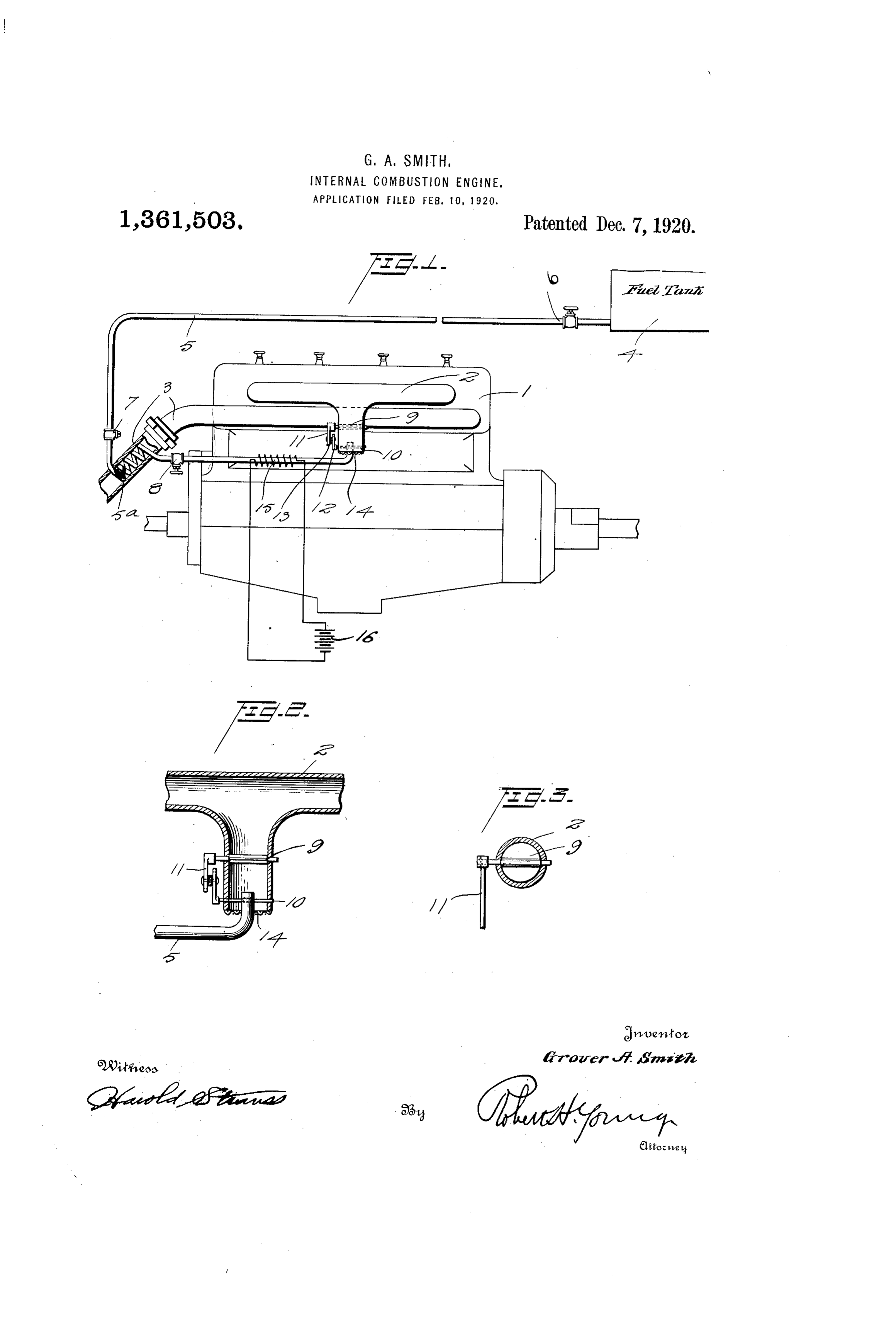
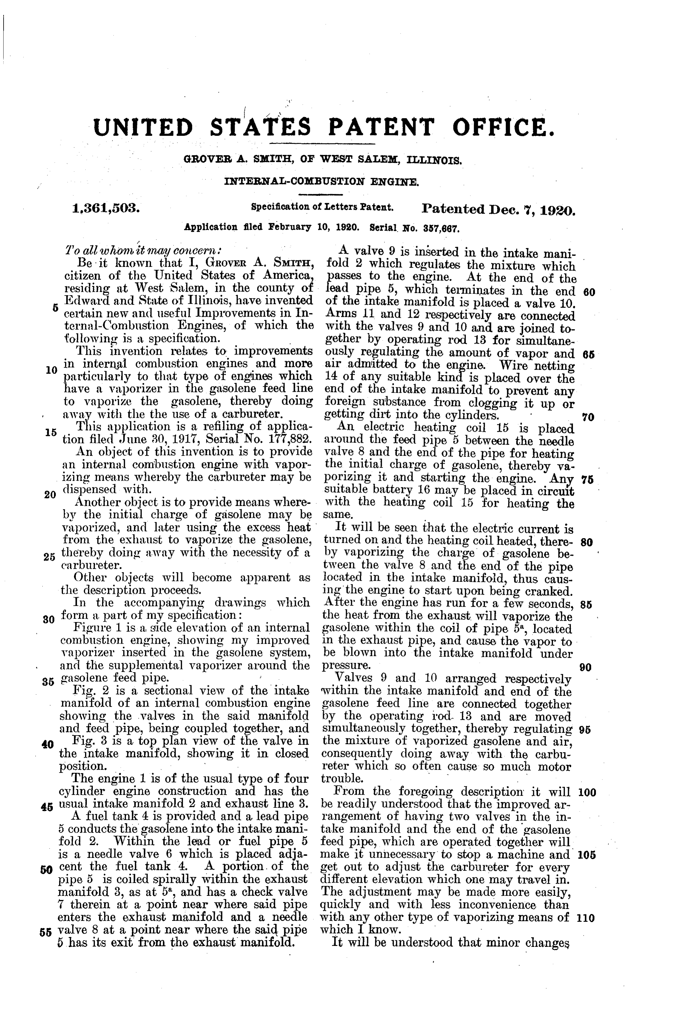
To all whom it may concern (A valve 9 is inserted in the intake mani Be it known that I, GROVER A. SMITH, fold 2 which regulates the mixture which citizen of the United States of America, passes to the engine. At the end of the residing at West Salem, in the county of lead pipe 5, which terminates in the end 60 5 Edward and State of Illinois, have invented of the intake manifold is placed a valve 10. certain new and useful Improvements in In Arms 11 and 12 respectively are connected ternal-Combustion Engines, of which the With the valves 9 and 10 and are joined to following is a specification. gether by operating rod 13 for simultane This invention relates to improvements ously regulating the amount of vapor and 65 in internal combustion engines and more air admitted to the engine. Wire netting particularly to that type of engines which 14 of any suitable kind is placed over the have a vaporizer in the gasolene feed line end of the intake manifold to prevent any to vaporize the gasolene, thereby doing foreign substance from clogging it up or away with the the use of a carbureter. getting dirt into the cylinders. 70 5 This application is a refiling of applica An electric heating coil 15 is placed tion filed June 30, 1917, Serial No. 177,882. around the feed pipe 5 between the needle An object of this invention is to provide Yalve 8 and the end of the pipe for heating an internal combustion engine with vapor the initial charge of gasolene, thereby vs. izing means whereby the carbureter may be porizing it and starting the engine. Any 75 dispensed with. Suitable battery 16 may be placed in circuit Another object is to provide means where with the heating coil 15 for heating the by the initial charge of gasolene may be Sale.
vaporized, and later using the excess heat It will be seen that the electric current is from the exhaust to vaporize the gasolene, turned on and the heating coil heated, there 80 thereby doing away with the necessity of a by vaporizing the charge of gasoléne be carbureter. tween the valve 8 and the end of the pipe Other objects will become apparent as located in the intake manifold, thus caus the description proceeds. ing the engine to start upon being cranked. In the accompanying drawings which After the engine has run for a few seconds, 85 80 form a part of my specification: the heat from the exhaust will vaporize the Figure 1 is a side elevation of an internal gasolene within the coil of pipe 5, located combustion engine, showing my improved in the exhaust pipe, and cause the vapor to: vaporizer inserted in the gasolene system, be blown into the intake manifold under and the supplemental vaporizer around the pressure. 90 35 gasolene feed pipe. Valves 9 and 10 arranged respectively Fig. 2 is a sectional view of the intake Within the intake manifold and end of the manifold of an internal combustion engine gasolene feed line are connected together showing the valves in the said manifold by the operating rod. 13 and are moved and feed pipe, being coupled together, and simultaneously together, thereby regulating 95 40 Fig. 3 is a top plan view of the valve in the mixture of vaporized gasolene and air, the intake manifold, showing it in closed consequently doing away with the carbu position. reter which so often cause so much motor The engine 1 is of the usual type of four trouble. - cylinder engine construction and has the From the foregoing description it will 100 45 usual intake manifold 2 and exhaust line 3. be readily understood that the improved ar A fuel tank 4 is provided and a lead pipe rangement of having two valves in the in 5 conducts the gasolene into the intake mani take manifold and the end of the gasolene fold 2. Within the lead or fuel pipe 5 feed pipe, which are operated together will is a needle valve 6 which is placed adja make it unnecessary to stop a machine and 05 50 cent the fuel tank 4. A portion of the get out to adjust the carbureter for every pipe 5 is coiled spirally within the exhaust different elevation which one may travelin. manifold 3, as at 5", and has a check valve The adjustment may be made more easily, 7 therein at a point near where said pipe quickly and with less inconvenience than enters the exhaust manifold and a needle with any other type of vaporizing means of 110 5 valve 8 at a point near where the said pipe which I know. m 5 has its exit from the exhaust manifold. It will be understood that minor changes
Page 3
in detail of construction may be resorted to charge end of the line and the exhaust mani without departing from the spirit of the fold adjacent to the exhaust manifold, invention. whereby the portion of the line between said 15 What I claim is: ... last mentioned valve and the intake mani A vaporizer for internal combustion en fold forms a reservoir of superheated and gines, comprising a fuel feed line, a portion expended vapor for the initial charge of of said line passing through the engine ex the engine, and a throttle valve in said in- - , haust manifold, wherein the fuel is vapor take manifold. 20 ized and superheated, a check valve in said In testimony whereof. I affix. my signa 10 line, intermediate of the fuel tank and the ture. w portion thereof in the exhaust manifold, a needle valve in said line between the dis-, GROVER A. SMITH,
Provenance
- Collection
- Cited prior art
- Original PDF
- patentimages.storage.googleapis.com →
- Filed
- 1920-02-10
- Pages
- 3
- Method
- pdftotext (the PDF's own text layer) + pdftoppm 300dpi page scans
- Source
- Google Patents bibliographic record
- Granted
- 1920-12-07
- Inventors
- Grover A Smith
- Transcribed from
- patentimages.storage.googleapis.com →