patent · US5599437
Electrolysis of electroactive species using pulsed current
4 February 1997
Page 1 — bibliographic record
III III
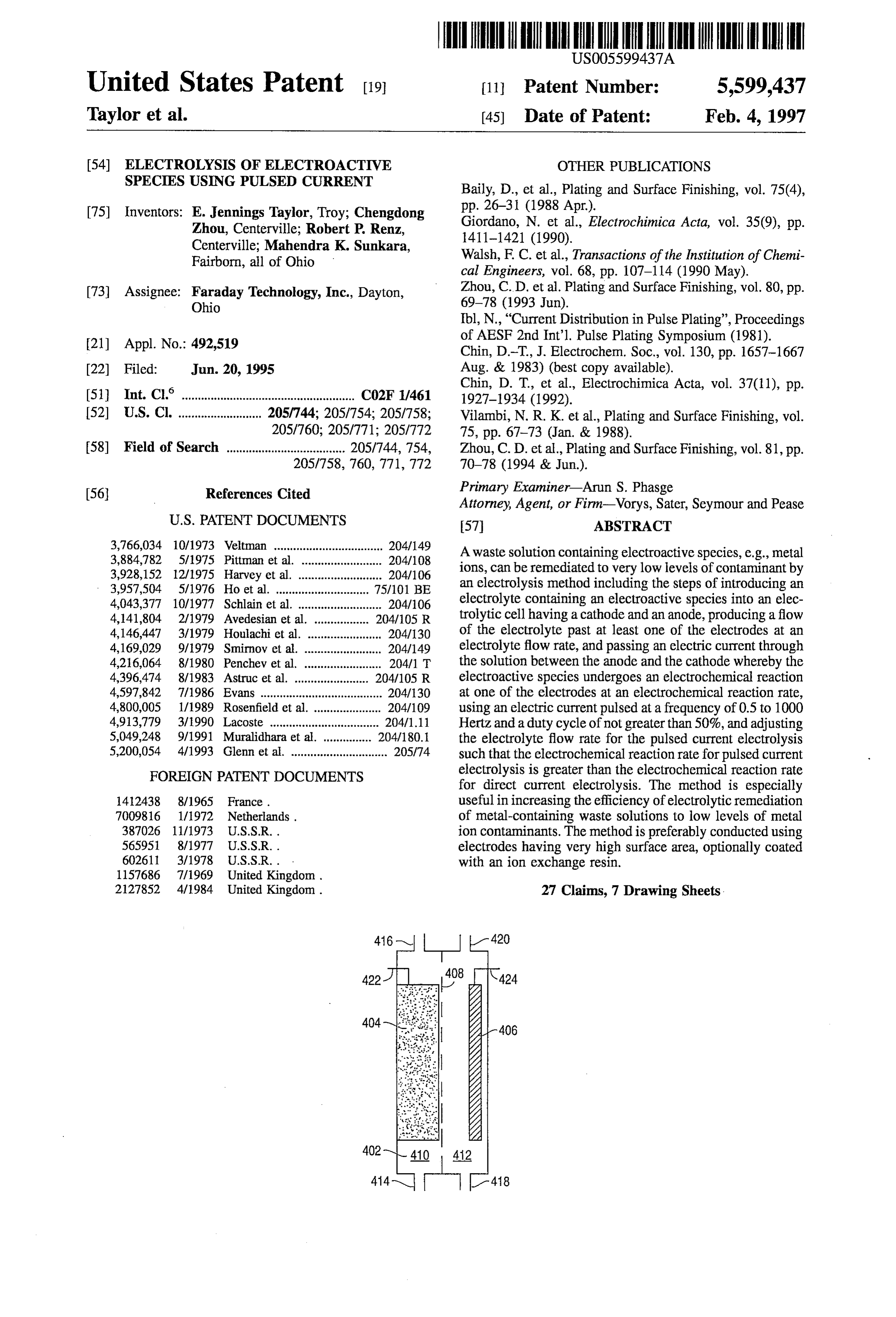
United States Patent (19) 11 Patent Number: 5,599.437 Taylor et al. (45) Date of Patent: Feb. 4, 1997 54 ELECTROLYSIS OF ELECTROACTIVE OTHER PUBLICATIONS SPECIES USING PULSED CURRENT Baily, D., et al., Plating and Surface Finishing, vol. 75(4), (75) Inventors: E. Jennings Taylor, Troy; Chengdong pp. 26-31 (1988 Apr.).
Zhou, Centerville; Robert P. Renz, Giordano, N. et al., Electrochimica Acta, vol. 35(9), pp. Centerville; Mahendra K. Sunkara, 1411-1421 (1990).
Fairborn, all of Ohio Walsh, F. C. et al., Transactions of the Institution of Chemi
(73) Assignee: Eday Technology, Inc., Dayton, Zhou, C.D.
al. Plating and Surface Finishing, vol. 80, pp.
Ibl, N., "Current Distribution in Pulse Plating", Proceedings of AESF 2nd Int'l, Pulse Plating Symposium (1981).
(21) Appl. No.: 492,519 2. "ESYSPE pp. 1657-1667 22 Filed: Jun. 20, 1995 Aug. & 1983) (best copy available). Chin, D. T., et al., Electrochimica Acta, vol. 37(11), pp.
(51) Int. Cl. ....................................... CO2F 1/461 1927-1934 (1992).
52 U.S. Cl. .......................... 205/744; 205/754; 205/758; Vilambi, N. R. K. et al., Plating and Surface Finishing, vol. 205/760; 205/771; 205/772 75, pp. 67-73 (Jan. & 1988).
58) Field of Search ..................................... 205/744, 754, Zhou, C. D. et al., Plating and Surface Finishing, vol. 81, pp.
Primary Examiner-Arun S. Phasge 56) References Cited Attorney, Agent, or Firm-Vorys, Sater, Seymour and Pease
3,766,034 10/1973 Veltman .................................. 204/149 A waste solution containing electroactive species, e.g., metal
ions, can be remediated to very low levels of contaminant by - 3,957,504 5/1976 Ho etal 75/101 BE an electrolysis method including the steps of introducing an 4,043,377 10/1977 Schlain et al. .. - - - - - 204/106 electrolyte containing an electroactive species into an elec 4,141,804 2/1979 Avedesian et al. . 204/105 R trolytic cell having a cathode and an anode, producing a flow 4,146,447 3/1979 Houlachi et al. ... ... 204/130 of the electrolyte past at least one of the electrodes at an 4,169,029 9/1979 Smirnov et al. ... 204/149 electrolyte flow rate, and passing an electric current through 4,216,064 8/1980 Penchev et al. . a 204/1 T the solution between the anode and the cathode whereby the 4,396,474 8/1983 Astrucet al. .... 204/105 R electroactive species undergoes an electrochemical reaction 4,597,842 7/1986 Evans .................. ... 204/130 at one of the electrodes at an electrochemical reaction rate, 4,800,005 1/1989 Rosenfield et al. . ... 204/109 using an electric current pulsed at a frequency of 0.5 to 1000 4,913,779 3/1990 Lacoste ................... ... 204/1.11 Hertz and a duty cycle of not greater than 50%, and adjusting 5,049,248 9/1991 Muralidhara et al. 204/180.1 the electrolyte flow rate for the pulsed current electrolysis 5,200,054 4/1993 Glenn et al. .............................. 205/74 such that the electrochemical reaction rate for pulsed current electrolysis is greater than the electrochemical reaction rate
FOREIGN PATENT DOCUMENTS for direct current electrolysis. The method is especially 1412438 8/1965 France. useful in increasing the efficiency of electrolytic remediation 7009816 1/1972 Netherlands. of metal-containing waste solutions to low levels of metal 387026 11/1973 U.S.S.R. . ion contaminants. The method is preferably conducted using 565951 8/1977 U.S.S.R. . electrodes having very high surface area, optionally coated 602611 3/1978 U.S.S.R. . . with an ion exchange resin.
2127852 4/1984 United Kingdom. 27 Claims, 7 Drawing Sheets.
Page 2
Drawing sheet — no readable text.
Page 3
Drawing sheet — no readable text.
Page 4
FIG. 5
Cu(II) RECOVERY: 0.51/MIN; PC: 1.OHz,lave = 10A
TATION
2. O 50 100 150 200 250 300
ELECTROLYSIS TIME (MIN)
FIG. 6
Cu(II) RECOVERY: 0.5/MIN; PC: 1.OHzlave = 10A
CURRENT
EFFICIENCY 15
O 20 40 60 80 100 120 140 160 80 Cu(II) CONCENTRATION (ppm)
Page 5
FIG. 7
Cu(II) RECOVERY: 0.51/MIN; PC: 1.OHz,lave = 10A
ENERGY 80
CONSUMPTION
O 20 40 60 80 100 120 140 160 180 Cu(II) CONCENTRATION (ppm)
FIG. 8
Cu(II) RECOVERY: 0.51/MIN; PC: 1.OHzlave = 10A
TRATION g
2. O 50 100 150 200 250
ELECTROLYSIS TIME (MIN)
Page 6
FIG. 9
Cu(II) RECOVERY: 0.51/MIN; PC: 1.OHz,lave = 10A
CURRENT 20
EFFICIENCY 15
O 20 40 60 80 100 120 140 160 180 Cu(II) CONCENTRATION (ppm)
FIG 10
Cu(II) RECOVERY: 0.5IIMIN; PC: 1.OHz,lave = 10A
ENERGY
CONSUMPION
O 20 40 60 80 100 120 140 160 180 Cu(II) CONCENTRATION (ppm)
Page 7
Drawing sheet — no readable text.
Page 8
COMPARISON BETWEEN THE BEST PC AND BEST DC
CONDITION: 40 AAVERAGE CURRENT
COPPER 100
CONCENTRATION
(ppm)
ELECTROLYSIS TIME (MIN)
COMPARISON OF THE BEST PC AND BEST DC : 40A
AVERAGE CURRENT
CURRENT 60
EFFICIENCY
3)" 40 -A-PC:Hz, 10%, 0.5L/min)
COPPER CONCENTRATION (ppm)
Page 9
ELECTROLYSIS OF ELECTROACTIVE quently becomes more negative than the potential for evo SPECIES USENG PULSED CURRENT lution of hydrogen. Consequently, the undesired evolution of hydrogen is likely to occur. Because of the hydrogen evo
ORIGIN OF THE INVENTION lution reaction, the current efficiency will be relatively low when metals are recovered from dilute solution.
The experimental work leading to this invention was One way to minimize the effect of low metal ion concen funded in part by the U.S. Government Advanced Research tration on the efficiency of the electrolytic process is to Project Agency Contract No. MDA972-93-C-0036. provide a high mass transfer rate. This is evident from a consideration of the concentration gradients produced in the
BACKGROUND OF THE INVENTION O solution by the electrolytic process. As the metal ions I. Field of the Invention adjacent to the cathode are attracted to it and precipitated the concentration of the metal ions near the cathode is
This invention relates to methods of purifying waste decreased, and the potential required for their deposition Solutions containing electroactive species and more particu becomes more negative. In order to increase the rate of metal larly to methods for purifying such solutions by electrolytic 15 deposition the rate of mass transfer from the bulk of the reaction using pulsed current electrolysis. The invention also Solution to the depleted region adjacent to the electrode must relates to purification of metal-containing waste solutions by be increased. Evidently the amount of metal ion in the electrolytic deposition of the metal on porous electrodes volume adjacent to the cathode can be increased by increas having a high specific surface area using pulsed current ing either the rate at which the ions are moved from the bulk electrolysis. 20 solution to the near-electrode volume or by increasing the 1. Brief Description of the Prior Art area of the electrode itself, thereby increasing the volume of Waste solutions containing pollutants that are electroac the near-electrode layer. Merely increasing the area of flat tive species can be purified by an electrochemical process plate electrodes would provide some benefit, but at the cost wherein the pollutants are destroyed or precipitated by of increasing size and complexity of the electrochemical cell oxidation or reduction at electrodes in contact with the 25 itself. Consequently, efforts at increasing the mass transfer solution. rate in electrochemical cells have concentrated on using Waste solutions containing metals in ionic form may be forced flow of electrolyte using an external pump, mechani freed of the polluting metal ions by electrodepositing them cally moving the electrode itself within the solutions, the use as free metal at the cathode of an electrochemical cell. The of turbulence promoting structures and conditions in flow major advantage of the electrochemical method for treating 30 systems, the use of stirring by gas sparging, and the use of metal-containing waste water is that the metal ions can be three-dimensional electrodes to provide increased electrode recovered in metallic form, without the use of chemical surface area in a given cell volume. reagents and without the generation of secondary wastes. A number of workers have investigated the electrochemi However, electrochemical purification of metal-containing 35 cal process of metal recovery with a view to improving its waste solutions has encountered certain difficulties due to efficiency. Baily, D., et al., Plat. and Surf Finish, 75 (4), p the stringent limits on metal ion concentration that have 26 (1988), used porous carbon fiber flow-through electrodes been imposed by the ever-stricter legal requirements for to increase the active surface area of the cathode and hence purity of industrial effluent streams. reduce the mass transfer limitations. However, the power Other electroactive species found as pollutants in waste 40 tion, as these of consumption Such an arrangement is too great. In addi flow-through electrodes become blocked with water, e.g., cyanide ions, can be removed by electrochemical deposited metal, the buildup in pressure drop across the oxidation at an anode.
recovery unit can result in leakage and mechanical prob
The major challenge to electrochemical processing of low lems.
concentration waste water is the low current efficiency and More recently, Walsh, F. C., and Gabe, D. R., Trans. Inst. high effluent concentration due to the hydrogen evolution 45 Chem. Eng., 68, p. 107 (1990), approached the mass trans side reaction. The extent of hydrogen evolution is dependent port problem of metal recovery by working in a turbulent on the electrode potential, the hydrogen overpotential (n) flow electrochemical reactor. Zhou, C. D., and Chin, D. T., on the metal being deposited and the pH of the solution. The Plat, and Surf Fin. 80, p. 67 (1993), investigated an current efficiency for the common case of deposition of a electrochemical process for simultaneous metal recovery metal ion may be defined as: 50 and cyanide destruction using a plating barrel-type cathode
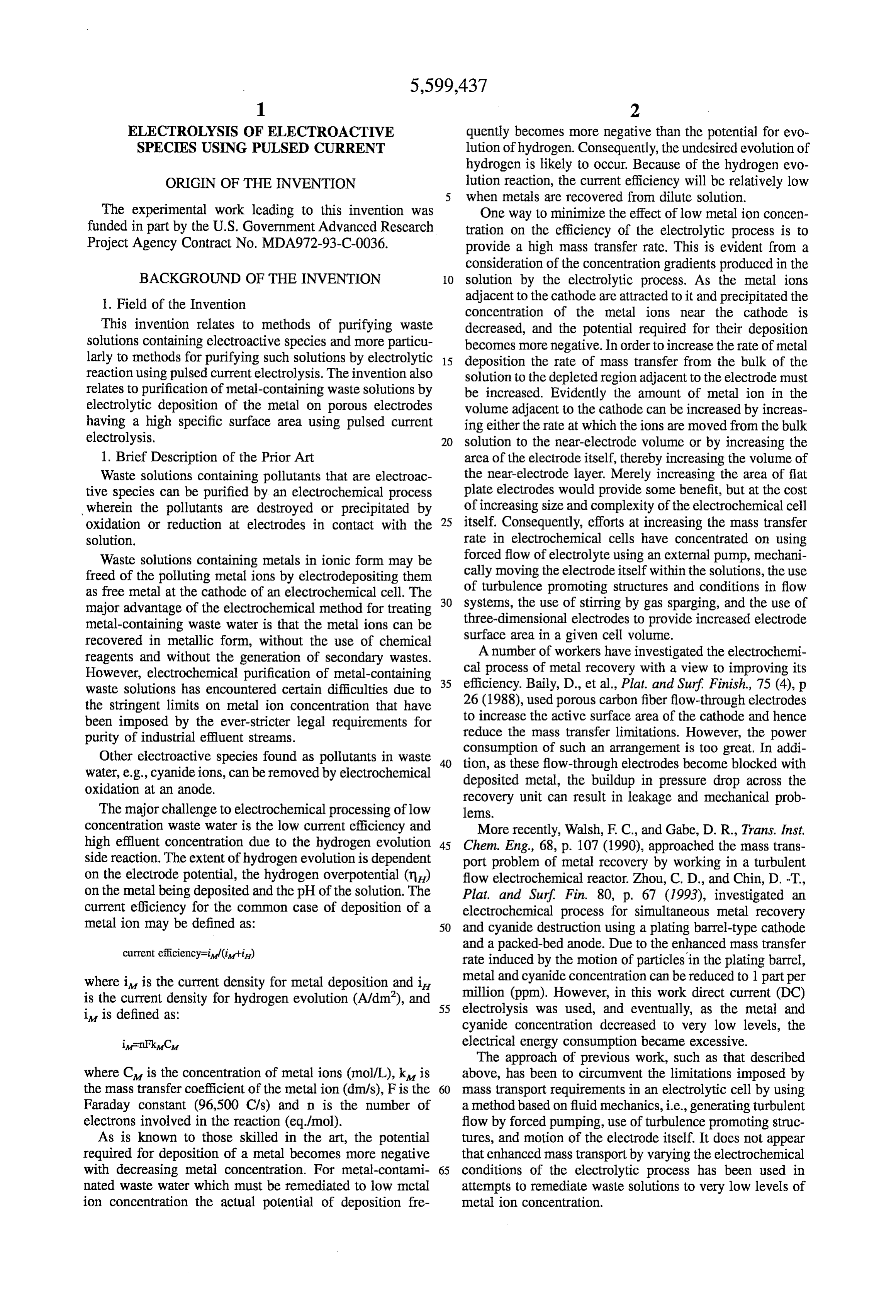
current efficiency Fil(iii) and a packed-bed anode. Due to the enhanced mass transfer rate induced by the motion of particles in the plating barrel, where it is the current density for metal deposition and it metal and cyanide concentration can be reduced to 1 part per million (ppm). However, in this work direct current (DC) is the current density for hydrogen evolution (A/dm'), and 55 electrolysis it is defined as: was used, and eventually, as the metal and cyanide concentration decreased to very low levels, the electrical energy consumption became excessive.
The approach of previous work, such as that described where C is the concentration of metal ions (mol/L), k is above, has been to circumvent the limitations imposed by the mass transfer coefficient of the metalion (dim/s), F is the 60 mass transport requirements in an electrolytic cell by using Faraday constant (96,500 Cls) and n is the number of a method based on fluid mechanics, i.e., generating turbulent electrons involved in the reaction (eq/mol). flow by forced pumping, use of turbulence promoting struc As is known to those skilled in the art, the potential tures, and motion of the electrode itself. It does not appear required for deposition of a metal becomes more negative that enhanced mass transport by varying the electrochemical with decreasing metal concentration. For metal-contami 65 conditions of the electrolytic process has been used in nated waste water which must be remediated to low metal attempts to remediate waste solutions to very low levels of ion concentration the actual potential of deposition fre metal ion concentration.
Page 10
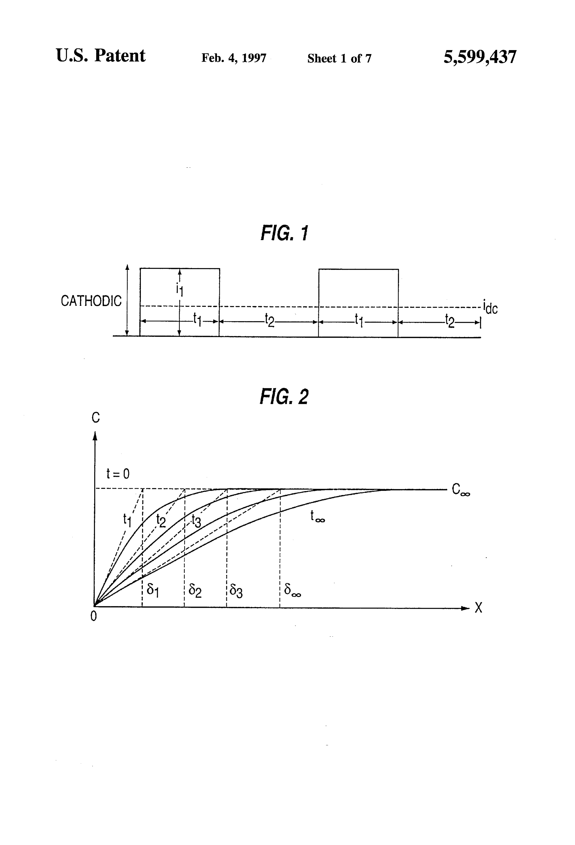
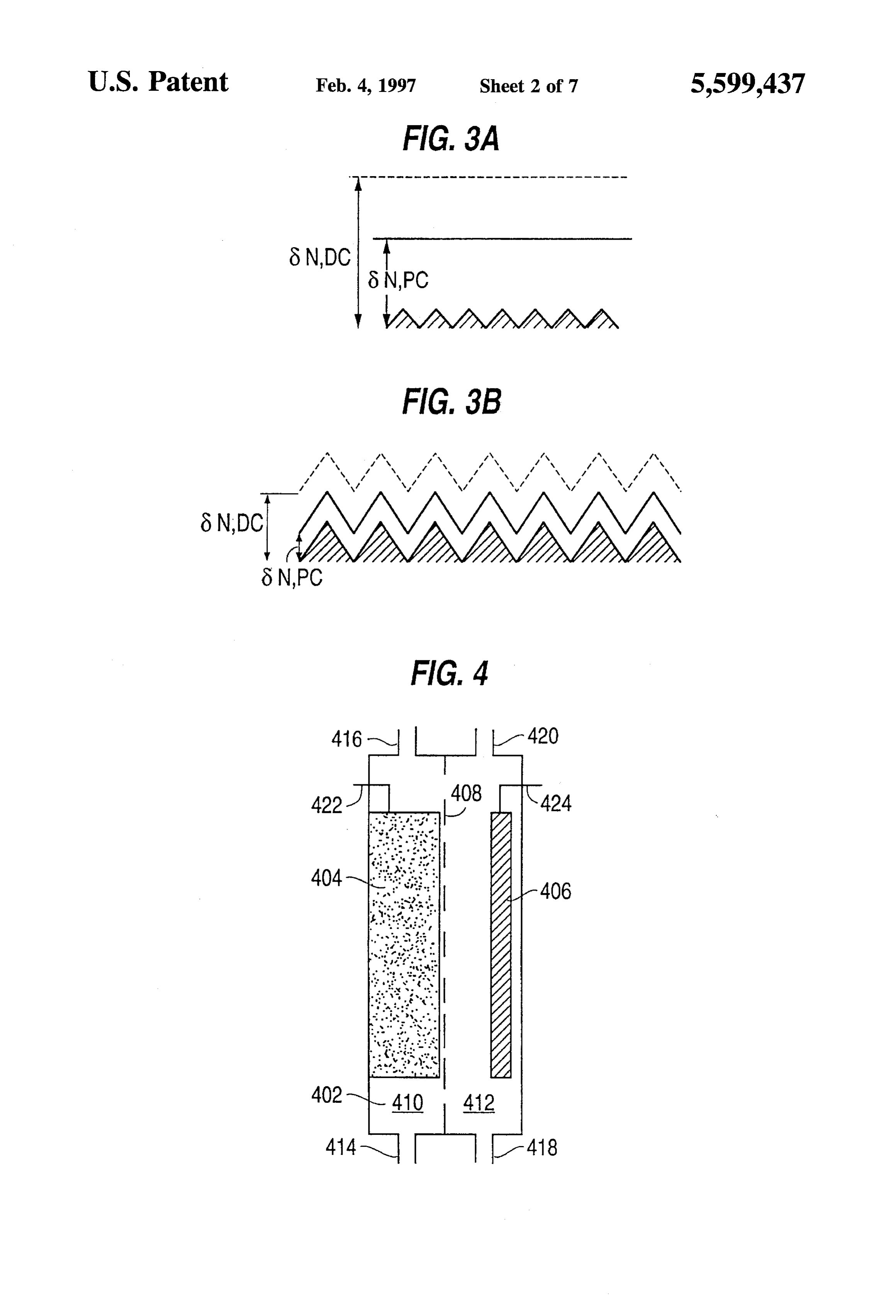
Pulsed current electrolysis of solutions containing rela FIG. 2 illustrates the mass transfer near the electrode of an tively high concentrations of copper ions generated in pro electrolytic cell that is caused by electrolysis of an electro duction of copper by leaching of ores has been used for active species, e.g. by electrodeposition of a metal. recovery of copper from the leaching solutions as disclosed FIG. 3a illustrates the relation between the concentration in Pittman et al., U.S. Pat. No. 3,884,782. Pittman uses diffusion layer for DC and PC produced by electrolysis at an massive electrodes, e.g., stainless steel sheets, on which to electrode wherein the roughness of the surface is small plate out the copper rather than porous electrodes. The compared with the thickness of the diffusion layer. pulsed current is disclosed as increasing the purity of the FIG. 3b illustrates the relation between the concentration deposited copper.
Accordingly a need has continued to exist for a method of O electrode layer diffusion for DC and PC produced by electrolysis at an increasing the efficiency of electrochemical remediation of compared with the the wherein roughness of the surface is large thickness of the diffusion layer.
waste solutions and particularly for a method of removing FIG. 4 illustrates one module of an electrolytic apparatus metals from dilute waste solutions by electrodeposition. used in the experimental investigations reported in the
Examples.
SUMMARY OF THE INVENTION FIG. 5 illustrates the concentration of copper (II) ions as a function of time for PC and DC using a porous permeable
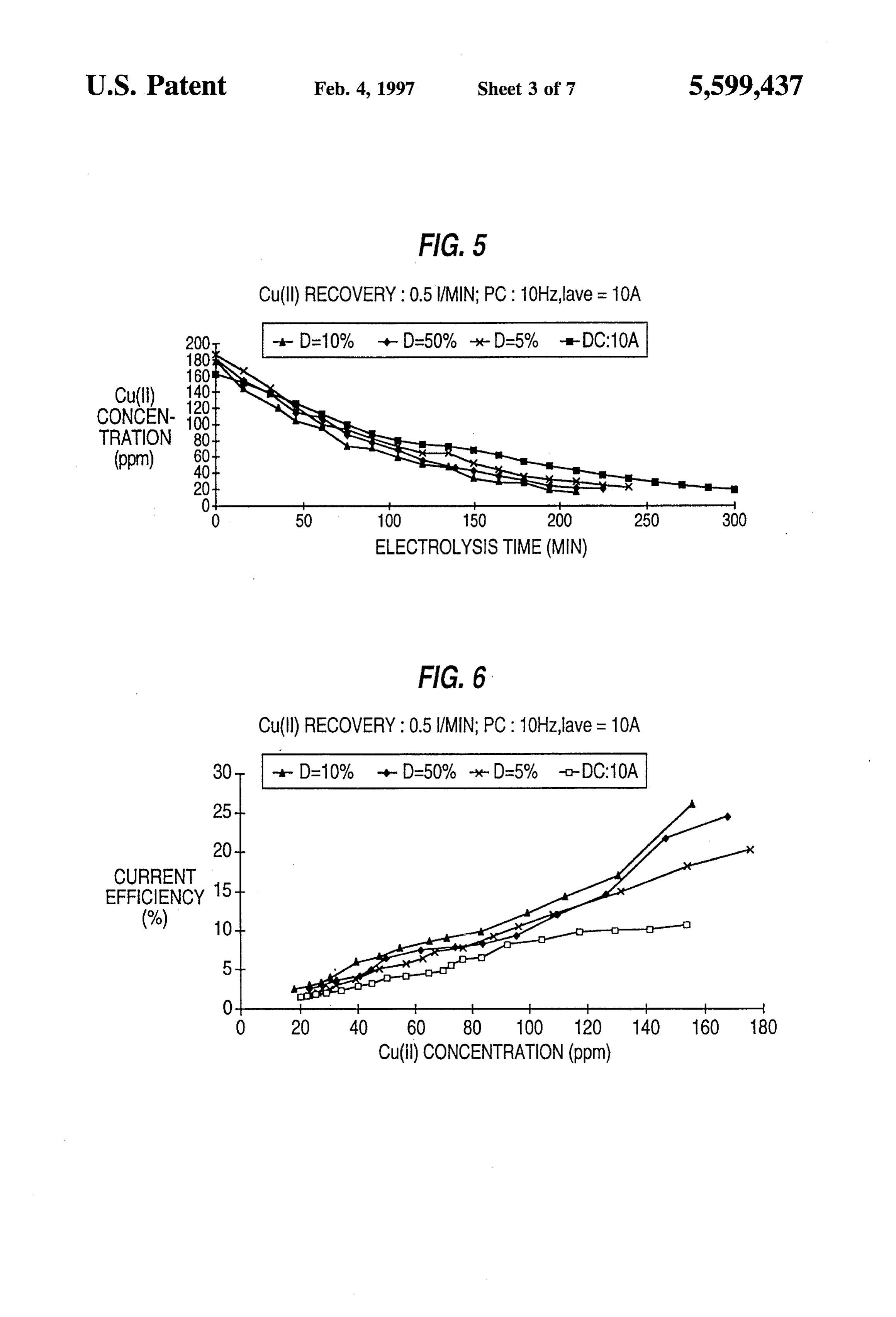
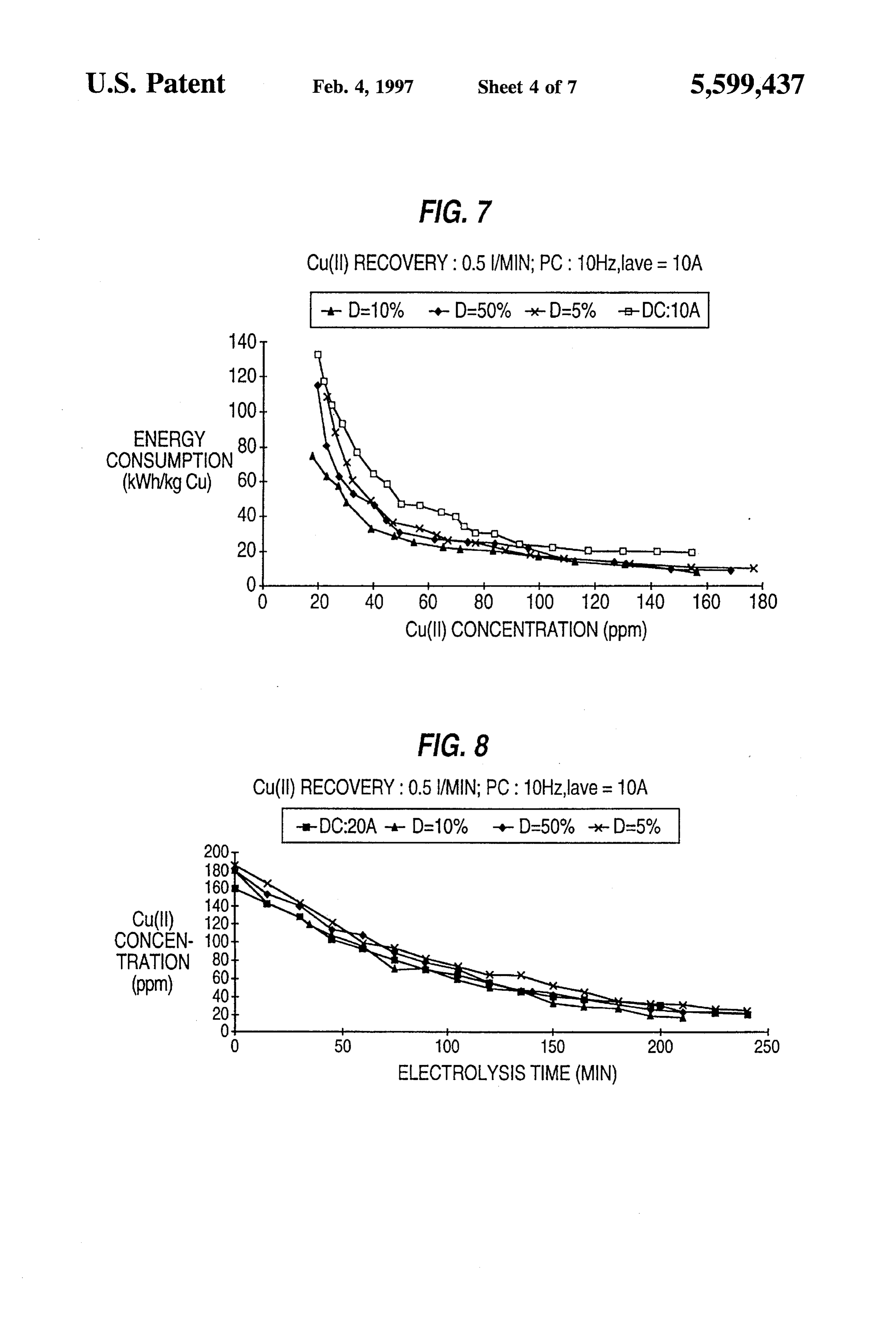
This problem has now been alleviated by the method of electrode wherein the flow rate of electrolyte through the this invention wherein a waste solution containing electro electrode is low enough to provide a diffusion layer that is active species, e.g., metal ions, is treated by a method 20 relatively thick compared to the surface roughness of the comprising electrode, as found in the experiment of Example 1. introducing a solution containing an electroactive species FIG. 6 illustrates the cathodic current efficiency as a into an electrolytic cell having a cathode and an anode, function of the copper (II) ion concentration for the experi producing a flow of said electrolyte past at least one of the ments plotted in FIG. 5.
electrodes at an electrolyte flow rate, 25 FIG. 7 illustrates the electric energy consumption as a passing an electric current through the solution between function of the copper (II) ion concentration for the experi the anode and the cathode whereby the electroactive ments potted in FIG. 5.
Species undergoes an electrochemical reaction at one of FIG. 8 illustrates additional data for the concentration of the electrodes, cathode or anode, at an electrochemical copper (II) ions as a function of time for PC and DC under reaction rate, wherein the electric current is a pulsed 30 the flow conditions of Example 1 using varied conditions of current pulsed at a frequency of 0.5 to 1000 Hertz and electrolysis current.
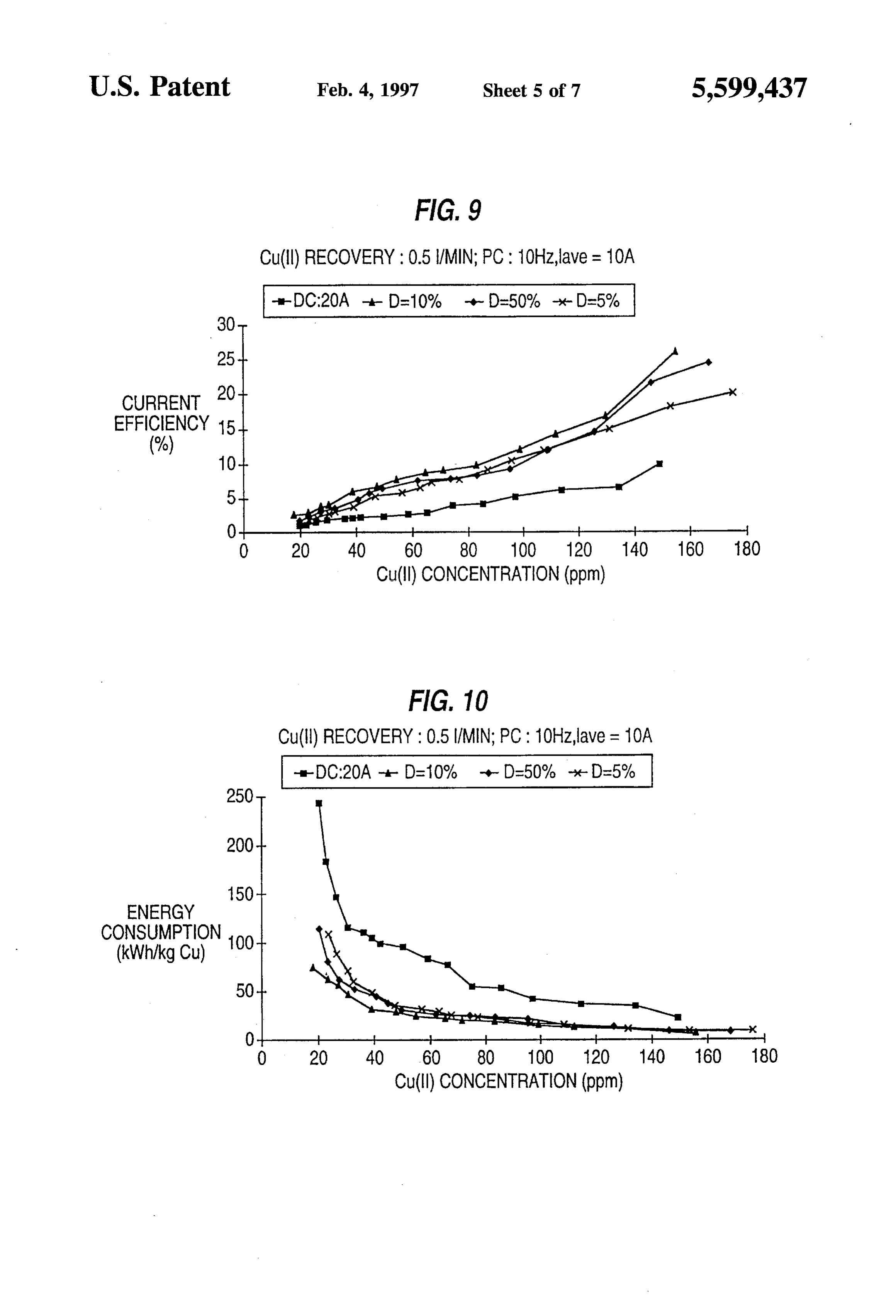
having a duty cycle of not greater than 50%, and the FIG. 9 illustrates the cathodic current efficiency as a flow rate is defined as a pulsed current electrolyte flow function of the copper (II) ion concentration for the experi rate, and 35 ments plotted in FIG. 8.
adjusting the pulsed current electrolyte flow rate such that FIG. 10 illustrates the electric energy consumption as a the electrochemical reaction rate when the current is pulsed current is greater than the electrochemical reac function of the copper(II) ion concentration for the experi tion rate when the electric current is direct current. ments plotted in FIG. 8.
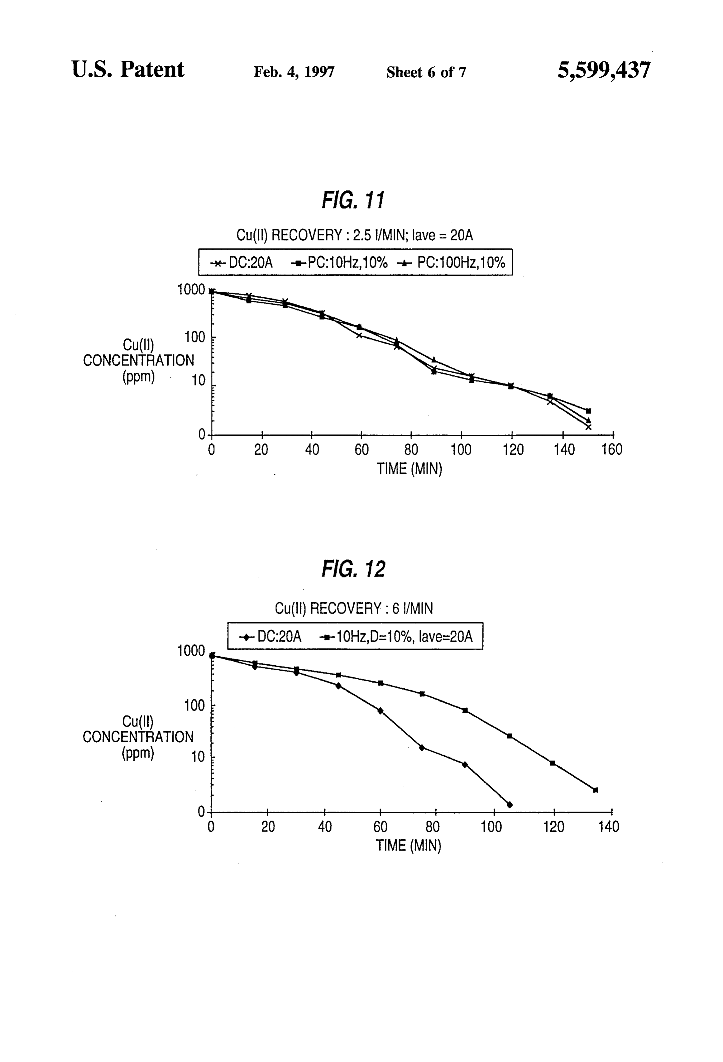
Accordingly, it is an object of the invention to provide a 40 FIG. 11 illustrates the concentration of copper(II) ions as method of purifying waste solutions by an electrochemical a function of time for PC and DC using a porous permeable proceSS. electrode wherein the flow rate of electrolyte through the A further object is to remove metal ions from waste electrode is somewhat higher than that which produces a solutions by electrolytic deposition. diffusion layer that is relatively thick compared to the A further object is to remove metal ions from solutions 45 surface roughness of the electrode, as found in the experi wherein the ions are present in low concentration. ment of Example 2.
A further object is to provide a method of electrodeposi FIG. 12 illustrates the concentration of copper(II) ions as tion of metal from solution using pulsed current. a function of time for PC and DC using a porous permeable A further object is to provide a method of electrodeposi electrode wherein the flow rate of electrolyte through the tion of metals from waste solutions using a cathode of very 50 electrode is substantially higher than that which produces a high surface area. diffusion layer that is relatively thick compared to the A further object is to provide a method for increasing the surface roughness of the electrode, as found in the experi efficiency of electrolytic reactions in purifying waste solu ment of Example 3.
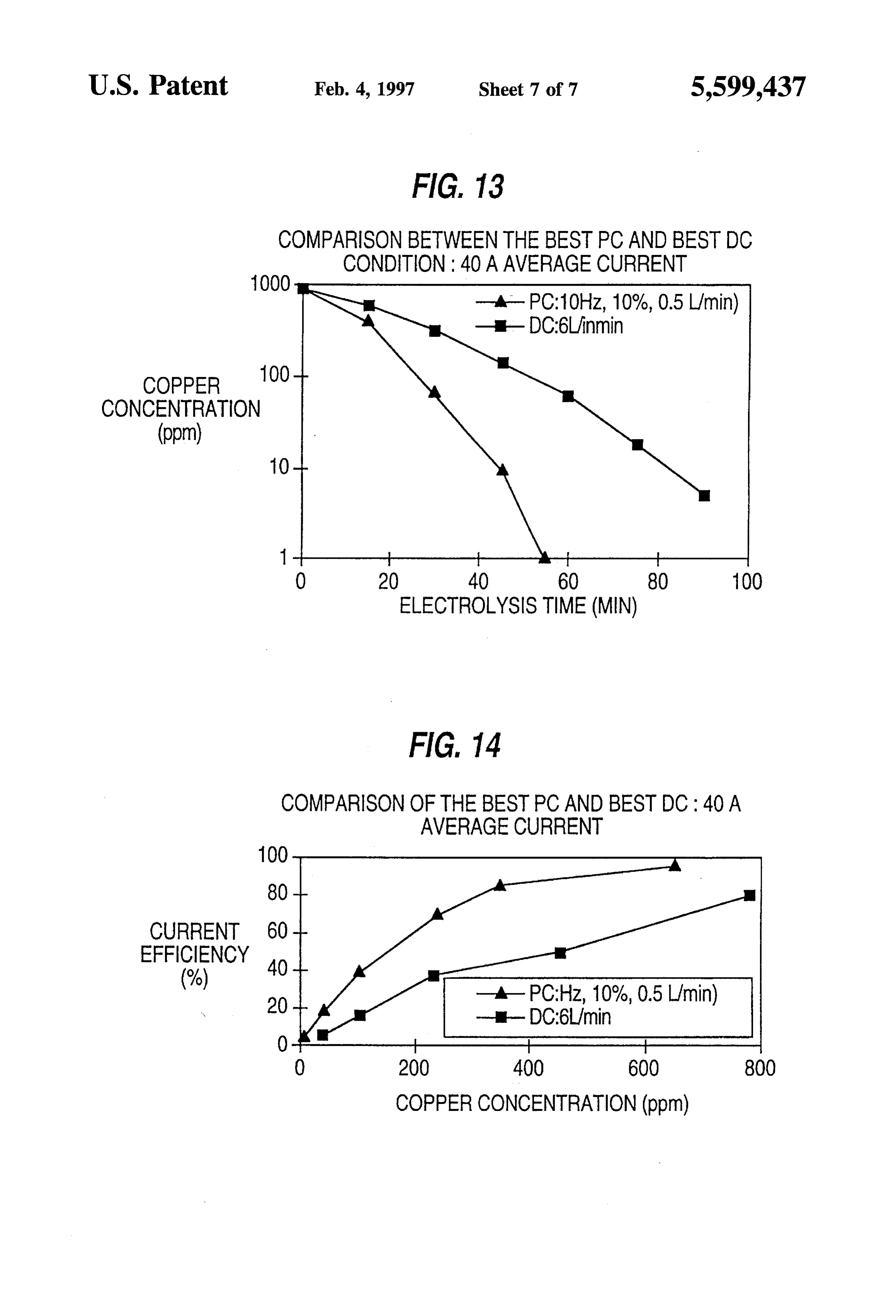
tions. FIG. 13 shows a comparison of the rate of removal of A further object is to provide a method for electrodepo 55 metal ions from a solution for PC and DC at an average sition of metal ions from waste solutions. current of 40A for the best conditions for each mode in the A further object is to provide a method of removing experiments of Example 4.
metals from waste solutions by electrolysis using a cathode FIG. 14 shows a comparison of the current efficiency for having a very high surface are which is coated with an ion the PC and DC electrolyses in the experiments of Example exchange resin.
Further objects of the invention will become apparent from the description of the invention which follows. DETAILED DESCRIPTION OF THE
INVENTION AND PREFERRED
EMBODIMENTS
BRIEF DESCRIPTION OF THE DRAWINGS
65 According to this invention, the mass transport of an
FIG. 1 is a schematic diagram of a pulsed current wave electroactive species, e.g., metal ions from the bulk solution form of the type used in the method of this invention. to an electrode, e.g., the cathode, of an electrochemical cell
Page 11
S 6 is enhanced by the use of pulsed current (PC) electrolysis becomes more efficient. Therefore, a low terminal concen instead of DC electrolysis. The effective area of the elec tration can be obtained by increasing the mass transfer rate trode, i.e., the area of the electrode surface that is active in and/or the electrode surface area. producing the electrochemical reaction is also increased by Consequently, it can be seen that an improvement in using a porous electrode that is permeable to the electrolyte electrochemical remediation of waste water can be achieved and causing the electrolyte to flow through the porous by enhancing the mass transfer rate and/or electrode surface electrode at a rate that enhances the effective area, as shown area, i.e., increasing the factor kA. by the greater efficiency as compared with higher flow rates. According to the invention the mass transfer rate is It is believed that the enhanced effective area is the result of operating the cell under conditions wherein the diffusion 10 and increased by using pulsed current in the electrochemical cell layer in the electrode is substantially thicker than the rough the effective area of the electrode, i.e., the area useful in ness of the electrode surface. effecting electrochemical reaction, e.g., deposition of metal, may be increased by using pulsed current electrolysis under
The invention will be discussed in the following in terms certain conditions.
of plating of metalions, e.g., copper ions, onto a cathode as Generally, the increase in mass transfer rate by methods the pure metal. However, it will be understood by those 15 relying on fluid mechanics is mostly due to forced convec skilled in the art that the invention is applicable to any tion in bulk solution, although the thickness of the relatively electrode reaction occurring is an electrochemical cell, quiescent diffusion layer adjacent to the electrode may also whether electrooxidation at the anode or electroreduction at the cathode. be reduced by such measures. Even when the relative motion between the electrolyte and the electrode is vigorous, the
The improved efficiency of electrolytic reaction according 20 transport of reactant from the bulk solution to the electrode to the invention can be better understood by reference to is limited by its diffusion in the Nernst diffusion layer near certain considerations governing the kinetics of the process. the electrode surface. It has now been found that pulsed The electrochemical reaction is conducted in a cell which is current (PC) can enhance the mass transfer rate by greatly a particular type of chemical reactor. The equations describ decreasing the effective diffusion layer thickness. ing the change in concentration of electrochemically active 25 When a pulsed voltage is imposed on the terminals of an species are well-known for both batch and continuous electrochemical cell a corresponding pulsed current through processes. the cell is produced, accordingly, in the following discussion For a batch reactor the following equation governs the it will be understood that pulsed current and pulsed voltage concentration of reagent at time t. are generally interchangeable. FIG. 1 illustrates schemati 30 cally a square wave pulsed current (or voltage) used in the
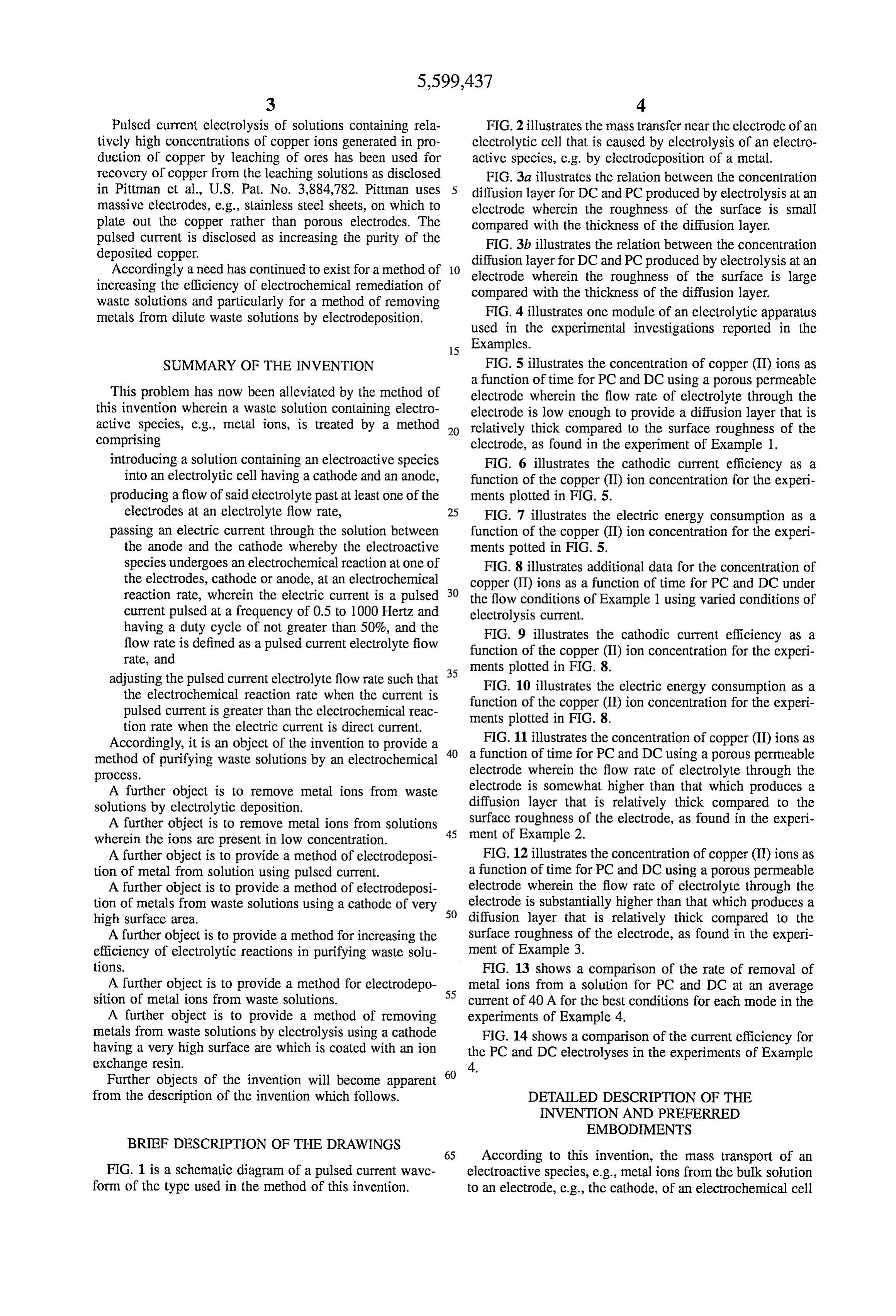
C/C-exp (-kAt/W) (1) method of the invention. A peak current i is turned on for a period of time t called the on-time, followed by a zero where V is the solution volume in liters (L), C is the current for a period of time t called the off-time. The sum initial concentration of reactive species (mol/L), C, is the of on-time and off-time is known as the period of the pulse concentration of reactive species at time t (mol/L), K is the 35 and the inverse of the period is known as the frequency of mass transfer coefficient in decimeters per second (dm/s), the pulse. The percent on-time in a pulse is defined as the and A is the electrode surface area in square decimeters duty-cycle (D) of the pulse. The average current is equiva (dm). lent to a DC current that transports the same amount of For a continuous process two kinds of reactors can be charge in the time taken by one cycle (t+t) of the pulsed considered. One is a continuous stirred-tank reactor (CSTR), 40 current and is shown as it. The current density at the in which the mixing of solution is complete so that the electrode during the on-time is also known as the peak pulse properties (e.g., concentration, temperature) of the reaction current density and the average current density is defined as mixture are uniform in all parts of the reactor except the the time average of the instantaneous current density over a electrode surface. Therefore, the properties of the reaction pulse period. The on-time, off-time and peak pulse current mixture in the reactor are also the same as those in the exit 45 density are additional parameters available in the PC elec stream. Another is the plug-flow reactor (PFR), in which trolysis process, but not in DC electrolysis. there is no mixing in the direction of flow and complete In DC electrolysis, the cell geometry, electrolyte compo mixing perpendicular to the direction of flow. In practice sition, agitation, and current density are fixed and therefore many reactors show intermediate behavior.
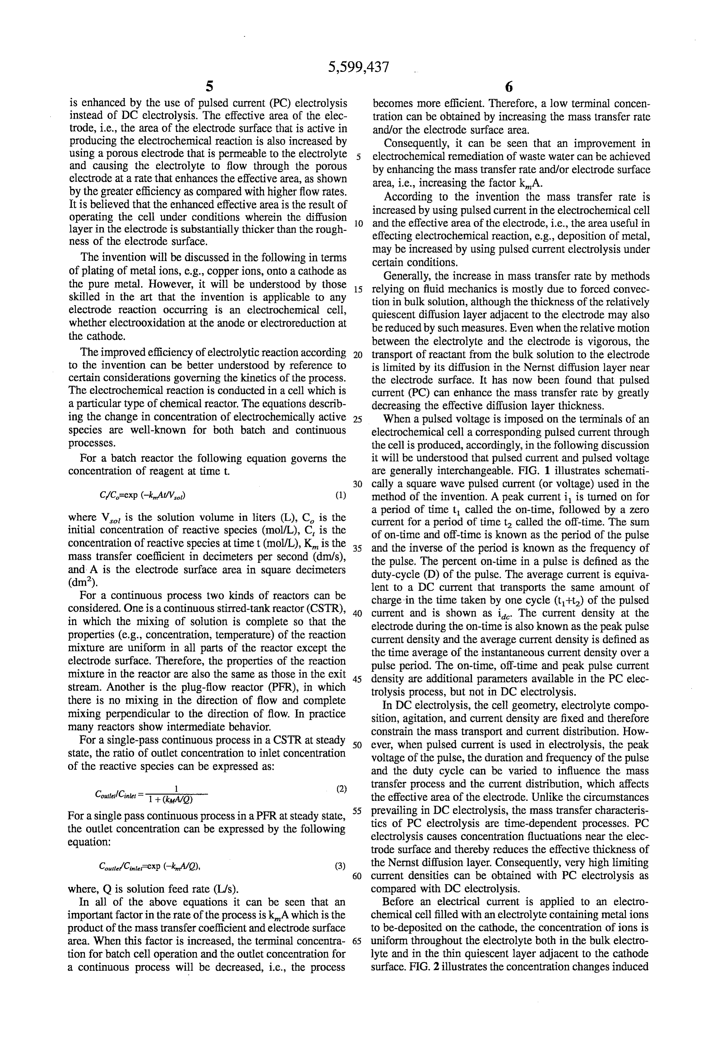
For a single-pass continuous process in a CSTR at steady 50 constrain the mass transport and current distribution. How ever, when pulsed current is used in electrolysis, the peak state, the ratio of outlet concentration to inlet concentration voltage of the pulse, the duration and frequency of the pulse of the reactive species can be expressed as: and the duty cycle can be varied to influence the mass -- (2) transfer process and the current distribution, which affects Coutled Cinlet F 1 + (ka/O) the effective area of the electrode. Unlike the circumstances For a single pass continuous process in a PFR at steady state, prevailing in DC electrolysis, the mass transfer characteris
the outlet concentration can be expressed by the following tics of PC electrolysis are time-dependent processes. PC equation: electrolysis causes concentration fluctuations near the elec trode surface and thereby reduces the effective thickness of
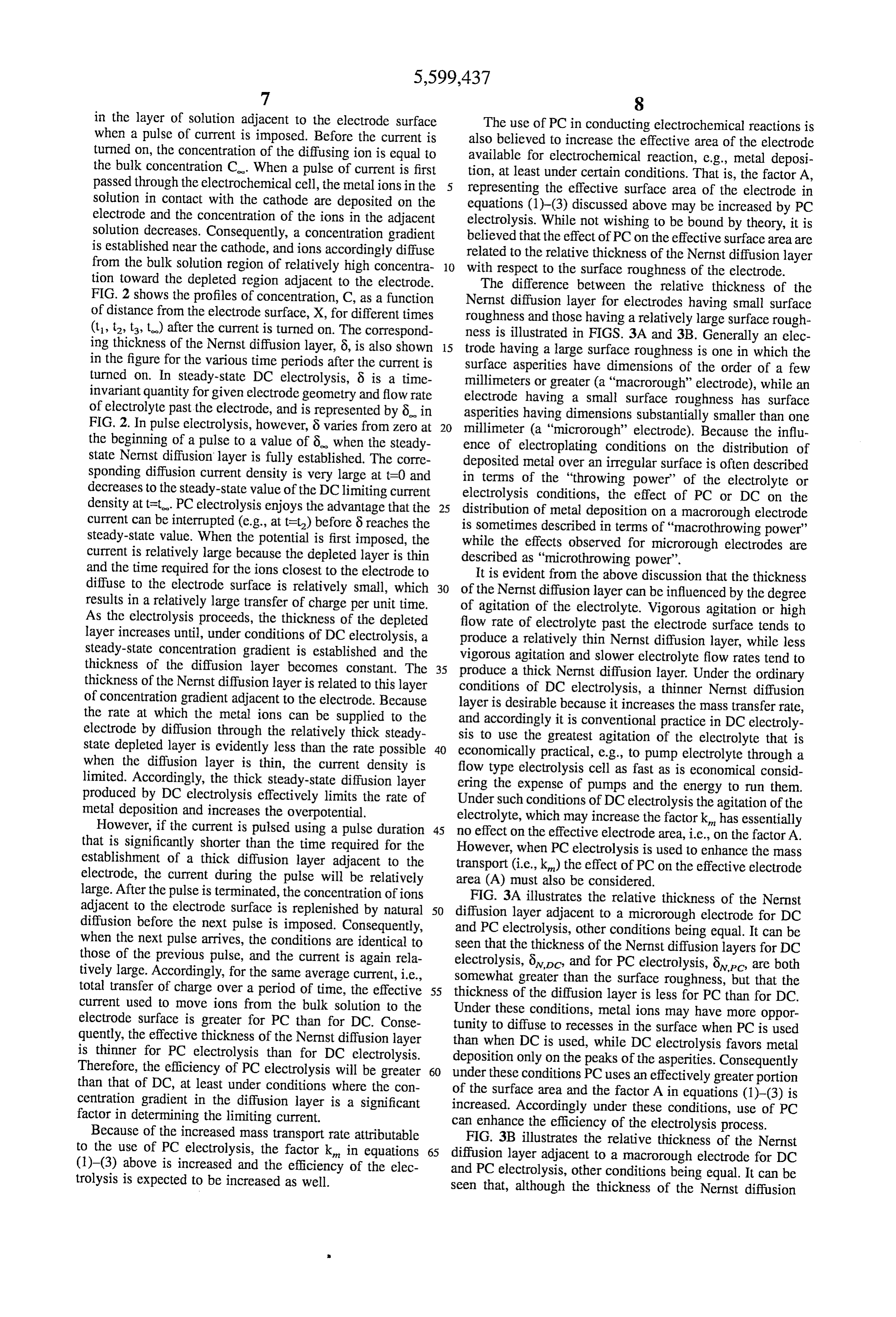
Coutter?Centerexp (-knA/O), (3) the Nernst diffusion layer. Consequently, very high limiting 60 current densities can be obtained with PC electrolysis as where, Q is solution feed rate (L/s). compared with DC electrolysis.
In all of the above equations it can be seen that an Before an electrical current is applied to an electro important factor in the rate of the process is kA which is the chemical cell filled with an electrolyte containing metalions product of the mass transfer coefficient and electrode surface to be-deposited on the cathode, the concentration of ions is area. When this factor is increased, the terminal concentra 65 uniform throughout the electrolyte both in the bulk electro tion for batch cell operation and the outlet concentration for lyte and in the thin quiescent layer adjacent to the cathode a continuous process will be decreased, i.e., the process surface. FIG. 2 illustrates the concentration changes induced
Page 12
in the layer of solution adjacent to the electrode surface The use of PC in conducting electrochemical reactions is when a pulse of current is imposed. Before the current is also believed to increase the effective area of the electrode turned on, the concentration of the diffusing ion is equal to available for electrochemical reaction, e.g., metal deposi the bulk concentration C. When a pulse of current is first tion, at least under certain conditions. That is, the factor A, passed through the electrochemical cell, the metalions in the representing the effective surface area of the electrode in solution in contact with the cathode are deposited on the equations (1)–(3) discussed above may be increased by PC electrode and the concentration of the ions in the adjacent electrolysis. While not wishing to be bound by theory, it is solution decreases. Consequently, a concentration gradient believed that the effect of PC on the effective surface area are is established near the cathode, and ions accordingly diffuse related to the relative thickness of the Nernst diffusion layer from the bulk solution region of relatively high concentra 10 with respect to the surface roughness of the electrode. tion toward the depleted region adjacent to the electrode. The difference between the relative thickness of the FIG. 2 shows the profiles of concentration, C, as a function Nernst diffusion layer for electrodes having small surface of distance from the electrode surface, X, for different times roughness and those having a relatively large surface rough (1, t2, t, t) after the current is turned on. The correspond ness is illustrated in FIGS. 3A and 3B. Generally an elec ing thickness of the Nernst diffusion layer, 8, is also shown 15 trode having a large surface roughness is one in which the in the figure for the various time periods after the current is surface asperities have dimensions of the order of a few turned on. In steady-state DC electrolysis, 8 is a time millimeters or greater (a "macrorough' electrode), while an invariant quantity for given electrode geometry and flow rate electrode having a small surface roughness has surface of electrolyte past the electrode, and is represented by 8 in asperities having dimensions substantially smaller than one FIG. 2. In pulse electrolysis, however, 8 varies from zero at 20 millimeter (a "microrough' electrode). Because the influ the beginning of a pulse to a value of 6 when the steady ence of electroplating conditions on the distribution of state Nernst diffusion layer is fully established. The corre deposited metal over an irregular surface is often described sponding diffusion current density is very large at t=0 and in terms of the “throwing power of the electrolyte or decreases to the steady-state value of the DC limiting current density at t=t. PC electrolysis enjoys the advantage that the 25 electrolysis conditions, the effect of PC or DC on the distribution of metal deposition on a macrorough electrode current can be interrupted (e.g., at t=t) before 8 reaches the is sometimes described in terms of "macrothrowing power' steady-state value. When the potential is first imposed, the while the effects observed for microrough electrodes are current is relatively large because the depleted layer is thin described as "microthrowing power'. and the time required for the ions closest to the electrode to It is evident from the above discussion that the thickness diffuse to the electrode surface is relatively small, which 30 of the Nernst diffusion layer can be influenced by the degree results in a relatively large transfer of charge per unit time. of agitation of the electrolyte. Vigorous agitation or high As the electrolysis proceeds, the thickness of the depleted flow rate of electrolyte past the electrode surface tends to layer increases until, under conditions of DC electrolysis, a steady-state concentration gradient is established and the vigorous aagitation produce relatively thin Nernst diffusion layer, while less and slower electrolyte flow rates tend to thickness of the diffusion layer becomes constant. The 35 produce a thick Nernst diffusion layer. Under the ordinary thickness of the Nernst diffusion layer is related to this layer of concentration gradient adjacent to the electrode. Because conditions layer is of DC electrolysis, a thinner Nernst diffusion desirable because it increases the mass transfer rate, the rate at which the metal ions can be supplied to the and accordingly it is conventional practice in DC electroly electrode by diffusion through the relatively thick steady sis to use the greatest agitation of the electrolyte that is state depleted layer is evidently less than the rate possible 40 economically practical, e.g., to pump electrolyte through a when the diffusion layer is thin, the current density is flow type electrolysis cell as fast as is economical consid limited. Accordingly, the thick steady-state diffusion layer ering the expense of pumps and the energy to run them. produced by DC electrolysis effectively limits the rate of Under such conditions of DC electrolysis the agitation of the metal deposition and increases the overpotential.
However, if the current is pulsed using a pulse duration 45 no effect on the effective electrode area, i.e., onhastheessentially electrolyte, which may increase the factork factor A.
that is significantly shorter than the time required for the However, when PC electrolysis is used to enhance the mass establishment of a thick diffusion layer adjacent to the transport (i.e., k) the effect of PC on the effective electrode electrode, the current during the pulse will be relatively area (A) must also be considered.
large. After the pulse is terminated, the concentration of ions FIG. 3A illustrates the relative thickness of the Nernst adjacent to the electrode surface is replenished by natural 50 diffusion layer adjacent to a microrough electrode for DC diffusion before the next pulse is imposed. Consequently, and PC electrolysis, other conditions being equal. It can be when the next pulse arrives, the conditions are identical to seen that the thickness of the Nernst diffusion layers for DC those of the previous pulse, and the current is again rela electrolysis, 8pc and for PC electrolysis, 8vo, are both tively large. Accordingly, for the same average current, i.e., somewhat greater than the surface roughness, but that the total transfer of charge over a period of time, the effective 55 thickness of the diffusion layer is less for PC than for DC. current used to move ions from the bulk solution to the Under these conditions, metal ions may have more oppor electrode surface is greater for PC than for DC. Conse quently, the effective thickness of the Nernst diffusion layer than when DC istoused, tunity to diffuse recesses in the surface when PC is used while DC electrolysis favors metal is thinner for PC electrolysis than for DC electrolysis. deposition only on the peaks of the asperities. Consequently Therefore, the efficiency of PC electrolysis will be greater under these conditions PC uses an effectively greater portion than that of DC, at least under conditions where the con of the surface area and the factor A in equations (1)–(3) is centration gradient in the diffusion layer is a significant increased. Accordingly under these conditions, use of PC factor in determining the limiting current. can enhance the efficiency of the electrolysis process. Because of the increased mass transport rate attributable FIG. 3B illustrates the relative thickness of the Nernst to the use of PC electrolysis, the factor k in equations 65 diffusion layer adjacent to a macrorough electrode for DC (1)–(3) above is increased and the efficiency of the elec and PC electrolysis, other conditions being equal. It can be trolysis is expected to be increased as well. seen that, although the thickness of the Nernst diffusion
Page 13
layer for PC is again somewhat less than for DC, the change electrodes, about 25% of the electrode would be expected to in thickness is the same for both the peaks and valleys of the be wet by the electrolyte, resulting in an effective roughness electrode surface asperities. Consequently, under these con factor of about 10,000. Such an electrode can be considered ditions, the use of PC is expected to have little effect on the to be an ultra-high surface area electrode, and would be distribution of the metalions over the electrode surface, i.e., expected to act as a microrough electrode because the the effective electrode area for PC would be no greater than packed particles are very small, and the electrode can be that for DC. Furthermore, because PC uniformly decreases operated under conditions wherein the particle size is very the polarization resistance due to the ion-depleted layer small compared to the thickness of the Nernst diffusion adjacent to the electrode, the current distribution under PC layer. Packed-bed electrodes useful in practicing the method conditions would be expected to favor the peaks of the 10 of the invention can be prepared using carbon particles electrode surface asperities. Consequently, under such con having an average diameter of about 1 mm. Such electrodes ditions, the use of PC might actually decrease the effective can also be prepared using carbon particles having a specific area A of the electrode. surface area of at leat 80 m/g, preferably at least 750 m?g. It is according to the invention to operate an electrolytic In some cases carbon particles having a specific surface area cell, e.g., a cell for removing metals from waste solutions, 15 of not less than about 1500 m/g may be used in preparing under conditions wherein the use of PC provides an increase packed-bed electrodes for use in the process of the inven in the efficiency of the electrolysis with respect to DC. The tion. When PC electrolysis is used in conjunction with such frequency of the pulses should be low enough and the duty high surface are electrodes, the factor kA is greatly cycle should be great enough to complete the two-step increased due to the enhanced mass transfer rate and the copper reductionprocess, i.e., reduction of copper (II) to 20 relatively great proportion of the electrode surface area that copper (I) and reduction of copper (I) to metallic copper. is utilized.
Moreover, the frequency should be high enough and the duty A further enhancement of the mass transfer rate is pos cycle should be low enough to enhance the mass transfer sible with such high surface are electrodes by employing a rate. One skilled in the art, instructed by the above discus coating of an ion exchange resin on the electrode particles. sion, will have no difficulty in determining the best balance 25 Any ion exchange resin capable of binding metal ions is of pulse frequency, pulse width and duty cycle. for a given usable to coat the electrode. A suitable coated electrode for process and electrolytic cell. In most practical cases, the use in the method of the invention is a high surface area pulse frequency will range from 0.5 Hz to 1000 Hz and the electrode, e.g., a packed bed of carbon particles, wherein the duty cycle will not exceed 50%. Preferably the pulse fre particles have been coated with a thin layer of a perfluori quency will be between about 10 Hz and 100 Hz, and the 30 nated sulfonic acidionomer such as that sold by E. I. duPont duty cycle will be between 10% and 50%. de Nemours & Co. under the trade name Nafion(E). The In order to provide a microrough electrode which favors carbon to be made into the electrode is coated by the the use of PC electrolysis, as explained above, it is advan conventional process of immersing the carbon particles in a tageous to use electrodes having as high a surface area as solution of such an ion exchange resin in a suitable solvent practically possible. Although such high surface area elec 35 and then removing them from the solution and allowing the trodes can be prepared from large plates or plates arranged coated particles to dry. The carbon particles can then be in arrays, e.g., closely spaced arrays, high surface area made into a high surface area electrode by conventional electrodes useful in the process of the invention are typically procedures as described above. The presence of a layer of prepared from a porous material or by means of packed bed ion exchange resin on the surface of the electrode provides of conductive particles. Such electrodes are sometimes 40 a method of enhancing the concentration of electroactive referred as "fuel cell type electrodes' because they are species, e.g., metal ions, adjacent to the electrode surface frequently used in such cells. Such high surface area fuel cell and thereby increasing the mass transfer rate. type electrodes offer the potential for roughness factors of up The practice of the invention is illustrated by the follow to 10,000 or more, i.e., the ratio of total surface area of the ing examples which are intended to be illustrative only and porous electrode to the projected or geometric area pre 45 do not limit the scope of the invention in any way. In the sented to the cell. Such fuel cell electrodes may comprise, examples comparative experiments were conducted to for example, a noble metal catalyst supported on a high recover copper from an acid copper sulfate solution using specific surface area carbon (750 m/g). The carbon/catalyst PC electrolysis, with DC electrolysis as a baseline. composite is bonded into a massive electrode by a fluoro The experimental apparatus comprised an electrolytic cell carbon polymer matrix, e.g., polytetrafluoroethylene or flu 50 as illustrated in FIG. 4 and associated tanks and pumps for orinated ethylene-propylene copolymer, and pressed onto a circulating electrolyte and an electrical power supply current collector made from a carbon fiber paper material. together with metering equipment to monitor and record The content of fluorinated polymer and the processing current and voltage.
temperature are adjusted to achieve optimum balance The cell comprised three cell modules of the type illus between liquid wetting and gas intrusion. The manufacture 55 trated schematically in FIG. 4. Each module comprised an of such electrodes is known to those skilled in the art and is enclosure 402 containing a cathode 404, an anode 406 and discussed, for example, in Giordano, N., et al., Electro a membrane 408 that divided the module onto a cathode chimica Acta 35 (9), p. 1411 (1990). compartment 410 and an anode compartment 412. The For removing metals from waste solutions, a similar membrane was positioned as close as possible to the packed electrode can be prepared using carbon containing no cata 60 bed cathode 404, and the anode 406 was spaced about 2.5 lyst and adjusting the content of fluorinated polymer and mm from the membrane. The membrane was made of processing temperature to achieve maximum wettability of fluorinated ionomeric polymer, Na?ion(9450, sold by E. I du the carbon cathode with the waste solution containing a low Pont de Nemours & Co. A catholyte inlet 414 and a catholyte concentration of metal ion. Typically such a high surface outlet 416 are provided for cirulating the catholyte from a area cathode will contain about 5 mg/cm of material 65 catholyte tank not shown through the cathode compartment resulting in about 40,000 cm of carbon per cm of elec 410 and back to the catholyte tank. Similarly, an anolyte trode. Based on experience with conventional gas diffusion inlet 418 and an anolyte outlet 420 are provided for ciru
Page 14
lating the anolyte from an anolyte tank, not shown, through temperatures varied from 70° to 74° F (22.8° C. to 32.9° C.) the anode compartment 412 and back to the anolyte tank. A and the pH of both electrolytes was about 2.2. cathode terminal 422 and an anode terminal 424 are pro FIG. 5 shows the change in copper ion concentration with vided for supplying the electrolysis current to the cell and electrolysis time for a DC test of 10 A and several PC tests were connected to sources of pulsed or direct current as having an average cell current (I) of 10 A, a frequency of appropriate for the experimental conditions under investi 10 Hz and different duty cycles (D). A comparison of the gation. The cathode 404 was a packed-bed cathode which plots in the figure shows that all of the PC runs took less time was packed with irregular graphite particles having an equivalent diameter of 1-2 mm. The void fraction was about to deplete the copper ion concentration in the catholyte from 0.5. The cathode had a vertical height of 25 cm, a width of 10 about 200 ppm to 1 ppm. FIGS. 6 and 7 show the instan 16 cm and the thickness of the packed bed was 9 mm. taneous cathodic current efficiency and electrical energy Catholyte entered the bottom of the cell through inlet 414, consumption, respectively, per kilogram of copper recov flowed through the cathode in an upward direction, and ered vs. copper concentration for these runs. As shown in the exited the cell at outlet 416 at the top of the cell. The anode figures, current efficiency was higher and energy consump 406 was a specially constructed metal mesh anode coated 15 tion was lower for all PC electrolysis compared to DC with a titanium-ruthenium oxide coating to provide low electrolysis.
oxygen overvoltage and generally known in the art as a Further results for tests using the same test cell operated dimensionally stable anode (sold, for example, by Diamond at a catholyte and anolyte flow rate of 0.5 L/min are shown Shamrock, S. A. under the trademark DSA). The experi in FIGS. 8, 9 and 10. FIG. 8 shows the copper concentration ments were conducted in a batchwise recirculation mode. 20 change with electrolysis time for a DC test at 20 A and Catholyte and anolyte were recirculated between their several PC tests with an average cell current of 10A. It can respective holding tanks and the cathode or anode compart be seen that it took almost the same time for DC at 20 A and ments of the electrochemical cell at a preselected flow rate. all PC runs with an average current of 10 A to decrease During the experiment, the pH and temperature of the catholyte and anolyte were measured and the cathode-to 25 to copper concentration from 200 ppm to 1 ppm. However, due anode voltage was monitored with a voltmeter. the high cathode-to-anode voltage at DC 20 A, the energy To examine the effect of pulsed current (PC) on copper consumption per kilogram of copper recovered was much recovery process, PC with varied frequencies, duty cycles higher for DC 20 A than for the PC runs. FIGS. 9 and 10 and peak currents were used in the tests at three different show the instantaneous cathodic current efficiency and elec solution flow rates of 0.5 liters/minute, 2.5 L/min and 6 30 trical energy consumption, respectively, per kilogram of L/min, and the results were compared to DC electrolysis at copper recovered vs. copper concentration for these runs. As the same average cell current. From experimental results, it shown in the figures, current efficiency was much higher and was found that PC had a different effect at different solution energy consumption was much lower for all PC electrolysis flow rates. compared to DC electrolysis. Table 1 below summarizes the 35 average current efficiency and energy consumption per kilo gram of copper recovered for DC of 10 A and 20 A, and PC
EXAMPLE 1 runs with an average current of 10 A. The average current efficiency and energy consumption are based on a copper
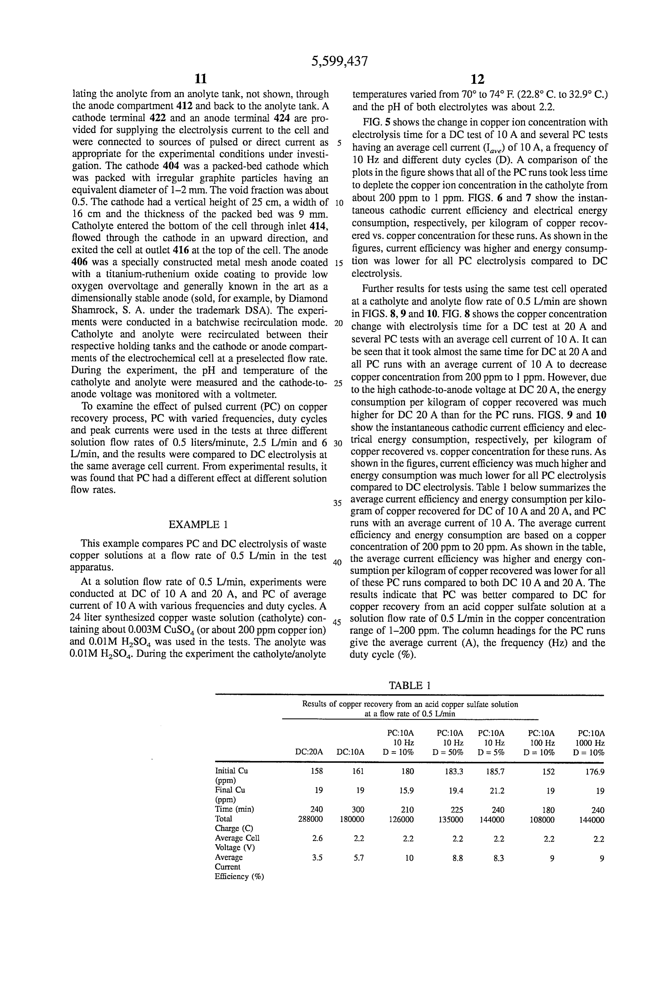
This example compares PC and DC electrolysis of waste concentration of 200 ppm to 20 ppm. As shown in the table, copper solutions at a flow rate of 0.5 L/min in the test 40 the average current efficiency was higher and energy con apparatus. sumption per kilogram of copper recovered was lower for all At a solution flow rate of 0.5 L/min, experiments were of these PC runs compared to both DC 10 A and 20A. The conducted at DC of 10 A and 20 A, and PC of average results indicate that PC was better compared to DC for current of 10 A with various frequencies and duty cycles. A copper recovery from an acid copper sulfate solution at a 24 liter synthesized copper waste solution (catholyte) con 45 solution flow rate of 0.5 L/min in the copper concentration taining about 0.003M CuSO4 (or about 200 ppm copperion) range of 1-200 ppm. The column headings for the PC runs and 0.01M HSO was used in the tests. The anolyte was give the average current (A), the frequency (Hz) and the 0.01M H2SO4. During the experiment the catholyte/anolyte duty cycle (%).
TABLE
Results of copper recovery from an acid copper sulfate solution at a flow rate of 0.5 L/min
DC:20A DC-10A D at 10% D = 50% D = 5% D at 10% D = 10%
Initial Cu 158 16 180 183.3 185.7 152 176.9 (ppm)
Final Cu 19 19 15.9 19.4 21.2 19 19 (ppm)
Time (min) 240 300 210 225 240 180 240 Total 288000 180000 126000 135000 144000 108000 144000 Charge (C)
Average Cell 2.6 2.2 2.2 2.2 2.2 2.2 2.2 Voltage (V)
Average 3.5 5.7 10 8.8 8.3 9 9 Current
Efficiency (%)
Page 15
TABLE 1-continued
Results of copper recovery from an acid copper sulfate solution at a flow rate of 0.5 L/min
DC:2OA DCOA D = 10% D = 50% D = 5% as 10% D = 10%
Average 62.7 32.6 18.6 21.1 22.3 20.6 23.2 Enpion
EXAMPLE 2 15 flow rate. These results indicated that DC was better than PC This example compares PC and DC electrolysis of waste Sp R.E. typiction at copper solutions at a flow rate of 2.5 L/min in the test apparatus.
At a solution flow rate of 2.5 L/min, experiments were conducted at DC of 20 A, and PC of average current of 2020 EXAMPLE 4 A with various frequencies and duty cycles. A 24 liter This example compares the efficiency of copper recovery synthesized copper waste solution (catholyte) containing about 0.012M CuSO(or about 800 ppm copper ion) and for PC and DC under the best conditions for each mode in 0.01M HSO was used in the tests. The anolyte was 0.01M the experimental cell.
HSO. During the experiment the catholyte/anolyte tem- ? Copper solutions containing 1000 ppm of CU (II) were peratures varied from 70° to 74° F (22.8° C. to 32.9° C) and prepared and electrolyzed by the general procedure of the pH of both electrolytes was about 2.2. Example 1 using the test electrolysis cell described above FIG. 11 shows the change in copper ion concentration with an average current of 40A for PC and a steady current with electrolysis time for a DC test of 20A and several PC of 40 A for DC. Five different flow rates were tested, 0.5
or line plots in the figure Snows that 1t took almost the same
L/min, 2.5o L/min 6 a L/min, 8.5 L/min and 10 L/min. The length of time for DC and all of the PC runs to deplete the mission findigentions le copper ion concentration in the catholyte from about 800 ppm to 1 ppm. The average cathode-to-anode voltages for The most efficient conditions for metal removal using PC DC of 20 Aand PC of average current of 20A are almost the were found to be an electrolyte flow rate of 0.5 L/min, a same. The current efficiency and energy consumption per frequency of 10 Hz and a duty cycle of 10%. FIG. 13 kilogram of copper recovered for both cases at 2.5 L/min are compares the rate of removal of metalions from the solution also comparable. These results indicated that PC had no for PC and DC at an average current of 40 A for the best improvement compared to DC for copper recovery from an 40 conditions for each mode. The results show that even at a acid copper sulfate solution at a solution flow rate of 2.5 flow rate of 0.5 L/min the PC electrolysis reduces the L/min in the test apparatus. concentration of the solution substantially faster than DC electrolysis and reaches lower ultimate concentrations in a
EXAMPLE 3 substantially shorter time. The PC electrolysis was able to 45 reduce the metalion concentration to 1 ppm in less than 60
This example compares PC and DC electrolysis of waste min, while the DC electrolysis reached only about 6-7ppm copper solutions at a flow rate of 6 L/min in the test and took 90 min to reach that value. FIG. 14 compares the apparatus. current efficiency for the PC and DC processes in the At a solution flow rate of 6 L/min, experiments were experiments of this example. FIG. 14 shows that the current conducted at DC of 20A, and PC of average current of 20 50 efficiency for PC at its best conditions (0.5 L/min flow rate, A with various frequencies and duty cycles. A 24 liter 40A average current, 10 Hz frequency, and 10% duty cycle) synthesized copper waste solution (catholyte) containing is substantially greater than the current efficiency of DC about 0.012M CuSO, (or about 800 ppm copper ion) and electrolysis at its best conditions (6 L/min flow rate, 40 A 0.0MHSO, was used in the tests. The anolyte was 0.01M average current) for all concentrations of copper in the HSO4. During the experiment the catholytefanolyte tem- 55 electrolyte solution
the pH of both electrolytes was about 2.2.
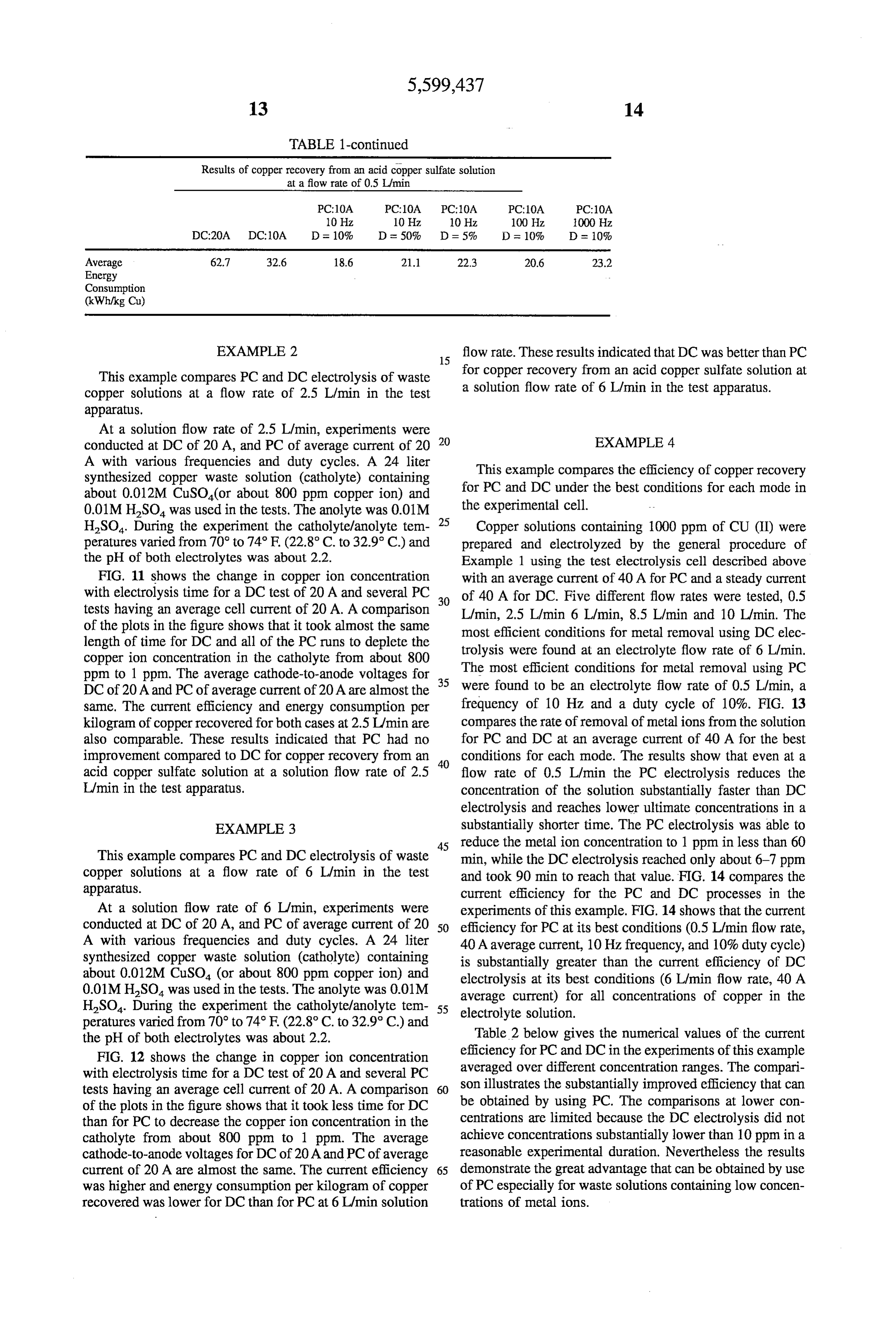
Table 2 below gives the numerical values of the current 12 shows the A. in copper ion concentration efficiency for PC and DC in the experiments of this example with electrolysis time for a DC test of 20 A and several PC averaged over different concentration ranges. The comparl tests having an average cell current of 20 A. A comparison 60 son illustrates the Substantially improved efficiency that can of the plots in the figure shows that it took less time for DC be obtained by using PC. The comparisons at lower con than for PC to decrease the copperion concentration in the centrations are limited because the DC electrolysis did not catholyte from about 800 ppm to 1 ppm. The average achieve concentrations substantially lower than 10 ppm in a cathode-to-anode voltages for DC of 20A and PC of average reasonable experimental duration. Nevertheless the results current of 20 A are almost the same. The current efficiency 65 demonstrate the great advantage that can be obtained by use was higher and energy consumption per kilogram of copper of PC especially for waste solutions containing low concen recovered was lower for DC than for PC at 6 L/min solution trations of metal ions.
Page 16
species undergoes an electrochemical reaction at one of
TABLE 2 said cathode or said anode at an electrochemical reac Current Efficiency for Pulsed Current and Direct Current tion rate, wherein said electric current is a pulsed Electrowinning under Best Conditions at 40A Average current pulsed at a frequency of about 0.5 to about 1000 Current Hertz and having a duty cycle of not greater than about Current Efficiency (%)
adjusting said electrolyte flow rate that said electrochemi
Concentration
Pulsed Current
cal reaction rate when said current is pulsed current is
Range (ppm) duty cycle 10%) (6 L/min) greater than said electrochemical reaction rate to main tain microthrowing power effect wherein kA for elec 000-500 95 80 trolysis using said pulsed current exceeds said kA for
electrolysis using direct current.
1000-50 70 35 2. The method of claim 1 wherein said pulsed current 1000-10 60 20 electrolyte flow rate is less than an electrolyte flow rate 1000-1 55 15 which produces the same electrochemical reaction rate when 500-10 15 said electric current is direct current.
200-10 10 3. The method of claim 1 wherein said cathode is a high 200- 40 surface area electrode.
100-10 8 4. The method of claim 1 wherein said cathode is a 100-1 25 20 packed-bed electrode.
50- 20 5. The method of claim 4 wherein said cathode is a packed bed electrode containing carbon particles of average diam eter no greater than about 1 millimeter.
The results of this example, as illustrated in FIGS. 13 and 6. The method of claim 4 wherein said cathode is a packed 14 and in Table 2, demonstrate that PC electrolysis can bed electrode containing carbon particles having a specific provide very significant advantages in the electroremedia surface area of at least about 80 m/g. tion of waste solutions containing metal ions as compared 7. The method of claim 4 wherein said cathode is a with DC electrolysis. packed-bed cathode containing carbon particles having a The results of the experiments described above illustrate specific surface area of at least about 750 m/g. that it is possible to achieve an increased efficiency of the 30 8. The method of claim 4 wherein said cathode is a electroplating process in removing metals from waste solu packed-bed cathode containing carbon particles having a tions to the very low levels required by current regulations specific surface area of at least about 1500 m/g. governing release of waste solutions to the environment. The 9. The method of claim 1 wherein said electrode has a results show that this increased efficiency is obtained by roughness factor of at least about 10,000. operating the electrochemical cell using PC electrolysis and 35 10. The method of claim 1 wherein said frequency is from restricting the flow rate of electrolyte through the electrode about 10 Hz to about 100 Hz.
so that the electrode is operating under microrough condi 11. The method of claim 1 wherein said duty cycle is from tions. Such improved efficiency can, of course, result in a about 10% to about 50%.
lowered expenditure of energy for purifying waste solutions 12. The method of claim wherein said frequency is from by electrolysis. The improved efficiency can also allow the 40 about 10 Hz to about 100 Hz and said duty cycle is from use of smaller and less expensive electrolytic cells with the about 10% to about 50%.
accompanying substantial decrease in capital expenditure 13. A method for removing metal ions from waste solu for pollution control equipment in those industries which tions by electrolytic deposition comprising must remediate their metal-containing waste solutions to introducing an electrolyte containing ions of a metal into very low levels of contaminants. 45 an electrolytic cell having a cathode and an anode,
The invention having now been fully described, it should producing a flow of said electrolyte past at least one of be understood that it may be embodied in other specific said cathode or said anode at an electrolyte flow rate, forms or variations without departing from its spirit or passing an electric current through said solution between essential characteristics. Accordingly, the embodiments 50 said anode and said cathode whereby said ions are described above are to be considered in all respects as deposited as elemental metal on said cathode at an illustrative and not restrictive, the scope of the invention electrodeposition rate, wherein said electric current is being indicated by the appended claims rather than the pulsed current pulsed at a frequency of about 0.5 to foregoing description, and all changes which come within about 1000 Hertz and a duty cycle of not greater than the meaning and range of equivalency of the claims are 55 about 50%, and intended to be embraced therein.
We claim: adjusting said electrolyte flow rate to maintain micro 1. A method for producing an electrochemical reaction at throwing power effect wherein kA for electrolysis an electrode in contact with a solution of an electroactive using said pulsed current exceeds said kA for elec species comprising trolysis using direct current. introducing an electrolyte containing an electroactive 60 14. The method of claim 13 wherein said pulsed current species into an electrolytic cell having a cathode and an electrolyte flow rate is less than an electrolyte flow rate anode, which produces the same electrodeposition rate when said electric current is direct current.
producing a flow of said electrolyte past at least one of 15. The method of claim 13 wherein said cathode is a high said cathode or said anode at an electrolyte flow rate, 65 Surface area electrode.
passing an electric current through said solution between 16. The method of claim 15 wherein said cathode is a said anode and said cathode whereby said electroactive packed-bed cathode.
Page 17
17. The method of claim 15 wherein said cathode is a 23. The method of claim 13 wherein said duty cycle is packed bed electrode containing carbon particles of average from about 10% to about 50%.
diameter no greater than about 1 millimeter. 24. The method of claim 13 wherein said frequency is 18. The method of claim 15 wherein said cathode is a from about 10 Hz to about 100 Hz and said duty cycle is packed bed electrode containing carbon particles having a from about 10% to about 50%.
specific surface area of at least about 80 m/g. 25. The method of claim 13 wherein said metal is selected 19. The method of claim 15 wherein said cathode is a packed-bed cathode containing carbon particles having a from the group consisting of copper, silver, gold, zinc, specific surface area of at least about 750 m?g. nickel, mercury, lead, uranium, cadmium and chromium. 20. The method of claim 15 wherein said cathode is a 10 26. The method of claim 13 wherein said cathode com packed-bed cathode containing carbon particles having a prises a packed bed of a particulate conducting material, said specific surface area of at least about 1500 m/g. particulate material being coated with an ion exchange resin. 2. The method of claim 15 wherein said electrode has a 27. The method of claim 26 wherein said ion exchange roughness factor of at least about 10,000. resin is a perfluorinated sulfonic acid ionomer resin. 22. The method of claim 13 wherein said frequency is 5 from about 10 Hz to about 100 Hz. ck k k k sk
Provenance
- Collection
- Cited prior art
- Original PDF
- patentimages.storage.googleapis.com →
- Filed
- 1995-06-20
- Pages
- 17
- Method
- pdftotext (the PDF's own text layer) + pdftoppm 300dpi page scans
- Source
- Google Patents bibliographic record
- Granted
- 1997-02-04
- Inventors
- E. Jennings Taylor; Chengdong Zhou; Robert P. Renz; Mahendra K. Sunkara; Faraday Technology Inc
- Transcribed from
- patentimages.storage.googleapis.com →