patent · US4382849
Apparatus for electrolysis using gas and electrolyte channeling to reduce shunt currents
10 May 1983
Page 1 — bibliographic record
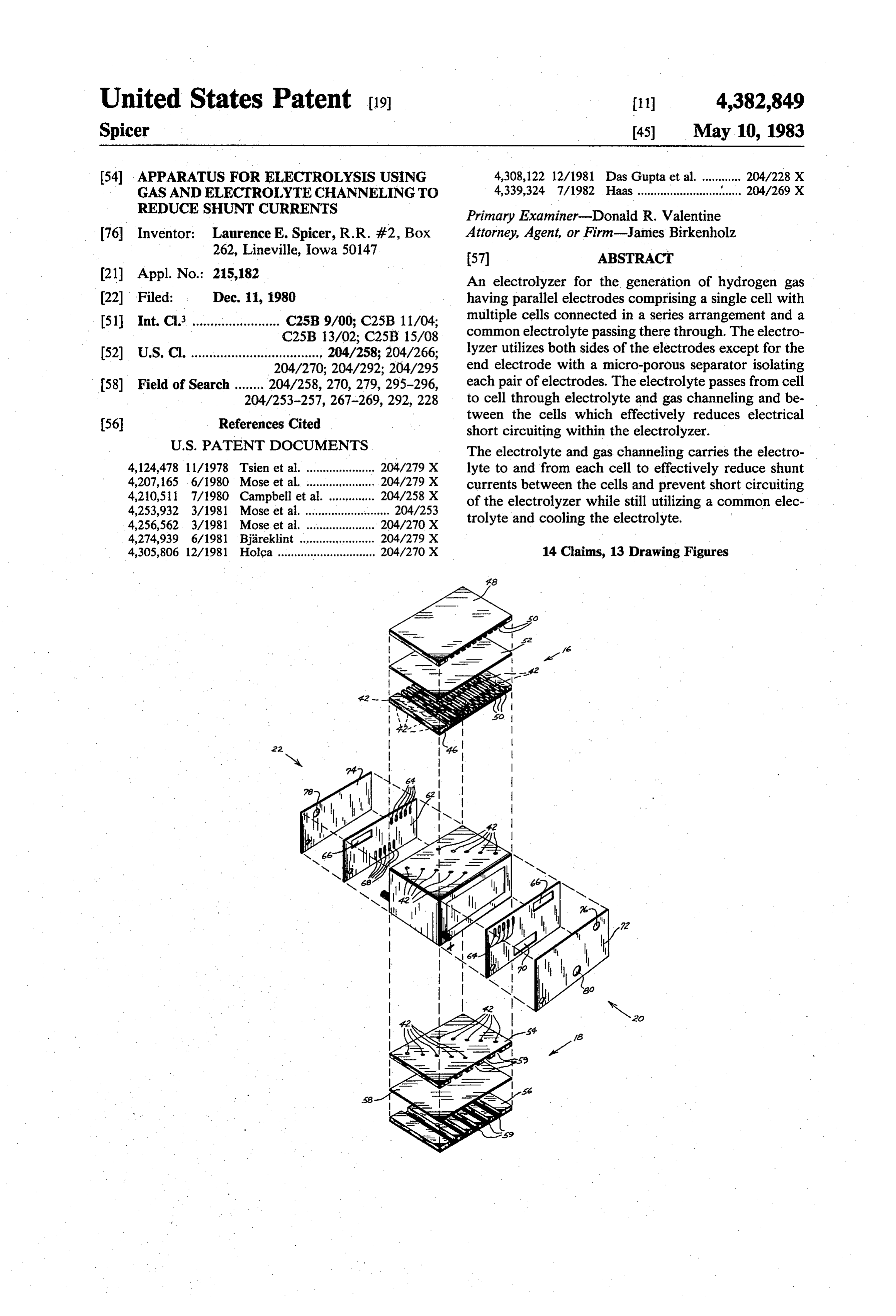
United States Patent (19) (11) 4,382,849 Spicer 45) May 10, 1983 54 APPARATUS FOR ELECTROLYSIS USING 4,308,122 12/1981 Das Gupta et al. ............ 204/228 X GAS AND ELECTROLYTE CHANNELING TO 4,339,324 7/1982 Haas................................ 204/269 X
REDUCE SHUNT CURRENTS
Primary Examiner-Donald R. Valentine 76) Inventor: Laurence E. Spicer, R.R. #2, Box Attorney, Agent, or Firm-James Birkenholz 262, Lineville, Iowa 50147 57 ABSTRACT (21) Appl. No.: 215,182 An electrolyzer for the generation of hydrogen gas 22 Filed: Dec. 11, 1980 having parallel electrodes comprising a single cell with (51) Int. C. ........ ... . . . . . . . . . . . . . C25B 9/00; C25B 11/04; multiple cells connected in a series arrangement and a C25B 13/02; C25B 15/08 common electrolyte passing there through. The electro (52) U.S. C. ................................... . 204/258; 204/266; lyzer utilizes both sides of the electrodes except for the 204/270; 204/292; 204/295 end electrode with a micro-porous separator isolating 58) Field of Search ......., 204/258, 270, 279, 295-296, each pair of electrodes. The electrolyte passes from cell 204/253-257, 267-269,292, 228 to cell through electrolyte and gas channeling and be tween the cells, which effectively reduces electrical 56 References Cited short circuiting within the electrolyzer.
4,124,478 11/1978 Tsien et al. ..................... 204/279 X lyte to and from each cell to effectively reduce shunt 4,207,165 6/1980 Mose et al. .... ... 204/279 X currents between the cells and prevent short circuiting 4,210,511 7/1980 Campbell et al. . . . 204/258 X of the electrolyzer while still utilizing a common elec 4,253,932 3/1981 Mose et al. .......................... 204/253 trolyte and cooling the electrolyte. 4,256,562 3/1981 Mose et al. .... ... 204/270 X 4,274,939 6/1981 Bjareklint .. ... 204/279 X 4,305,806 12/1981 Holca .............................. 204/27O X 14 Claims, 13 Drawing Figures
Page 2
Drawing sheet — no readable text.
Page 3
Drawing sheet — no readable text.
Page 4
Drawing sheet — no readable text.
Page 5
Drawing sheet — no readable text.
Page 6
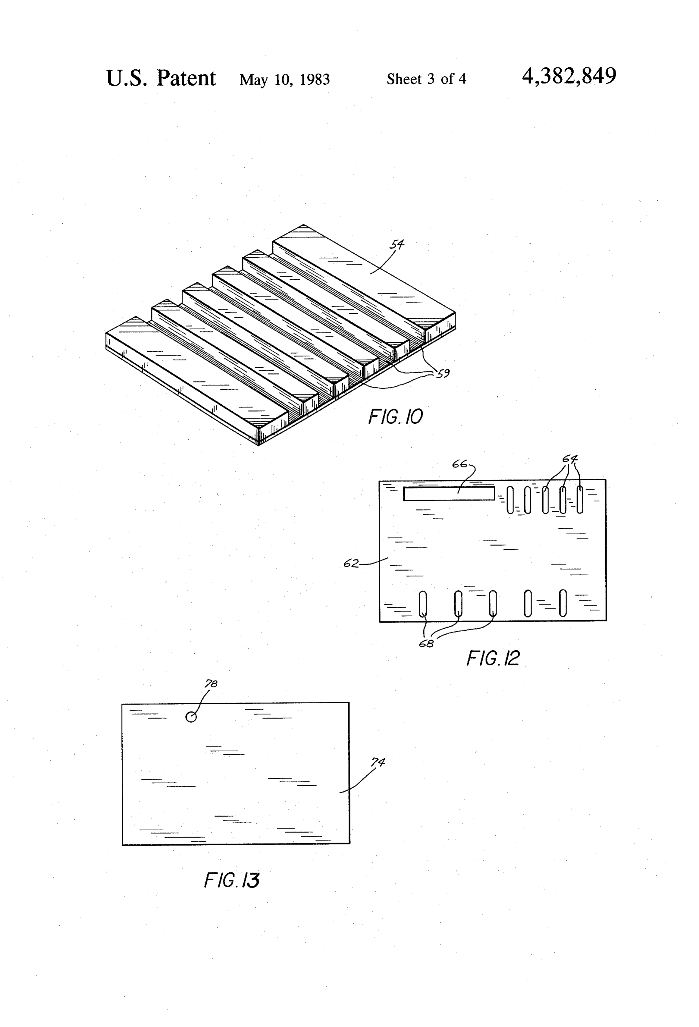
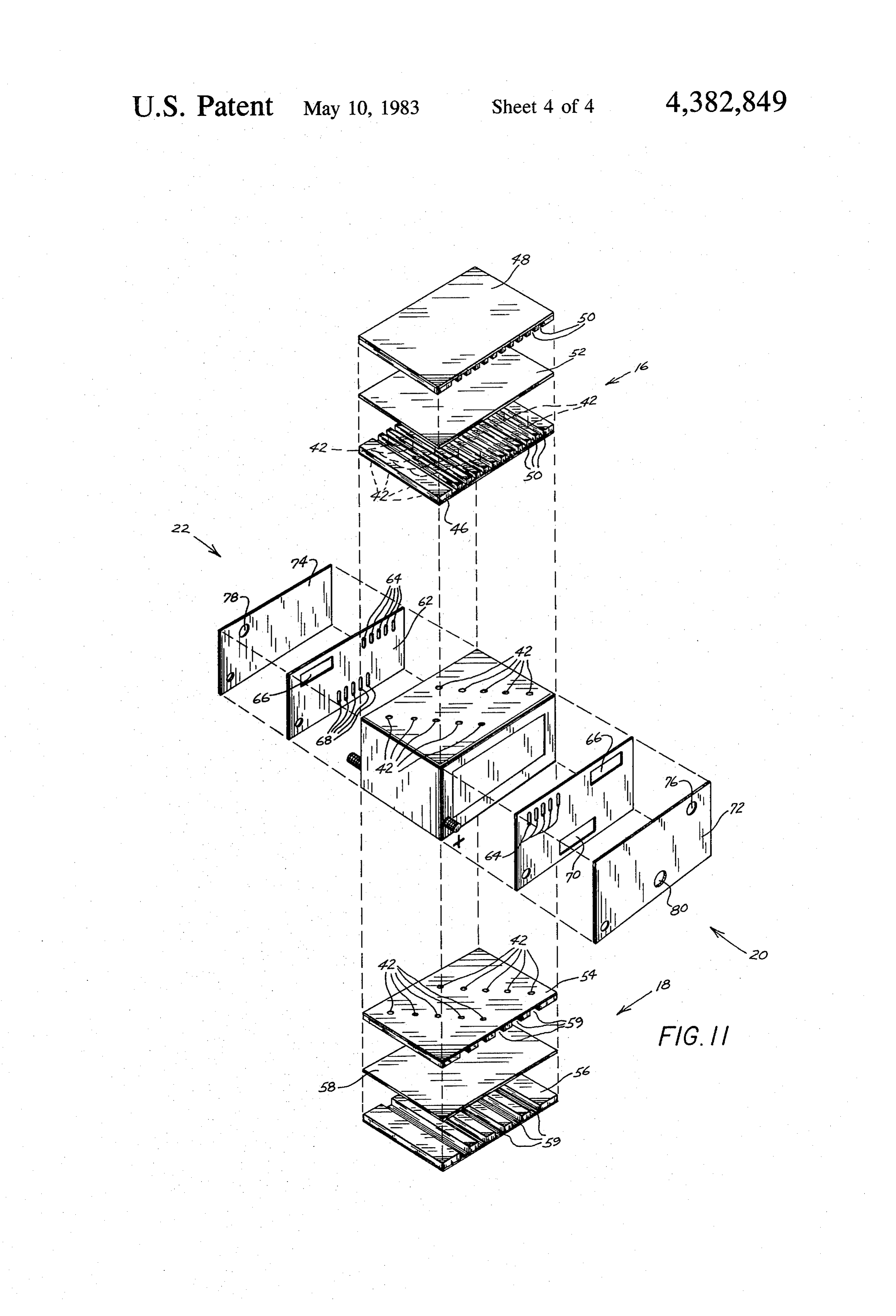
FIG. 11 is a perspective exploded view of the gas and
APPARATUS FOR ELECTROLYSIS USING GAS electrolyte plates and the oxygen and hydrogen collect AND ELECTROLYTE CHANNELNG TO REDUCE ing and cover plates;
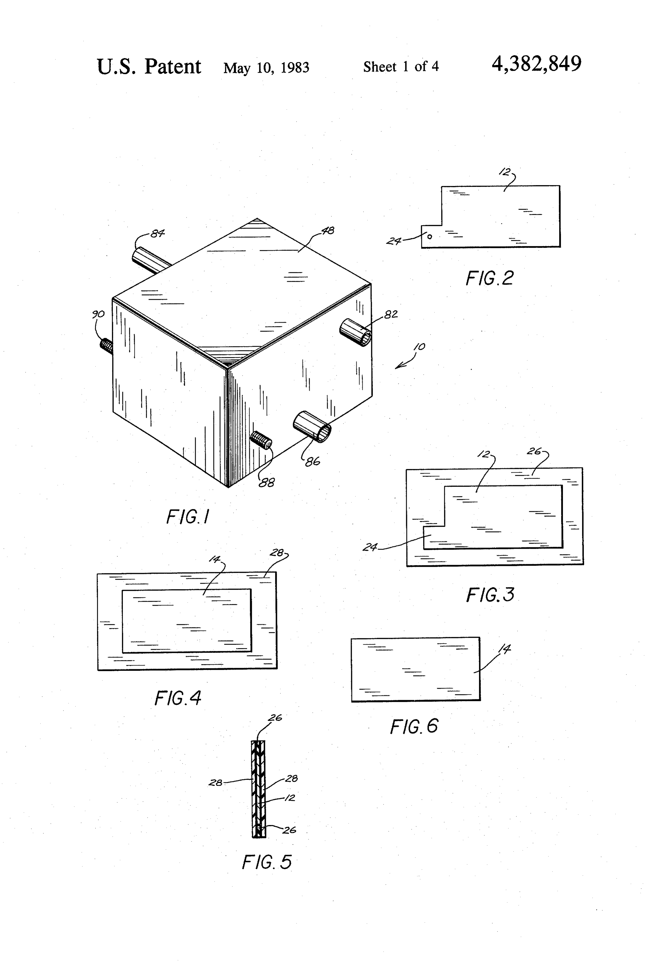
SHUNT CURRENTS '' . FIG. 12 is a side view of the hydrogen collection plate; and
BACKGROUND OF INVENTION FIG. 13 is a side view of the hydrogen cover plate. 1. Field of the Invention DESCRIPTION OF THE PREFERRED The present invention relates to electrolytic cells for EMBODIMENT the generation of gas and particularly to an improved O Referring now to the drawings wherein like refer electrolytic cell wherein gas and electrolyte channeling ence numerals designated identical or corresponding ishaving utilized to reduce shunt currents between cells and parts throughout the several views, FIG. 1 illustrates an electrode arrangement permitting a majority the electrolyzer unit 10 of the present invention. of both sides of the electrode to be used. Generally, the electrolyzer unit 10 includes a plural 2. Description of the Prior Art 15 ity of electrodes 12 (FIGS. 2, 5, 7 and 8, 11), micropo The electrolysis process is frequently employed in rous dividers 14 positioned between the electrodes 12 devices for the generation of gasses by a decomposition with gas plates 16 positioned on the top of the elec process wherein multiple electrodes are immersed in an trodes and electrolyte plates 18 positioned on the bot electrically conductive electrolyte with an electrical tom with oxygen end plates 20 on one end of the unit 10 charge running between the electrodes. The volume of 20 and a hydrogen end plates 22 on the opposite end of the gas produced is in part dependent upon the exposed unit 10.
surface area of the electrodes to the electrolyte. In Specifically the electrodes 12 as illustrated in FIG. 2 order to generate large volumes of gas, electrodes large are made from sintered nickel. The sintered nickel pro physical dimensions or a large number of electrodes vides a large exposed surface area compared with rela must be used, thus greatly increasing the physical di 25 tively small physical dimensions for the electrode 12. mensions of the electrolyzer. An electrode is generally rectangular shape with a elec Isolation of shunt currents between the individual trode tab 24 extending out from the electrode 12 onto cells within the electrolyzer is also a problem. One may which an electrical connection to a source of energy method frequently employed utilizes a metal plate for 30 framebe26made. The electrode 12 is placed in an electrode (FIG. 3) with electrode retaining frames 28 isolation, however, this approach further limits the use (FIG. 4) spaced on both sides of the electrode frame 26 able surface area of the electrodes and in some cases housing the electrode 12 (FIG. 5). limits electrode surface area to only one side of each The micro-porous divider 14 (FIG. 6) is constructed electrode. Further the weight of the electrolyzer would of porous material which will allow flow of electrical be significantly increased, which is an undesireable 35 charge therethrough while still prohibiting gasses such result. as hydrogen and oxygen from passing through. The SUMMARY OF THE INVENTION supporting structure (FIG. 7) of the micro-porous di vider 14 is similar to that previously described for the
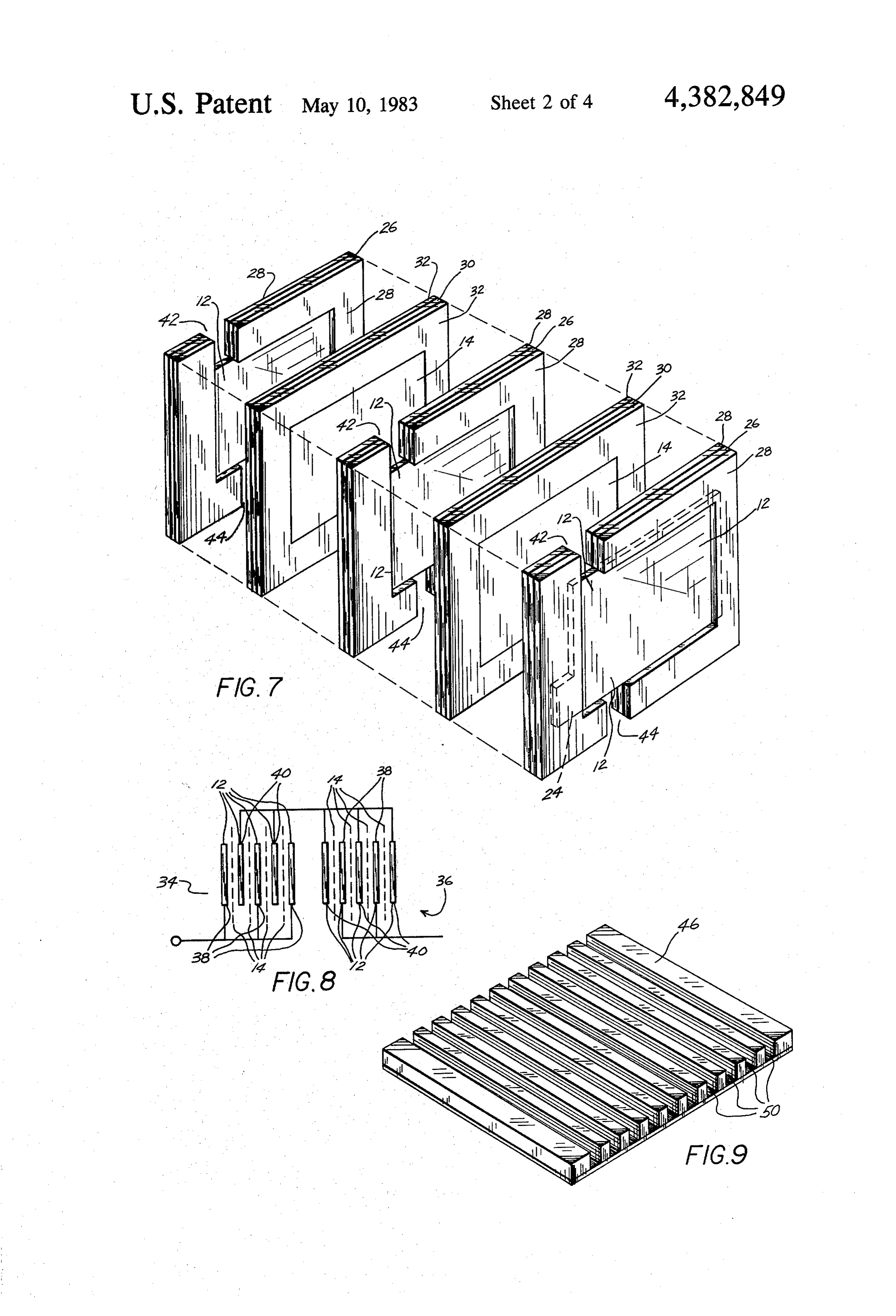
An electrolyzer wherein multiple electrodes are ar electrodes 12 and includes a micro-porous divider frame ranged and electrically connected parallel to each other 40 30 with micro-porous divider retaining frames 32 on to form a cell. Multiple cells are series connected with both sides of the micro-porous divider frame 30. a common electrolyte circulated between the cells. The In constructing the electrode assembly (FIG. 7) an electrolyte from each cell passes through narrow elec electrode 12 in its frame 26 and retaining frames 28 is trolyte channeling and gas channeling with the gas placed on each side of the micro-porous divider assem channeling funneling the gas from each electrode to a 45 bly which includes the micro-porous divider 14, its common collective point. The electrolyte and gas chan frame 30 and retaining frames 32. The electrodes 12 are neling reduces shunt-currents within the electrolizer to arranged with the electrode tabs 24 of adjacent elec a negligible level thereby preventing electrical short trodes 12 opposite each other relative to the longitudi circuiting between cells. Both sides of the electrodes are nal axis of the electrode 12 so as to provide all negative incontact with the electrolyte except for the end elec 50 electrode tabs 24 on one side of the unit and all positive trodes, thereby increasing the surface area of the elec electrode tabs 24 tabs 24 on the opposite side of the unit trodes. 10. The electrolyzer unit 10 is comprised of a plurality of electrodes 12 as illustrated in the schematic represen
DESCRIPTION OF THE DRAWINGS tation of FIG.8. The number of electrodes 12 utilized is FIG. 1 is a perspective view illustrating the electro 55 in part dependent upon the electrical energy available, lyzer unit of this invention; with the general parameters providing one ampere of FIG. 2 is a side view of an electrode utilized in the current per square inch of electrode surface area and present invention; . ." approximately 2.4 volts per cell. In FIG. 8 two cells 34 : FIG. 3 is a side view of an electrode frame; and 36 respectively are illustrated with cell 34 com FIG. 4 is a side view of the electrode retaining frame; prised of three negative electrodes 38 and two positive 'FIG. 5 is an end view of the electrode assembly; electrodes 40 with each of the negative and positive FIG. 6 is a side view of the micro-porous divider; electrodes 38 and 40 separated by a micro-porous di FIG. 7 is a perspective exploded view of a cell; vider 14. The second cell 36 is comprised of three nega FIG. 8 is a schematic diagram illustrating the electri tive electrodes 40 and two positive electrodes 38 with cal connection to the electrodes of two cells; 65 micro-porous dividers 14 separating the negative and FIG. 9 is a perspective view of the first gas plate; positive electrodes 38 and 40. The cells 34 and 36 are FIG. 10 is a perspective view of the first electrolytic electrically connected in series and in a typical embodi plate; . . . " .. . . .. . ment several more cells would be added after cell 36, all
Page 7
connected in series. Further a cell divider 33 (not illus plates 20 and 22 which include the collecting plates 60 trated) isolates one cell from the next and prevents and 62 with the gas channeling guides 64 and the cover intermixing of electrolyte between adjacent cells. plates 72 and 73 all form the gas channeling 75. Gas vents 42 on the top of the unit 10 and electrolyte The electrolyte plates 18 which include plates 54 and vents 44 on the bottom of the unit 10 (FIG.7) extend 5 56 with ducts 59 and divider plate 58 and the end plates through each of the electrode frames 26 and retaining 20 and 22 which include the collecting plates 60 and 62 frames 28 with all of the vents 42 and 44 in each cell for with electrolyte channel guides 68 in the hydrogen each polarity of electrode in alignment with each other collecting plate 62 and the cover plate 73 all form the for the respective polarity along the top and bottom of electrolyte channeling 77.
the frame 26 and retaining frame 28 and running perpen- 10 Positive and negative terminals 88 and 90 (FIG. 1) dicular to the longitudinal axis of the electrodes 12. extend through the unit 10 and make electrical contact Gas plates 16 (FIGS. 9, 10 and 11) include a first plate with the electrode tabs 24 of the proper positive and 46 and a second plate 48 with gas ducts 50 cut into the negative electrodes 12.
plates 46 and 48. The first plate 46 is positioned on the During operation of the unit 10, the gas evolved off top of the assembled electrodes 12, the gas ducts 50 15 the electrodes 12 pass through the gas duct 50 as well as facing upward with a divider plate 52 laid over the plate with the electrolyte that has passed by the electrodes. 46 and the second plate 48 inverted relative to the first The electrolyte absorbs the heat from the electrodes 12 plate 46 and placed on the divider plate 52 and aligned and carries the heat out of the unit 10. The electrolyte so that the gas ducts 50 on both plates 46 and 48 are can be gathered externally, cooled if necessary and then aligned with each other. 20 recycled through the unit 10. The gas duct 50 creates a The electrolyte plates 18 are similar in construction long path through the unit 10 and as a result the electri and function to the gas plates 16 and include a first cal path available between cells within the unit 10 has electrolyte plate 54 and second electrolyte plate 56 with such a high resistance that shunt currents between the a divider plate 58 and electrolyte ducts 59 cut into plate individual cells is significantly reduced to the point that 54 and 56, all positioned on the bottom of the assembled 25 short circuiting between cells is not a problem. As is electrodes and assembled as the gas plates 16. The spac readily apparent from the description, the design and ing and dimensions of the ducts 50 and 59 are aligned to construction of the unit 10 allows both sides of the provide at least one gas vent 42 per gas duct 50 and in electrodes 12 to be utilized on a majority of the elec some instances many more where a cell is comperised of trodes 12. This increases the efficiency of the unit 10 in several electrodes, and at least one electrolyte vent 42 30 terms of gas production per electrode while reducing per electrolyte duct 59 with the apertures extending the total number of electrodes needed. through the first plate 46 and the first electrolyte plate All components of the unit 10 with the exception of 54. As illustrated in FIG. 11, the spacing between gas the electrodes 12, micro-porous dividers 14 and termi ducts 50 is one-half that of electrolyte ducts 59, since nals 86 and 87 may be constructed of plastic material or there are twice as many ducts 50 as ducts 59. 35 other like material which is inert to the electrolyte, heat Oxygen end plates 20 and hydrogen end plates 22 and gasses generated as well as being easily joined to (FIGS. 11, 12 and 13) are positioned on opposite ends of gether. The micro-porous dividers 14 may be con the unit 10 and include oxygen and hydrogen collecting structed of polyvinyl chloride material which is suitable plates 60 and 62. Illustrated in FIG. 12 is the hydrogen for the intended use.
collecting plate 62. The collecting plates 60 and 62 40 The electrolyte used is in part dependent on the com include gas channel guides 64 which allow the gas to position of the electrodes as the type of gas to be gener pass from the bottom to the top of the duct 50. The ated. In the present invention, hydrogen is generated collecting plates 60 and 62 also include gas collecting and the electrolyte in a 30% solution of potassium hy channels 66 which gathers the gas as it exits the top of droxide.
the duct 50 while still keeping the gas separate. The 45 Obviously many modifications and variations of the channel guides 64 and collecting channels 66 as illus present invention are possible in light of the above trated in FIG. 12 are located on the collecting plate 64 teachings. It is therefore to be understood that, within for hydrogen gas with the guides 64 and channels 66 for the scope of the appended claims, the invention may be the oxygen collecting plate 60 (FIG. 12) on opposite practiced otherwise than as specifically described. sides of the plate 64 to match up with the correct ducts 50 I claim:
50 carrying the oxygen gas. The hydrogen collecting 1. An electrolyzer for the generation of gas, compris plate 62 further-includes electrolyte channel guides 68 1ng:
which permits the electrolyte to flow from the botton to a plurality of cells, said cells forming a group and upper electrolyte duct 59. The oxygen directing plate being arranged parallel and adjacent to each other 60 also includes an electrolyte collecting channel 70 55 and each of the cells electrically connected in series which gathers the electrolyte after passing through the and to a source of electrical energy and utilizing a electrolyte duct 59. Oxygen and hydrogen cover plates common electrolyte;
72 and 74 overlap the oxygen and hydrogen collecting said cells including at least two electrodes and a mi plates 60 and 62 respectively and include oxygen and cro-porous divider, said electrodes being spaced hydrogen gas vents 76 and 78 through which the gas parallel to each other and constructed of sintered passes from the collecting channels 66. The oxygen nickel with the micro-porous divider positioned cover plate also includes an electrolyte passage 80 between each pair of electrodes and permitting the through which the electrolyte passes to the inside of the flow of electrical charge therethrough; unit 10. As illustrated in FIG. 1 oxygen and hydrogen electrolyte channeling means for carrying electrolyte gas outlets 82 and 84 may extend the passages 76 and 78 65 to each of the cells including a first and second and electrolyte connector 86 may extend the electrolyte plate with a divider plate therebetween, all posi passage 80. The gas plates 16 which include plates 46 tioned on the bottom of the cells, electrolyte end and 48 with ducts 50 and divider plate 52 and the end plate means, said end plate means positioned on
Page 8
each end of the group of cells for directing the flow and each of the cells electrically connected in series of electrolyte from the first plate to the second and to a source of electrical energy and utilizing a plate of said electrolyte channeling means; and common electrolyte;
gas channeling means for carrying gas out of the cells each of said cells including at least two electrodes and including first and second plates with a divider a micro-porous divider, said electrode being spaced plate therebetween all positioned on the top of the parallel to each other and constructed of sintered cells, gas end plate means, said gas end plate means nickel with the micro-porous divider positioned positioned on each end of the group of cells for between each pair of electrodes and permitting the directing the flow of gas from the first plate to the flow of electrical charge therethrough, electrode second plate of said gas channeling means. 10 frames and electrode retaining frames, the elec 2. An electrolyzer as defined in claim 1 wherein the trodes being mounted onto said electrode frames, first and second plates include electrolyte ducts through and said electrode retaining frames being posi which electrolyte may pass. tioned on both sides of the electrode frame, a mi 3. An electrolyzer as defined in claim 1 wherein the cro-porous divider frame and a micro-porous di first and second plates include gas ducts through which 15 vider retainer frame, the micro-porous divider gas and electrolyte may pass. being mounted onto said micro-porous divider 4. An electrolyzer as defined in claim 1 wherein the frame and said micro-porous divider retaining electrolyte end plate means include an electrolyte chan frame being positioned on both sides of the micro nel guide with a cover plate overlaying said electrolyte porous divider frame;
channel guide. 20 electrolyte channeling means for carrying electrolyte 5. An electrolyzer as defined in claim 4 wherein the to each of the cells including first and second plates gas end plate means include a gas channel guide with a . with a divider plate therebetween, all positioned on cover plate overlying said gas channel guide. the bottom of the cells, the first and second plates 6. An electrolyzer as claimed in claim 5 further in including electrolyte ducts through which electro cluding electrode frames and electrode retaining 25 lyte may flow, electrolyte end plate means posi frames, the electrode being mounted onto the electrode tioned in each end of the group of cells for direct frame, and the electrode retaining frames being posi ing the flow of electrolyte from the first plate to the tioned on both sides of the electrode frame. second plate of the electrolyte channeling means 7. An electrolyzer as claimed in claim 6 further in and including electrolyte channel guide with a cludes gas vents, said gas vents extending through the 30 cover plate overlaying said electrolyte channel top of the electrode frame and electrode retaining frame guide;
and in contact with said electrode, through which gas gas channeling means for carrying gas out of the cells and electrolyte may pass. including first and second plates with a divider 8. An electrolyzer as claimed in claim 7 wherein the plate therebetween all positioned on the top of the gas vents in each cell are parallel to each other along the 35 cells, the first and second plates include gas ducts longitudinal axis of the electrolyzer. through which the gas may pass, gas end plate 9. An electrolyzer as claimed in claim 6 further in means positioned on each end of the group of cells cluding electrolyte vents, said vents extending through for directing the flow of gas from the first plate to the first electrolytic plate, the electrode frame and elec the second plate of said gas channeling means and trode retaining frame and contacting said electrode, 40 including gas channel guides with a cover plate through which the electrolyte may pass. overlaying said gas channel guide. 10. An electrolyzer as claimed in claim 9 wherein the 13. An electrolyzer as defined in claim 12 further electrolyte vents in each cell are parallel to each other including gas vents and electrolyte vents, said gas vents along the longitudinal axis of the electrolyzer. extending through the top of the electrode frame and 11. An electrolyzer as claimed in claim 5 further 45 electrode retaining frame and in contact with said elec including a micro-porous divider frame and a micro trode, through which gas may pass, said electrolyte porous divider retainer frame, the micro-porous divider vents extending through the first electrolyte plate, the being mounted onto said micro-porous divider frame, electrode frame and electrode retaining frame and con and the micro-porous divider retaining frames being tacting said electrode through which the electrolyte positioned on both sides of the micro-porous divider 50 may pass.
frame. 14. An electrolyzer as claimed in claim 13 wherein 12. An electrolyzer for the generation of gas, com said gas and electrolyte vents in each cell are parallel to prising: each other along the longitudinal axis of the electro a plurality of cells, said cells forming a group and lyzer. X k sk being arranged parallel and adjacent to each other 55
Provenance
- Collection
- Cited prior art
- Original PDF
- patentimages.storage.googleapis.com →
- Filed
- 1980-12-11
- Pages
- 8
- Method
- pdftotext (the PDF's own text layer) + pdftoppm 300dpi page scans
- Source
- Google Patents bibliographic record
- Granted
- 1983-05-10
- Inventors
- Laurence E. Spicer
- Transcribed from
- patentimages.storage.googleapis.com →