patent · US6349159
Lenses that launch high bandwidth modes into a fiber optic cable while eliminating feedback to a laser
19 February 2002
Page 1 — bibliographic record
(12) United States Patent (10) Patent No.: US 6,349,159 B1 Uebbing et al. (45) Date of Patent: Feb. 19, 2002
(54) LENSES THAT LAUNCH HIGH BANDWIDTH FOREIGN PATENT DOCUMENTS
MODES INTO A FIBER OPTIC CABLE
WHILE ELIMINATING FEEDBACK TO A GB 2188167 A 9/1987 .................. 385/33 LASER JP O6-342119 12/1994
JP O6-342119 12/1994 .................. 385/33 (75) Inventors: John Julian Uebbing, Palo Alto, CA
(US); Yew Tai Chieng, Singapore (SG) OTHER PUBLICATIONS (73) Assignee: Agilent Technologies, Inc., Palo Alto, David G. Grier, Optical Vortices and Optical Wrenches, CA (US) http://rainbow.uchicago.edu/~grier/tweezer4b/node9.html,
(*) Notice: Subject to any disclaimer, the term of this patent is extended or adjusted under 35 * cited by examiner
Primary Examiner Akm E. Ullah (21) Appl. No.: 09/388,892 (57) ABSTRACT (22) Filed: Sep. 2, 1999 A light transmission System includes a laser, an optical fiber (51) Int. Cl." GO2B 6/42 and a transfer lens. The fiber optic transfer for transfers light
. 385/33.s 359/601 emitted by the laser into the optical fiber. The transfer lens includes a hyperbolic collimating Surface for receiving and (58) Field of Search ............................ 385,o : 3 collimating light originating from the laser. The transfer lens also includes an output lens Surface shaped So that light (56) References Cited reflected from the end of the optical filter is not focused at a location at which the light is emitted by the laser.
launched into the optical fiber avoids indeX anomalies on the 5,081,639 A * 1/1992 Snyder et al. ... 359/708 axis of the optical fiber and at the core-cladding interface.
6,070,985 A * 6/2000 Riser et al. ................. 363/552 7 Claims, 13 Drawing Sheets
Page 2
Drawing sheet — no readable text.
Page 3
Drawing sheet — no readable text.
Page 4
Drawing sheet — no readable text.
Page 5
Drawing sheet — no readable text.
Page 6
Drawing sheet — no readable text.
Page 7
Drawing sheet — no readable text.
Page 8
Drawing sheet — no readable text.
Page 9
Drawing sheet — no readable text.
Page 10
Drawing sheet — no readable text.
Page 11
Drawing sheet — no readable text.
Page 12
Drawing sheet — no readable text.
Page 13
Drawing sheet — no readable text.
Page 14
Drawing sheet — no readable text.
Page 15
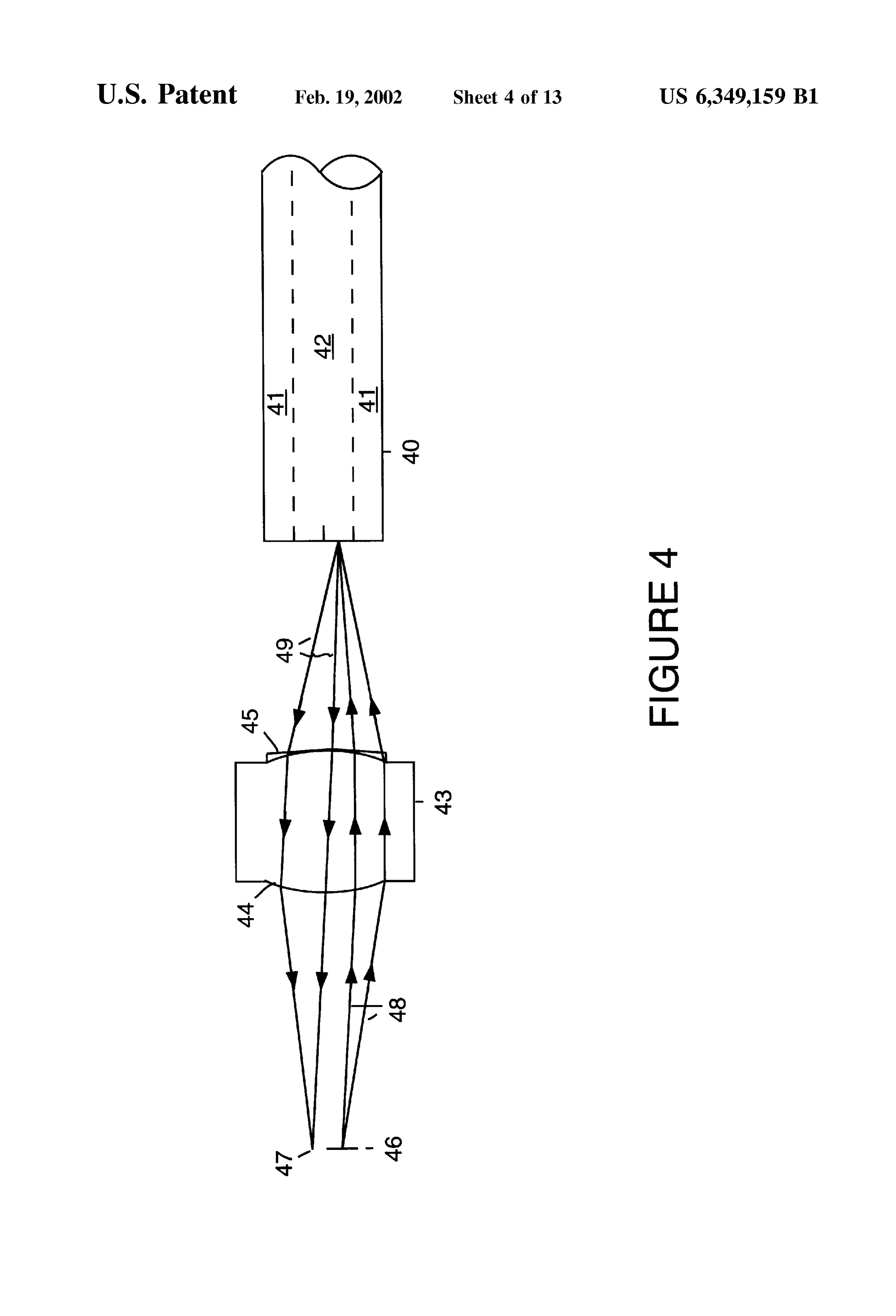
LENSES THAT LAUNCH HIGH BANDWIDTH FIG. 4 is a simplified block diagram of a fiber optic MODES INTO A FIBER OPTIC CABLE coupling lens used to couple light generated by a VCSEL WHILE ELMINATING FEEDBACK TO A into an optical fiber in accordance with an alternative LASER preferred embodiment of the present invention.
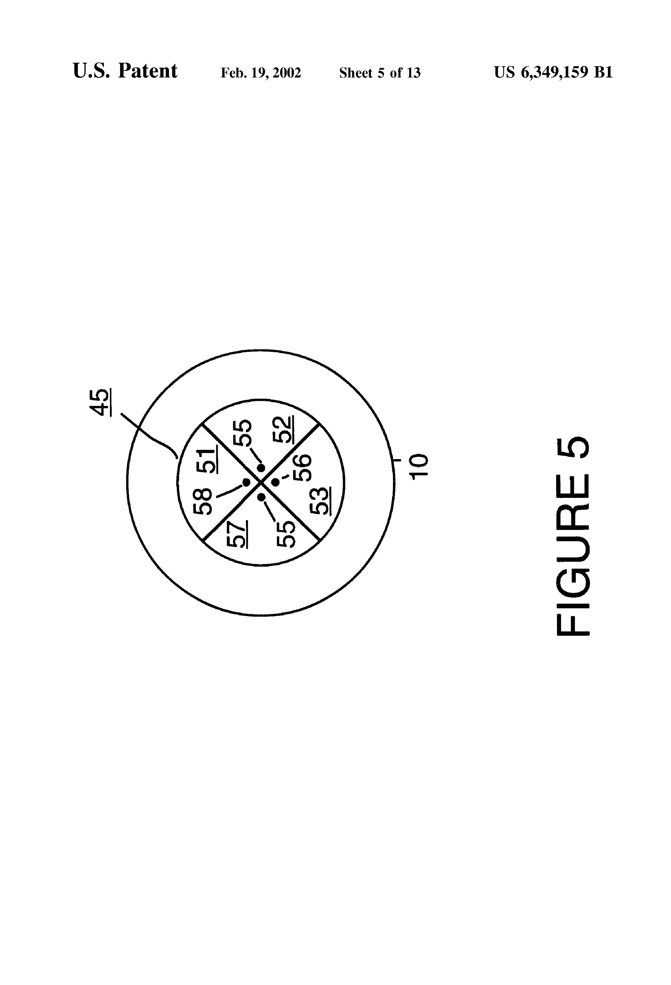
BACKGROUND FIG. 5 is a simplified end view of a four Zone lens surface of the fiber optic coupling lens shown in FIG. 4 in accor
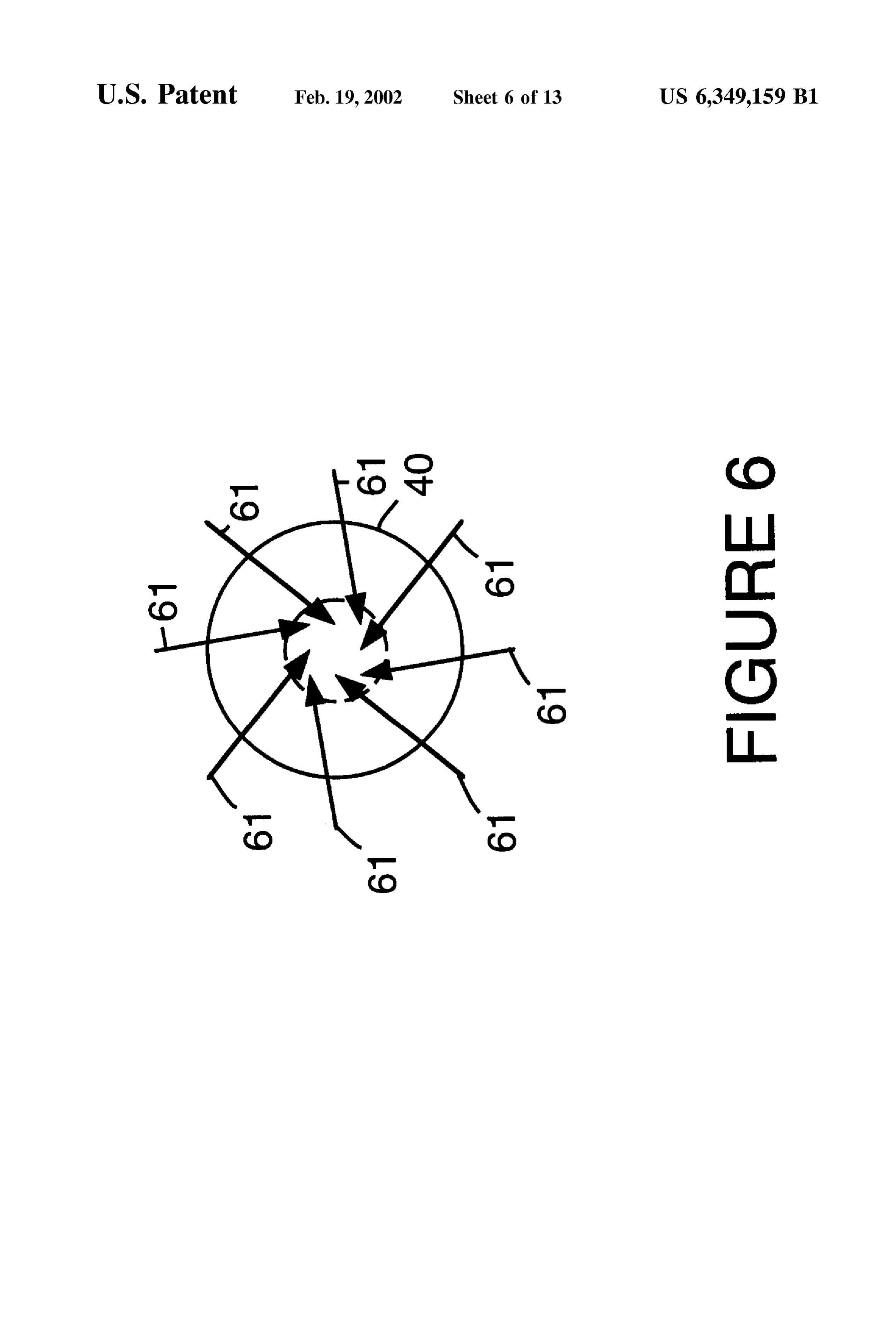
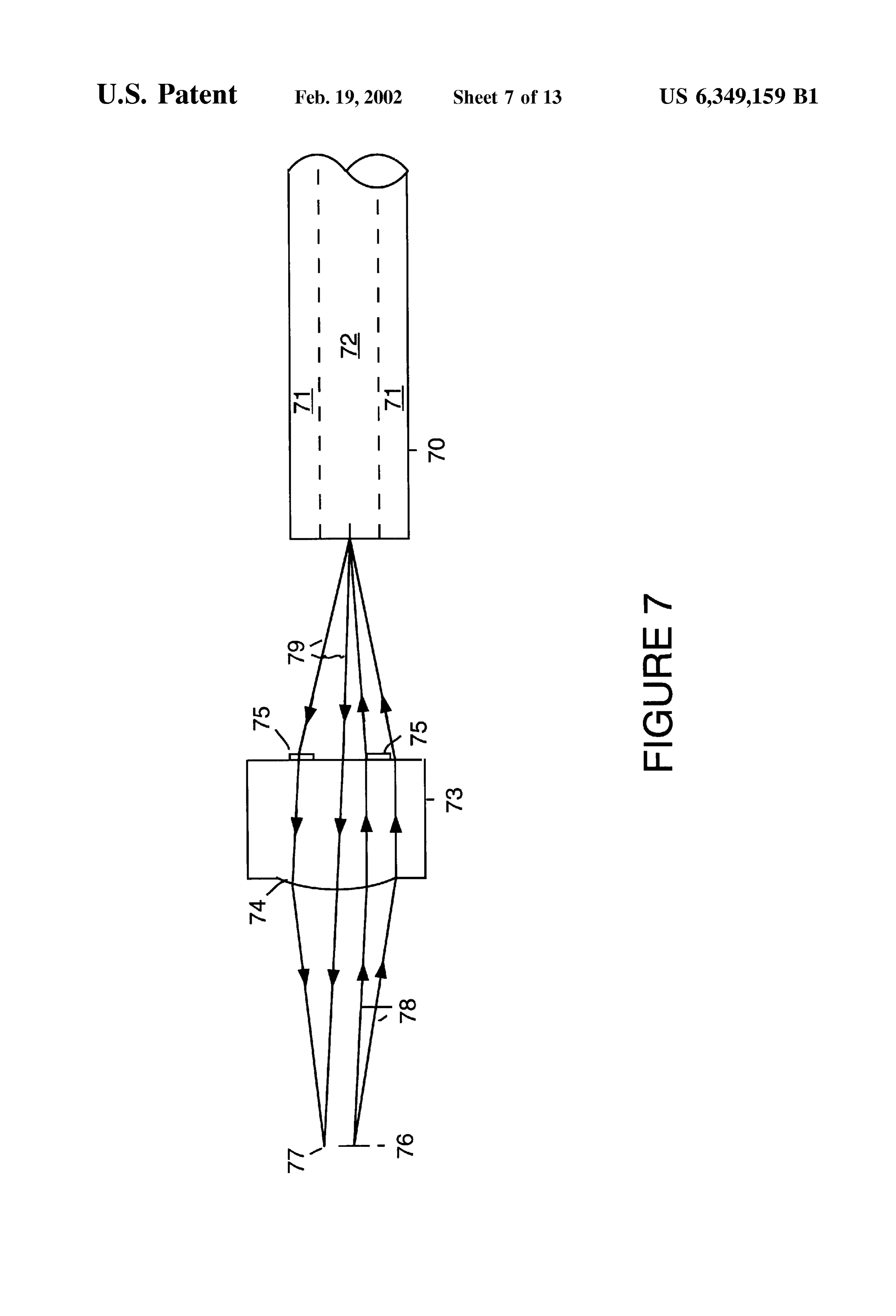
The present invention concerns laser technology and dance with a preferred embodiment of the present invention. pertains particularly to lenses that launch high bandwidth FIG. 6 is a simplified diagram illustrating ray paths on an modes into a fiber optic cable while reducing or eliminating end of the optical fiber shown in FIG. 4 in accordance with feedback to a laser. A vertical cavity Surface emitting laser 1O a preferred embodiment of the present invention. (VCSEL) emits light in a beam vertically from its surface. FIG. 7 is a simplified block diagram of a fiber optic Light emitted from an VCSEL is typically focused by a coupling lens used to couple light generated by a VCSEL hyperbolic transfer lens (HTL) into an optical fiber and used into an optical fiber in accordance with an alternative for transmission of data. Transmission technology Such as preferred embodiment of the present invention. Gigabit Ethernet technology utilizes VCSELS and multi 15 FIG. 8 is a simplified end view of a spiral Fresnel surface mode fiber optic cabling. of the fiber optic coupling lens shown in FIG. 7 in accor In order to achieve maximum link length, it is desirable dance with a preferred embodiment of the present invention. that the different fiber modes excited by the laser propagate through a fiber optic cable at the same Speed. This allows the onFIG. an 9 is a simplified diagram illustrating skew ray paths end of the optical fiber shown in FIG. 7 in accordance light to Simultaneously arrive at a destination. However, with a preferred embodiment of the present invention. there are many installed fiber optic cables with various indeX FIG. 10 is a simplified block diagram of a fiber optic anomalies that can cause certain bandwidth modes to propa coupling lens used to couple light generated by a VCSEL gate at Speeds different than desired.
into an optical fiber in accordance with an alternative
SUMMARY OF THE INVENTION 25 preferred embodiment of the present invention.
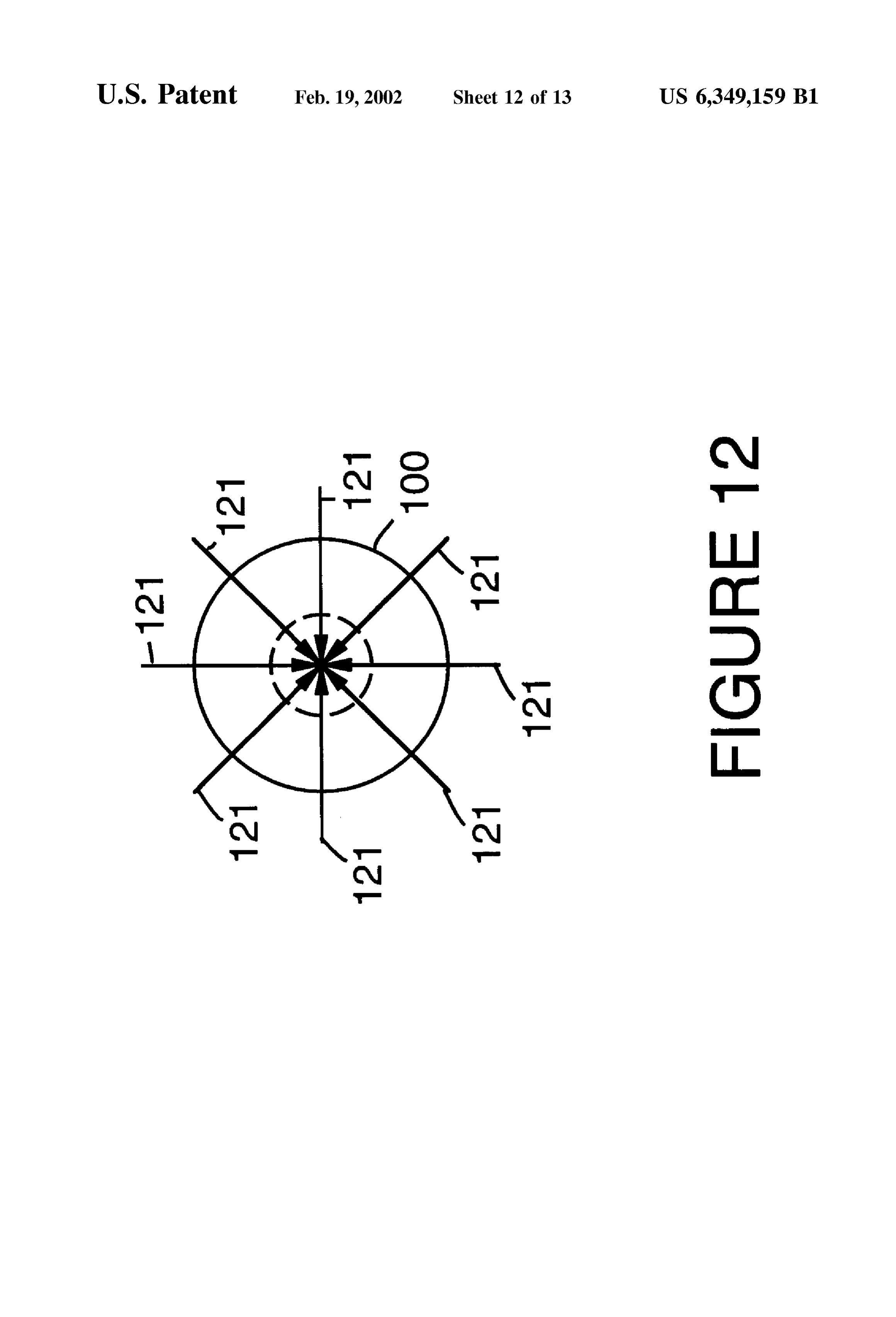
In accordance with the preferred embodiment of the FIG. 11 is a simplified end view of a spherical surface of present invention, a light transmission System includes a the fiber optic coupling lens shown in FIG. 10 in accordance laser, an optical fiber and a transfer lens. The transfer lens with a preferred embodiment of the present invention. transfers light emitted by the laser into the optical fiber. The FIG. 12 is a simplified diagram illustrating radial ray transfer lens includes a hyperbolic collimating Surface for paths on an end of the optical fiber shown in FIG. 10 in receiving and collimating light originating from the laser. accordance with a preferred embodiment of the present The transfer lens also includes an output lens Surface shaped invention.
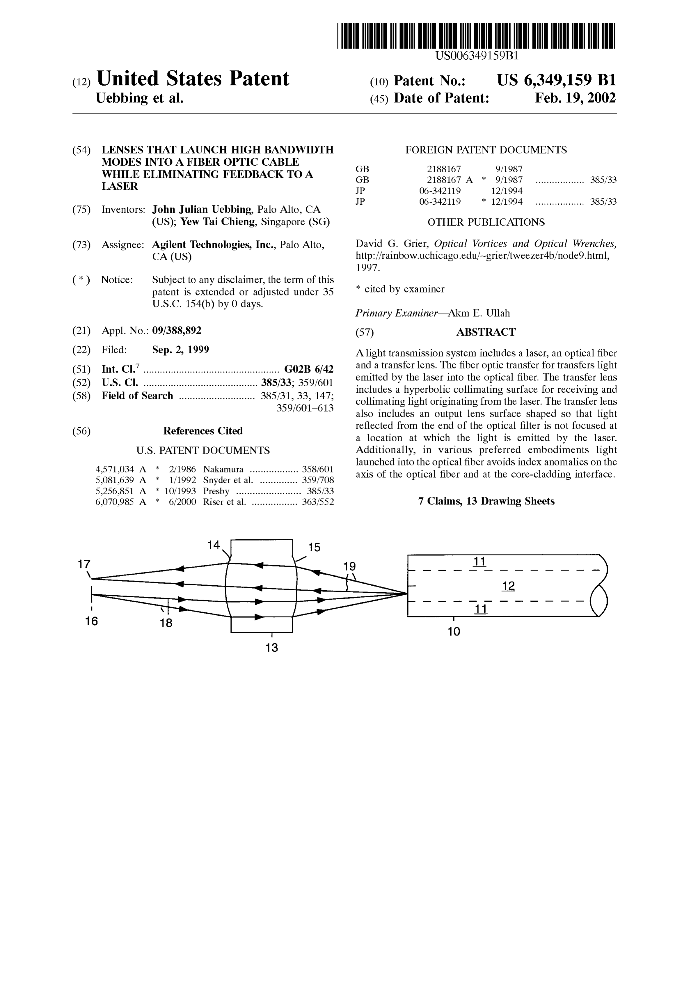
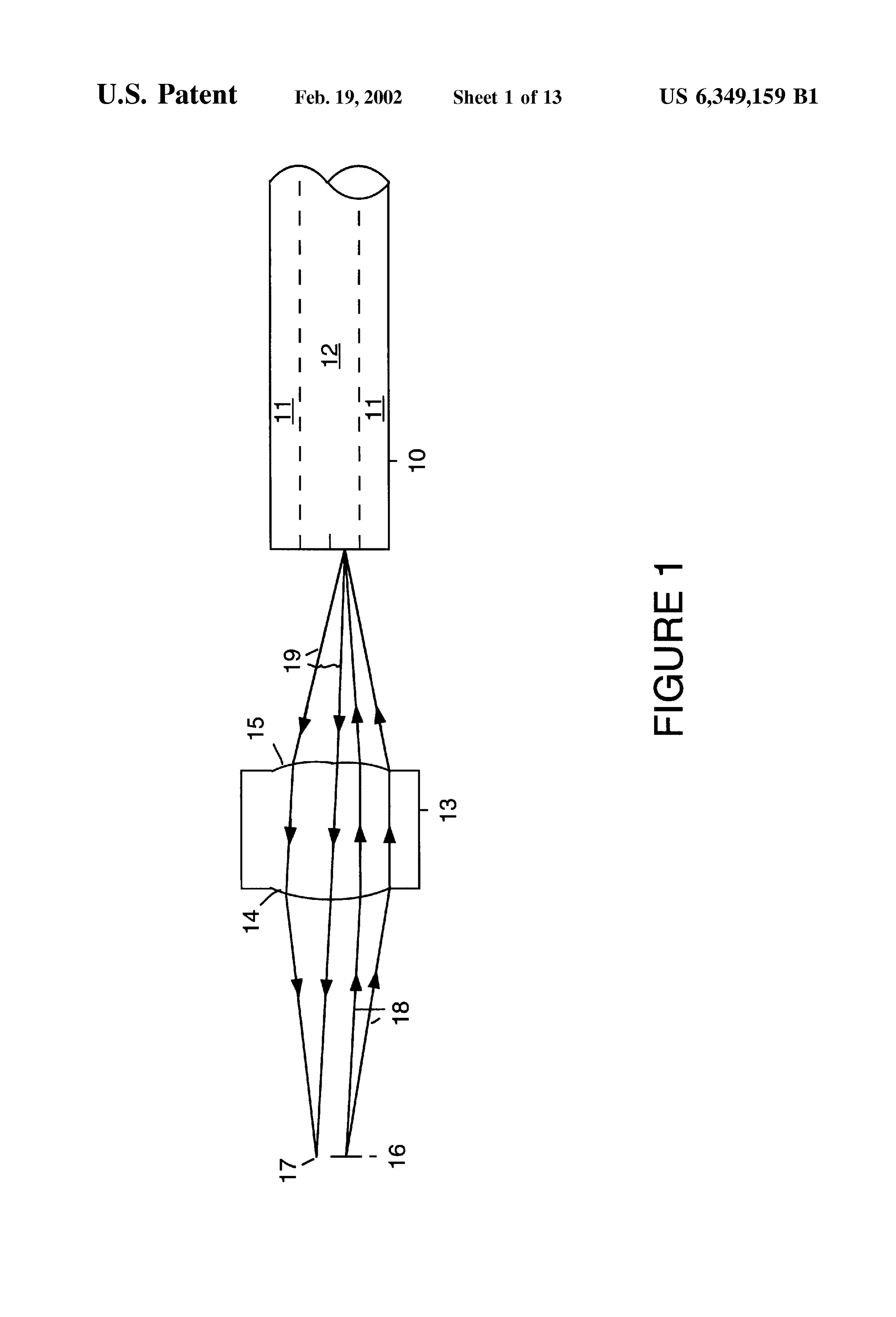
so that light reflected from the transfer lens is not focused at FIG. 13 is a simplified block diagram of a fiber optic a location at which the light is emitted by the laser. 35 coupling lens used to couple light generated by a VCSEL Additionally, in various preferred embodiments light into an optical fiber in accordance with an alternative launched into the optical fiber avoids indeX anomalies on the preferred embodiment of the present invention. axis of the optical fiber and indeX anomalies at the core DESCRIPTION OF THE PREFERRED cladding interface within the optical fiber. EMBODIMENT For example, the laser is a vertical cavity Surface emitting 40 laser. The output lens Surface can be, for example, a toroidal FIG. 1 is a simplified block diagram of a transfer lens 13 lens Surface, a multiple Zone lens Surface, a spiral Fresnel used to couple light generated by an emitting Surface 16 of lens Surface or a spherical lens Surface. a vertical cavity Surface emitting laser (VCSEL) into an In these light transmission Systems, optical feedback to optical fiber 10. FIG. 1 is meant to be illustrative and is not the laser is reduced. The various embodiments of the present 45 drawn to Scale in the vertical direction. Transfer lens 13 has invention can insure a low coupled power reflected from the a hyperbolic collimating lens Surface 14 and a toroidal lens end of the optical fiber to the laser sufficient to insure surface 15. Optical fiber 10 has a core region 12 and a Satisfactory operation. The low two pass transmissivity back cladding region 11. Transfer lens 13 is composed of, for to the laser of the output lens Surface can decrease the example, Ultem plastic.
feedback power by as much as 25 dB. If too much power is 50 Light rays 18 represent light rays generated by emitting coupled back into the laser from the reflection from the end Surface 16 of the VCSEL which are collimated and launched of the optical fiber, instabilities occur in the laser and the into optical fiber 10 by transfer lens 13. Light rays 19 output power oscillates up and down, causing extra and represent light rays reflected from the Surface of optical fiber damaging amounts of jitter as the received Signal pulses. 10. Only rays launched into one side of the lens are shown BRIEF DESCRIPTION OF THE DRAWINGS 55 for clarity. Rays are actually launched all over the input lens Surface.
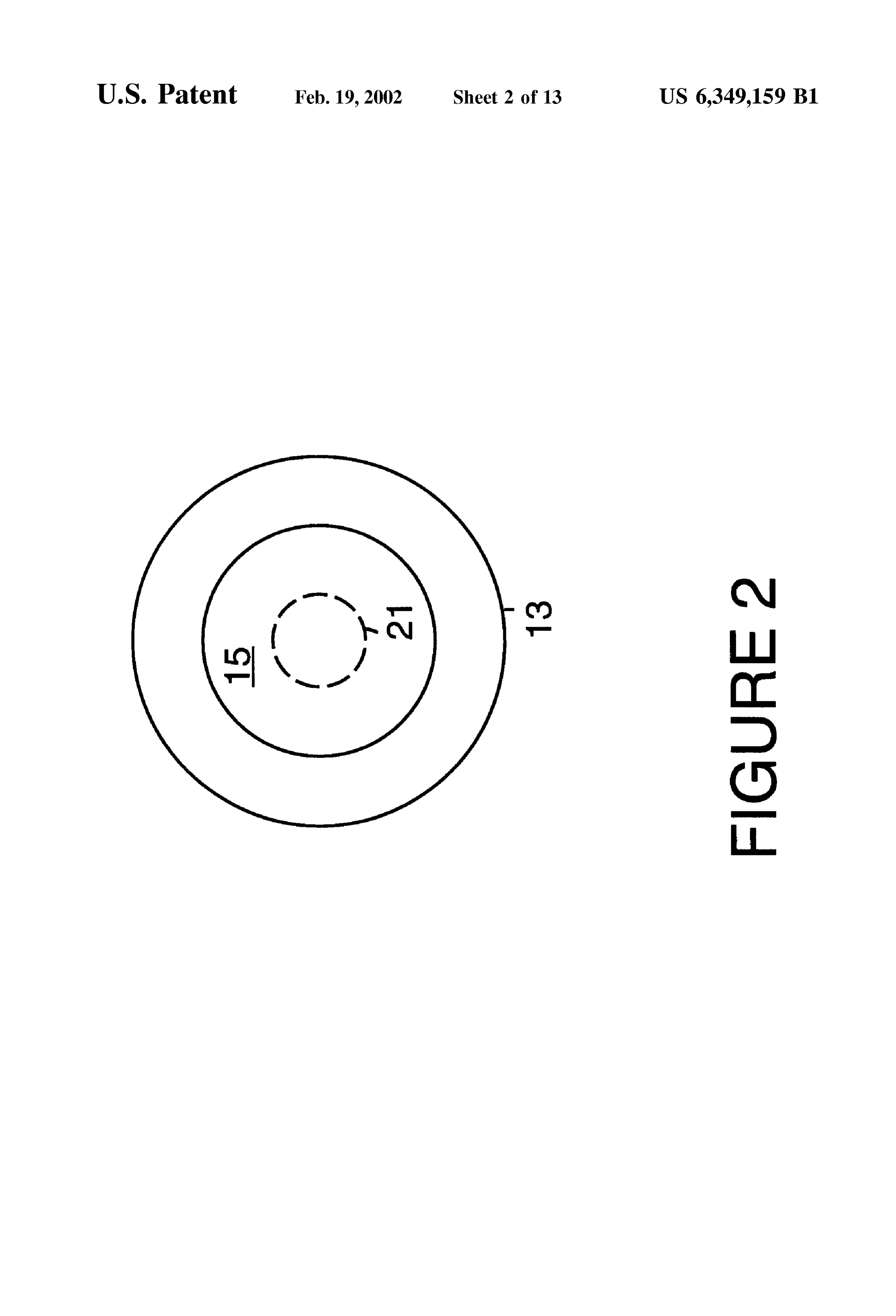
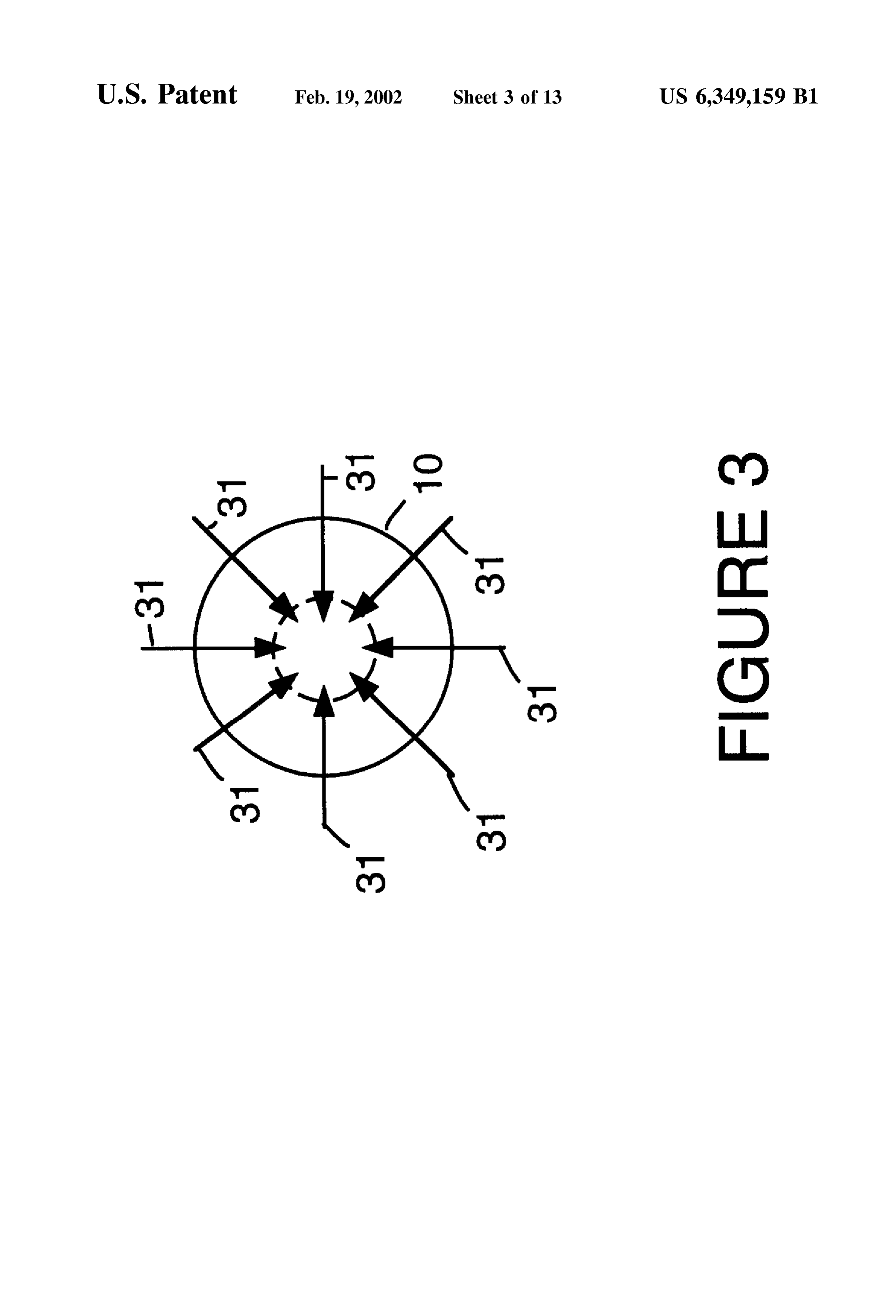
FIG. 1 is a simplified block diagram of a fiber optic Transfer lens 13 is shaped to maximize the amount of coupling lens used to couple light generated by a vertical light generated by emitting surface of the VCSEL which is cavity surface emitting laser (VCSEL) into an optical fiber received into optic fiber 10 by being focused by transfer lens in accordance with a preferred embodiment of the present 60 13. Further, transfer lens 13 is shaped to overcome the invention. existence of various indeX anomalies within installed optical FIG. 2 is a simplified end view of a toroidal lens surface fibers. The various indeX anomalies can cause certain modes of the fiber optic coupling lens shown in FIG. 1 in accor to propagate at Speeds different than desired. dance with a preferred embodiment of the present invention. The use of toroidal lens surface 15 gives a conditioned FIG. 3 is a simplified diagram illustrating radial ray paths 65 launch to maximize the modal bandwidth and effective link on an end of the optical fiber shown in FIG. 1 in accordance length. The use of toroidal lens surface 15 overcomes a with a preferred embodiment of the present invention. problem with hyperbolic transfer lenses. Particularly, hyper
Page 16
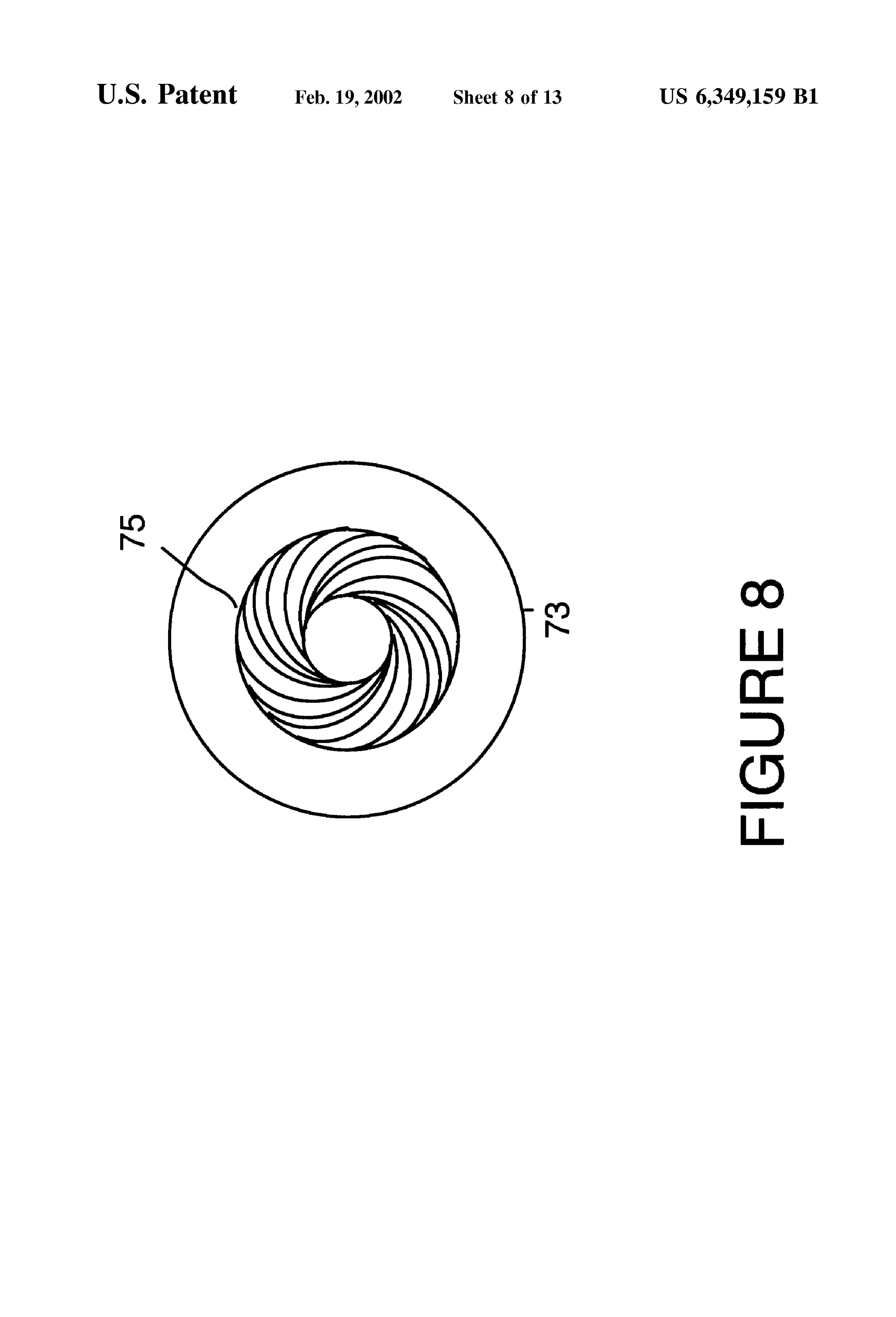
bolic transfer lenses can give Such good focusing that when a VCSEL into an optical fiber 70. FIG. 7 is meant to be focused, a small fraction of the light generated by VCSEL illustrative and is not drawn to Scale in the vertical direction. can return back directly back the light Source origin. The use Transfer lens 73 has a hyperbolic collimating lens surface 74 of toroidal lens surface 15 drastically reduces optical feed and a spiral Fresnel lens surface 75. Spiral Fresnel lens back. surface 75 has a spiral grooved shape. Optical fiber 70 has Toroidal lens Surface 15 focuses a point Source into a ring. isa core region 72 and a cladding region 71. Transfer lens 73 composed of, for example, Ultem plastic.
For example, toroidal lens surface 15 takes the light colli Light rayS 78 represent light rays generated by emitting mated by hyperbolic collimating lens Surface 14 and focuses the light into a 25 micrometer diameter ring on the end of surface 76 of the VCSEL which are launched into optical optical fiber 10. Because reflected light 19 passes through fiber 70 by transfer lens 73. Light rays 79 represent light rays the opposite Side of the lens, the reflected light comes back reflected from the surface of optical fiber 70 to locations into a ring of twice the diameter of the ring on optical fiber represented by a location 77. Only one side of the light rays 10 plus any correction for magnification. For example, with are shown for clarity.
a 1.5:1 magnification on transfer lens 13, the actual diameter light Transfer lens 73 is also shaped to maximize the amount of of reflected light at emitting surface 16 of the VCSEL is 33 received
generated by emitting surface of the VCSEL which is micrometers. The energy returns at a ring (represented in fer lens into optical fiber 70 and propagated through trans FIG. 1 by a location 17) removed from the emitting surface overcome the Further, 73. transfer lens 73 also is shaped to existence of various indeX anomalies within 16 of the VCSEL, so the mode overlap integral will be small. installed optical fibers. The various indeX anomalies can FIG. 2 is a simplified end view of transfer lens 13 and cause certain modes to propagate at Speeds different than toroidal lens surface 15. Toroidal lens surface 15 shows high desired.
points 21 In one preferred embodiment the depth of the outer FIG. 3 is a simplified diagram illustrating radial ray paths groove of the spiral Fresnel lens surface 75 is 28 microme 31 on an end of optical fiber 10. ters. The tolerance on reactive ion etching the mold insert is FIG. 4 is a simplified block diagram of a transfer lens 43 25 about 2.5%, so the groove depth variation would be 0.7 used to couple light generated by an emitting Surface 46 of micrometer. With an Ultem index of 1.632, this corresponds a VCSEL into an optical fiber 40. FIG. 4 is meant to be to a phase error of 0.4 micrometers. This is a large fraction illustrative and is not drawn to Scale in the vertical direction. of the 0.85 micrometer operating wavelength. To keep the Transfer lens 43 has a hyperbolic collimating lens surface 44 error down to 0.1 times the wavelength (0) the groove depth and a four Zone lens surface 45. Optical fiber 40 has a core is 5 micrometer. This corresponds to a depth of 42. One way region 42 and a cladding region 41. Transfer lens 43 is of doing this is to Split each groove into Several Small ones, composed of, for example, Ultem plastic. keeping a maximum phase depth of 4). Alternatively, a new Light rays 48 represent light rays generated by emitting shallow groove can be spawned off from the main groove as surface 46 of the VCSEL which are focussed and launched the phase depth reaches 4).
into optical fiber 40 by transfer lens 43. Light rays 49 35 FIG. 8 is a simplified end view of transfer lens 73 and represent light rays reflected from the Surface of optical fiber spiral Fresnel lens surface 75.
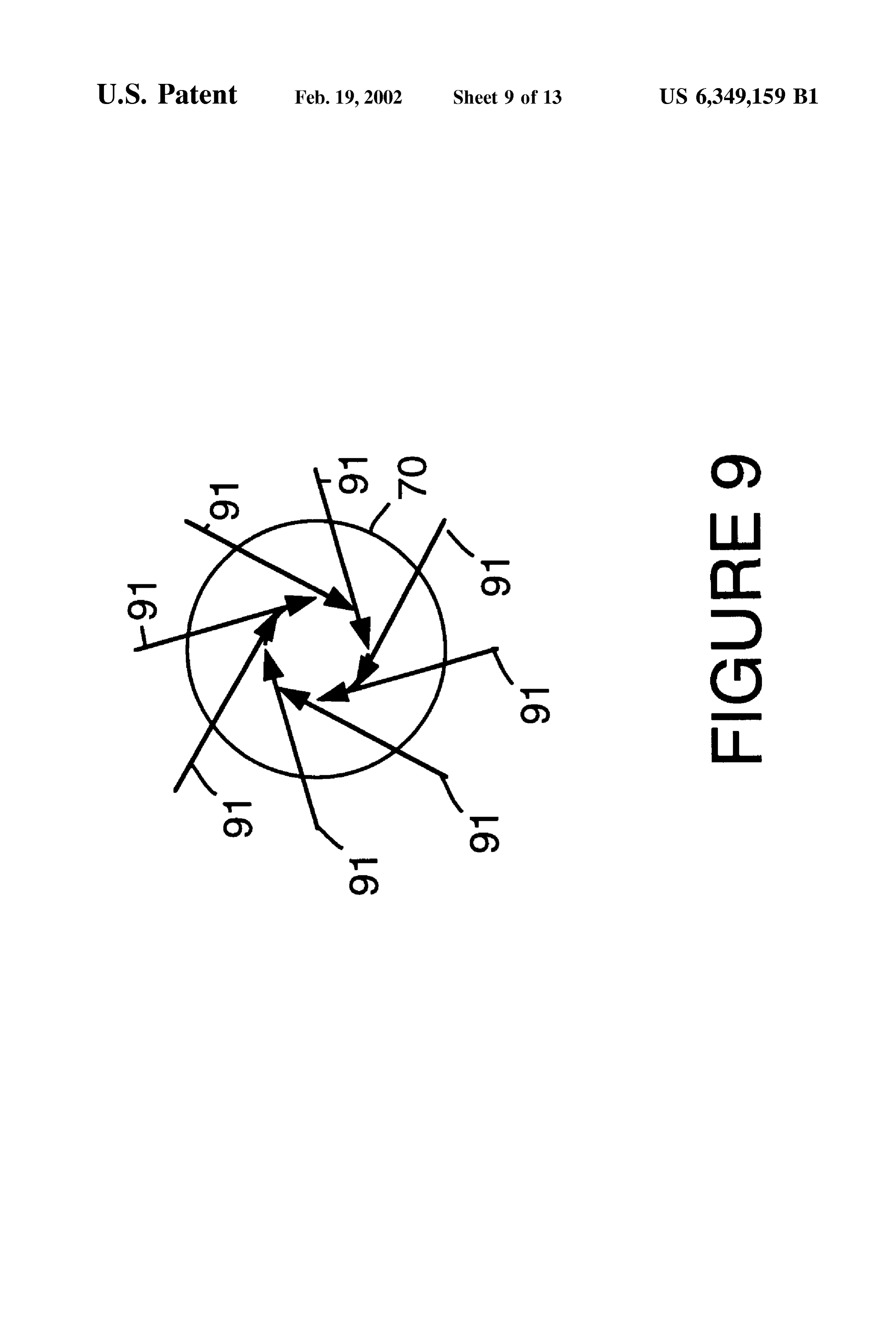
40 to locations represented by a location 47. For clarity, only FIG. 9 is a simplified diagram illustrating skew ray paths rays launched into one Side of the lens are shown. 91 on an end of optical fiber 70 from a point source laser. As Transfer lens 43 is also shaped to maximize the amount of can be seen from FIG. 9, spiral Fresnel lens surface 75 light generated by the emitting surface of the VCSEL which 40 launches into optical fiber 70 skew rays, at a tangent and off is received into optical fiber 40. Further, transfer lens 43 also axis. Skew rays, at a tangent and off axis are very advan is shaped to overcome the existence of various indeX anoma tageous when launching high modal bandwidth Signals in lies within installed optical fibers. The various index anoma optical fibers with indeX anomalies at the center and edge. lies can cause certain modes to propagate at Speeds different Such rays never See the center or edge of the optical fiber. than desired. FIG. 10 is a simplified block diagram of a transfer lens
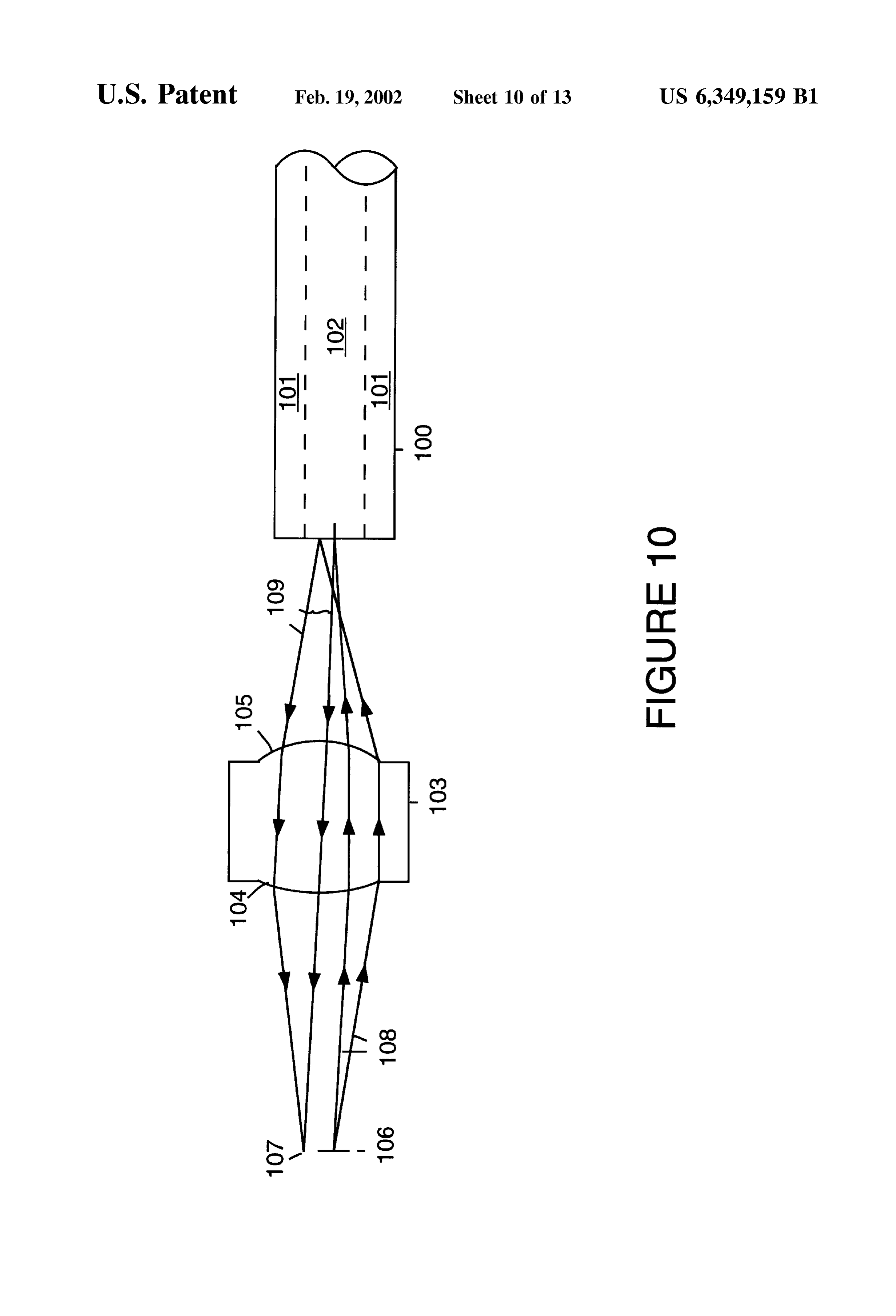
The use of four Zone lens surface 45 takes advantage of 103 used to couple light generated by an emitting Surface the four lobes in the VCSEL radiation pattern. For example, 106 of a VCSEL into an optical fiber 100. FIG. 10 is meant light from each of lobes in the VCSEL radiation pattern is to be illustrative and is not drawn to Scale in the vertical focused onto the end of optical fiber 40 approximately direction. Transfer lens 103 has a hyperbolic collimating tangent to a 25 micrometer diameter focal ring. Four Zone 50 lens surface 104 and a spherical lens surface 105. Optical lens Surface 45 has four Segments, each with their focal fiber 100 has a core region 102 and a cladding region 101. points (optical axis) at the approximate tangent point. Transfer lens 103 is composed of, for example, Ultem For example, transfer lens 43 produces a VCSEL image plastic.
that is 21 micrometer Square. Light will be kept away from Light rays 108 represent light rays generated by emitting the center of optical fiber 40 and so the modal bandwidth 55 Surface 106 of the VCSEL which are collimated and will increase. launched into optical fiber 100 by transfer lens 103. Light FIG. 5 is a simplified end view of transfer lens 43 and four rays 109 represent light rays reflected from the surface of Zone lens Surface 45. Four Zone lens Surface 45 has a Zone optical fiber 100 to locations represented by a location 107. 51, a Zone 52, a Zone 53 and a Zone 54. The optical axis for Transfer lens 103 is also shaped to maximize the amount Zone 51 is a point 55 within Zone 52. The optical axis for 60 of light generated by emitting Surface of the VCSEL which Zone 52 is a point 56 within Zone 53. The optical axis for is received into optical fiber 100 and propagated through Zone 53 is a point 57 within Zone 54. The optical axis for transfer lens 103.
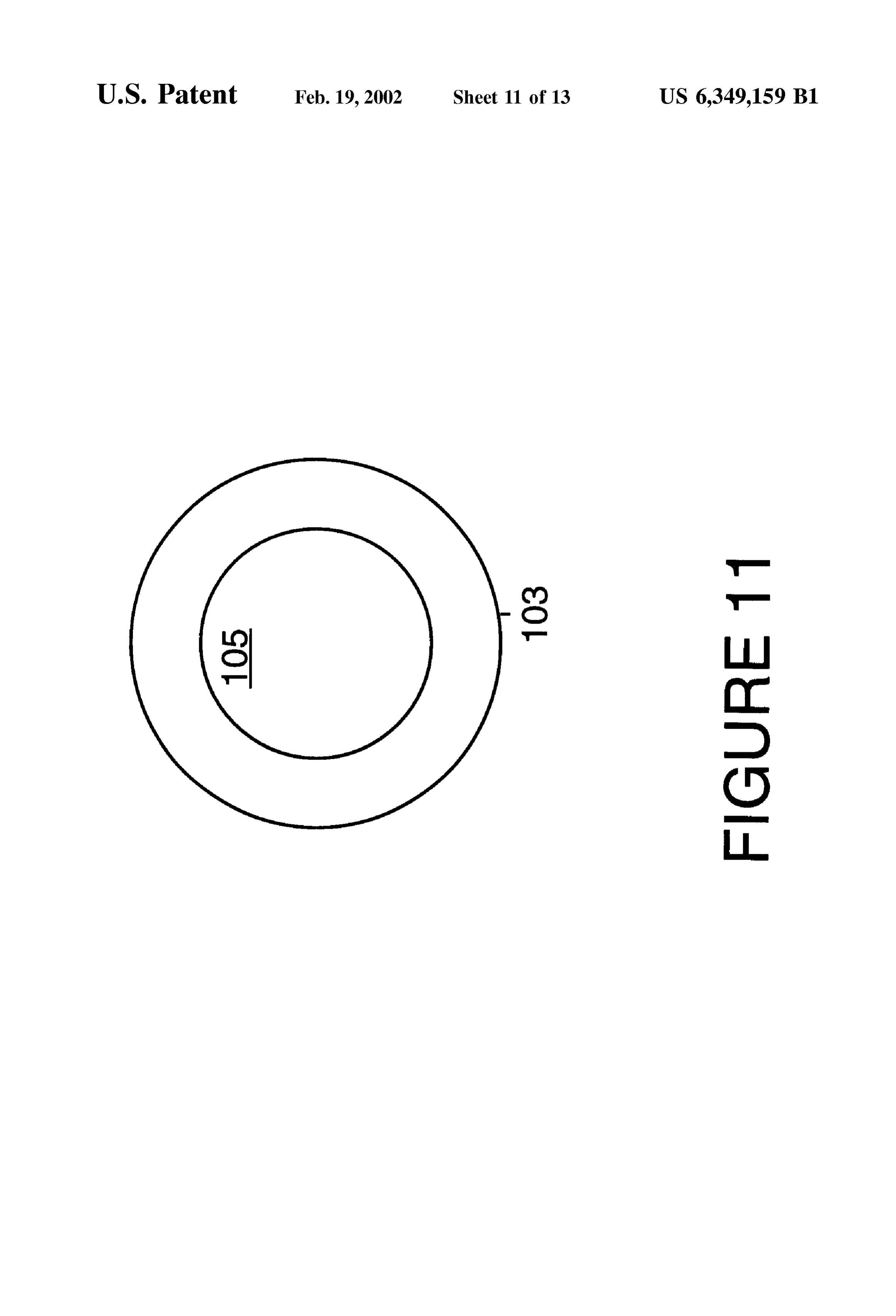
Zone 54 is a point 58 within Zone 51. FIG. 11 is a simplified end view of transfer lens 103 and FIG. 6 is a simplified diagram illustrating radial ray paths spherical lens surface 105.
61 on an end of optical fiber 40 from a point source laser. 65 FIG. 12 is a simplified diagram illustrating radial ray FIG. 7 is a simplified block diagram of a transfer lens 73 paths 121 on an end of optical fiber 100 from a point source used to couple light generated by an emitting Surface 76 of laser.
Page 17
S 6
In FIG. 10, the location of the hyperbolic collimating lens We claim:
Surface can be exchanged with the location of the Spherical 1. A light transmission System comprising: lens Surface. The resulting illumination gives Superior cou pling to the optical fiber and reduced coupling back to the a laser,
VCSEL. an optical fiber; and,
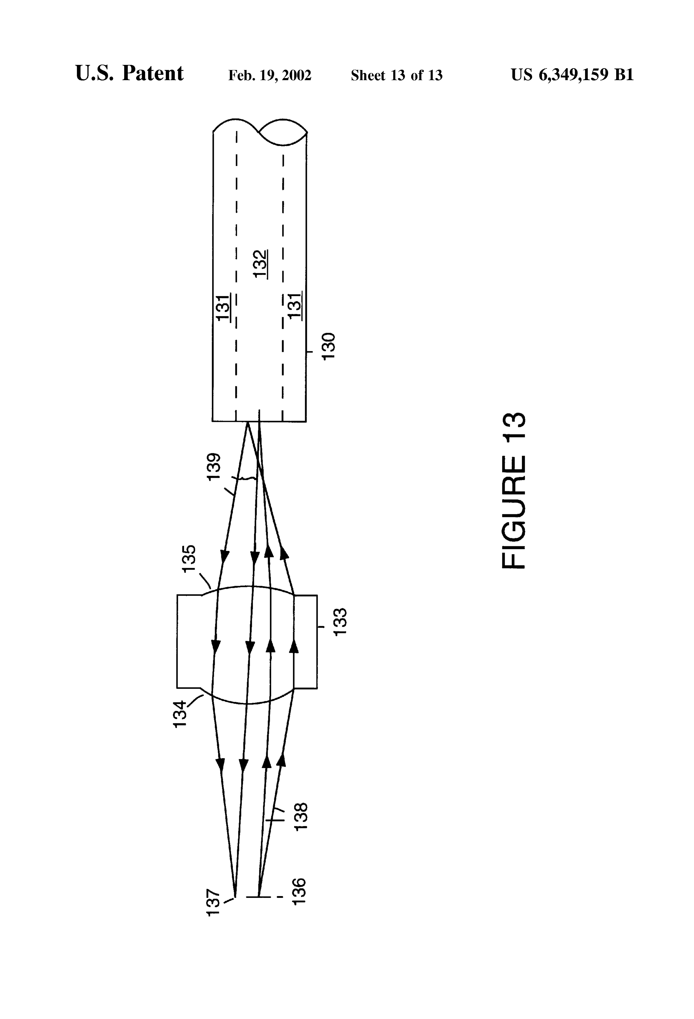
For example, FIG. 13 is a simplified block diagram of a a transfer lens for transferring light emitted by the laser transfer lens 133 used to couple light generated by an into the optical fiber, the transfer lens including: emitting surface 136 of a VCSEL into an optical fiber 130. a hyperbolic collimating Surface for receiving and FIG. 13 is meant to be illustrative and is not drawn to Scale collimating light originating from the laser, and in the vertical direction. Transfer lens 133 has a spherical an output lens Surface shaped So that: lens surface 134 and a hyperbolic lens surface 135. Optical light reflected from the optical fiber back through the fiber 130 has a core region 132 and a cladding region 131. transfer lens is not focused at a location at which Transfer lens 133 is composed of, for example, Ultem the light is emitted by the laser, and plastic. light launched into the optical fiber is not focused on Light rays 138 represent light rays generated by emitting 15 a center axis of the optical fiber. surface 136 of the VCSEL which are launched into optical 2. A light transmission System as in claim 1 wherein the fiber 130 by transfer lens 133. Light rays 139 represent light laser is a vertical cavity Surface emitting laser. rays reflected from the surface of optical fiber 130 to 3. A light transmission System as in claim 1 wherein the locations represented by a location 137. output lens Surface is also shaped So that light launched into Transfer lens 133 is also shaped to maximize the amount the optical fiber avoids indeX anomalies on a cladding of light generated by emitting Surface of the VCSEL which interface within the optical fiber.
is received into optical fiber 130 and propagated through 4. A light transmission System as in claim 1 wherein the transfer lens 133. output lens Surface is a toroidal lens Surface. The foregoing discussion discloses and describes merely 25 5. A light transmission System as in claim 1 wherein the exemplary methods and embodiments of the present inven output lens Surface is a multiple Zone lens Surface. tion. As will be understood by those familiar with the art, the 6. A light transmission System as in claim 1 wherein the invention may be embodied in other specific forms without output lens Surface is a four Zone lens Surface. departing from the Spirit or essential characteristics thereof. 7. A light transmission System as in claim 1 wherein the Accordingly, the disclosure of the present invention is output lens Surface is a spiral Fresnel lens Surface. intended to be illustrative, but not limiting, of the Scope of the invention, which is set forth in the following claims. k k k k k
Provenance
- Collection
- Cited prior art
- Original PDF
- patentimages.storage.googleapis.com →
- Filed
- 1999-09-02
- Pages
- 17
- Method
- pdftotext (the PDF's own text layer) + pdftoppm 300dpi page scans
- Source
- Google Patents bibliographic record
- Granted
- 2002-02-19
- Inventors
- John Julian Uebbing; Yew Tai Chieng; Agilent Technologies Inc
- Transcribed from
- patentimages.storage.googleapis.com →