patent · US4112889
Fuel system and vaporizer for internal combustion engines
12 September 1978
Page 1 — bibliographic record
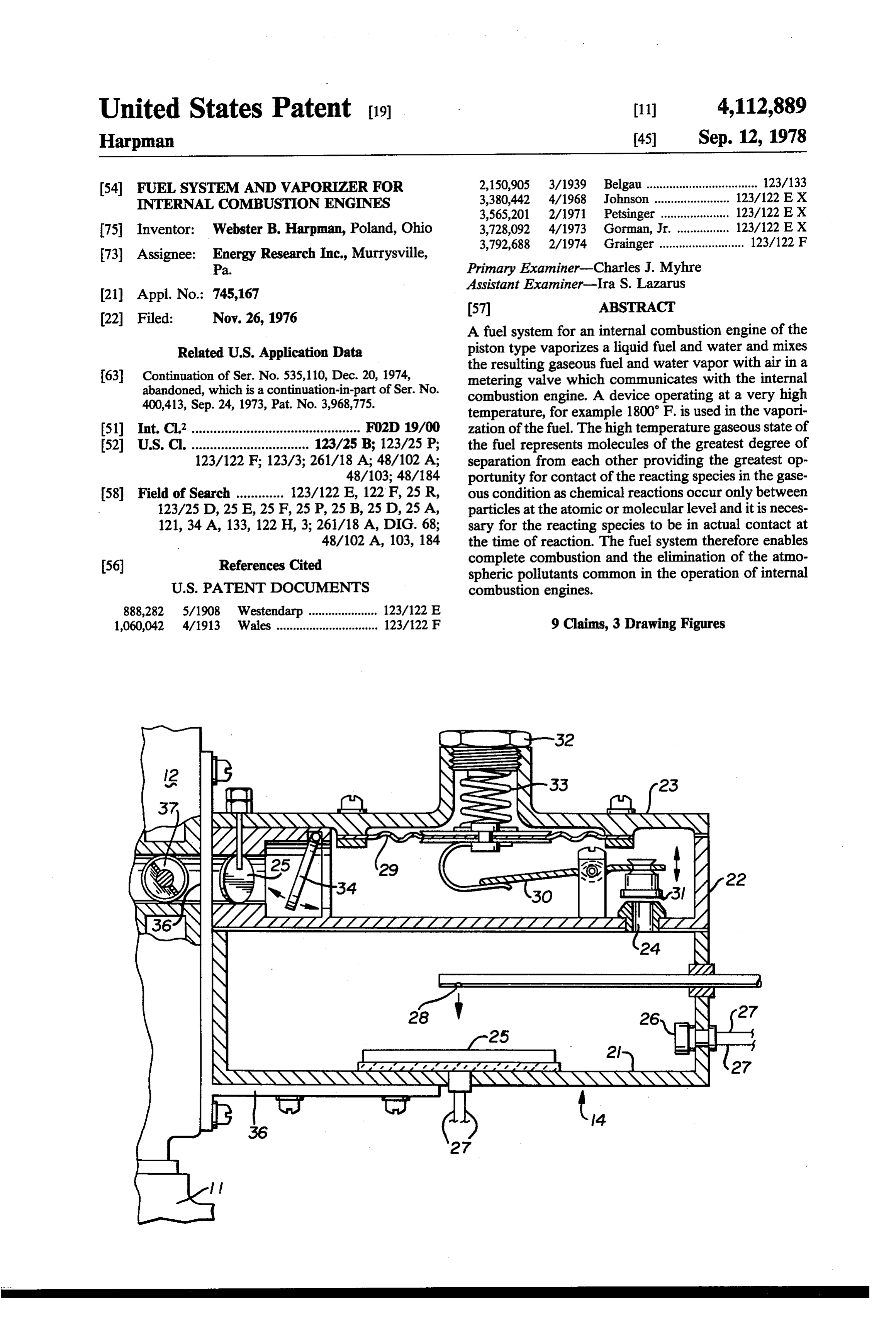
United States Patent (19) 11 4,112,889 Harpman 45) Sep. 12, 1978 54 FUEL SYSTEMAND WAPORIZER FOR 2,150,905 3/1939 Belgau .................................. 123/133 INTERNAL COMBUSTION ENGINES 3,380,442 4/1968 Johnson ....... ... 123/122 E X 3,565,201 2/1971 Petsinger ..... ... 123/122 E X 75 Inventor: Webster B. Harpman, Poland, Ohio 3,728,092 4/1973 Gorman, Jr. ................ 123/122 E X 73 Assignee: Energy Research Inc., Murrysville, 3,792,688 2/1974 Grainger .......................... 123/122 F Pa. Primary Examiner-Charles J. Myhre 21 Appl. No.: 745,167 Assistant Examiner-Ira S. Lazarus (22 Filed: Nov. 26, 1976 57 ABSTRACT A fuel system for an internal combustion engine of the
Related U.S. Application Data R RE vaporizesf s fuel and water s mixes - the resulting gaseous fuel and water vapor with air in a
metering valve which communicates with the internal combustion engine. A device operating at a very high yr ws y w if avy is esw8 a wss sye temperature, for example 1800 F. is used in the vapori 51) Int. Cl’.............................................. FO2D 19/00 zation of the fuel. The high temperature gaseous state of 52 U.S. C. ................................ 123/25B; 123/25 P; the fuel represents molecules of the greatest degree of 123/122 F; 123/3; 261/18 A; 48/102 A; separation from each other providing the greatest op 48/103; 48/184 portunity for contact of the reacting species in the gase 58 Field of Search ............. 123/122 E, 122 F, 25R, ous condition as chemical reactions occur only between 123/25 D, 25 E, 25 F, 25 P, 25 B, 25 D, 25A, particles at the atomic or molecular level and it is neces 121, 34A, 133, 122 H, 3; 261/18 A, DIG. 68; sary for the reacting species to be in actual contact at 48/102 A, 103, 184 the time of reaction. The fuel system therefore enables 56 References Cited complete combustion and the elimination of the atmo spheric pollutants common in the operation of internal
888,282 5/1908 Westendarp ..... - - - - - - - - A - 123/122 E 1,060,042 4/1913 Wales ............................... 123/122 F 9 Claims, 3 Drawing Figures
NYN
SISYN
NSSN N
NNN
Page 2
Drawing sheet — no readable text.
Page 3
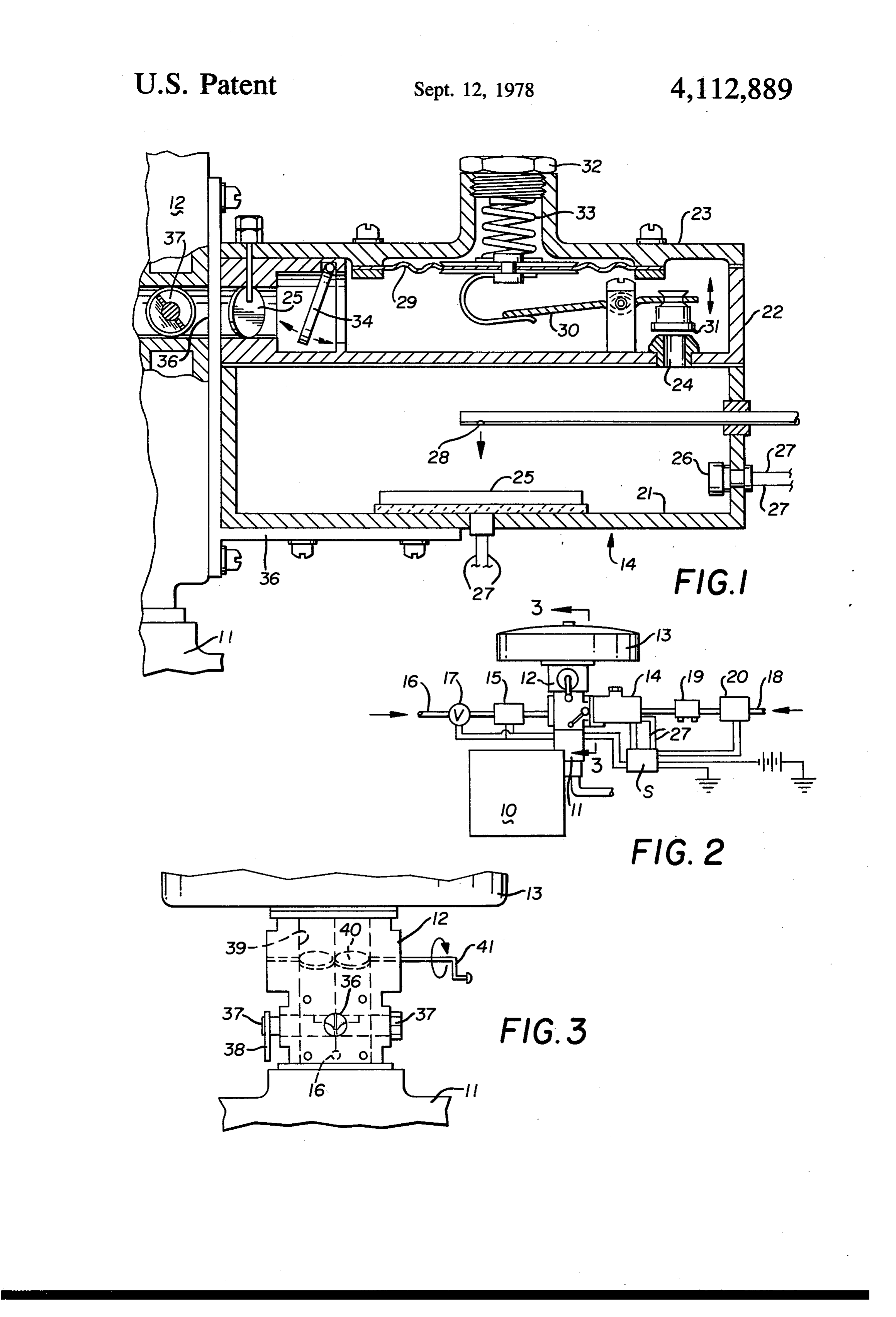
in communication with a metering valve 12 to which
FUEL SYSTEMAND WAPORIZERFORINTERNAL primary air is available as from an air cleaner 13. Vapor COMBUSTION ENGINES ized fuel in a gaseous form is delivered to the metering This is a continuation of application Ser. No. 535,110, valve 12 from a vaporizer 14 and water vapor is sup filed Dec. 20, 1974, now abandoned, which is a continu plied to the metering valve 12 by a boiler 15, by way of ation in part of application Ser. No. 400,413, filed Sept. a tubular conduit 16 having a solenoid valve 17 therein. 24, 1973, now U.S. Pat. No. 3,968,775. Liquid fuel such as gasoline is supplied the vaporizer
BACKGROUND OF THE INVENTION
14 by a fuel line 18 having a preheater device 19 therein and communicating with a pump 20.
1. Field of the Invention 10 By referring now to FIG. 1 of the drawings, it will be This invention relates to fuel systems and varporizing seen that the vaporizer 14 consists of a hollow body 21 devices therein for internal combustion engines of the having a closure formed of a secondary hollow body 22 piston type. which in turn is closed by a cap 23. A port 24 in the 2. Description of the Prior Art secondary hollow body 22 communicates with the hol Fuel systems for internal combustion engines of the 15 low body 21 and a vaporizing chamber therein. piston type have generally comprised carburetors in The hollow body 21 which forms the vaporizing which liquid fuel is delivered into a stream of air and chamber has a flat unbroken heater 25 which includes divided into a series offine droplets approaching vapor an electric heating element controlled by a temperature ization and immediately conveyed to the point of com and pressure actuated device 26 which acts to connect bustion. Only those molecules at the surface of the fuel 20 the electric heating element in the heater 25 with a droplets are in a position to react with another species power source by way of conductors 27. The arrange and incomplete combustion results because the very ment is such that the device 26 energizes the heater 25 short time allowed is insufficient for more than a little and the pump 20 and the electric heating element in the vaporization of the fuel to occur. The prior art engines heater 25 supplies sufficient heat to flash vaporize the therefore exhaust large quantities of hydrocarbons, 25 liquid fuel, at least 700' F. is necesary to produce a carbon monoxide and oxides of nitrogen all of which gaseous fuel.
are undesirable atmospheric pollutants. It has been determined that by operating the heater 25 This invention vaporizes the liquid fuel at very high at or near 1800 F. and directing the liquid fuel there temperatures so that in its heated gaseous state it will against by a nozzle 28 will provide a very rapid rate of detonate at a very high rate and adds the water vapor to 30 flash vaproziation and a desirable hot gaseous fuel. Still reduce the high rate of detonation of the fuel to achieve referring to FIG. 1 of the drawings, it will be seen that practically complete combustion and desirable reaction the secondary hollow body 22 of the vaporizer 14 de time in the internal combustion engine. fines a secondary chamber in which a diaphragm 29 is
SUMMARY OF THE INVENTION
positioned for the operation of a lever 30 which moves 35 a valve 31 toward and away from the port 24 which
A fuel system having novel high temperature vapor communicates with the vaporization chamber in the izer for an internal combustion engine of the piston type hollow body 21. The diaphragm 29, lever 30 and valve is disclosed in which liquid fuel such as gasoline is va 31 form a pressure regulator that is adjustable as by an porized to produce a gaseous fuel which is delivered adjustment bolt 32 which biases a spring 23 engaging under pressure to a metering valve. Simultaneously the diaphragm 29 as will be understood by those skilled water is vaporized and water vapor is delivered to the in the art. The arrangement is such that hot gaseous fuel same metering valve and the primary combustion air is pressures of up to 20 P.S.I. in the vaporization chamber available to the metering valve. The partial vacuum in the hollow body 21 are reduced to 4 or 5 ounces P. S. resulting from the operation of the pistons in the inter I. in the secondary hollow body 22. The regulating nal combustion engine moves the combustion air with 45 action acts to maintain a uniform supply of hot gaseous the proper quantities of gaseous fuel and water vapor to fuel at a desired low pressure so that is volume and/or the points of combustion in the cylinders of the engine. rate of flow into the metering valve is satisfactory under the vaporization of the liquid fuel and the water is all operating conditions. The flow rate and volume of caused by high temperature heat from an external air and hot gaseous fuel through the metering valve 12 SOCe, 50 and into the intake manifold 11 of the engine 10 is con DESCRIPTION OF THE DRAWINGS trolled by the metering valve 12. Throttle control of the engine is therefore the same as with a liquid fuel carbu
FIG. 1 is a cross sectional elevation of a liquid fuel retor as manually controlled butterfly and rotary valves vaporizer, in the metering valve 12 directly control the air and FIG. 2 is a diagrammatic illustration of a fuel system 55 gaseous fuel.
for an internal combustion engine and incorporating the By referring again to FIG. 1 of the drawings, it will vaporizer of FIG. 1, and be seen that the secondary hollow body 22 incorporates FIG. 3 is an enlarged detail view of a portion of the a check valve 34 and a butterfly valve 35 respctively fuel system. downstream in the hot gaseous fuel flow path there DESCRIPTION OF THE PREFERRED from. The check valve 34 is open downstream, and the EMBODIMENT butterfly valve 33 enables the amount of hot gaseous fuel flowing from the vaporizer to be set.
By referring to the drawings and FIG. 2 thereof, the Those skilled in the art will observe that a desirable form of the invention chosen for illustration and de ratio between the gaseous fuel and the water vapor scription herein may be seen. A fuel system for an inter 65 delivered the metering valve 12 by the fuel system here nal combustion engine is illustrated in operative com inbefore described is desirable and it has been deter municaton with an internal combustion engine 10 of the mined that the water vapor obtained from 1 gallon of piston type in which the inlet manifold is indicated at 11 water uniformly and continuously supplied the meter
Page 4
ing valve 12 provides a suitable ratio with respect to 40 ucts which may be more toxic than the original fuel and gallons of liquid gasoline delivered to the vaporizer 14 the elimination of the possibility of such pyrolysis prod by the pump 20. ucts in the exhaust may be achieved by insuring as com It will further occur to those skilled in the art that an plete combustion as possible with the invention herein anti-freeze additive such as alcohol can be added to the 5 before described.
water supplied the boiler 15 without affecting the oper A series of tests with a V8 engine at several engine ation of the device and without changing the water speeds are noted on an attached page; a part of this vapor gaseous fuel ratio significantly. specification by reference.
The metering valve 12 may comprise any suitable The test results provide a comparison of the exhaust commercial device which will control the amount of air 10 emissions of the same engine, with gasoline, with and and a gaseous fuel admitted thereto for delivery to the without the fuel system of the invention, with propane inlet manifold 11 and one such suitable metering valve is (a gaseous fuel) and with and without the water vapor. generally available under the trademark CENTURY. Th test results show hydrocarbons in the exhaust in In the preferred embodiment as seen in FIGS. 2 and 3 parts per million and the percentages of carbon monox the metering valve 12 provides throttle control with 15 ide present.
respect to the amount of the air and hot gaseous fuel Those skilled in the art will recognize that oxides of admitted to the inlet manifold 11 of the internal combus nitrogen in exhaust emissions vary with the degree of tion engine, responsive to the partial vacuum in the inlet combustion of the fuel and it is therefore believed that manifold 11 as will be understood by those skilled in the the fuel system of this invention reduces such emissions art and the water vapor may be introduced into the 20 in the same or similar ratio as the reduction of hydrocar metering valve 12 and similarly metered thereby or the bons and carbon monoxide.
very small quantity of water vapor required may be continously injected therein when the fuel system is tion has beenbut
Although one embodiment of the present inven illustrated and described, it will be appar operating.
The metering valve 12 hereinbefore referred to is 25 modifications may be madearttherein ent to those skilled in the that various changes and partially illustrated in FIGS. 1, 2 and 3 of the drawings from the spirit of the invention. without departing and in FIG. 1 of the drawings it will be seen that the Having thus described my invention what I claim is: vaporizer which has been generally indicated by the numeral 14 is attached to the side of the metering valve tion1. engine
An improved fuel system for an internal combus having an inlet manifold; a metering valve in 12 by a bracket 36 so that the hot gaseous fuel passage- 30 communication way therefrom communicates with a port 36 in th me ing therethroughtherewith arranged to control air flow and to control and introduce gaseous tering valve and directly with a rotary metering valve assembly 37 disposed transversely with respect to the fuel into said air and direct said air and gaseous fuel to port 36 so that the volume of hot gaseous fuel entering said water inlet manifold, a water vaporizer and a supply of therefor and a liquid fuel vaporizer and a supply the metering valve 12 may be controlled thereby as will 35 be understood by those skilled in the art, who will rec fuel of liquid fuel therefor, heating means for said water and ognize that the rotary metering valve assembly is exter vaporizers for generating water vapor and hot nally controlled as by a lever 38 which is moved by the gaseous fuel under pressure respectively and means throttle of the internal combustion engine on which the establishing communication between said water vapor device is located. The variable amounts of hot gaseous and said metering valve and between said liquid fuel fuel passed by the rotary metering valve assembly 37 vaporizer and said metering valve, said liquid fuel va flow directly into the air passageway 39 through the porizer including means responsive to temprature to metering valve 12 which is controlled by one or more exclusively control the vaporization of said liquid fuel, butterfly valves 40, which are also exteriorly operated a pressure regulator device in said communication means between said liquid fuel vaporizer and said me as by a crank 41 which in turn is moved by the throttle 45 tering linkage of the internal combustion engine along with valve arranged to control the pressure of and to the rotary metering valve assembly 37 hereinbefore permit said hot gaseous fuel to flow only from said described. The metering valve 12 may comprise any pressure regulator device to said metering valve. commercially available metering valve such as hereto 2. The fuel system of claim 1 and wherein a one way fore used in connection with vaporized liquid petro- 50 valve is located in said communication means down leum gas in the operation of motor vehicles. stream with respect to said pressure regulator device, Tests on an 8 cylinder American Motors engine oper said one way valve being open toward said metering ating at 1,000 rpms, after warmup, using gasoline of 90 valve.
octane showed an exhaust containing 200 parts per 3. The fuel system of claim 1 and wherein the heating million hydrocarbons and 4.50 percent carbon monox- 55 means for said liquid fuel vaporizer is an electric resis ide with the factory installed carburetor and after a tance heating device in the vaporizer operating at ten mechanical tune-up. The same engine modified only in peratures between 700°F. and 1800 F. and having a flat replacing the carburetor with the metering valve as unbroken area against which said liquid fuel is delivered hereinbefore described and using the fuel system as for flash point vaporization thereon.
hereinbefore described in connection therewith and 60 4. The fuel system of claim 1 and wherein the liquid operated at 1000 rpm and using the hot vaporized 90 fuel vaporizer and the metering valve are directly con octane gaseous fuel and water vapor and after the same nected to one another to insure delivery of the hot degree of warmup, produced an exhaust free of hydro gaseous fuel thereto.
carbons and only 0.05 percent carbon monoxide. 5. The fuel system of claim 1 and wherein said pres Those skilled in the art will be aware that decomposi- 65 sure regulator device is incorporated in said liquid fuel tion of a fuel molecule may occur without combustion vaporizer and heated thereby.
occuring unless there is sufficient time and sufficient 6. The fuel system of claim 1 and wherein said pres oxygen. Such decomposition (pyrolysis) produces prod sure regulator device, at least one control valve and said
Page 5
communication means are incorporated in said liquid ume thereof, delivering hot water vapor into said hot fuel vaporizer and heated thereby. gas downstream of said pressure regulator, and deliver 7. The method of forming a gaseous fuel for an inter ing said hot gaseous fuel into the inlet manifold of said nal combustion engine comprising the steps of deliver internal combustion engine.
ing liquid fuel onto a heated surface in a first chamber to 5 8. The method of claim 7 and wherein said hot gas is form a hot gas, controlling the temperature and pres permitted to flow through a heated mechanical pressure sure of said hot gas in said first chamber independently regulator so as to prevent loss of heat from said hot gas. of the operating temperatures of other regions of said 9. The method of claim 7 and wherein said hot gas is internal combustion engine, permitting the hot gas to permitted to flow through aheated mechanical pressure flow through a mechanical pressure regulator so as to O regulator and through heated mechanical valves so as to reduce the pressure thereof, permitting the hot gas to prevent loss of heat from said hot gas. flow through mechanical valves for regulating the vol
Provenance
- Collection
- Cited prior art
- Original PDF
- patentimages.storage.googleapis.com →
- Filed
- 1976-11-26
- Pages
- 5
- Method
- pdftotext (the PDF's own text layer) + pdftoppm 300dpi page scans
- Source
- Google Patents bibliographic record
- Granted
- 1978-09-12
- Inventors
- Webster B. Harpman; Energy Research Inc
- Transcribed from
- patentimages.storage.googleapis.com →