patent · US4362149
Heat storage system and method
7 December 1982
Page 1 — bibliographic record
United States Patent (19) 11 4,362,149 Thomson 45) * Dec. 7, 1982 (54) HEAT STORAGESYSTEM AND METHOD FOREIGN PATENT DOCUMENTS (75) Inventor: Wallace B. Thomson, Northridge, 941571 11/1963 United Kingdom ........... 165/104.34 Calif. 2006878 5/1979 United Kingdom ............. 60/641.14 73) Assignee: Rockwell International Corporation, Primary Examiner-Samuel Scott El Segundo, Calif. Assistant Examiner-G. Anderson
Attorney, Agent, or Firm-Clark E. DeLarvin; Henry * Notice: The portion of the term of this patent Kolin; H. Fredrick Hamann subsequent to Sep. 16, 1997, has been 57 ABSTRACT disclaimed.
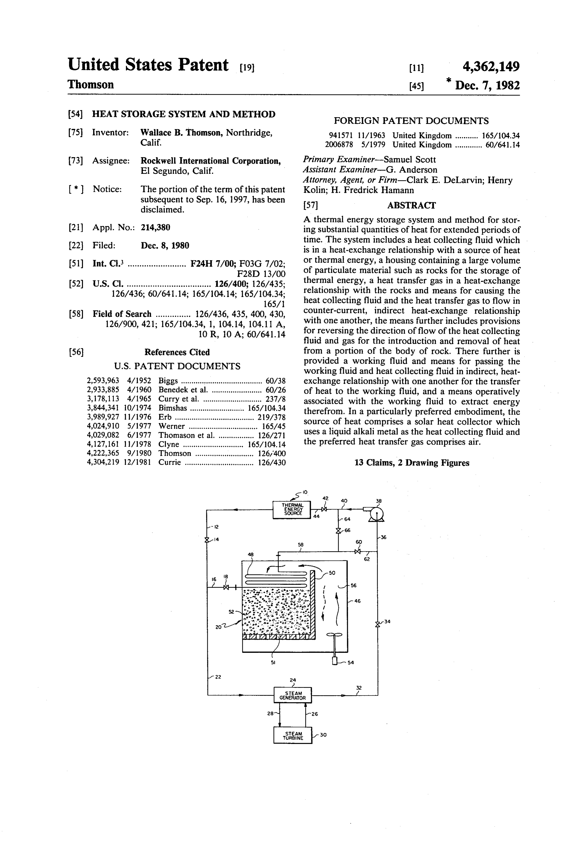
A thermal energy storage system and method for stor (21) Appl. No.: 214,380 ing substantial quantities of heat for extended periods of 22 Filed: Dec. 8, 1980 time. The system includes a heat collecting fluid which is in a heat-exchange relationship with a source of heat 51) Int. Cl. ......................... F24H 7/00; F03G 7/02; or thermal energy, a housing containing a large volume F28D 13/OO of particulate material such as rocks for the storage of 52) U.S. Cl. .................................... 126/400; 126/435; thermal energy, a heat transfer gas in a heat-exchange 126/436; 60/641.14; 165/104.14; 165/104.34; relationship with the rocks and means for causing the 165/1 heat collecting fluid and the heat transfer gas to flow in (58) Field of Search ............... 126/436, 435, 400, 430, counter-current, indirect heat-exchange relationship 126/900, 421; 165/104.34, 1, 104.14, 104.11 A, with one another, the means further includes provisions 10 R, 10 A; 60/641.14 for reversing the direction of flow of the heat collecting fluid and gas for the introduction and removal of heat (56) References Cited from a portion of the body of rock. There further is
working fluid and heat collecting fluid in indirect, heat 2,593,963 4/1952 Biggs ....................................... 60/38 exchange relationship with one another for the transfer 2,933,885 4/1960 Benedek et al ... 60/26 of heat to the working fluid, and a means operatively 3,178,113 4/1965 Curry et al. .. ... 237/8 associated with the working fluid to extract energy 3,844,34 10/1974 Binnshas.... 165/104.34 therefrom. In a particularly preferred embodiment, the 3,989,927 11/1976 Erb ........ ... 219/378 4,024,910 5/1977 Werner ................................. 165/45 source of heat comprises a solar heat collector which 4,029,082 6/1977 Thomason et al. .. ... 126/271 uses a liquid alkali metal as the heat collecting fluid and 4,127,161 11/1978 Clyne ................... 165/104.14 the preferred heat transfer gas comprises air. 4,222,365 9/1980 Thomson ... ... 126'400 4,304,219 12/1981 Currie ................................. 126/430 13 Claims, 2 Drawing Figures
THERMA
ENERGY
source
GENERATOR
TuRNE
Page 2
Drawing sheet — no readable text.
Page 3
Drawing sheet — no readable text.
Page 4
suitable for use, for example, by a commercial utility
HEAT STORAGE SYSTEMAND METHOD power plant.
U.S. Pat. No. 2,933,885 discloses a heat storage accu
CROSS-REFERENCE TO RELATED mulator system which comprises a closed loop circuit APPLICATIONS 5 containing a heat transmitting fluid and including an This application is related to application Ser. No. isolated heat accumulator for the circuit. The heat accu 912,678, filed June 5, 1978, which was issued Sept. 16, mulator contains a heat absorbent medium having a 1980, as U.S. Pat. No. 4,222,365. melting point between the low and high temperature limits of the fluid in the closed loop circuit.
FIELD OF THE INVENTION O U.S. Pat. No. 3,178,113 discloses a heat storage sys The present invention relates to the storage of heat in tem particularly adapted to space installations. The system is made up of two interconnecting systems, one substantial quantities over relatively long periods of of time. The invention particularly relates to the collection agewhich constitutes an energy absorber and heat stor and storage of solar heat for use in a utility power plant. 15 sionand release unit, and the other comprises a conver system by which the heat is converted to electric
BACKGROUND ART ity. The collection and storage system includes a heat With the advent of the energy crisis there has been energy collector or convertor for collecting heat from substantial emphasis placed on the utilization of the The boilerofisthein sun the rays
which are reflected onto a boiler.
circuit which includes a heat storage so-called "non-exhaustible' sources of energy such as 20 device. The system also includes appropriate valves and solar heat. One of the principal problems associated controllers for maintaining a substantially constant, with effective utilization of solar heat has been the cost of storing significant quantities of such heat for use desired temperature in the circuit. during non-daylight hours or during extended periods power U.S. Pat. No. 2,593,963 relates to a binary cycle plant and utilizes a high melting point tertiary when the sun was obscured by cloudy or overcast skies. 25 fluid for indirect heating. The proposed system, how Indeed, the high cost of construction of storage systems ever, does not provide for the storage of heat, though it has minimized the effective utilization of solar heat. In general, large volumes of storage media are absolutely does suggest the use of a liquid alkali metal as a fluid heat transfer medium.
essential. At the present time, the cost of providing storage devices of adequate size has proved to be a o thisOther patents considered during the preparation of application but not considered sufficiently pertinent limiting factor in the utilization of solar heat for other to warrant further discussion are U.S. Pat. Nos. than small scale domestic or residential space and water 2,680,437; 3,983,929; 3,957,030; 3,968,653; 3,977, 197; heating applications. 3,993,041; and 4,038,555.
A typical residential system for the utilization of solar energy is shown in U.S. Pat. No. 4,029,082. The system is SUMMARY OF THE INVENTION comprises a storage bin containing heat storage material In accordance with the present invention, there is and a means for channeling air in sequence from a space provided a thermal energy storage system and a method to be warmed through the storage bin to pick up heat at for storing substantial quantities of heat over extended a low temperature. The warm air is returned to the periods of time. The present invention is applicable to space to be warmed. Patentees further suggest the addi- 40 excess heat from, for example, a nuclear reactor or a tion of water to the air and the storage bin to act as an conventional coal-fired furnace. The present invention, additional source of heat storage as well as providing however, is particularly suited for use with a solar ther humidity to the air. mal energy source such as the large scale central receiv U.S. Pat. No. 3,989,927 describes another heat stor ers proposed for supplying heat to an electric utility age system for use in space heating which comprises a 45 plant. Broadly, the system comprises a heat collecting container having walls formed of a heat resistant mate fluid in heat-exchange relationship with a source of rial and including a guide duct in the form of a tube heat, a housing containing a large volume of particulate extending through the container for carrying a gaseous material such as rocks for the storage of thermal energy, heat extraction medium. The container also contains a heat transfer gas in a heat-exchange relationship with heat storage medium comprising heavy metal bearing 50 the rocks and a means for causing the heat collecting minerals in the form of a pourable bulk of particulate fluid and the heat transfer gas to flow in a counter-cur solids suitable for directly contacting with air to be rent, indirect, heat-exchange relationship with one an heated for places of human habitation. other. Such means further includes provisions for re U.S. Pat. No. 4,024,910 discloses a system for the versing the direction of flow of the heat collecting fluid storage of heat or cold to be utilized in maintaining a 55 and the heat transfer gas for the introduction and re desired temperature in habital areas. The system utilizes moval of heat from the body of rocks. There further is a plurality of channels dug directly into the earth and provided a working fluid and a means for passing the filled with rocks which are used to absorb heat or cold working fluid and heat collecting fluid in indirect, heat for storage; a part of the storage being the rocks them exchange relationship with one another for the transfer selves and usually a much larger part being the adjacent 60 of heat from the heat collecting fluid to the working earth. Suitable conduit connections are provided for fluid to extract energy therefrom.
carrying heat or cold to the rocks. In accordance with the present method, a heat col The foregoing systems, while of interest for residen lecting fluid is passed in heat-exchange relationship tial space heating or even space heating of commercial with the source of heat such as a solar receiver and buildings, do not address the problem faced by a utility 65 thereafter is passed in a counter-current, indirect, heat industry where a high temperature heat source is re exchange relationship with a heat transfer gas to receive quired. Thus, others have developed systems in an at from or transmit heat to the heat transfer gas. The heat tempt to provide a heat storage system which would be transfer gas in turn is passed through a bed of rocks. The
Page 5
direction of flow of the heat transfer gas and heat col are the silicone oils and terphenyls. Exemplary inor lecting fluid are reversible such that heated heat transfer ganic salts utilizable in a molten state include NaoH--- gas is always introduced or withdrawn from an upper Na2CO3, NaOH.--NaNO3, (LiNaK)2CO3, Na2CO3--- portion of the bed of rocks. Further, the volume of the BacO3, MgCl2 + NaCl-KCl, LiCO3--CaCO3, NaCl bed of rocks and flow rate of the heat transfer gas are -- Na2CO3, Na2CO3, NaCl--CaCl2, KNO3 + NaNO3, adjusted such that the apparent velocity of the gas flow KNO3--NaNO3 + NaNO2, NaOH, NaNO3, CaCl2, ing through the bed is within the range of from about 0 KCl, NaCl, KF, NaF, KOH, LiCO3. A preferred inor to 6 feet per second. The height of the bed preferably is ganic salt is a mixture of KNO3 and NaNO3 with or such as to provide an average residence time of gas without NaNO2.
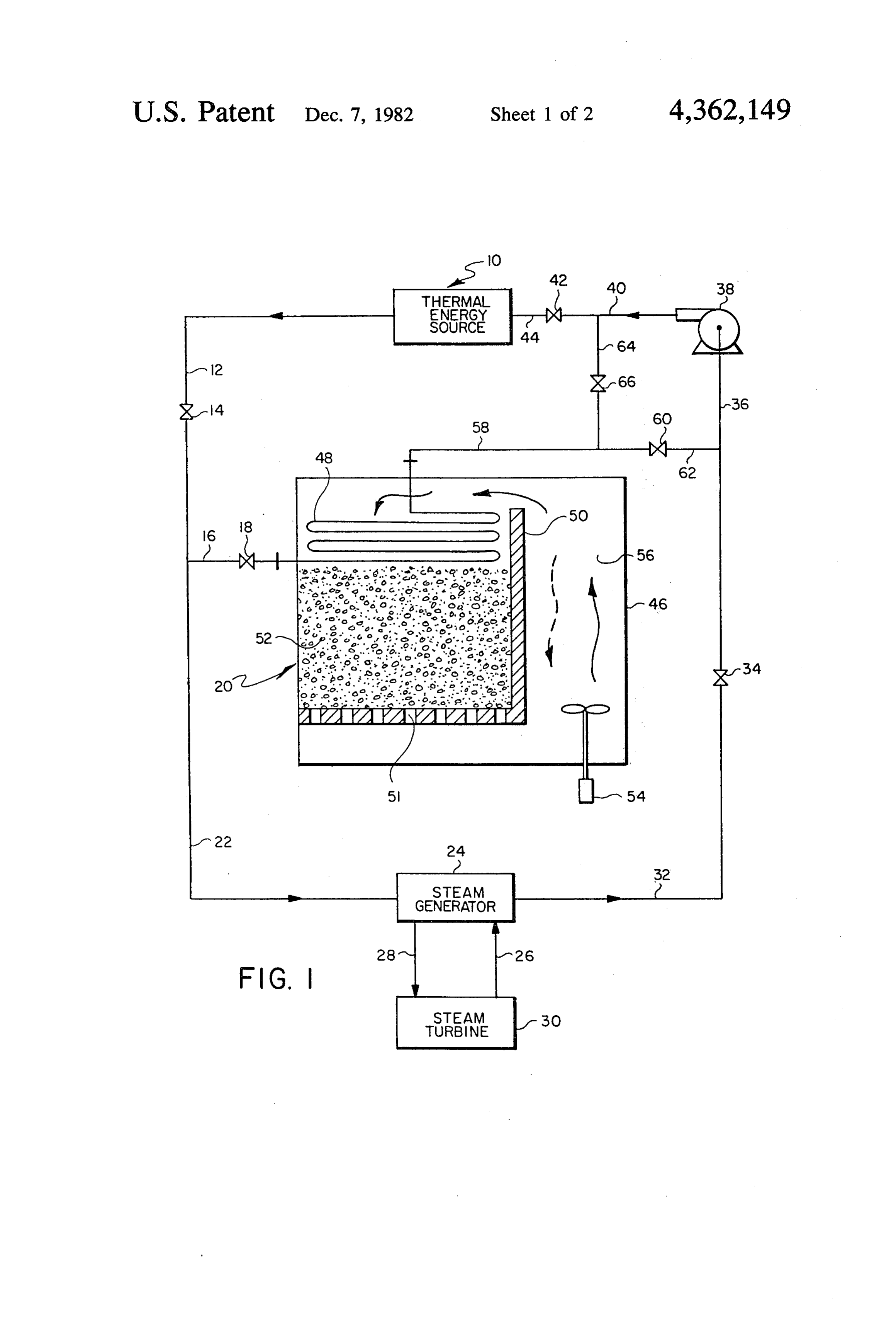
within the bed of from about 1 to 100 seconds. Prefera 10 During the hours of peak solar insolation, the system bly, the rocks have a median diameter of from about 1 is sized such that there is an excess of thermal energy to 5 centimeters. collected by thermal energy source 10. The heat col In accordance with a particularly preferred embodi lecting fluid is withdrawn via a conduit 12, a valve 14, ment wherein the source of heat comprises a solar heat a conduit 16, and a valve 18 for introduction into a collector, the heat collecting fluid is a liquid alkali 15 thermal energy storage system 20. Valve 18 is adjusted metal, the heat transfer gas is air, and the working fluid such that only the excess heat collecting fluid passes is water which is converted to steam. It has been found into the storage system. The balance of the heat collect that by utilizing a bed of rocks, it is possible to store ing fluid passes through a conduit 22 for introduction thermal energy which is recoverable at temperatures in into a steam generator 24. In the steam generator 24, the a range of from 600 to 1600 F. or even higher. Fur 20 heat collecting fluid passes in indirect, heat exchange ther, contrary to popular opinion, it has been found that relationship with a source of a working fluid such as it is not necessary to use exotic gases or high pressures water introduced through a conduit 26. Depending for the recovery of significant quantities of heat from upon the particular application, again, a variety of fluids the rocks, rather, ordinary air is utilizable at or near could be used. However, in accordance with this partic atmospheric pressure. In some applications, it may be 25 ularly preferred embodiment, the working fluid is wa desirable to locate the storage system below grade with ter. The water is heated to steam which is withdrawn a thick layer of soil resting on top of the rock bed re via a conduit 28 for introduction into a steam turbine 30, gion. At the expense of additional excavation and care wherein the thermal energy is converted to mechanical ful sealing of the storage boundaries, the rock bed gas energy. The mechanical energy can be used for many coolant could operate well above atmospheric pressure 30 purposes. However, in accordance with this particular with significant reduction in the heat exchanger size and preferred embodiment, the mechanical energy is uti cost. These and numerous other advantages of the pres lized to drive a generator (not shown) to produce elec ent invention will be more clear with reference to the tricity. The heat collecting fluid passing through the following description of the invention. steam generator 24 is returned to a pump 38 via a con 35 duit 32, a valve 34, and a conduit 36. The heat collecting
DESCRIPTION OF THE DRAWINGS fluid is discharged from the pump38 and returned to the FIG. 1 is a schematic of a preferred embodiment of thermal energy source 10 via a conduit 40, a valve 42 the system of the present invention; and and a conduit 44.
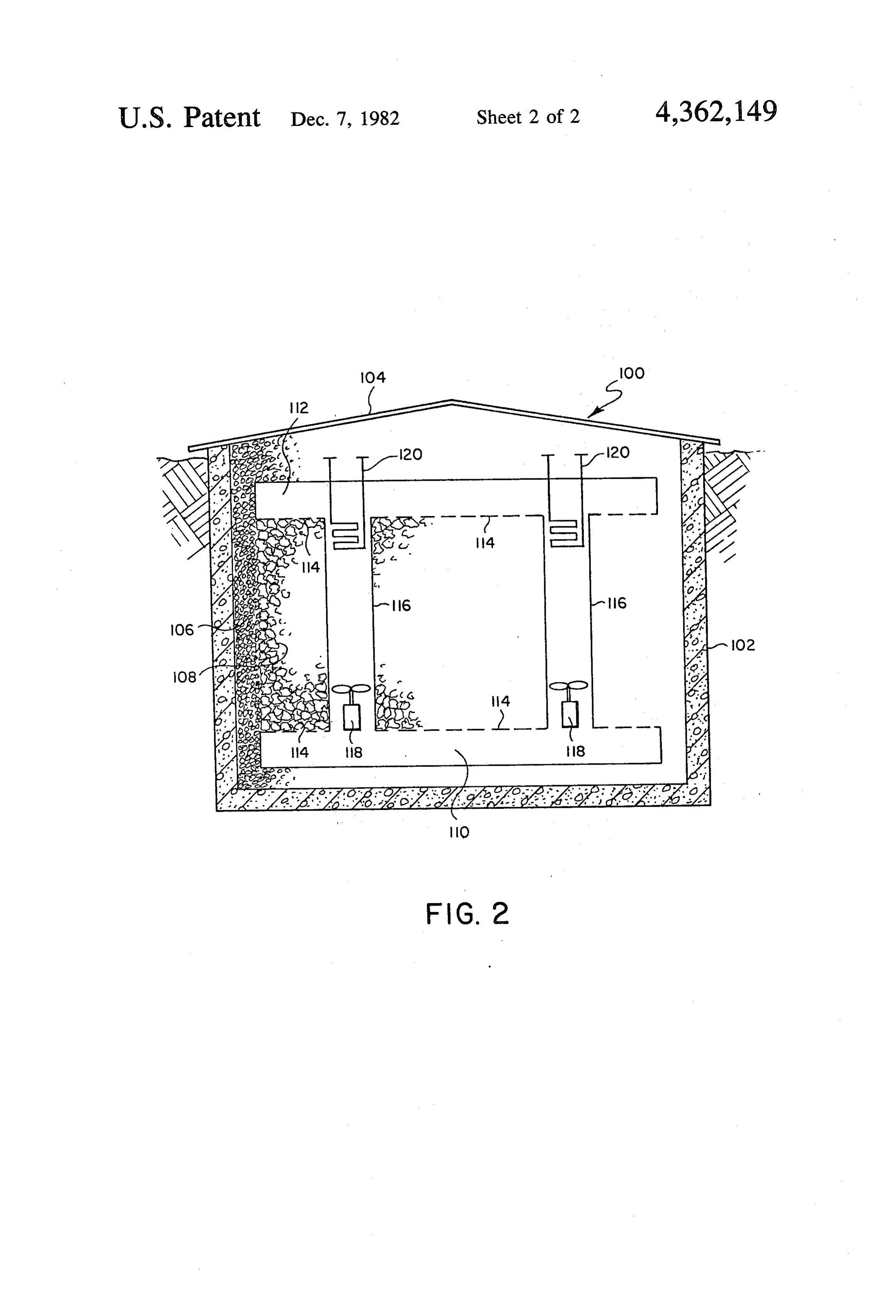
FIG. 2 is a pictorial drawing in cross section of a The heat storage system 20 comprises an outer hous preferred embodiment of the heat storage subsystem of 40 ing 46 within which is contained a heat exchanger coil the present invention. 48, and an inner housing 50 having a bottom portion which is perforated with a plurality of openings 51 for
PREFERRED EMBODIMENT the passage of air therethrough. The housing 50 also For convenience, the present invention will be de contains a bed of particulate heat storage material 52. It scribed with reference to the particularly preferred 45 is an advantage of the present invention that suitable embodiment, namely, its use for the storage of solar heat storage materials are inexpensive and readily avail thermal energy. Referring to FIG. 1, there is provided able solid particulates such as rocks. Typical rocks suit a thermal energy source 10 such as a central solar col able for use in the present invention are granite, lime lector wherein the sun's energy is collected and focused stone, syenite, basalt, dolomite, volcanic rock and blast on a heat exchanger commonly referred to as a receiver 50 furnace slag. The size of the solid particles is not partic through which passes a heat collecting fluid. ularly critical. However, it is generally preferred that A variety of materials are utilizable for the heat col they have a median diameter of from about 0.5 to 15 lecting fluid in accordance with the present invention. centimeters and a particularly preferred range is from Suitable materials include gases, liquid metals, molten about 1 to 5 centimeters. The shape of the rocks also is inorganic salts and numerous organic coolants. The 55 not critical and the random shapes and sizes obtained selection of a suitable fluid for a particular application is from a conventional rock milling or rock crushing appa well within the skill of those versed in the art. Examples ratus are generally satisfactory. It is particularly desired of suitable gases include air, nitrogen, helium and argon for a system in accordance with the present invention, or combinations of such gases. Exemplary liquid metals that the pressure drop through the bed of rocks be less are sodium, potassium, mixtures of sodium and potas 60 than 0.2 psi and preferably less than about 0.1 psi, since sium, and mixtures of lead and bismuth. A particularly a high pressure drop requires more power to push air preferred heat collecting liquid metal is sodium, because through the bed with a corresponding loss in system of its thermal properties. Exemplary organic coolants efficiency.
are mixtures of diphenyl and diphenyl oxide, hexa The pressure drop through the bed 52 is, of course, a fluorobenzene, phenyl methyl polysiloxane, partially 65 function of the velocity of the gases passing there hydrogenated terphenyls, polychlorinated biphenyls, through, the height of the bed, and the size and shape of polyphenyl ethers, aliphatic oils, silicone oils, toluene the rocks. However, it is well within the skill of one and mixtures of terphenyls. Preferred organic coolants versed in this art to adjust these parameters to obtain the
Page 6
desired pressure drop. It is a critical parameter of the become unreasonably high. In large-tank storage sys present invention that the velocity of the air flowing tems it is then usually considered necessary to dissipate through the bed of rocks not be excessive. Thus, it is the pressure of the heat transfer fluid before it arrives at essential that the apparent velocity of the gas flowing the storage tanks. The equipment needed to dissipate through the bed of rocks not exceed about 6 feet per the pressure, the additional pump capability to pump second and, preferably, be within the range of from the fluid back up the tower, and the pumping power about 2 to 3 feet per second. The term "apparent veloc required to do this, all impose penalties on tank-type ity' refers to the velocity the gases would have assum storage systems.
ing they were flowing uniformly throughout the cross Referring now to FIG. 2, therein is depicted in cross sectional area of the bed. - - s 10 sectional view a schematic of a preferred heat storage The heat storage system 20 further includes a means subsystem 100 of the present invention. The subsystem for circulating air through the bed of rocks and a heat comprises an outer housing formed by walls 102 and the exchanger coil 48. In the drawing, the means for circu top 104 is a body of insulating material 106 such as lating air is depicted as a fan assembly 54, which circu porous slag, cinders and volcanic rock. A large bed of lates air through a duct 56 defined generally by the 15 heat storage rock 108 also is located within the outer walls of the housing 20 and the container 50. The fan housing in an area bounded by a lower duct 110 and an assembly 54 is provided with a reversible motor upper duct 112. Each of these ducts is provided with a whereby in operation it can force the air to circulate plurality of openings 114 on the side of the duct facing upwardly through the duct 56 and down across the heat the heat storage material 108. The subsystem further exchanger coil 48 then through the bed 52. Alterna 20 includes two vertical ducts 116, each of which contain tively, it can be reversed to cause the air to flow up a reversible fan assembly 118 and a heat exchanger coil wardly through the openings 51, the bed 52, across the 120.
heat exchanger coil 48 and back into the duct 56. The In a system designed, for example, to store about 800 heat exchanger coil 48 is connected to the inlet of the to 1600 megawatt hours of thermal energy, the outer pump 38 via a conduit 58 and a valve 60. The discharge 25 housing would comprise a square approximately 275 conduit 40 from the pump 38 is interconnected to heat feet to the side and about 45 feet high. There also would exchanger coil 48 via a conduit 64, a valve 66 and con be provided approximately 12 sets of the ducts 116, heat duit 58. exchange coils 120, and fan assemblies 118, each set It will be readily apparent to those versed in the art being substantially evenly spaced throughout the length that the system of the present invention is capable of 30 of the outer housing. In such an embodiment, the ducts operation in several modes. More particularly, in a di preferably are formed from inexpensive concrete pipe rect mode when there is only sufficient thermal energy and would be, for example, about 4 feet in diameter. available to supply the requirements of the steam gener The walls for such a system also could readily be ator 24 and the steam turbine 30, valves 18, 64 and 60 formed from concrete and would have a nominal thick are closed and valves 14, 34 and 42 are open, such that 35 ness of from about 6 to 9 inches. The roof member 104 all the heat collecting fluid travels from the thermal could be formed from corrugated sheet metal such as energy source 10 through conduits 12 and 22 to the iron or aluminum. Thus, it is seen that the system of the steam generator 24 and is discharged via conduits 40 present invention is readily fabricated using inexpensive and 44. materials. Further, the length of the duct required in the When there is an excess of thermal energy over that embodiment depicted is substantially minimized, thus required by the steam generator 24, a portion of the heat reducing the cost of the duct, heat losses and reducing collecting fluid is passed to the heat storage system 20 the fan requirements.
via conduit 16 and valve 18 where it flows upwardly The twenty-four fan assemblies in the ducts described through the heat exchanger coil 48 in indirect, counter would circulate air at atmospheric pressure at the rate current, heat-exchange relationship with the air which 45 of about three million cubic feet per minute. Such a absorbs heat therefrom and then passes downwardly system is capable of supplying sufficient thermal energy through the rock bed 52. The bed 52 absorbs the heat to provide all the heat requirements for a 100-megawatt for later use. electric utility plant for a period of from about 3 to 6 When there is insufficient heat available for the ther hours when the rocks are at a temperature of from about mal energy source 10, the fan assembly 54 is operated in 50 600-1600' F. Obviously, additional subsystems could a reverse direction such that the air flows upwardly be provided to supply heat for further extended periods through the openings 51, the bed 52, and through the of time to provide a heat storage system which could heat exchanger coil 48. Valve 60 is closed and valve 66 readily provide all the thermal requirements of the util is opened so the heat collecting fluid discharged from ity plant during non-daylight hours. It will be appreci the pump 38 flows through conduits 40, 64, and 58 into 55 ated that the configuration depicted is not critical and the upper end of the heat exchanger coil assembly 48 indeed, in some instances, a rectangular or round hous such that again the air and heat collecting fluid pass in ing might be preferred. Further, the location of the fan countercurrent, indirect, heat-exchange relationship and heat exchanger with the ducts could readily be with one another. The hot heat collecting fluid is dis altered. It will also be obvious that the present invention charged via valve 18 and conduit 16 for passage to the could be built in modules of varying desired sizes. steam generator 24 via conduit 22. Multiple storage systems also could be utilized such A feature of this storage system when used with a that heat could be introduced into one while it was solar central receiver is that a tube-and-fin heat ex being withdrawn from another. changer is ideally suited to contain the high static pres It will be appreciated that the particular embodiments sure caused by the coolant circulating to an elevated 65 depicted are illustrative only, and various configura tower. This pressure is usually not tolerable in conven tions and arrangements of equipment are possible. In tional liquid-media, large-tank storage systems because deed, in actual practice there would be many more the large tanks require such thick walls that the costs valves as well as instrumentation lines and controllers
Page 7
for automatic operation. However, the placement of 8. The system of claim 5 wherein the organic coolant such additional equipment and selection of such acces is selected from the group consisting of silicone oil and sories is a matter of design choice and well within the terphenyls.
skill of one versed in the art. 9. The system of claim 1 wherein said heat transfer What is claimed is: gas is air.
1. A thermal energy storage system comprising: 10. The system of claim 1 wherein said rocks have a a source of heat for heating a heat collecting fluid to median diameter of from about 1 to 5 cm. a temperature within the range of from about 600 11. The system of claim 1 wherein said working fluid to 1600. F.; is water.
a housing containing a bed of rocks for storage of O 12. The system of claim 1 wherein said first-named thermal energy; means further provides for the introduction and with a heat transfer gas in heat-exchange relationship with drawal of heated heat transfer gas from an upper por said bed of rocks; tion of said bed of rocks.
means for moving said heat transfer gas through said 13. A method of storing and recovering thermal en bed of rocks at an apparent velocity of less than 15 ergy comprising:
about 6 ft/sec; providing a source of heat and a heat collecting fluid; means for causing said heat collecting fluid and said passing the heat collecting fluid in a heat-exchange heat transfer gas to flow in counter-current, indi relationship with the source of heat; rect, heat-exchange relationship with one another, providing a housing containing a bed of rocks for said means including means for reversing the direc- 20 storage of thermal energy and a heat transfer gas in tion of flow of said heat collecting fluid and said direct heat-exchange relationship with said bed of heat transfer gas; rocks;
a working fluid; passing said heat collecting fluid and said heat trans means for passing said working fluid and said heat fer gas in a counter-current, indirect, heat collecting fluid in indirect, heat-exchange relation 25 exchange relationship with one another, said heat ship with one another; and collecting fluid and said heat transfer gas being means operatively associated with said working fluid maintained at a temperature within a range of from to convert thermal energy contained therein to about 600 to 1600. F.;
mechanical energy. passing said heat transfer gas through said bed of 2. The system of claim 1 wherein the heat collecting 30 rocks at an apparent velocity not to exceed about 6 fluid is a gas. ft/sec;
3. The system of claim 1 wherein the heat collecting reversing the direction of the flow of said heat col fluid is a liquid metal. lecting fluid and said heat transfer gas such that 4. The system of claim 1 wherein the heat collecting heated gas is introduced or withdrawn from an fluid is a molten inorganic salt. 35 upper portion of said bed of rocks; 5. The system of claim 1 wherein the heat collecting providing a working fluid;
fluid is an organic coolant. passing said working fluid and said heat collecting 6. The system of claim 2 wherein the gas is selected fluid in heat exchange-relationship with one an from the group consisting of air and helium. other to transfer heat to the working fluid; and 7. The system of claim 4 wherein the inorganic salt 40 extracting energy fromk said
heated
working fluid.
comprises a mixture of KNO3 and NaNO3.
Provenance
- Collection
- Cited prior art
- Original PDF
- patentimages.storage.googleapis.com →
- Filed
- 1980-12-08
- Pages
- 7
- Method
- pdftotext (the PDF's own text layer) + pdftoppm 300dpi page scans
- Source
- Google Patents bibliographic record
- Granted
- 1982-12-07
- Inventors
- Wallace B. Thomson; Rockwell International Corp
- Transcribed from
- patentimages.storage.googleapis.com →