patent · US20080223443A1
Optical concentrator, especially for solar photovoltaics
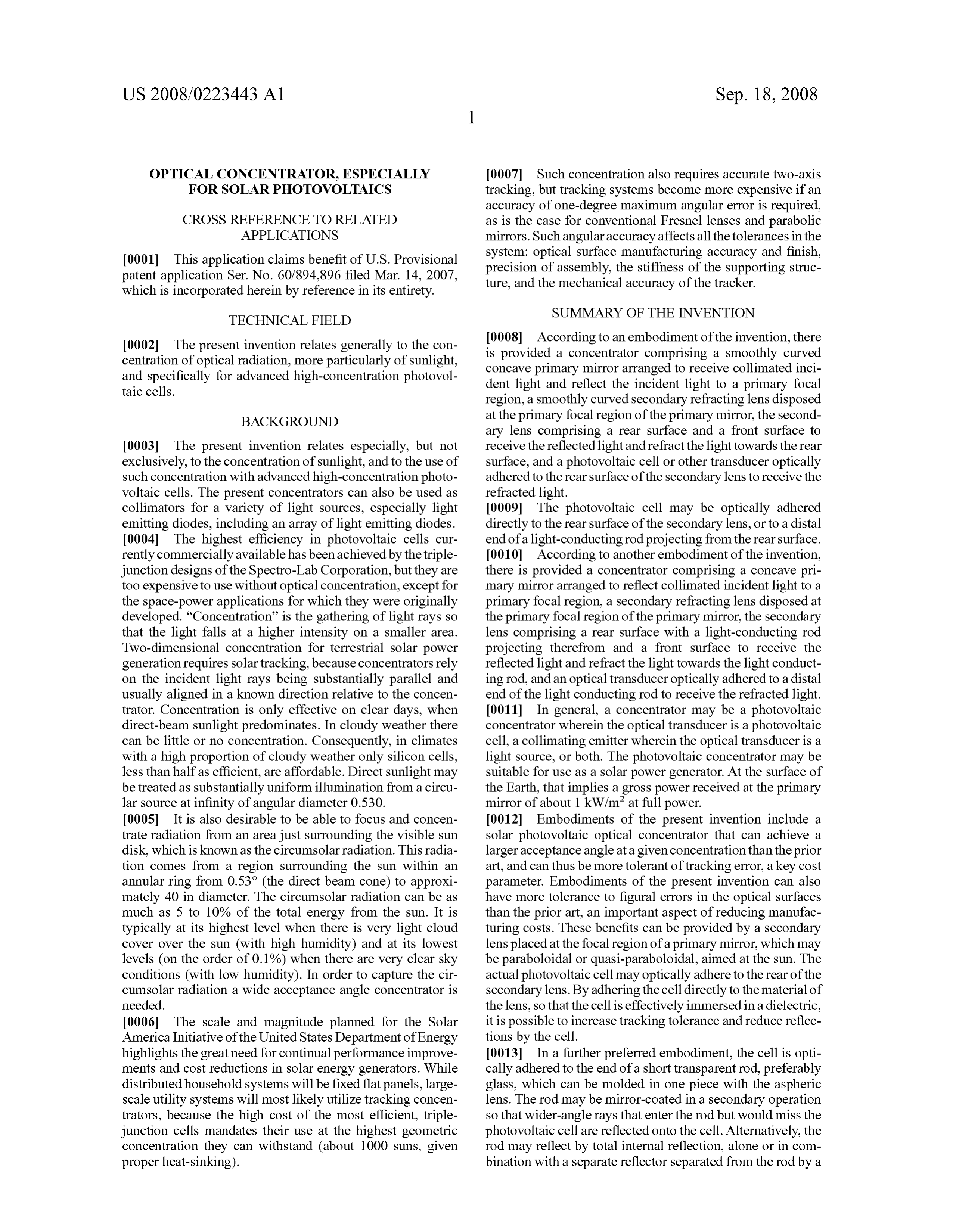
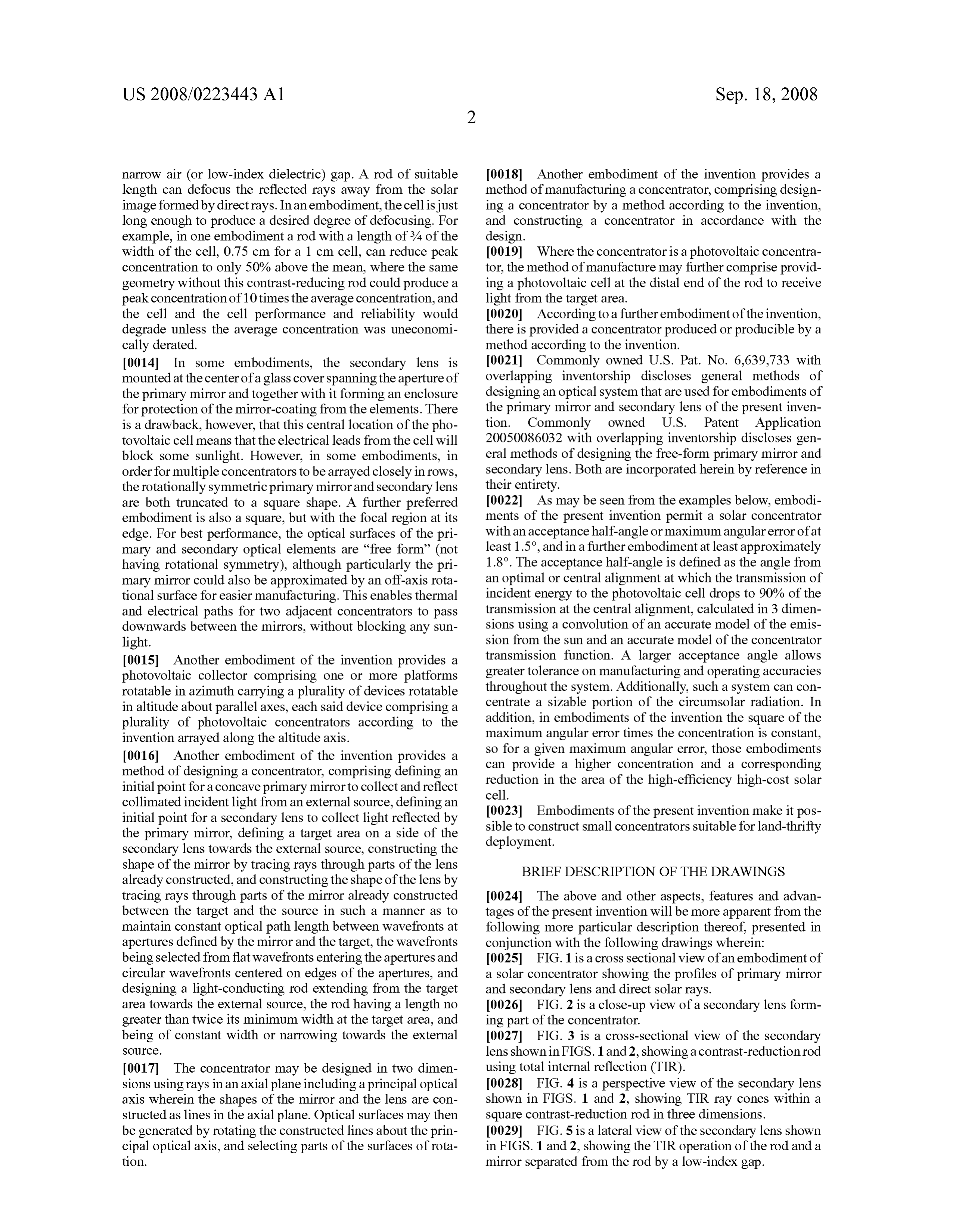
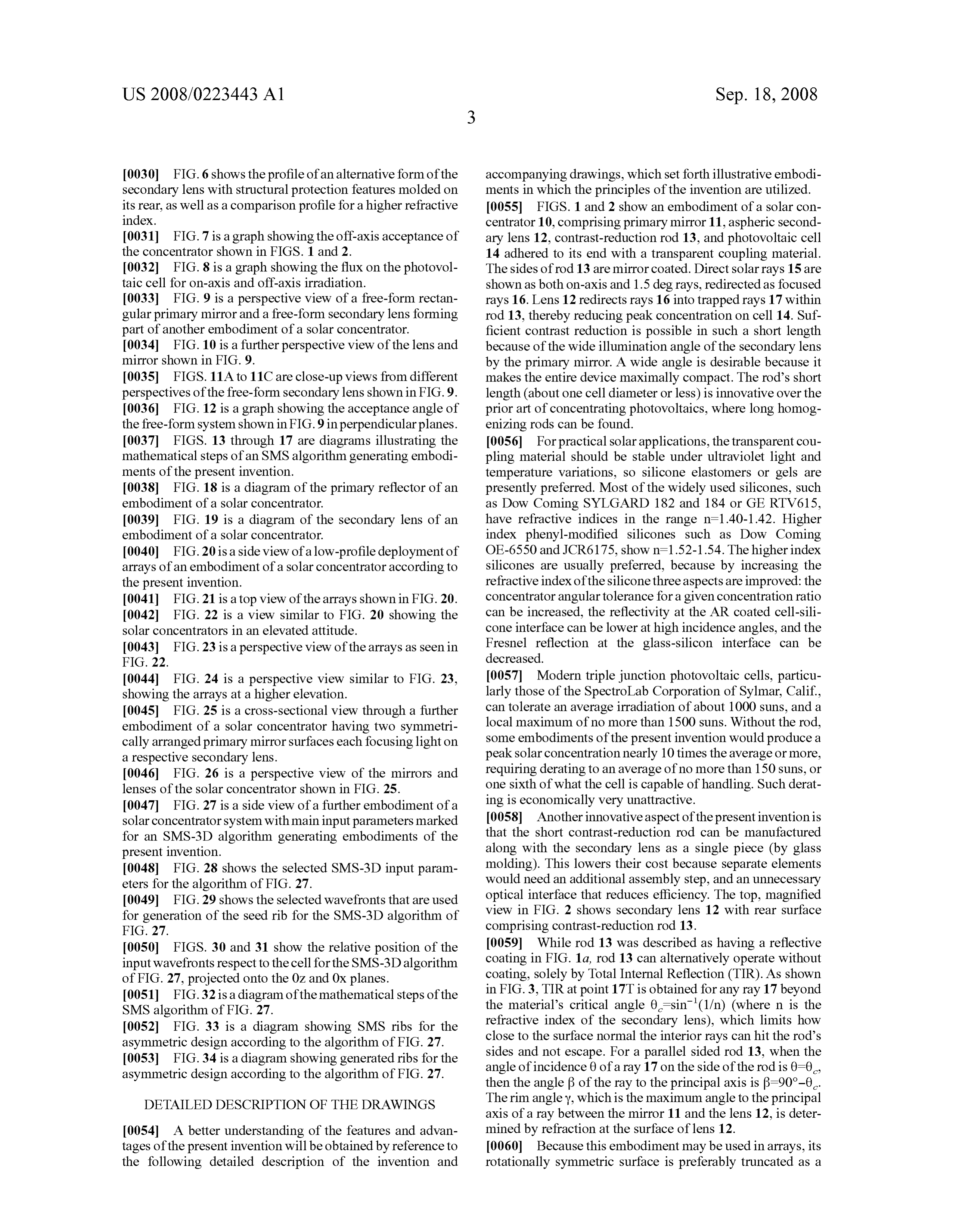
18 September 2008
Page 1 — bibliographic record
(19) United States (12) Patent Application Publication (10) Pub. No.: US 2008/0223443 A1
Benitez et al. (43) Pub. Date: Sep. 18, 2008 (54) OPTICAL CONCENTRATOR, ESPECIALLY Related U.S. Application Data
FOR SOLAR PHOTOVOLTACS
(60) Provisional application No. 60/894,896, filed on Mar.
(75) Inventors: Pablo Benitez, Madrid (ES); Juan Publication Classification Carlos Minano, Madrid (ES);
Maikel Hernandez, Madrid (ES); (51) nt. Cl.
Aleksandra Cvetkovic, Madrid HOIL 3L/0232 (2006.01)
(ES); William A. Parkyn, Lomita, G()2B I ZA()() (2006.01)
CA (US) (52) U.S. Cl. .…. 136/259; 35.9/727
Correspondence Address: (57) ABSTRACT
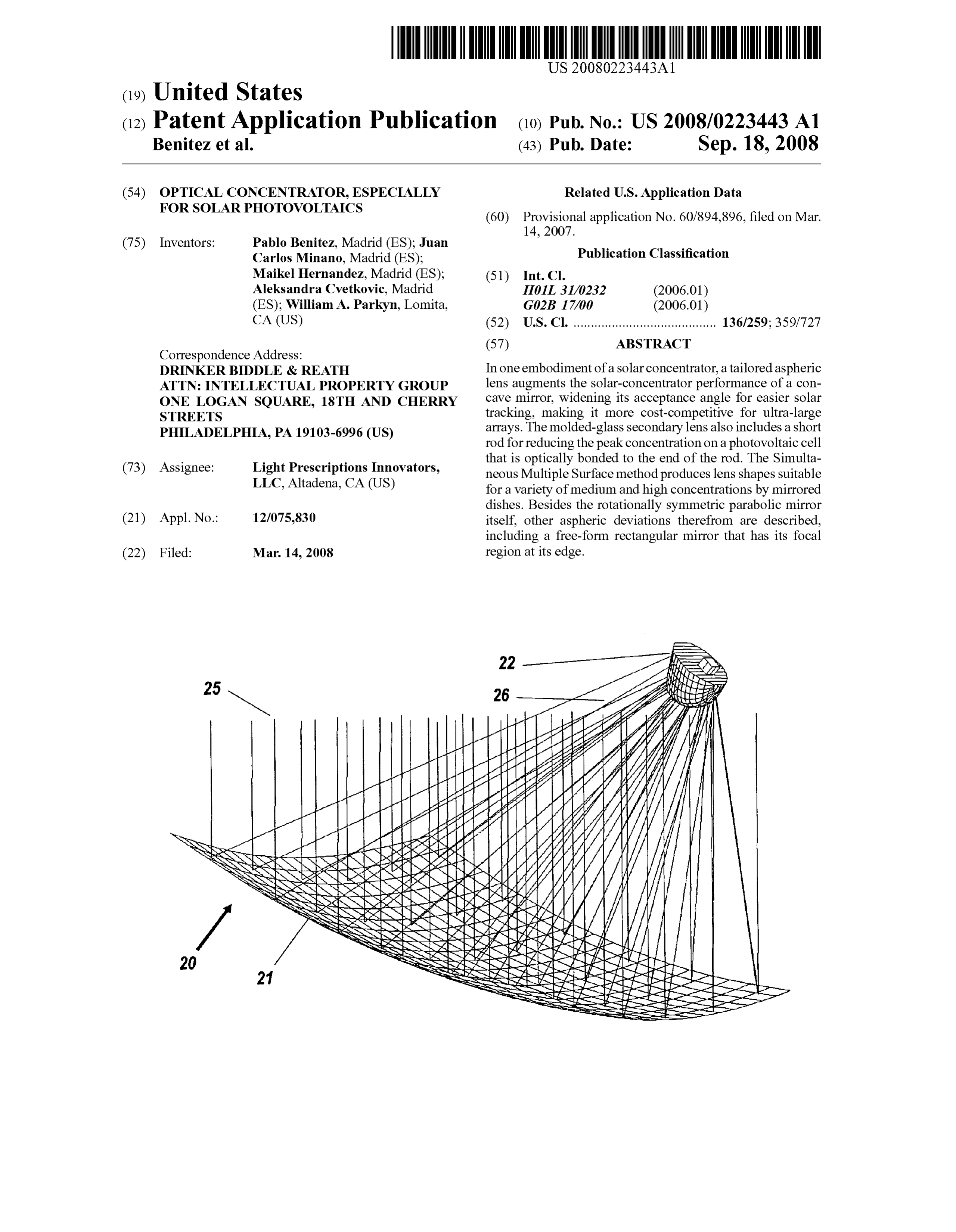
DRINKER BDDLE & REATH In one embodiment of a Solar concentrator, a tailored aspheric ATTN INTELLECTUAL PROPERTY GROUP lens augments the solar-concentrator performance of a con ONE LOGAN SQUARE, 18TH AND CHERRY cave mirror, widening its acceptance angle for easier Solar STREETS tracking, making it more cost-competitive for ultra-large PHILADELPHIA, PA 19103-6996 (US) arrays. The molded-glass secondary lens also includes a short rod for reducing the peak concentration on a photovoltaic cell that is optically bonded to the end of the rod. The Simulta (73) Assignee: Light Prescriptions Innovators, neous Multiple Surface method produces lens shapes suitable LLC. Altadena, CA (US) for a variety of medium and high concentrations by mirrored dishes. Besides the rotationally symmetric parabolic mirror (21) Appl. No.: 12/075,830 itself, other aspheric deviations therefrom are described, including a free-form rectangular mirror that has its focal (22) Filed: Mar. 14, 2008 region at its edge.
stress
Page 2
Drawing sheet — no readable text.
Page 3
Drawing sheet — no readable text.
Page 4
Drawing sheet — no readable text.
Page 5
Drawing sheet — no readable text.
Page 6
Drawing sheet — no readable text.
Page 7
Drawing sheet — no readable text.
Page 8
Patent Application Publication Sep. 18, 2008 Sheet 7 of 17 US 2008/0223443 A1 -3 -2.5 -2 -15 -1 -0.5 O O5 1 1.5 2 2.5 3 - - acceptance, x section - - - acceptance, y section
Page 9
Drawing sheet — no readable text.
Page 10
Drawing sheet — no readable text.
Page 11
Drawing sheet — no readable text.
Page 12
Drawing sheet — no readable text.
Page 13
Drawing sheet — no readable text.
Page 14
Drawing sheet — no readable text.
Page 15
Drawing sheet — no readable text.
Page 16
Drawing sheet — no readable text.
Page 17
Drawing sheet — no readable text.
Page 18
Drawing sheet — no readable text.

Page 19
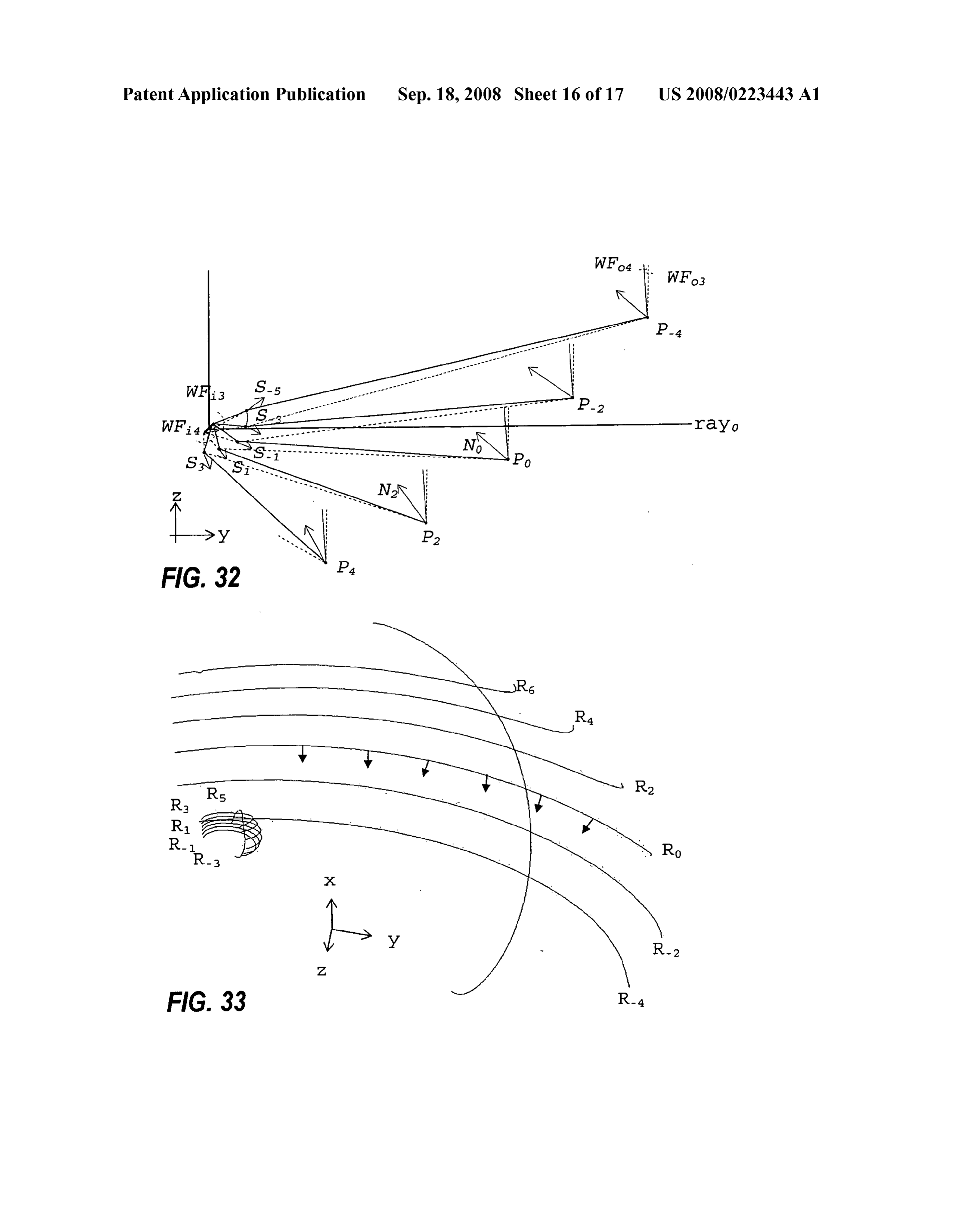
US 2008/0223443 A1 Sep. 18, 2008
OPTICAL CONCENTRATOR, ESPECIALLY 0007 Such concentration also requires accurate two-axis FOR SOLAR PHOTOVOLTACS tracking, but tracking systems become more expensive if an accuracy of one-degree maximum angular error is required,
CROSS REFERENCE TO RELATED as is the case for conventional Fresnel lenses and parabolic APPLICATIONS mirrors. Such angular accuracy affects all the tolerances in the 0001. This application claims benefit of U.S. Provisional system: optical Surface manufacturing accuracy and finish, patent application Ser. No. 60/894,896 filed Mar. 14, 2007, precision of assembly, the stiffness of the Supporting struc which is incorporated herein by reference in its entirety. ture, and the mechanical accuracy of the tracker.
SUMMARY OF THE INVENTION
TECHNICAL FIELD
0002 The present invention relates generally to the con 0008 According to an embodiment of the invention, there centration of optical radiation, more particularly of Sunlight, is provided a concentrator comprising a Smoothly curved and specifically for advanced high-concentration photovol concave primary mirror arranged to receive collimated inci taic cells. dent light and reflect the incident light to a primary focal region, a Smoothly curved secondary refracting lens disposed
BACKGROUND at the primary focal region of the primary mirror, the second ary lens comprising a rear Surface and a front Surface to 0003. The present invention relates especially, but not receive the reflected light and refract the light towards the rear exclusively, to the concentration of Sunlight, and to the use of Surface, and a photovoltaic cell or other transducer optically Such concentration with advanced high-concentration photo adhered to the rear surface of the secondary lens to receive the Voltaic cells. The present concentrators can also be used as refracted light.
collimators for a variety of light sources, especially light 0009. The photovoltaic cell may be optically adhered emitting diodes, including an array of light emitting diodes. directly to the rear surface of the secondary lens, or to a distal 0004. The highest efficiency in photovoltaic cells cur end of a light-conducting rod projecting from the rear Surface. rently commercially available has been achieved by the triple 0010. According to another embodiment of the invention, junction designs of the Spectro-Lab Corporation, but they are there is provided a concentrator comprising a concave pri too expensive to use without optical concentration, except for mary mirror arranged to reflect collimated incident light to a the space-power applications for which they were originally primary focal region, a secondary refracting lens disposed at developed. “Concentration” is the gathering of light rays so the primary focal region of the primary mirror, the secondary that the light falls at a higher intensity on a smaller area. lens comprising a rear Surface with a light-conducting rod Two-dimensional concentration for terrestrial solar power projecting therefrom and a front Surface to receive the generation requires Solar tracking, because concentrators rely reflected light and refract the light towards the light conduct on the incident light rays being Substantially parallel and ing rod, and an optical transducer optically adhered to a distal usually aligned in a known direction relative to the concen end of the light conducting rod to receive the refracted light. trator. Concentration is only effective on clear days, when 0011. In general, a concentrator may be a photovoltaic direct-beam Sunlight predominates. In cloudy weather there concentrator wherein the optical transducer is a photovoltaic can be little or no concentration. Consequently, in climates cell, a collimating emitter wherein the optical transducer is a with a high proportion of cloudy weather only silicon cells, light source, or both. The photovoltaic concentrator may be less than half as efficient, are affordable. Direct sunlight may Suitable for use as a Solar power generator. At the Surface of be treated as substantially uniform illumination from a circu the Earth, that implies a gross power received at the primary lar source at infinity of angular diameter 0.530. mirror of about 1 kW/m at full power. 0005. It is also desirable to be able to focus and concen 0012 Embodiments of the present invention include a trate radiation from an area just Surrounding the visible Sun Solar photovoltaic optical concentrator that can achieve a disk, which is known as the circumsolar radiation. This radia larger acceptance angle at a given concentration than the prior tion comes from a region Surrounding the Sun within an art, and can thus be more tolerant of tracking error, a key cost annular ring from 0.53° (the direct beam cone) to approxi parameter. Embodiments of the present invention can also mately 40 in diameter. The circumsolar radiation can be as have more tolerance to figural errors in the optical Surfaces much as 5 to 10% of the total energy from the sun. It is than the prior art, an important aspect of reducing manufac typically at its highest level when there is very light cloud turing costs. These benefits can be provided by a secondary cover over the sun (with high humidity) and at its lowest lens placed at the focal region of a primary mirror, which may levels (on the order of 0.1%) when there are very clear sky be paraboloidal or quasi-paraboloidal, aimed at the Sun. The conditions (with low humidity). In order to capture the cir actual photovoltaic cell may optically adhere to the rear of the cum Solar radiation a wide acceptance angle concentrator is secondary lens. By adhering the cell directly to the material of needed. the lens, so that the cell is effectively immersed in a dielectric, 0006. The scale and magnitude planned for the Solar it is possible to increase tracking tolerance and reduce reflec America Initiative of the United States Department of Energy tions by the cell.
highlights the great need for continual performance improve 0013. In a further preferred embodiment, the cell is opti ments and cost reductions in Solar energy generators. While cally adhered to the end of a short transparent rod, preferably distributed household systems will be fixed flat panels, large glass, which can be molded in one piece with the aspheric scale utility systems will most likely utilize tracking concen lens. The rod may be mirror-coated in a secondary operation trators, because the high cost of the most efficient, triple so that wider-angle rays that enter the rod but would miss the junction cells mandates their use at the highest geometric photovoltaic cell are reflected onto the cell. Alternatively, the concentration they can withstand (about 1000 Suns, given rod may reflect by total internal reflection, alone or in com proper heat-sinking). bination with a separate reflector separated from the rod by a
Page 20
US 2008/0223443 A1 Sep. 18, 2008
narrow air (or low-index dielectric) gap. A rod of suitable 0018. Another embodiment of the invention provides a length can defocus the reflected rays away from the Solar method of manufacturing a concentrator, comprising design image formed by direct rays. In an embodiment, the cell is just ing a concentrator by a method according to the invention, long enough to produce a desired degree of defocusing. For and constructing a concentrator in accordance with the example, in one embodiment a rod with a length of 3/4 of the design.
width of the cell, 0.75 cm for a 1 cm cell, can reduce peak 0019. Where the concentrator is a photovoltaic concentra concentration to only 50% above the mean, where the same tor, the method of manufacture may further comprise provid geometry without this contrast-reducing rod could produce a ing a photovoltaic cell at the distal end of the rod to receive peak concentration of 10 times the average concentration, and light from the target area.
the cell and the cell performance and reliability would 0020. According to a further embodiment of the invention, degrade unless the average concentration was uneconomi there is provided a concentrator produced or producible by a cally derated. method according to the invention. 0014. In some embodiments, the secondary lens is (0021 Commonly owned U.S. Pat. No. 6,639,733 with mounted at the center of a glass cover spanning the aperture of overlapping inventorship discloses general methods of the primary mirror and together with it forming an enclosure designing an optical system that are used for embodiments of for protection of the mirror-coating from the elements. There the primary mirror and secondary lens of the present inven is a drawback, however, that this central location of the pho tion. Commonly owned U.S. Patent Application tovoltaic cell means that the electrical leads from the cell will 2005008.6032 with overlapping inventorship discloses gen block some Sunlight. However, in Some embodiments, in eral methods of designing the free-form primary mirror and order for multiple concentrators to be arrayed closely in rows, secondary lens. Both are incorporated herein by reference in the rotationally symmetric primary mirror and secondary lens their entirety.
are both truncated to a square shape. A further preferred 0022. As may be seen from the examples below, embodi embodiment is also a square, but with the focal region at its ments of the present invention permit a Solar concentrator edge. For best performance, the optical Surfaces of the pri with an acceptance half-angle or maximum angular error of at mary and secondary optical elements are “free form' (not least 1.5°, and in a further embodiment at least approximately having rotational symmetry), although particularly the pri 1.8°. The acceptance half-angle is defined as the angle from mary mirror could also be approximated by an off-axis rota an optimal or central alignment at which the transmission of tional Surface for easier manufacturing. This enables thermal incident energy to the photovoltaic cell drops to 90% of the and electrical paths for two adjacent concentrators to pass transmission at the central alignment, calculated in 3 dimen downwards between the mirrors, without blocking any Sun sions using a convolution of an accurate model of the emis light. sion from the Sun and an accurate model of the concentrator 0015. Another embodiment of the invention provides a transmission function. A larger acceptance angle allows photovoltaic collector comprising one or more platforms greater tolerance on manufacturing and operating accuracies rotatable in azimuth carrying a plurality of devices rotatable throughout the system. Additionally, Such a system can con in altitude about parallel axes, each said device comprising a centrate a sizable portion of the circumsolar radiation. In plurality of photovoltaic concentrators according to the addition, in embodiments of the invention the square of the invention arrayed along the altitude axis. maximum angular error times the concentration is constant, 0016. Another embodiment of the invention provides a So for a given maximum angular error, those embodiments method of designing a concentrator, comprising defining an can provide a higher concentration and a corresponding initial point for a concave primary mirror to collect and reflect reduction in the area of the high-efficiency high-cost Solar cell.
collimated incident light from an external Source, defining an 0023 Embodiments of the present invention make it pos initial point for a secondary lens to collect light reflected by sible to construct small concentrators suitable for land-thrifty the primary mirror, defining a target area on a side of the deployment.
secondary lens towards the external source, constructing the shape of the mirror by tracing rays through parts of the lens BRIEF DESCRIPTION OF THE DRAWINGS already constructed, and constructing the shape of the lens by tracing rays through parts of the mirror already constructed 0024. The above and other aspects, features and advan between the target and the source in Such a manner as to tages of the present invention will be more apparent from the maintain constant optical path length between wavefronts at following more particular description thereof, presented in apertures defined by the mirror and the target, the wavefronts conjunction with the following drawings wherein: being selected from flat wavefronts entering the apertures and [0025] FIG. 1 is a cross sectional view ofan embodiment of circular wavefronts centered on edges of the apertures, and a solar concentrator showing the profiles of primary mirror designing a light-conducting rod extending from the target and secondary lens and direct Solar rays. area towards the external source, the rod having a length no 0026 FIG. 2 is a close-up view of a secondary lens form greater than twice its minimum width at the target area, and ing part of the concentrator.
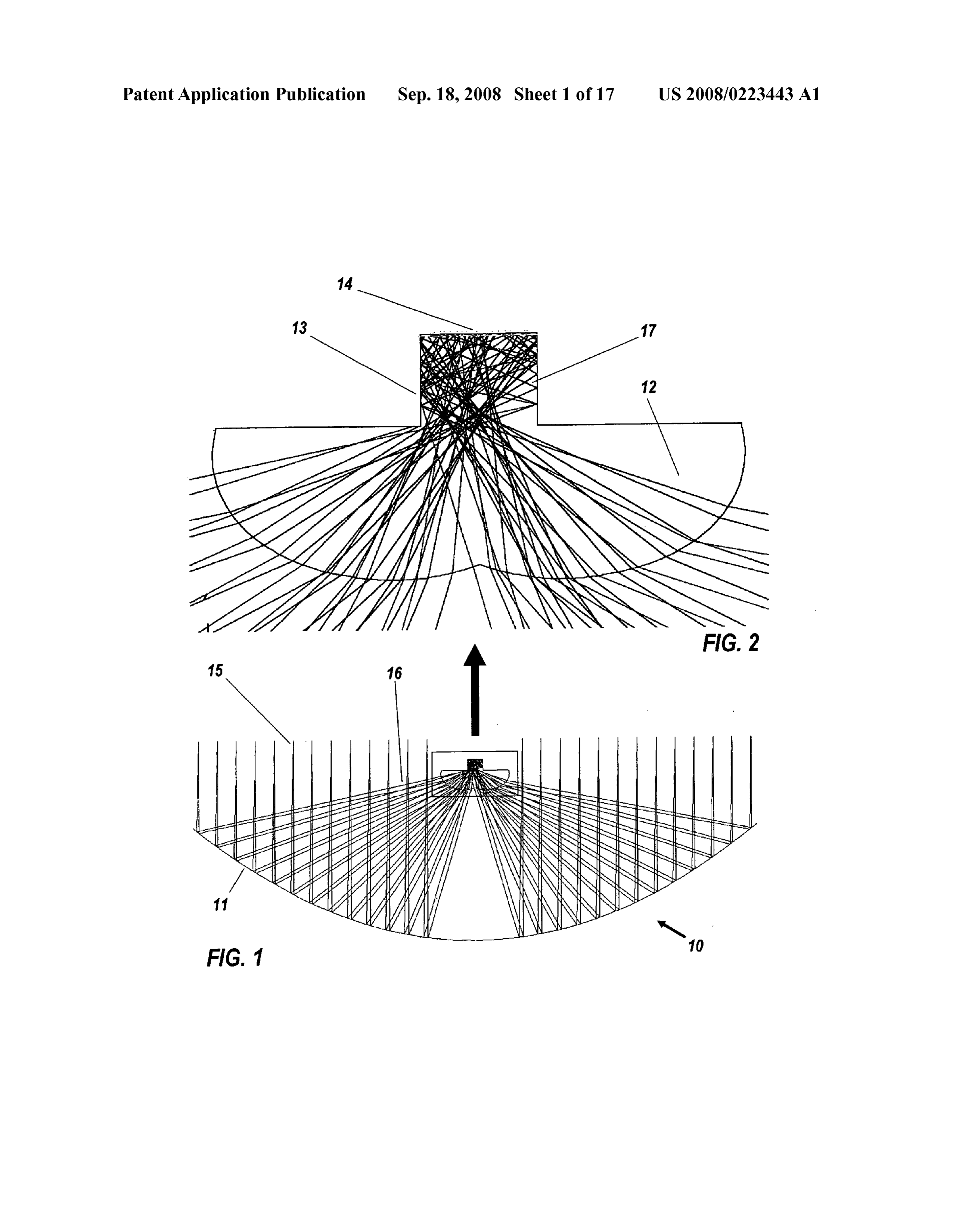
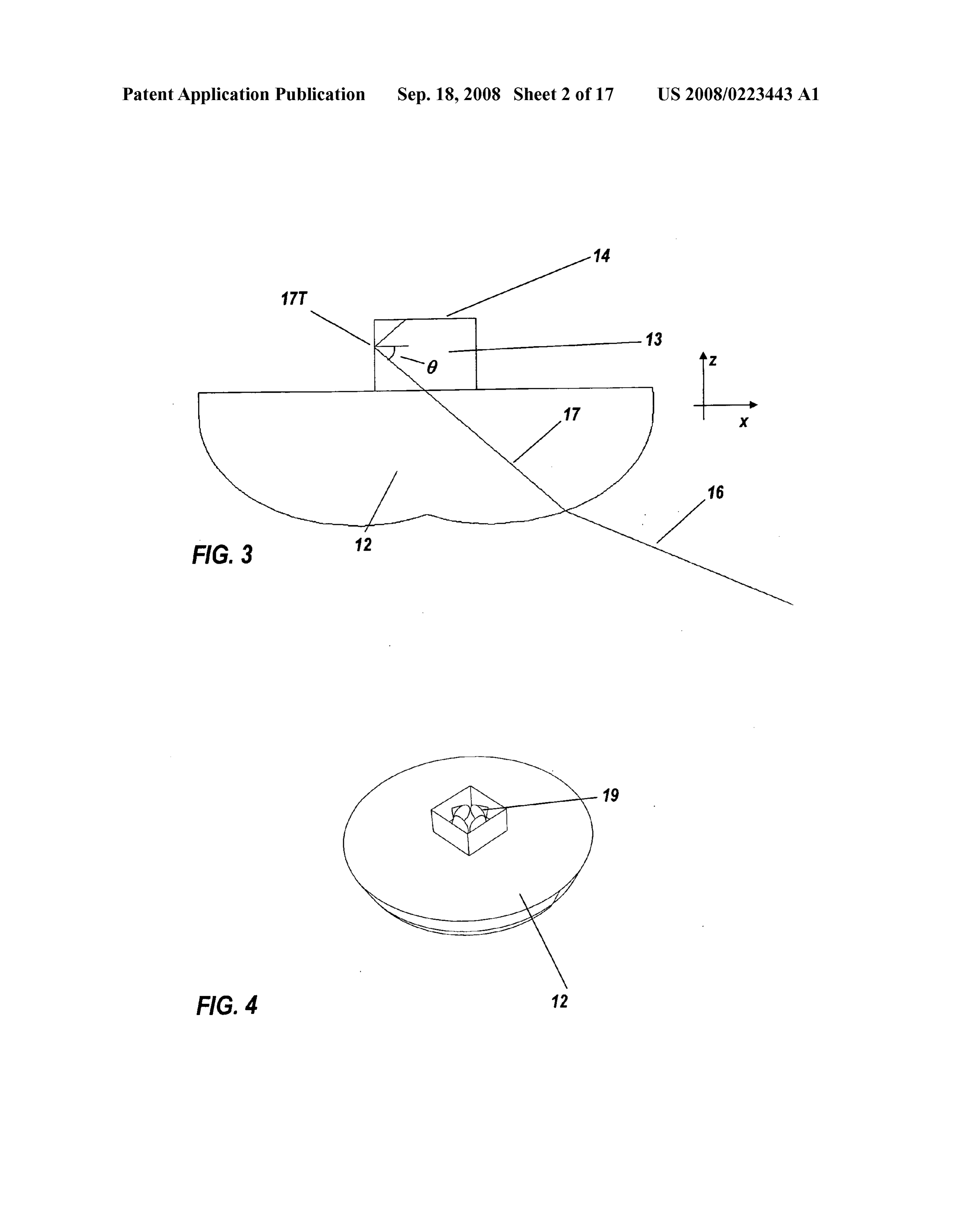
being of constant width or narrowing towards the external 0027 FIG. 3 is a cross-sectional view of the secondary SOUCI. lens shown in FIGS. 1 and 2, showing a contrast-reduction rod 0017. The concentrator may be designed in two dimen using total internal reflection (TIR). sions using rays in an axial plane including a principal optical 0028 FIG. 4 is a perspective view of the secondary lens axis wherein the shapes of the mirror and the lens are con shown in FIGS. 1 and 2, showing TIR ray cones within a structed as lines in the axial plane. Optical Surfaces may then square contrast-reduction rod in three dimensions. be generated by rotating the constructed lines about the prin (0029 FIG. 5 is a lateral view of the secondary lens shown cipal optical axis, and selecting parts of the Surfaces of rota in FIGS. 1 and 2, showing the TIR operation of the rod and a tion. mirror separated from the rod by a low-index gap.
Page 21
US 2008/0223443 A1 Sep. 18, 2008
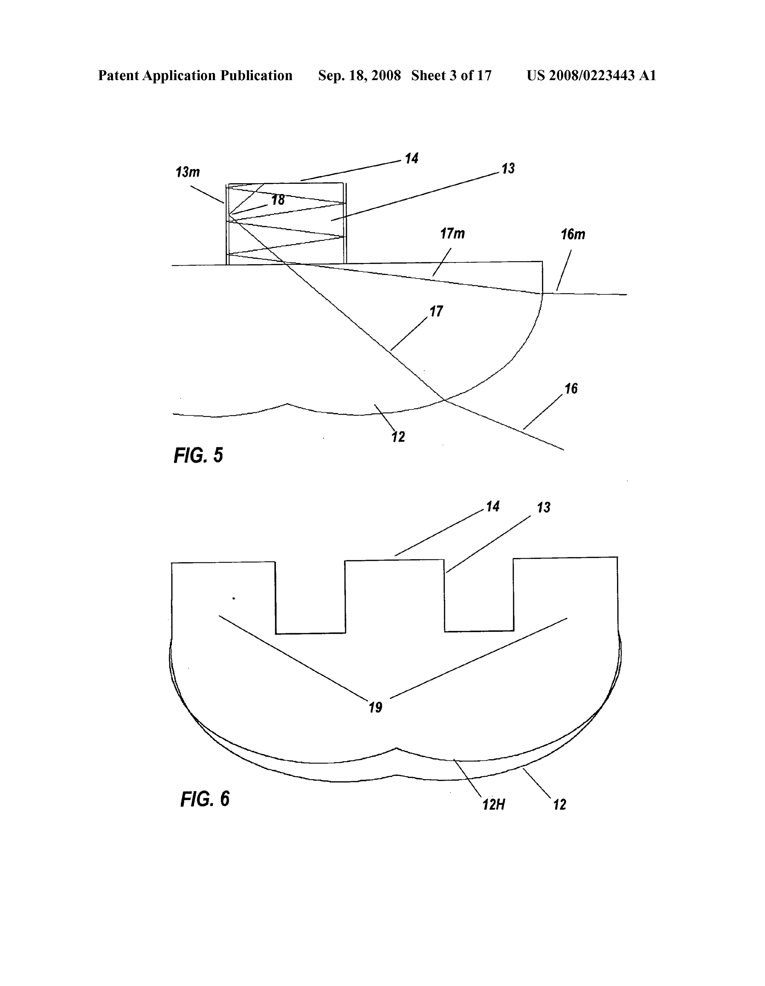
[0030] FIG.6 shows the profile ofan alternative form ofthe accompanying drawings, which set forth illustrative embodi secondary lens with structural protection features molded on ments in which the principles of the invention are utilized. its rear, as well as a comparison profile for a higher refractive 0055 FIGS. 1 and 2 show an embodiment ofa solar con index. centrator 10, comprising primary mirror 11, aspheric second 0031 FIG. 7 is a graph showing the off-axis acceptance of ary lens 12, contrast-reduction rod 13, and photovoltaic cell the concentrator shown in FIGS. 1 and 2. 14 adhered to its end with a transparent coupling material. 0032 FIG. 8 is a graph showing the flux on the photovol The sides of rod 13 are mirror coated. Direct solar rays 15 are taic cell for on-axis and off-axis irradiation. shown as both on-axis and 1.5 degrays, redirected as focused 0033 FIG. 9 is a perspective view of a free-form rectan rays 16. Lens 12 redirects rays 16 into trapped rays 17 within gular primary mirror and a free-form secondary lens forming rod 13, thereby reducing peak concentration on cell 14. Suf part of another embodiment of a Solar concentrator. ficient contrast reduction is possible in Such a short length 0034 FIG. 10 is a further perspective view of the lens and because of the wide illumination angle of the secondary lens mirror shown in FIG. 9. by the primary mirror. A wide angle is desirable because it 0035 FIGS. 11A to 11C are close-up views from different makes the entire device maximally compact. The rod's short perspectives of the free-form secondary lens shown in FIG.9. length (about one cell diameter or less) is innovative over the 0036 FIG. 12 is a graph showing the acceptance angle of prior art of concentrating photovoltaics, where long homog the free-form system shown in FIG.9 in perpendicular planes. enizing rods can be found.
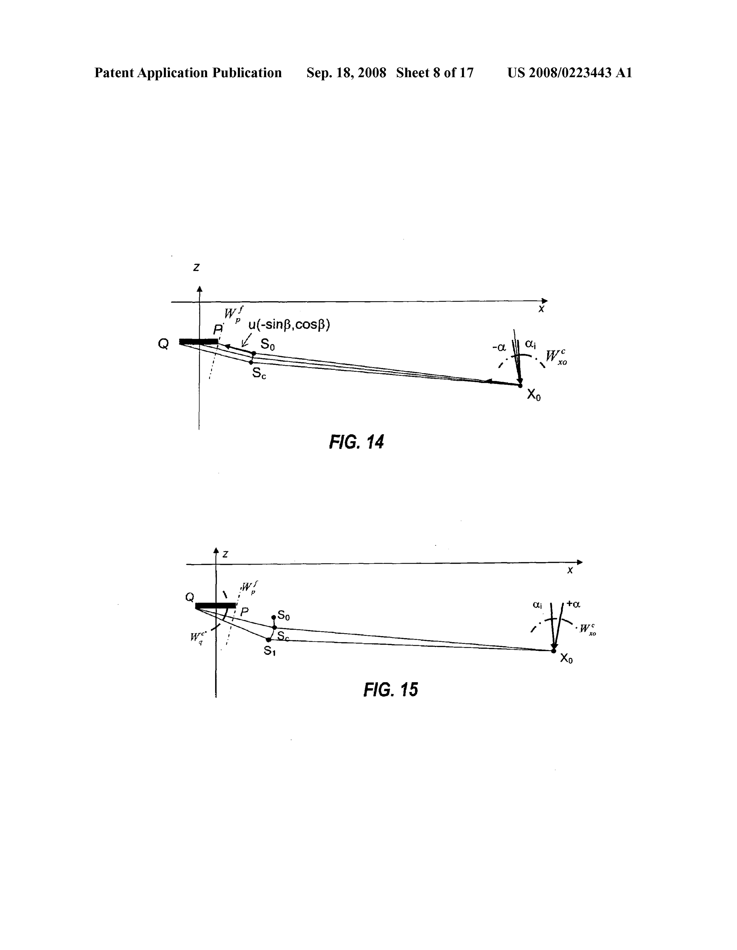
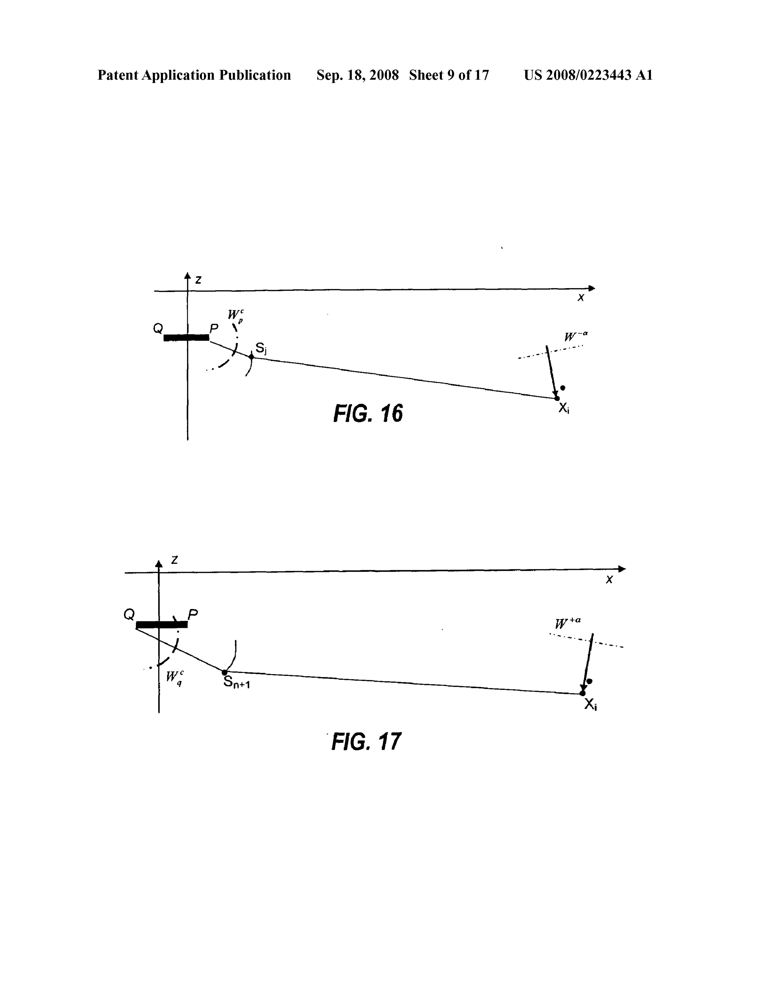
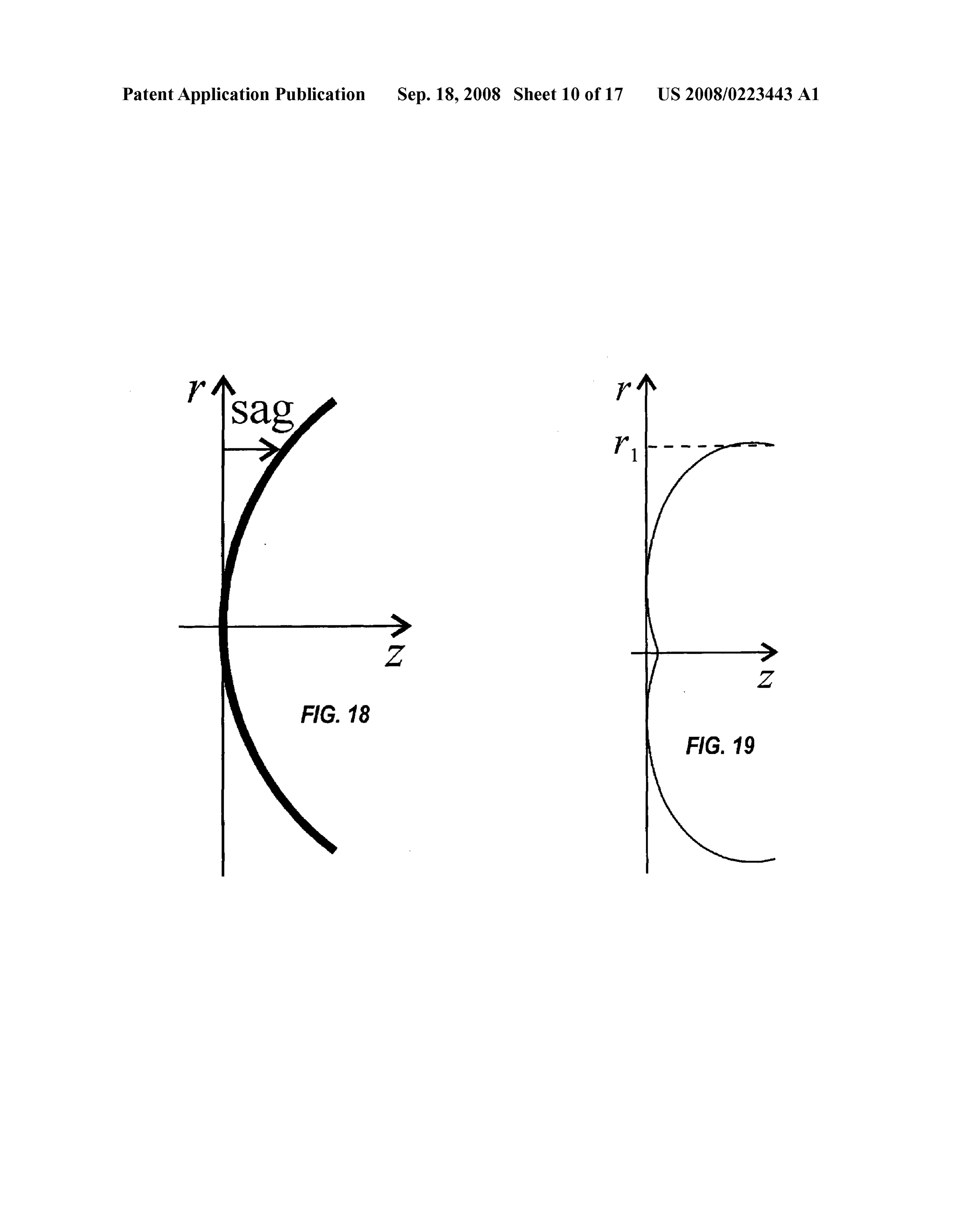
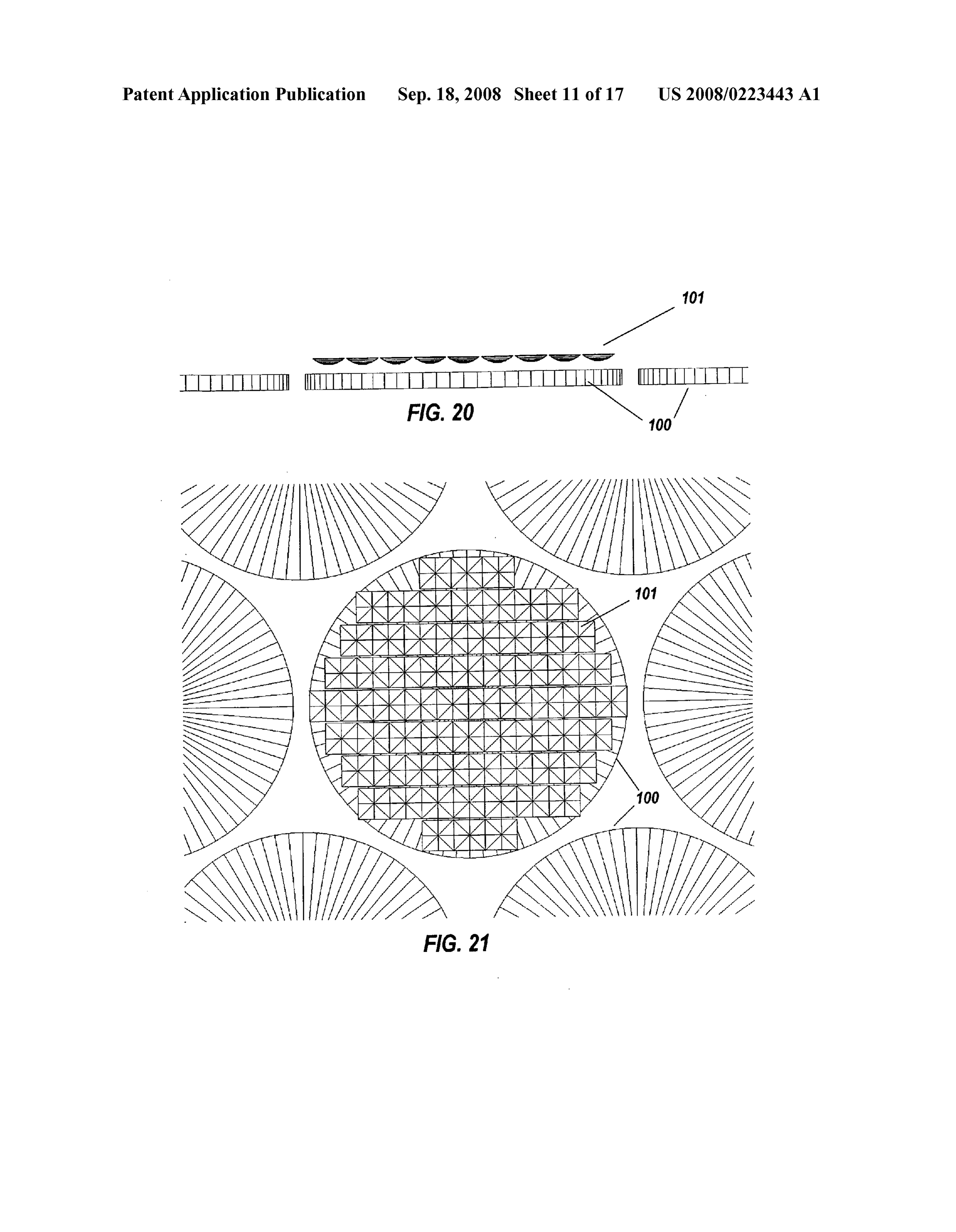
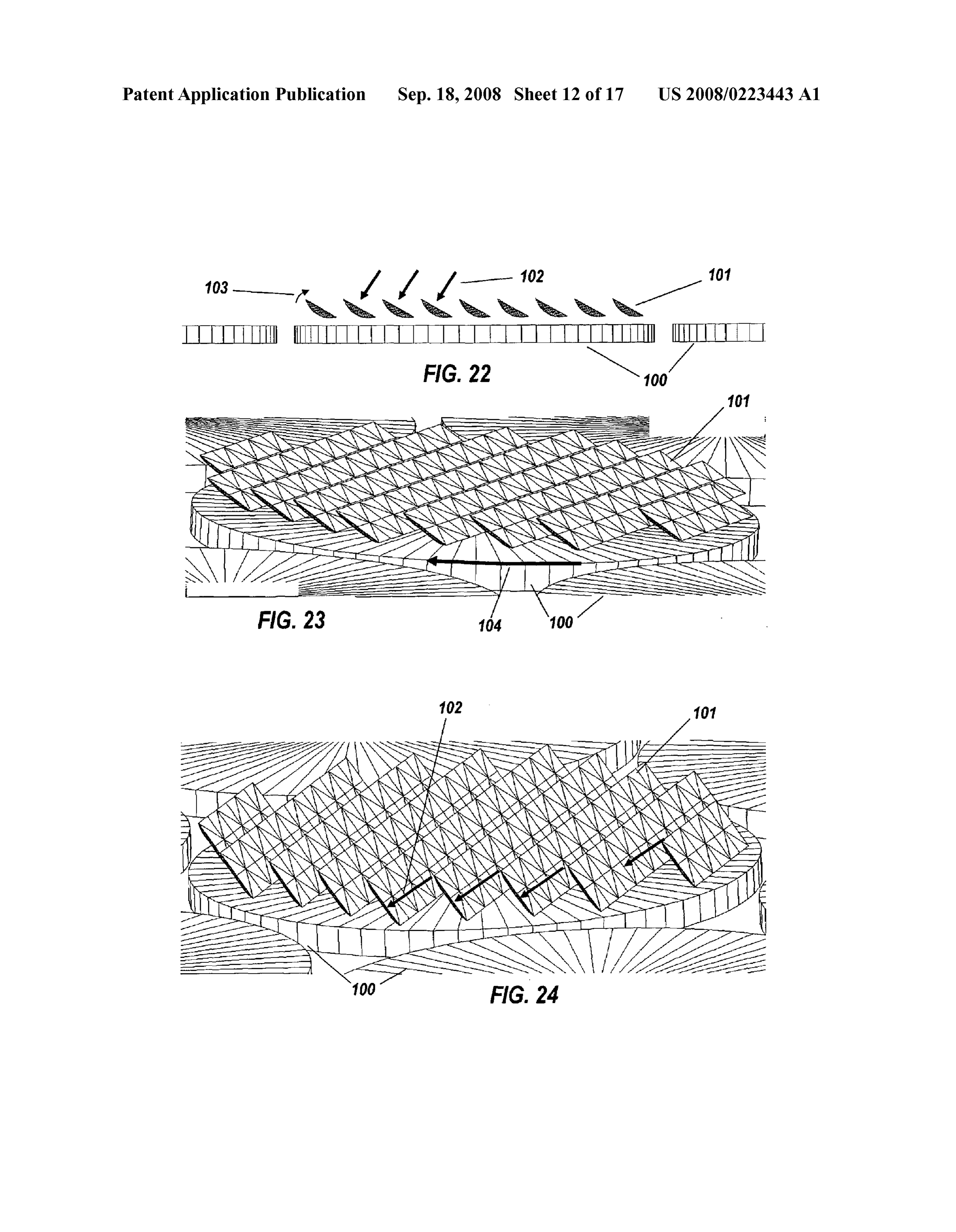
0037 FIGS. 13 through 17 are diagrams illustrating the 0056. For practical solar applications, the transparent cou mathematical steps of an SMS algorithm generating embodi pling material should be stable under ultraviolet light and ments of the present invention. temperature variations, so silicone elastomers or gels are 0038 FIG. 18 is a diagram of the primary reflector of an presently preferred. Most of the widely used silicones, such embodiment of a solar concentrator. as Dow Coming SYLGARD 182 and 184 or GE RTV615, 0039 FIG. 19 is a diagram of the secondary lens of an have refractive indices in the range n=1.40-1.42. Higher embodiment of a solar concentrator. index phenyl-modified silicones such as Dow Coming 0040 FIG.20 is a side view of a low-profile deployment of OE-6550 and JCR6175, show n=1.52-1.54. The higher index arrays of an embodiment of a Solar concentrator according to silicones are usually preferred, because by increasing the the present invention. refractive index of the silicone three aspects are improved: the 004.1 FIG. 21 is a top view of the arrays shown in FIG. 20. concentrator angular tolerance for a given concentration ratio 0042 FIG. 22 is a view similar to FIG. 20 showing the can be increased, the reflectivity at the AR coated cell-sili Solar concentrators in an elevated attitude. cone interface can be lower at high incidence angles, and the 0043 FIG. 23 is a perspective view of the arrays as seen in Fresnel reflection at the glass-silicon interface can be FIG 22. decreased.
0044 FIG. 24 is a perspective view similar to FIG. 23, 0057 Modern triple junction photovoltaic cells, particu showing the arrays at a higher elevation. larly those of the SpectroLab Corporation of Sylmar, Calif., 0045 FIG. 25 is a cross-sectional view through a further can tolerate an average irradiation of about 1000 Suns, and a embodiment of a Solar concentrator having two symmetri local maximum of no more than 1500 Suns. Without the rod, cally arranged primary mirror Surfaces each focusing light on Some embodiments of the present invention would produce a a respective secondary lens. peak Solar concentration nearly 10 times the average or more, 0046 FIG. 26 is a perspective view of the mirrors and requiring derating to an average of no more than 150 Suns, or lenses of the solar concentrator shown in FIG. 25. one sixth of what the cell is capable of handling. Such derat 0047 FIG. 27 is a side view of a further embodiment of a ing is economically very unattractive. Solar concentrator system with main input parameters marked 0.058 Another innovative aspect of the present invention is for an SMS-3D algorithm generating embodiments of the that the short contrast-reduction rod can be manufactured present invention. along with the secondary lens as a single piece (by glass 0048 FIG. 28 shows the selected SMS-3D input param molding). This lowers their cost because separate elements eters for the algorithm of FIG. 27. would need an additional assembly step, and an unnecessary 0049 FIG. 29 shows the selected wavefronts that are used optical interface that reduces efficiency. The top, magnified for generation of the seed rib for the SMS-3D algorithm of view in FIG. 2 shows secondary lens 12 with rear surface FIG. 27. comprising contrast-reduction rod 13. 0050 FIGS. 30 and 31 show the relative position of the 0059 While rod 13 was described as having a reflective input wavefronts respect to the cell for the SMS-3D algorithm coating in FIG. 1a, rod 13 can alternatively operate without of FIG. 27, projected onto the OZ and 0x planes. coating, solely by Total Internal Reflection (TIR). As shown 0051 FIG.32 is a diagram of the mathematical steps of the in FIG. 3, TIR at point 17T is obtained for any ray 17 beyond SMS algorithm of FIG. 27. the material's critical angle 0 sin" (1/n) (where n is the 0052 FIG. 33 is a diagram showing SMS ribs for the refractive index of the secondary lens), which limits how asymmetric design according to the algorithm of FIG. 27. close to the surface normal the interior rays can hit the rod's 0053 FIG. 34 is a diagram showing generated ribs for the sides and not escape. For a parallel sided rod 13, when the asymmetric design according to the algorithm of FIG. 27. angle of incidence 0 of a ray 17 on the side of the rod is 0–0, then the angle B of the ray to the principal axis is f=90°-0.
DETAILED DESCRIPTION OF THE DRAWINGS The rim angley, which is the maximum angle to the principal axis of a ray between the mirror 11 and the lens 12, is deter 0054. A better understanding of the features and advan mined by refraction at the surface of lens 12. tages of the present invention will be obtained by reference to 0060. Because this embodiment may be used in arrays, its the following detailed description of the invention and rotationally symmetric Surface is preferably truncated as a
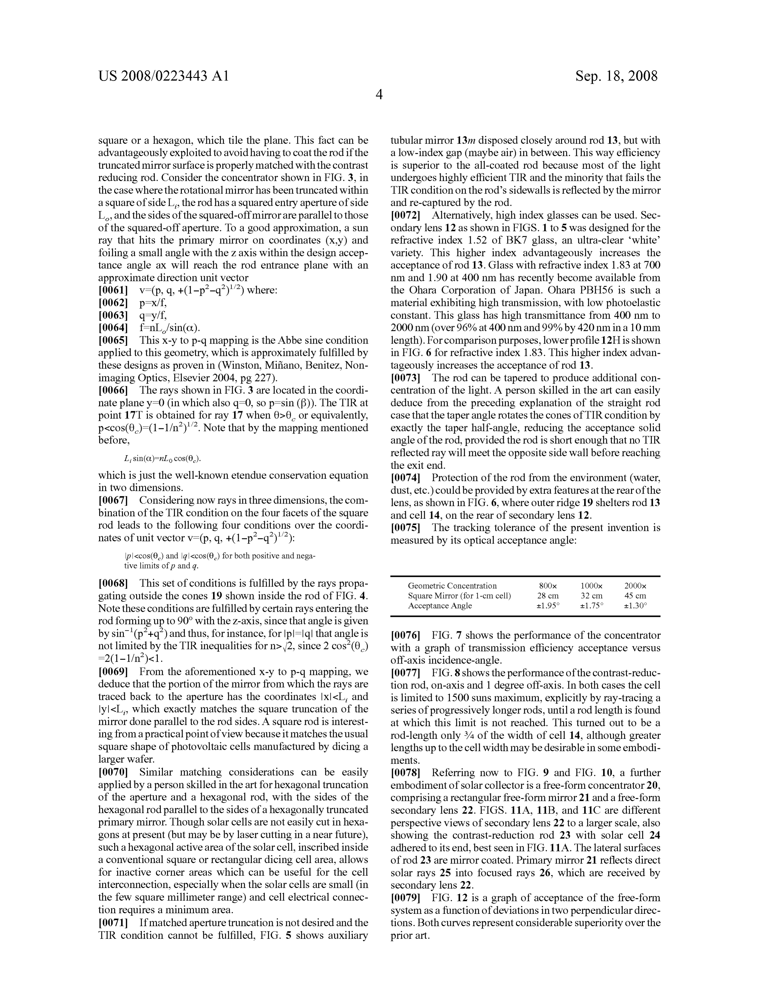
Page 22
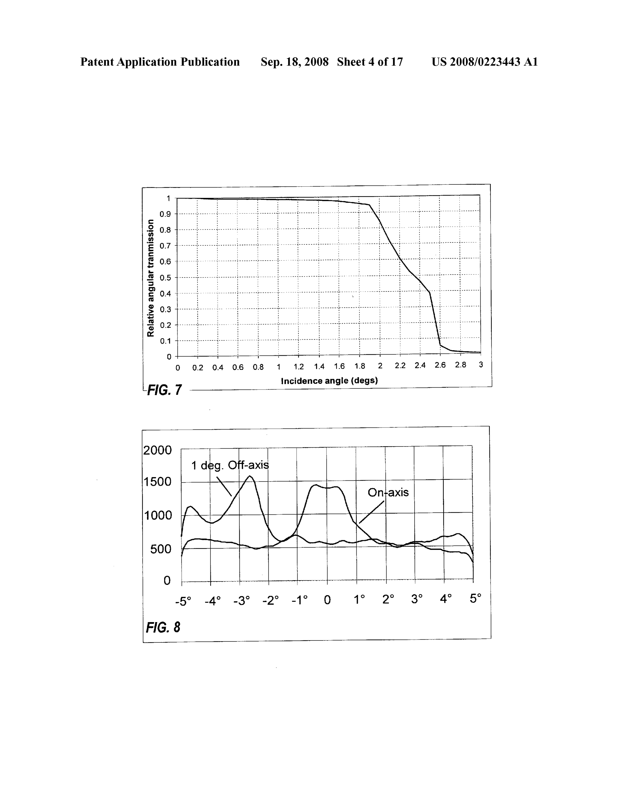
US 2008/0223443 A1 Sep. 18, 2008
square or a hexagon, which tile the plane. This fact can be tubular mirror 13m disposed closely around rod 13, but with advantageously exploited to avoid having to coat the rod if the a low-index gap (maybe air) in between. This way efficiency truncated mirror Surface is properly matched with the contrast is superior to the all-coated rod because most of the light reducing rod. Consider the concentrator shown in FIG. 3, in undergoes highly efficient TIR and the minority that fails the the case where the rotational mirror has been truncated within TIR condition on the rod's sidewalls is reflected by the mirror a square of side L, the rod has a squared entry aperture of side and re-captured by the rod.
L., and the sides of the squared-off mirror are parallel to those 0072 Alternatively, high index glasses can be used. Sec of the squared-off aperture. To a good approximation, a Sun ondary lens 12 as shown in FIGS. 1 to 5 was designed for the ray that hits the primary mirror on coordinates (x,y) and refractive index 1.52 of BK7 glass, an ultra-clear white foiling a small angle with the Z axis within the design accep variety. This higher index advantageously increases the tance angle ax will reach the rod entrance plane with an acceptance of rod 13. Glass with refractive index 1.83 at 700 approximate direction unit vector nm and 1.90 at 400 nm has recently become available from the Ohara Corporation of Japan. Ohara PBH56 is such a 0062 p=X/f, material exhibiting high transmission, with low photoelastic 0063 qy/f, constant. This glass has high transmittance from 400 nm to 0064 f-nL/sin(o). 2000 nm (over 96% at 400 nm and 99% by 420 nm in a 10 mm 0065. This x-y top-q mapping is the Abbe sine condition length). For comparison purposes, lower profile 12His shown applied to this geometry, which is approximately fulfilled by in FIG. 6 for refractive index 1.83. This higher index advan these designs as proven in (Winston, Mifiano, Benitez, Non tageously increases the acceptance of rod 13. imaging Optics, Elsevier 2004, pg. 227). 0073. The rod can be tapered to produce additional con 0066. The rays shown in FIG.3 are located in the coordi centration of the light. A person skilled in the art can easily nate planey=0 (in which also q=0, so p=sin (B)). The TIR at deduce from the preceding explanation of the straight rod point 17T is obtained for ray 17 when 0>0 or equivalently, case that the taper angle rotates the cones of TIR condition by p<cos(0)=(1-1/n)'. Note that by the mapping mentioned exactly the taper half-angle, reducing the acceptance solid before, angle of the rod, provided the rod is short enough that no TIR Li sin(C)=nLo cos(0). reflected ray will meet the opposite side wall before reaching the exit end.
which is just the well-known etendue conservation equation 0074 Protection of the rod from the environment (water, in two dimensions. dust, etc.) could be provided by extra features at the rear of the 0067 Considering now rays in three dimensions, the com lens, as shown in FIG. 6, where outer ridge 19 shelters rod 13 bination of the TIR condition on the four facets of the square and cell 14, on the rear of secondary lens 12. rod leads to the following four conditions over the coordi 0075. The tracking tolerance of the present invention is nates of unit vector v=(p, q, +(1-p-q)'); measured by its optical acceptance angle: |p|<cos(60) and |q|<cos(9) for both positive and mega tive limits of p and q.
0068. This set of conditions is fulfilled by the rays propa Geometric Concentration 800x 1OOOx 2OOOx gating outside the cones 19 shown inside the rod of FIG. 4. Square Mirror (for 1-cm cell)
Acceptance Angle
Note these conditions are fulfilled by certain rays entering the rod forming up to 90° with the Z-axis, since that angle is given by sin' (pº+qº) and thus, for instance, for|pl=|q| that angle is 0076 FIG. 7 shows the performance of the concentrator not limited by the TIR inequalities for n>2, since 2 cos(0) with a graph of transmission efficiency acceptance versus =2(1-1/n)<1. off-axis incidence-angle.
0069. From the aforementioned x-y to p-q mapping, we 0077 FIG. 8 shows the performance of the contrast-reduc deduce that the portion of the mirror from which the rays are tion rod, on-axis and 1 degree off-axis. In both cases the cell traced back to the aperture has the coordinates |X|<L, and is limited to 1500 Suns maximum, explicitly by ray-tracing a |y|<L, which exactly matches the square truncation of the series of progressively longer rods, until a rod length is found mirror done parallel to the rod sides. A square rod is interest at which this limit is not reached. This turned out to be a ing from a practical point of view because it matches the usual rod-length only 3/4 of the width of cell 14, although greater square shape of photovoltaic cells manufactured by dicing a lengths up to the cell width may be desirable in some embodi larger wafer. mentS.
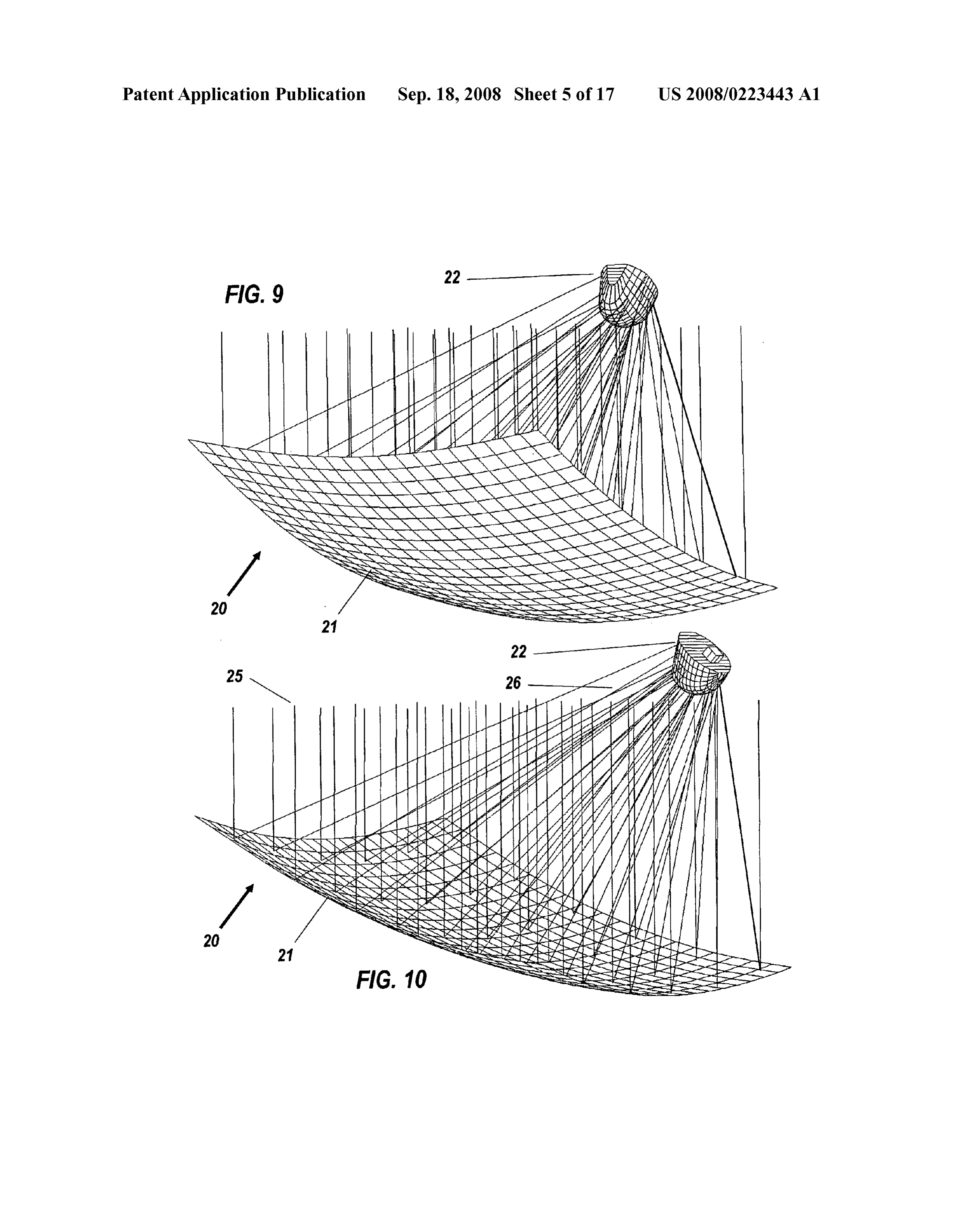
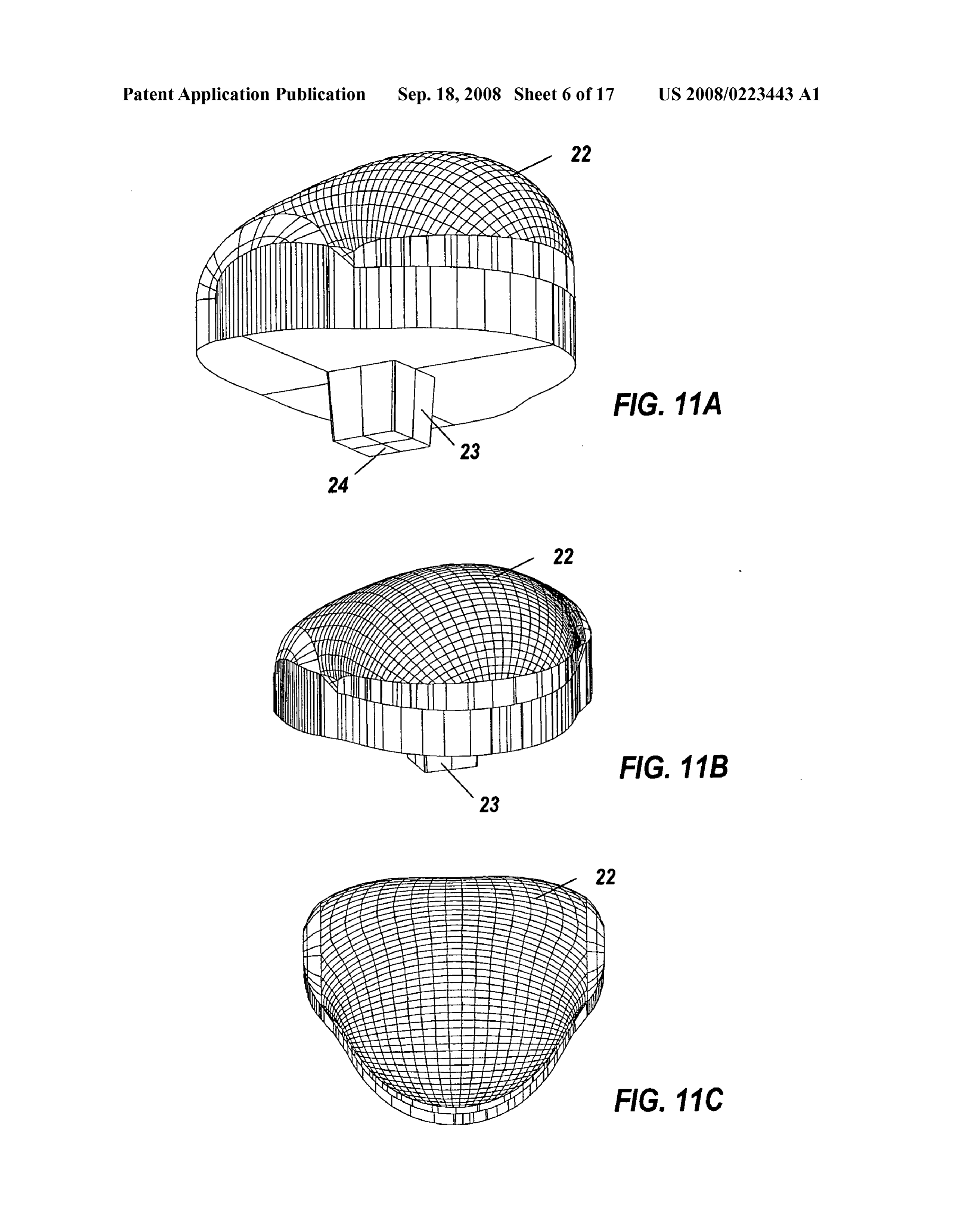
0070 Similar matching considerations can be easily (0078 Referring now to FIG. 9 and FIG. 10, a further applied by a person skilled in the art for hexagonal truncation embodiment of solar collector is a free-form concentrator 20, of the aperture and a hexagonal rod, with the sides of the comprising a rectangular free-form mirror 21 and a free-form hexagonal rod parallel to the sides of a hexagonally truncated secondary lens 22. FIGS. 11A, 11B, and 11C are different primary mirror. Though Solar cells are not easily cut in hexa perspective views of secondary lens 22 to a larger scale, also gons at present (but may be by laser cutting in a near future), showing the contrast-reduction rod 23 with solar cell 24 Such a hexagonal active area of the Solar cell, inscribed inside adhered to its end, best seen in FIG. 11A. The lateral surfaces a conventional square or rectangular dicing cell area, allows of rod 23 are mirror coated. Primary mirror 21 reflects direct for inactive corner areas which can be useful for the cell solar rays 25 into focused rays 26, which are received by interconnection, especially when the Solar cells are Small (in secondary lens 22.
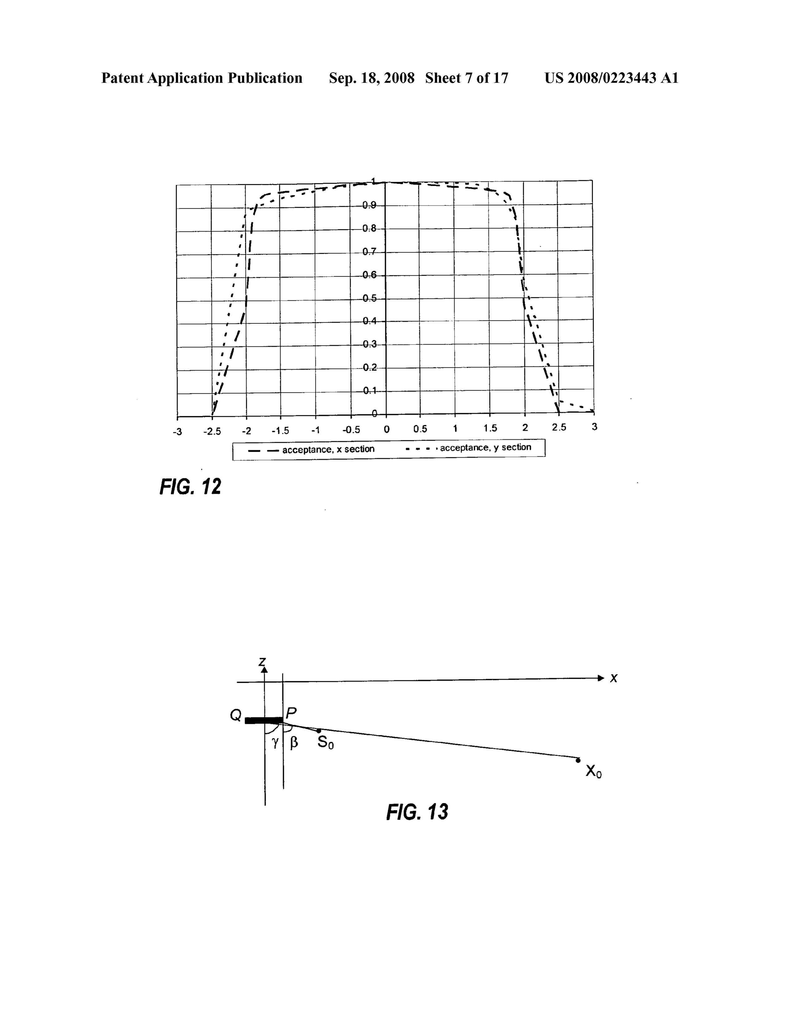
the few square millimeter range) and cell electrical connec 007.9 FIG. 12 is a graph of acceptance of the free-form tion requires a minimum area. system as a function of deviations in two perpendicular direc 0071. If matched aperture truncation is not desired and the tions. Both curves represent considerable superiority over the TIR condition cannot be fulfilled, FIG. 5 shows auxiliary prior art.
Page 23
US 2008/0223443 A1 Sep. 18, 2008
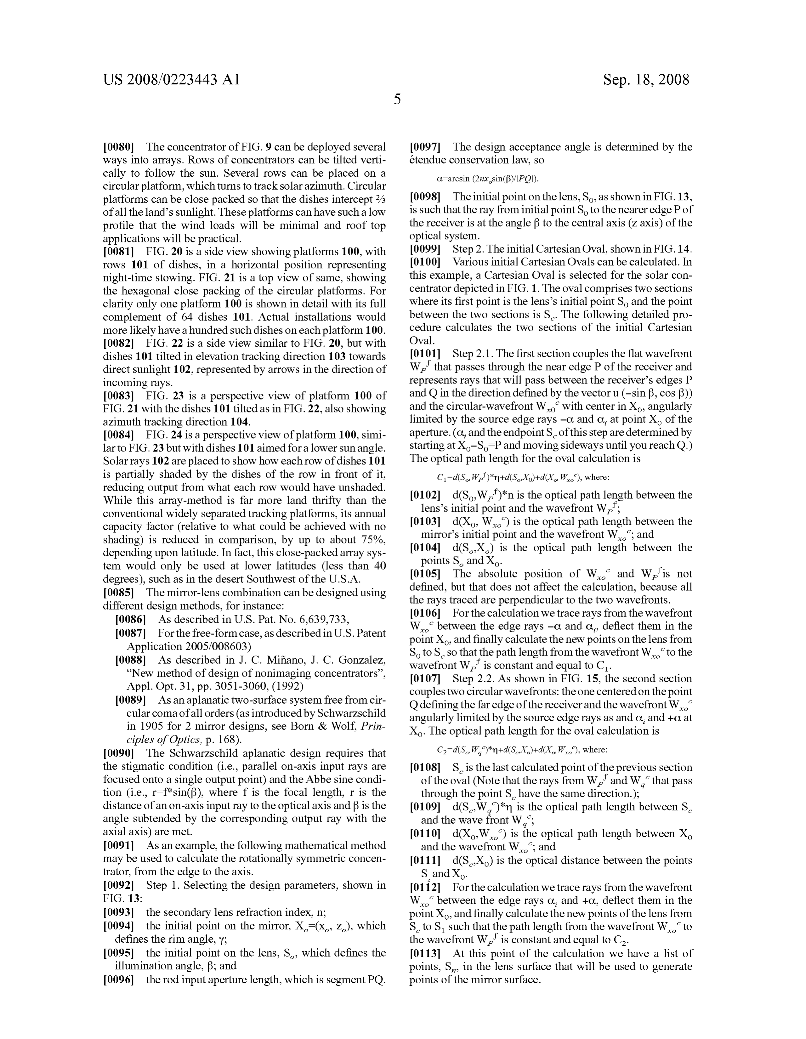
0080. The concentrator of FIG.9 can be deployed several 0097. The design acceptance angle is determined by the ways into arrays. Rows of concentrators can be tilted verti étendue conservation law, so cally to follow the sun. Several rows can be placed on a C-arcsin (2nxsin(f)/IPO).
circular platform, which turns to track solar azimuth. Circular platforms can be close packed so that the dishes intercept 2/3 0098. The initial point on the lens. So, as shown in FIG. 13, of all the land's sunlight. These platforms can have such a low is such that the ray from initial point So to the nearer edge P of profile that the wind loads will be minimal and roof top the receiver is at the angle? to the central axis (Z axis) of the applications will be practical. optical system.
I0081 FIG. 20 is a side view showing platforms 100, with (0099 Step 2. The initial Cartesian Oval, shown in FIG. 14. rows 101 of dishes, in a horizontal position representing 0.100 Various initial Cartesian Ovals can be calculated. In night-time stowing. FIG. 21 is a top view of same, showing this example, a Cartesian Oval is selected for the solar con the hexagonal close packing of the circular platforms. For centrator depicted in FIG.1. The oval comprises two sections clarity only one platform 100 is shown in detail with its full where its first point is the lens's initial point So and the point complement of 64 dishes 101. Actual installations would between the two sections is S. The following detailed pro more likely have a hundred such dishes on each platform 100. cedure calculates the two sections of the initial Cartesian 0082 FIG. 22 is a side view similar to FIG. 20, but with Oval.
dishes 101 tilted in elevation tracking direction 103 towards 0101 Step 2.1. The first section couples the flat wavefront direct sunlight 102, represented by arrows in the direction of W, that passes through the near edge P of the receiver and incoming rays. represents rays that will pass between the receiver's edges P I0083 FIG. 23 is a perspective view of platform 100 of and Q in the direction defined by the vector u (-sin B, cos B)) FIG. 21 with the dishes 101 tilted as in FIG.22, also showing and the circular-wavefront Wo with center in Xo, angularly azimuth tracking direction 104. limited by the source edge rays -O. and C, at point X of the 0084 FIG. 24 is a perspective view of platform 100, simi aperture. (C, and the endpoint S of this step are determined by lar to FIG.23 but with dishes 101 aimed for a lower sun angle. starting at Xo-SP and moving sideways until you reach Q.) Solar rays 102 are placed to show how each row of dishes 101 The optical path length for the oval calculation is is partially shaded by the dishes of the row in front of it, reducing output from what each row would have unshaded. I0102) d(S.W.)*n is the optical path length between the While this array-method is far more land thrifty than the conventional widely separated tracking platforms, its annual lens's initial point and the wavefront W,': capacity factor (relative to what could be achieved with no (0103 d(X, W) is the optical path length between the shading) is reduced in comparison, by up to about 75%, mirror's initial point and the wavefront W.; and depending upon latitude. In fact, this close-packed array sys 0104 d(SX) is the optical path length between the tem would only be used at lower latitudes (less than 40 points S and X.
degrees), such as in the desert Southwest of the U.S.A. I0105. The absolute position of W. and Wis not 0085. The mirror-lens combination can be designed using defined, but that does not affect the calculation, because all different design methods, for instance: the rays traced are perpendicular to the two wavefronts. 0086. As described in U.S. Pat. No. 6,639,733, 0106 For the calculation we trace rays from the wavefront 0087. For the free-form case, as described in U.S. Patent W between the edge rays -C. and C, deflect them in the Application 2005/008603) point Xo, and finally calculate the new points on the lens from 0088. As described in J. C. Mifano, J. C. Gonzalez, So to S. so that the path length from the wavefront W to the “New method of design of nonimaging concentrators'. wavefront W, is constant and equal to C. Appl. Opt. 31, pp. 3051-3060, (1992) 0107 Step 2.2. As shown in FIG. 15, the second section couples two circular wavefronts: the one centered on the point
I0089. As an aplanatic two-surface system free from cir Q defining the far edge of the receiver and the wavefront W. cular coma of all orders (as introduced by Schwarzschild angularly limited by the source edge rays as and C, and +C. at in 1905 for 2 mirror designs, see Born & Wolf, Prin Xo. The optical path length for the oval calculation is ciples of Optics, p. 168).
0090 The Schwarzschild aplanatic design requires that C=d(S.W.)*n+d(SX)+d(XW), where: the Stigmatic condition (i.e., parallel on-axis input rays are I0108) S is the last calculated point of the previous section focused onto a single output point) and the Abbe sine condi of the oval (Note that the rays from W, and W, that pass tion (i.e., r—f sin(B), where f is the focal length, r is the through the point S have the same direction.); distance of an on-axis input ray to the optical axis and B is the (0109) d(S.W.)*m is the optical path length between S. angle Subtended by the corresponding output ray with the and the wave front W:
axial axis) are met. I0110 d(XW) is the optical path length between X 0091. As an example, the following mathematical method and the wavefront W.; and may be used to calculate the rotationally symmetric concen I0111 d(SX) is the optical distance between the points trator, from the edge to the axis. S. andXo.
0092 Step 1. Selecting the design parameters, shown in 0112 For the calculation we trace rays from the wavefront FIG. 13: W between the edge rays C, and +C, deflect them in the 0093 the secondary lens refraction index, n; point Xo, and finally calculate the new points of the lens from 0094 the initial point on the mirror, X(x, Z), which S. to S such that the path length from the wavefront W, to defines the rim angle, Y: the wavefront W, is constant and equal to C. 0095 the initial point on the lens, S, which defines the 0113. At this point of the calculation we have a list of illumination angle, B; and points, S. in the lens Surface that will be used to generate 0096 the rod input aperture length, which is segment PQ. points of the mirror surface.
Page 24
US 2008/0223443 A1 Sep. 18, 2008
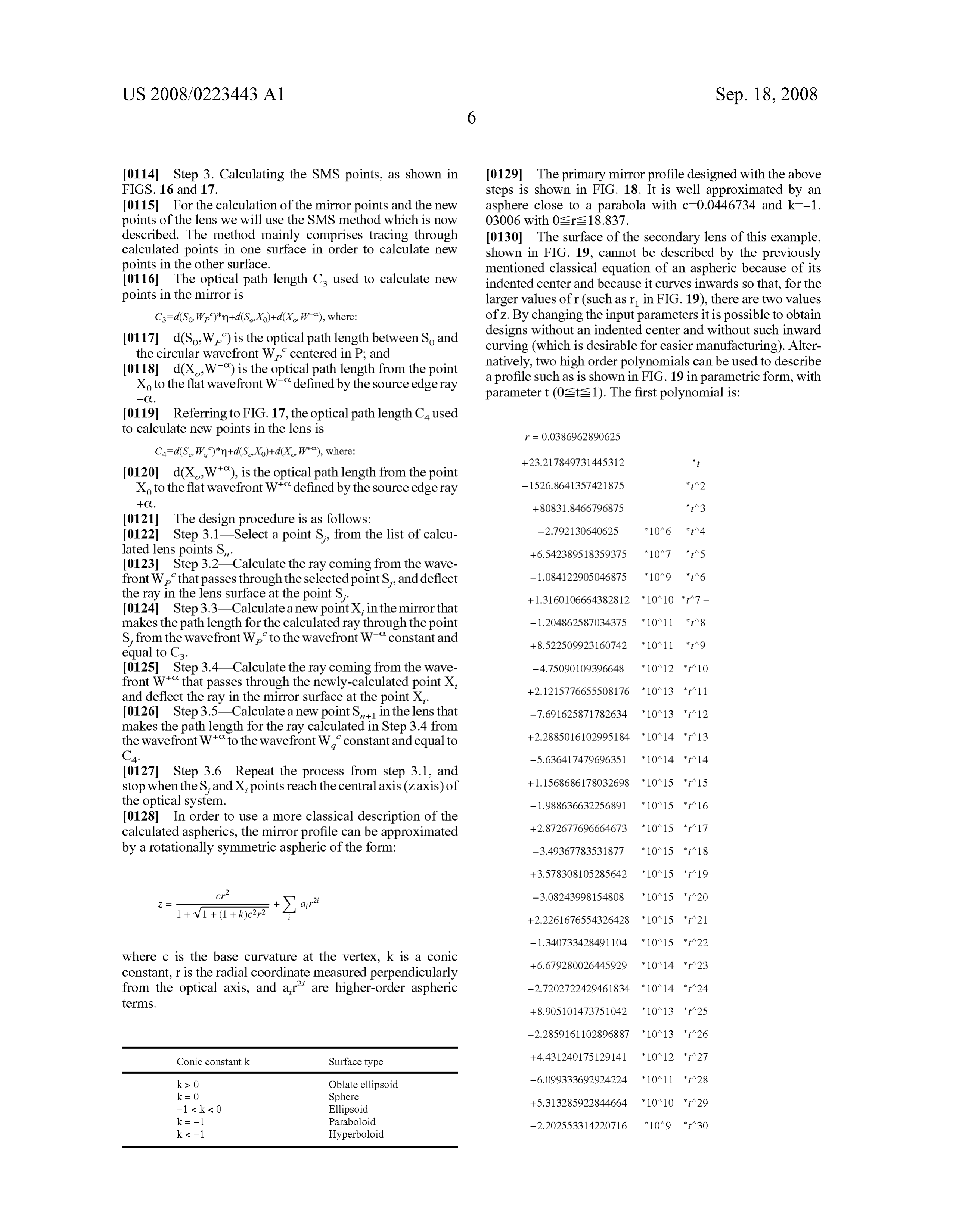
0114 Step 3. Calculating the SMS points, as shown in I0129. The primary mirror profile designed with the above FIGS. 16 and 17. steps is shown in FIG. 18. It is well approximated by an 0115 For the calculation of the mirror points and the new asphere close to a parabola with c=0.0446734 and k=-1. points of the lens we will use the SMS method which is now 03006 with Osrs 18.837.
described. The method mainly comprises tracing through 0.130. The surface of the secondary lens of this example, calculated points in one surface in order to calculate new shown in FIG. 19, cannot be described by the previously points in the other Surface. mentioned classical equation of an aspheric because of its 0116. The optical path length Cs used to calculate new indented center and because it curves inwards so that, for the points in the mirror is larger values of r(such as r in FIG. 19), there are two values C=d(So, W)*m+d(SX)+d(XW), where: of Z. By changing the input parameters it is possible to obtain 0117 d(S.W.) is the optical path length between S and designs without an indented center and without Such inward the circular wavefront W, centered in P; and curving (which is desirable for easier manufacturing). Alter 0118 d(XW) is the optical path length from the point natively, two high order polynomials can be used to describe X to the flat wavefront W defined by the source edge ray a profile such as is shown in FIG. 19 in parametric form, with -O. parameter t (Osts 1). The first polynomial is: 0119 Referring to FIG. 17, the optical path length Caused to calculate new points in the lens is r = 0.0386962890625
Ca=d(S.W.)*n+d(SXo)+d(X W"), where: +23.217849731445312 * 0120 d(XW), is the optical path length from the point
X to the flat wavefront W“defined by the source edge ray - 1526.864135742.1875 *t^2 --O. +8O831.8466796875 ** 3 0121 The design procedure is as follows:
I0122) Step 3.1—Select a point S, from the list of calcu lated lens points S. +6.542389518359375 *10^7 *f^5 0123 Step 3.2 Calculate the ray coming from the wave front W, that passes through the selected point S, and deflect ?1.084122905046875 *10^9 *f^6 the ray in the lens surface at the point S, + 1.316()106664382812 * 1 ()^1 () *i^7} — 0.124 Step 3.3—Calculate a new point X, in the mirror that makes the path length for the calculated ray through the point -1.204862587.034375 10^11 f^8 S, from the wavefront W, to the wavefront W“constant and equal to Cs. + 8.522509923160742 * 10^11 * t^9 0.125 Step 3.4 Calculate the ray coming from the wave ?4.75090109396648 *10^12 *f^10 front W' that passes through the newly-calculated point X, 2.1215776655508176 10^13 f^11 and deflect the ray in the mirror surface at the point X.
0126 Step 3.5—Calculate a new point S in the lens that - 7.691625871782634 10^13 * i 12 makes the path length for the ray calculated in Step 3.4 from + 2.28850 16102995184 · 10^14 : 13 the wavefront W“to the wavefront W, constant and equal to
C4. -5.63641 {4{9696351 * 1 ()^14 *??^14 0127 Step 3.6—Repeat the process from step 3.1, and
stop when the S, and X, points reach the centralaxis (Zaxis) of the optical system. - 1988636632 256891 * 10^15 * i 16 0128. In order to use a more classical description of the calculated aspherics, the mirror profile can be approximated +-2.87267 7696664673 10^15 * i 17 by a rotationally symmetric aspheric of the form: -3.49367783531877 * 10^15 f^18
where c is the base curvature at the vertex, k is a conic --6.6 ||928()()26445929 * 1 ()^14 *??^23 constant, r is the radial coordinate measured perpendicularly from the optical axis, and air are higher-order aspheric -2.72027224294.61834 10^14 it 24 terms.
Conic constantk Surface type +443124O175129141 10^12 ti
ki> 0 Oblate ellipsoid —6.099333692924224 * 10^11 * t^28
-1 < k < 0 Ellipsoid +5.313285922844664 * 10^1 () * t^29 k = -1 Paraboloid -2.202553314220716 10^9 f^30
Page 25
US 2008/0223443 A1 Sep. 18, 2008
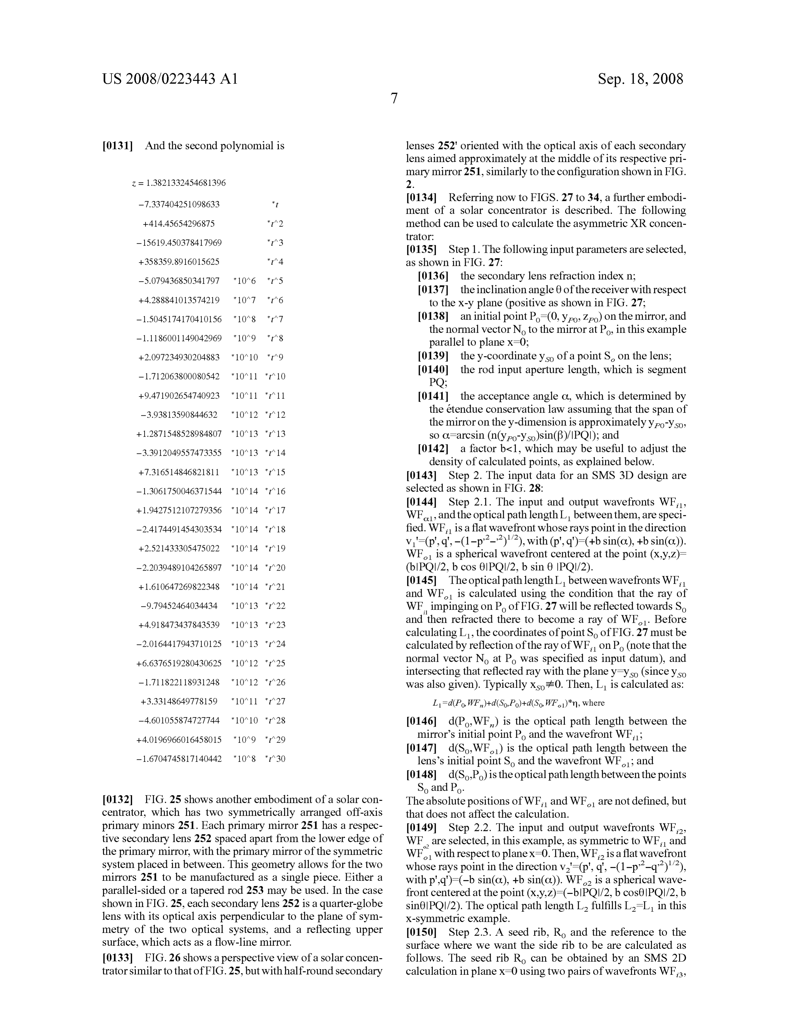
0131 And the second polynomial is lenses 252 oriented with the optical axis of each secondary lens aimed approximately at the middle of its respective pri mary mirror 251, similarly to the configuration shown in FIG.
-7.337404251098633 * I0134) Referring now to FIGS. 27 to 34, a further embodi ment of a solar concentrator is described. The following ?41445654296875 *t^2 method can be used to calculate the asymmetric XR concen tratOr:
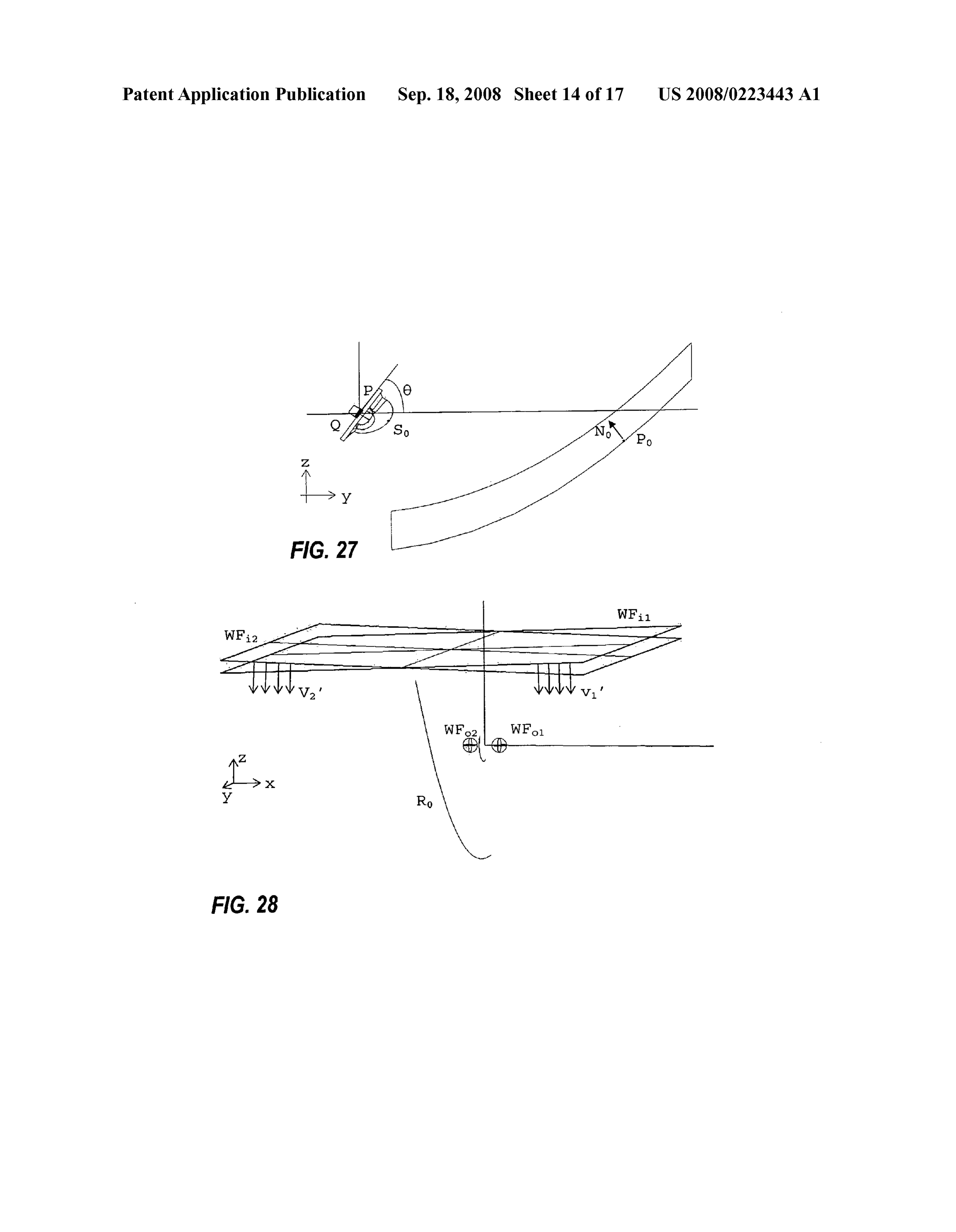
0.135 Step 1. The following input parameters are selected, 358359.8916O15625 * ??^4 as shown in FIG. 27:
-5.079436850341797 * 10/? 6 * ? ?.5 0.136 the secondary lens refraction index n: 0.137 the inclination angle 0 of the receiver with respect +4.288841013574219 *10^7 *f^6 to the x-y plane (positive as shown in FIG. 27: - 1504,5174170410156 10^8 f7 0.138 an initial point Po (0, y, z) on the mirror, and
the normal vector No to the mirror at Po, in this example parallel to plane x=0;
--2.097234930204883 * 10/10 * ? ?? 9 0.139 the y-coordinateys of a point S on the lens;
0140 the rod input aperture length, which is segment
9.47 1902654740923 10^11 it 11 0.141 the acceptance angle C, which is determined by --3.93813590844632 10^1 2 | 12 the étendue conservation law assuming that the span of the mirror on the y-dimension is approximately yo-yso, +1.2871548528984807 *10^13 *f^13 so C=arcsin (n(yeol-yso)sin(B)/IPQI); and -3.391204.9557473355 * 10^13 it 14 0.142 a factor b-1, which may be useful to adjust the density of calculated points, as explained below.
0.143 Step 2. The input data for an SMS 3D design are - 1.306175004.6371544 10^14 it 16 selected as shown in FIG. 28:
0144 Step 2.1. The input and output wavefronts WF,
WF, and the optical path length L betweenthem, are speci -2.4174.4914.54303534 10^14 it 18 fied. WF, is a flat wavefront whose rays point in the direction
v'=(p', q', -(1-p^*-*)"*), with (p', q')=(+b sin(C), +b sin(C)).
WF is a spherical wavefront centered at the point (x,y,z)= ?2.2039489104265897 *10^14 *f^20 (b|PQI/2, b cos 60||PQI/2, b sin 0 ||PQI/2). + 1.61064T269822348 * 10^14 t'^21 (0145 The optical path length L between wavefronts WF, and WF is calculated using the condition that the ray of -9.794524.64034434 10^13 it WF impinging on P of FIG. 27 will be reflected towards So --4.91 8473,437843539 * 1 ()^13 * ??^23 and then refracted there to become a ray of WF. Before calculating L, the coordinates of point So of FIG.27 must be —2.016441794371 01:25 * 10^13 * t^24 calculated by reflection of the ray of WF, on Po (note that the 6.637651928.0430625 10^12 it 25 normal vector No at Po was specified as input datum), and intersecting that reflected ray with the planey-ys (sinceys -1.7118221 1893.1248 10^12 f26 was also given). Typically Xso,70. Then, L is calculated as:
-4.601055874727744 * 10^10 f^28 I0146) d(PWF) is the optical path length between the +4.0196966016458015 *10^9 *f^29 mirror's initial point Po and the wavefront WF; 0147 d(SWF) is the optical path length between the -16704745817.140442 10^8 t3O lens's initial point So and the wavefront WF; and 0148 d(SP) is the optical path length between the points
So, and Po.
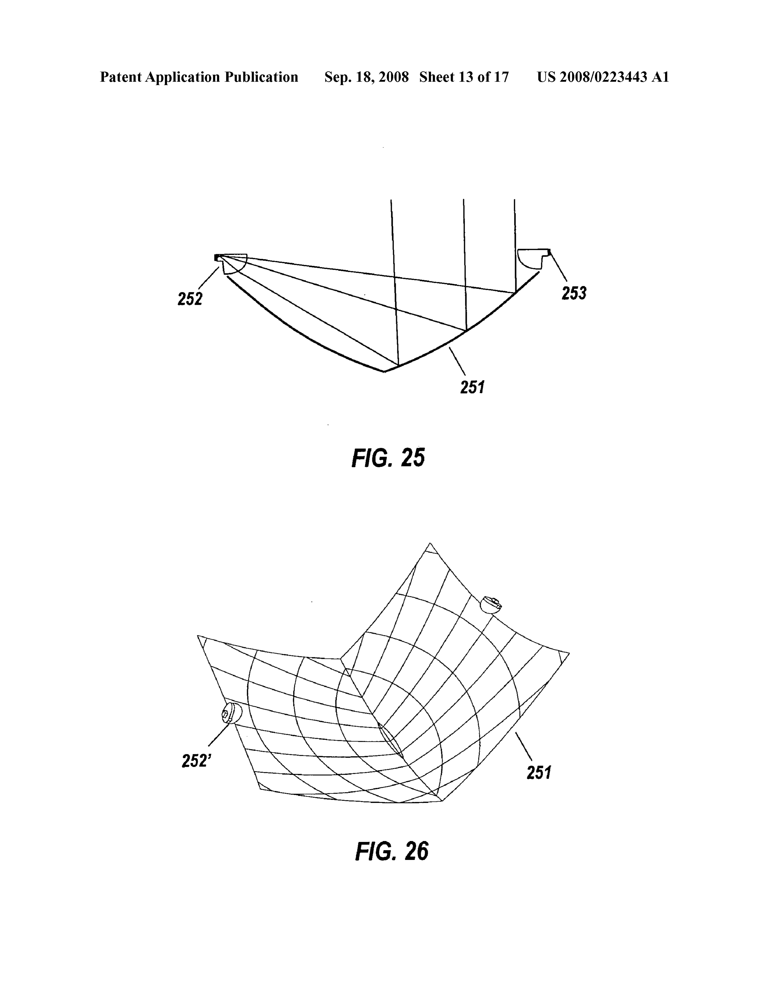
(0132 FIG. 25 shows another embodiment ofa solar con The absolute positions of WF, and WF are not defined, but centrator, which has two symmetrically arranged off-axis that does not affect the calculation. primary minors 251. Each primary mirror 251 has a respec I0149 Step 2.2. The input and output wavefronts WF, tive secondary lens 252 spaced apart from the lower edge of WF are selected, in this example, as symmetric to WF, and the primary mirror, with the primary mirror of the symmetric WF with respect to planex=0. Then, WF is a flat wavefront system placed in between. This geometry allows for the two whose rays point in the direction v.'-(p', q', -(1-p-q)'), mirrors 251 to be manufactured as a single piece. Either a with p".d')=(-b sin(C.), +b sin(o)). WF is a spherical wave parallel-sided or a tapered rod 253 may be used. In the case front centered at the point (x,y,z)=(-b|PQI/2, b cos0PQ)/2, b shown in FIG. 25, each secondary lens 252 is a quarter-globe sin6IPOI/2). The optical path length L fulfills L-L in this lens with its optical axis perpendicular to the plane of sym X-symmetric example.
metry of the two optical systems, and a reflecting upper (O150 Step 2.3. A seed rib, Ro and the reference to the Surface, which acts as a flow-line mirror. surface where we want the side rib to be are calculated as 0.133 FIG. 26 shows a perspective view of a solar concen follows. The seed rib Ro can be obtained by an SMS 2D trator similar to that of FIG.25, but with half-round secondary calculation in plane x=0 using two pairs of wavefronts WF,
Page 26
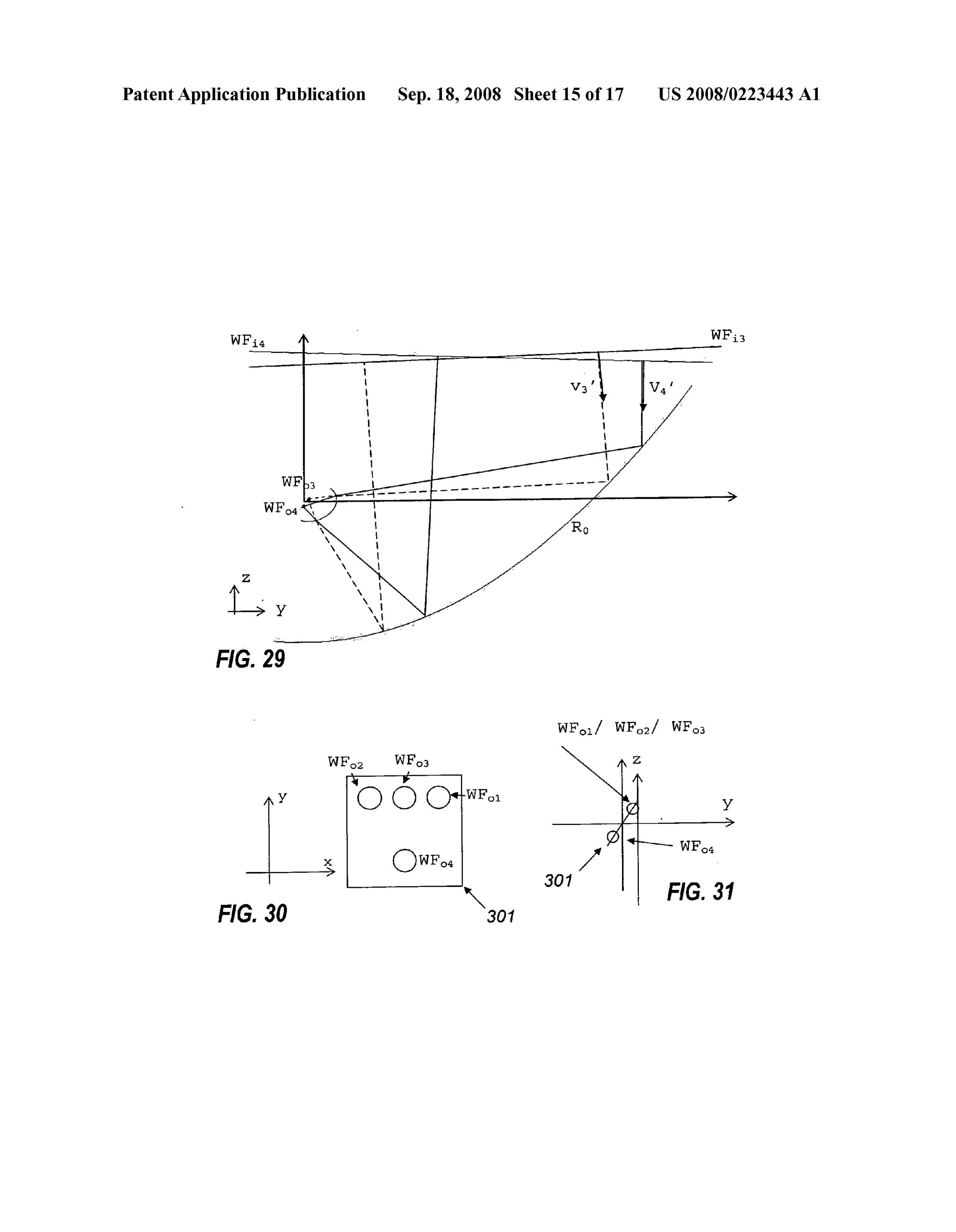
US 2008/0223443 A1 Sep. 18, 2008
WF and WF, WF as shown in FIG. 29. WF, is a flat tesian oval Surface when a one-parameter set of rays of one of wavefront whose rays point in the direction v'(p', q', -(1- the wavefronts is known (the one-parameter set of rays is p-q)'), with (p'.q)=(0.+b sin(o)) and it couples WFs formed by the rays of WF, after reflection at the curve Ro). which is a spherical wavefront centered at the point (x,y,z)= (0160 Subsequent steps will produce curves R belonging (0, b cos0 |PQI/2, b sin6 |PQI/2). WF, is a flat wavefront to the mirror Surface and curves R belonging to the lens whose rays point in the direction V-(p', q', -(1-p-q)'), Surface, as well as the normals to the Surfaces along those with (p'q)=(0.-b sin(o)) and it couples WF, which is curves. The curves together with their surface normals will be spherical wavefront centered at the point (x,y,z)=(0.-b called SMS ribs henceforth. The SMS ribs are shown in FIG. cos0|PQ)/2, -b sin0 POI/2). For simplicity, a singleb param 33, and run alongside each other and transverse to the ribs eter is used everywhere. The optical path lengths L between shown in FIG. 34.
wavefronts WF, and WF can be selected equal to Land L. 0.161 The surfaces of the mirror and lens are calculated as An optical path length La between wavefronts WF, and WF an interpolating surface of the SMS ribs (consistent with the is chosen (and its value will be adjusted next). normal vector). Such an interpolation can be easily done, for 0151 FIGS. 30 and 31 show the relative positions of the instance, using a loft Surface interpolation available in most four out wavefronts WF, WF, WF, WF, relative to the CAD packages.
input end of the rod 301. FIG. 30 is a view along the Z axis, (0162 Assume that the equation of the seed rib curve R is FIG. 31 is a view along the x axis. given in parametric formas P=Ro(u). A natural parameteriza 0152 Step 3. Referring to FIG. 32, the initial curve, i.e., tion P-R,(u) is induced in the other rib curves generated by the seed rib Ro, is designed: the SMS method. With this parameterization, points corre 0153 Step 3.1. Trace the ray of the wavefront WF, pass sponding to the same u value are points that belong to the ing through initial point P of the mirror surface X. Since the same SMS chain, i.e., each value of u defines an SMS chain. normal No is known, we can compute the reflection of that ray 0163 The parameterb-1 set at the beginning can be used at Po. to select the number of points along the seed rib and the 0154 Step 3.2. Calculate the point S along that ray tra number of ribs to be designed (the smaller b, the higher the jectory after refraction at Po Such that the optical path length number of points and ribs).
from the wavefront WF, to the wavefront WF is L. 0164. Although specific embodiments have been 0155 Step 3.3. Once S has been calculated, since the ray described, the skilled reader will understand how features of trajectory Po after and before the refraction at S is known, we different embodiments may be combined and substituted, and can calculate the normal vector N to the surface Rat point P. such combinations are within the scope of the present inven by inverting the Snell law. tion.
0156 Step 3.4. Once S and N have been calculated the 0.165 For example, as discussed above, the embodiments procedure is repeated Starting at S and tracing backward the shown in the drawings are primarily based on designing the ray from WF passing through S. With a similar procedure secondary lens 12 for glass with a refractive index of 1.52 to that described above, the point P of the surface X is Alternatively, a different material. Such as glass with a refrac calculated using Las optical path length from the wavefront tive index of 1.83, may be used. The very high refractive index WF to the wavefront WF. After that, the normal N to the improves the TIR acceptance angle of the rod, as well as surface X at the P. point can be calculated. Interpolate a allowing a lower profile for the lens. The high index also low-order curve between P and P. compatible with No and opens the possibility of improving the optics by, for example, N, (i.e., a curve perpendicular to normal vectors No and N: minimal or at least Substantially reduced truncation of a cir for instance, a Hermite interpolating polynomial). Iterate cular aperture of a rotationally symmetric design. over the value of La (i.e. go back to Step 2.3) to make this 0166 However, there are possible offsetting disadvan interpolating curve as Smooth as possible. tages. First, in practical embodiments the rod exit is typically 0157. The calculation of points can be repeated to get a glued to the actual photovoltaic cell with a transparent, stable sequence of points (and normal vectors), called SMS elastomeric material, which will then be of lower refractive sequence, of both surfaces in the X=0 plane. Global interpo index. The reliable glues presently available for this applica lating curves are computed (separately for each surface) and tion are silicones with n-1.54. Because of the low-index glue the one corresponding to the sequence of points on the mirror layer, the lens to cell interface will have higher Fresnel reflec is called seed rib R. R will be the input data for the further tion losses unless a Sophisticated anti-reflection coating is SMS 3D surface generation process. applied at the rod exit. Second, if the difference in refractive 0158 Step 4. The resulting optical system will couple the index between the rod and the elastomeric glue is large rays of the wavefronts WF, with WF, and WF, with WF enough, the TIR critical angle at that interface may become and will consist of two surfaces R and X, where X contains the limiting angle for the acceptance of the rod, i.e. a new curve Ro. This surface calculation is described next and illus restrictive cone appears. Third, the Fresnel reflection at the trated in FIGS. 33 and 34. active lens surface is also higher, and if that Surface has an 0159. The normal vectors to the mirror on points of the anti-reflective coating more layers are needed to lower the curve Ro are also selected. Such a selection must be consistent reflectivity. The skilled person understands how to select an with the constraint that these normal vectors are perpendicu appropriate compromise among these competing consider lar to the curve R. Assume that an SMS chain can be gener ations in a specific case.
ated from any point M of the curve Rousing the described 0.167 Although the described embodiments have mirror procedure, but now for wavefronts WF, with WF, and WF and lens Surfaces shaped to concentrate the incident light in with WF. The set of points generated from all the points of two dimensions, the skilled reader will understand how to Ro, at the first step of the SMS chain generation, form another apply the present teachings to construct a mirror and lens curve R on the lens. Note that the calculation of the curve R Surface shaped to concentrate the incident light in one dimen is the calculation of a curve contained in a generalized Car sion along the length of a trough-like concentrator. Such
Page 27
US 2008/0223443 A1 Sep. 18, 2008
concentrators are easier to operate; if the concentrator is 5. A concentrator according to claim 4, wherein said rod aligned equatorially, the only tracking required is adjustment has a cross section Substantially identical to a shape of a of elevation according to the time of year. However, trough light-receiving area of said photovoltaic cell. concentrators do not easily provide the very high concentra 6. A concentrator according to claim 1, wherein said rod tion factors that can be achieved by concentrating in two has a length less than twice the minimum width of the rod at dimensions.
an entry end of the rod.
(0.168 Although the described embodiments are solar con 7. A concentrator according to claim 1, wherein said pri centrators for photovoltaic Solar power generation, the optics mary mirror and said front Surface of said secondary lens of the present application may be used for other purposes. In form an essentially aplanatic system with focal plane essen addition, the embodiments presented here may be used for the tially at the entry of the rod Such that any axial ray entering the reverse application as an emitting device by replacing the system, when traced through the system, reaches an entry photovoltaic cell by a source Such as one or a cluster of light plane of the rod at a point offset by less than 0.25 times the emitting diode (LED) sources. Such a device is especially minimum rod entry width from the point at which the corre applicable to thin-film high flux LEDs and packages, which sponding ray in an exactly aplanatic system would reach the can be obtained in a form that is well adjusted to be coupled entry plane of the rod.
to the rod. This rod would act as a homogenizer that makes luminance variation on the LED plane invisible, or at least 8. A concentrator according to claim 1, wherein said pri less noticeable, in the output radiation, by doing so allows for mary mirror Surface is a portion of a rotationally symmetric tolerance in LED positioning without affecting the exit inten Surface.
sity pattern, and can even act as a color mixerif different color 9. A concentrator according to claim 1, wherein at least a LEDs are used. The coupling of the LEDs and the rod could central portion of the front Surface of said secondary lens can be done with an airgap. So that collimation at this end of the be substantially represented by a polynomial Z=f(r) with a rod will occur, or with an index matching gel or adhesive. In non-null first order term representing a discontinuity of the this last case, if no mirror coating is to be applied, the use of first derivative of Z at the origin. a high refractive index rod (eitherglass or plastic) is preferred 10. A concentrator according to claim 1, wherein for light for maximizing the LED light collection by TIR. The choice incident parallel to a principal axis of the primary minor and of coupling may depend on the angular distribution of the reaching the distal end of the rod, the maximum angle of emission from the LEDs. deflection at the primary mirror is at least 90°. (0169. Although glass lenses and rods have been described, 11. A concentrator according to claim 1, wherein ignoring other materials may be used. For example, in Some emitter losses the proportion of incident collimated light power applications the lens and rod could be made by plastic injec reaching the distal end of the rod is at least 70% for directions tion using a plastic material the UV stability of which would of incidence within 1° of a primary axis. not be satisfactory in a Solar concentrator. 12. A concentrator according to claim 1, wherein for inci 0170 The preceding description of the presently contem dent light having the geometrical properties of direct Sunlight plated best mode of practicing the invention is not to be taken the proportion of incident light power reaching the distal end in a limiting sense, but is made merely for the purpose of of the rod is at least 90% of a maximum value for directions describing the general principles of the invention. The full of incidence within 1.8° of a primary axis. scope of the invention should be determined with reference to 13. A concentrator according to claim 1, wherein for light the Claims.
incident parallel to a primary axis the maximum intensity of light at the distal end of the rod does not exceed four times the
We claim: average intensity of light at the distal end of the rod. 1. An optical concentrator comprising: 14. A concentrator according to claim 1, wherein the rod is a concave primary mirror arranged to reflect collimated a solid rod of dielectric material and is totally internally incident light to a primary focal region; reflecting for direct Sunlight incident on the primary mirror a secondary refracting lens disposed at the primary focal with the Sun centered on a primary axis. region of said primary mirror, said secondary lens com 15. A concentrator according to claim 1, wherein for direct prising a rear Surface having a light-conducting rod pro solar illumination of the primary mirror with the Sun centered truding from said rear Surface and a front Surface to on a principal axis the average light intensity on the trans receive said reflected light and refract said light towards ducer is at least 200 times the intensity of the incident illumi said rod; nation.
said rod having a reflective lateral Surface and a distal end; 16. A photovoltaic concentrator according to claim 1, fur and ther comprising a second primary mirror arranged symmetri an optical transducer optically adhered to said distal end of cally with the first said primary mirror, a second secondary said rod to receive said refracted light from said second refracting lens symmetrical with the first secondary lens dis ary lens through said rod. posed at the primary focal region of the second primary 2. A concentrator according to claim 1, which is at least one mirror, and a second rod and transducer positioned to receive of a photovoltaic concentrator wherein the optical transducer the refracted light from the second secondary lens, wherein is a photovoltaic cell and a collimating emitter wherein the the first secondary lens is positioned at an outer edge of the optical transducer is a light Source. second primary mirror and the second secondary lens is posi 3. A photovoltaic concentrator according to claim 2 that is tioned at an outer edge of the first primary mirror. Suitable for use as a Solar power generator. 17. A photovoltaic collector comprising one or more plat 4. A concentrator according to claim 1, wherein said rod forms rotatable in azimuth carrying a plurality of devices has a uniform cross section along its length. rotatable in altitude, each said device comprising a row of
Page 28
US 2008/0223443 A1 Sep. 18, 2008
concentrators according to claim 2 arrayed along an altitude path length between wavefronts at apertures defined by axis, and said plurality of devices arranged with the rows of the mirror and the target, the wavefronts being selected concentrators side by side. from flat wavefronts entering the apertures and circular 18. A method of designing a photovoltaic concentrator, wavefronts centered on edges of the apertures; and comprising: designing a light-conducting rod extending from the target defining an initial point for a concave primary mirror to area towards the external Source, the rod having a length collect and reflect collimated incident light from an no greater than twice its minimum width at the target external source: area, and being of constant width or narrowing towards the external source.
defining an initial point for a secondary lens to collect light 19. A method of manufacturing a concentrator, compris reflected by the primary mirror; ing:
defining a target area on a side of the secondary lens designing a concentrator by the method of claim 18; and towards the external Source; constructing a concentrator in accordance with the design. constructing the shape of the mirror by tracing rays through 20. A method of manufacturing a photovoltaic concentra parts of the lens already constructed, and constructing tor according to claim 19, further comprising providing a the shape of the lens by tracing rays through parts of the photovoltaic cell to receive light from the target area. mirror already constructed between the target and the
Source in Such a manner as to maintain constant optical
Provenance
- Collection
- Patents citing this work
- Original assignee
- Light Prescriptions Innovators LLC
- Pages
- 28
- Method
- pdftotext (the PDF's own text layer) + pdftoppm 300dpi page scans
- Patent office record
- patents.google.com →
- Source
- Google Patents citing-documents table
- Inventors
- Pablo Benitez; Juan Carlos Minano; Maikel Hernandez; Aleksandra Cvetkovic; William A. Parkyn; Light Prescriptions Innovators LLC
- Published
- 2008-09-18
- Transcribed from
- patentimages.storage.googleapis.com →