patent · US4373573
Long term storage and use of solar energy
15 February 1983
Page 1 — bibliographic record
United States Patent (19) 11) 4,373,573 Madwed 45) Feb. 15, 1983 (54) LONG TERM STORAGE AND USE OF Primary Examiner-Samuel Scott SOLAR ENERGY Assistant Examiner-Margaret A. Focarino. (76) Inventor: Albert Madwed, 25 Saxton Dr., Attorney, Agent, or Firm-Hubbell, Cohen, Stiefel & Gross
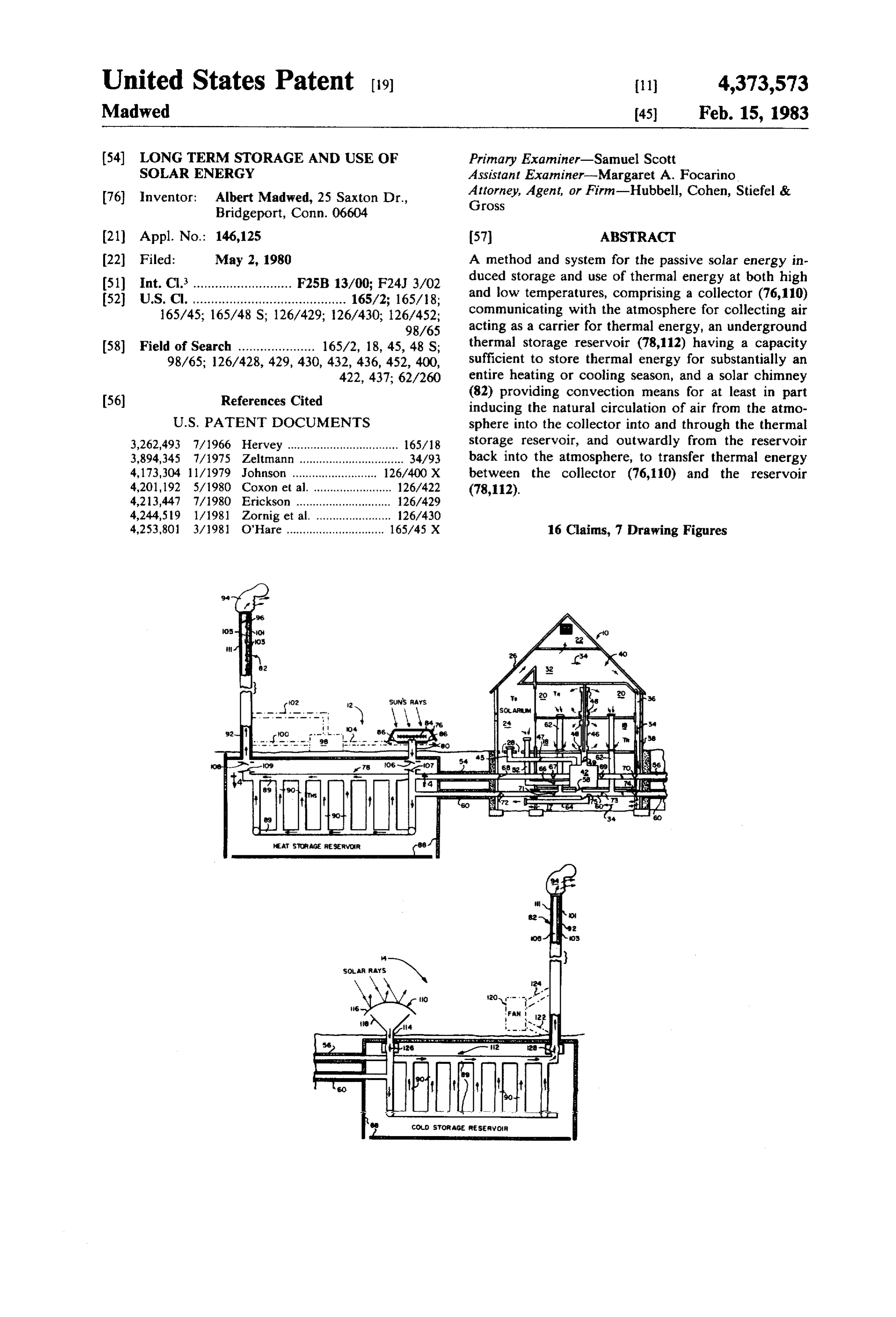
Bridgeport, Conn. 06604 (21) Appl. No.: 146,125 (57) ABSTRACT 22 Filed: May 2, 1980 A method and system for the passive solar energy in 51) Int. Cl. ........................... F25B 13/00; F24J 3/02 duced storage and use of thermal energy at both high (52) U.S. Cl. .......................................... 165/2; 165/18; and low temperatures, comprising a collector (76,110) 165/45; 165/48 S; 126/429; 126/430; 126/452; communicating with the atmosphere for collecting air 98/65 acting as a carrier for thermal energy, an underground 58) Field of Search ..................... 165/2, 18, 45, 48 S; thermal storage reservoir (78,112) having a capacity 98/65; 126/428, 429, 430, 432, 436, 452, 400, sufficient to store thermal energy for substantially an 422, 437; 62/260 entire heating or cooling season, and a solar chimney (56) References Cited (82) providing convection means for at least in part inducing the natural circulation of air from the atmo
3,262,493 7/1966. Hervey .................................. 165/18 storage reservoir, and outwardly from the reservoir 3,894,345 7/1975 Zeltmann ................................ 34/93 back into the atmosphere, to transfer thermal energy 4,173,304 11/1979 Johnson ..... ... 126/400X between the collector (76,110) and the reservoir 4,201,192 5/1980 Coxon et al. ...... 126/422 (78,112).
4,213,447 7/1980 Erickson ........ ... 126/429 4,244,519 1/1981 Zornig et al. ....................... 126/430 4,253,801 3/1981 O'Hare .............................. 165/45 X 16 Claims, 7 Drawing Figures
SoLAR RAYS
Page 2
Drawing sheet — no readable text.
Page 3
Drawing sheet — no readable text.
Page 4
is also circulated to the thermal load in many of these
LONG TERM STORAGE AND USE OF SOLAR instances whereby to reduce the availability for storage ENERGY of thermal energy in the fluid. The Yuan device com
TECHNICAL FIELD
prehends the use of plural heat transfer fluids, e.g., water ammonia, acetone, fluorocarbon refrigerants,
This invention relates to a method and system for the alcohols or liquid metals, and plural, active or pumped storage and use of solar energy, and more particularly systems for effecting heat exchange with the under to the long term storage and utilization of solar energy ground thermal storage zone thereof. Such prior art as, for example, in the seasonal heating and cooling of 10 teachings thus necessitate the use of relatively complex buildings. In one preferred form, the invention may "plumbing', and/or require "active' mechanical sys embody a passive thermal storage system for collecting tems for thermal energy storage and distribution. and storing solar energy over substantially an entire DISCLOSURE OF THE INVENTION winter heating season or summer cooling season, and means for utilizing such energy to supply substantially In accordance with the present invention, a thermal all or most of the cooling or heating requirements of a 15 storage system for storing solar energy (high energy, house or other building during the ensuing summer or e.g. heat, or low energy, e.g. cold) over long term peri winter seasons, respectively. ods is provided, which system comprises a collector for BACKGROUND ART collecting air acting as a carrier for thermal energy. The collector may be in communication with the atmo
Since the 1970's, the ever increasing cost of energy 20 sphere in which event it will collect outside air, or in a derived from fossil fuels has become of critical concern throughout the world. One consequence of the possible closed circulation loop in which event it will collect recirculating air. The system further comprises an un depletion of fossil fuel reserves and the increasing cost derground thermal storage reservoir having a capacity of energy produced therefrom has been heightened sufficient to store thermal energy for long periods of interest in the applications of solar energy, particularly 25 time, preferably for substantially an entire heating or as a means for space and hot water heating for build cooling season of up to six months more or less, and an
A myriad of solar heating methods and systems of with collectorconnecting inlet means the thermal storage reservoir for transferring the air from the collector both the "active' and "passive" types has heretofore to the thermal storage reservoir. Circulation means, been proposed. Of particular current interest are the 30 preferably passive, is provided for circulation of the air large variety of passive solar heating designs in which the collection, storage and distribution of solar energy from the collector, into and through the thermal storage reservoir, and outwardly from the reservoir whereby to in a building or the like is effected by natural means, effect heat transfer from the collector to the reservoir with but minimum use of relatively complex (and ex pensive) solar panels, pumps, fans and other auxiliary 35 during the storage cycle. Finally, outlet means for trans mechanical systems, Illustrative of some of the many ferring thermal energy between the reservoir and a passive solar heating systems described in the prior desired heat load is provided, together with suitable patent literature, for example, are those disclosed in control means for at least at times isolating the reservoir Thomason U.S. Pat. Nos. 3,254,703 and 3,412,728; Hay from the heat load during a heating or cooling season to U.S. Pat. No. 3,563,305; Nilsson U.S. Pat. No. accumulate thermal energy (hot or cold) within the 4,006,856; and Groth U.S. Pat. No. 4,029,258. reservoir throughout such period, and for isolating the Prior solar heating systems provide only for the reservoir from the collector during at least some of the short-term storage of solar energy for no more than a time during succeeding cooling or heating season, re few days at a time. In effect, such systems require fast, spectively, to thereby facilitate the transfer of thermal efficient energy recovery to facilitate use substantially 45 energy from the reservoir to the desired load during concurrently with solar energy collection or, at the that period.
most, after storage of no more than a few days as, for The method and system hereof comprehend the stor instance, during periods of cloudy, rainy or snowy age and use of both relatively high temperature thermal weather. Such systems are inadequate in many regions energy which is available from the hot air of summer which experience long periods of overcast climatic 50 that is preferably, although not necessarily, further conditions. Moreover, by their very nature they require heated by the solar heating of air to elevated tempera the additional provision of complex and expensive aux tures which may be used for winter space heating pur iliary equipment, e.g., conventional heating and/or poses, and relatively low temperature thermal energy cooling systems, as supplemental energy sources. Ac (e.g., that possessed by "cold' winter air at tempera cordingly, prior art solar heating systems have found 55 tures varying from about 0” to 40 F) which may be only limited application to date, used for summer cooling purposes. In popular parlance, The prior art systems all employ some form of short and as used in part herein, the invention is thus applica term energy storage such as a collection of stones or a ble to the storage and distribution of both "heat' and pool of water. The use of the earth as a long term ther "cold', i.e., to the accumulation and use of thermal mal storage reservoir has also been proposed, for exam 60 energy at both relatively high and relatively low tem ple, in Werner U.S. Pat. Nos. 4,024,910 and 4,139,321; perature levels to achieve any desired space heating or Wade U.S. Pat. No. 4,128,204; and Yuan U.S. Pat. No. cooling function.
4,138,995. However, these proposals require the use of Employing the technique of the invention, the heat of relatively complex ducts, channels and/or piping ar the summer season may thus be stored within a heat rangements, or the provision of pumps for the active 65 storage reservoir in the earth with no or little expendi circulation, i.e. pumping, of heat transfer fluids to effect ture of conventionally available energy to be used for thermal energy storage within the underground reser heating purposes during the winter season. Conversely, voirs provided thereby. Moreover, the circulating fluid the system takes the cold of the winter season and stores
Page 5
it within a cold storage reservoir within the earth with itself, or other portions of the system, may derive solar no or little expenditure of conventionally available en energy directly during the season that the reservoir is ergy to be used for cooling purposes during the summer being tapped, whereby to reduce the energy drain on season. The actual periods of alternate storage or use of the reservoir and hance the necessary size thereof. "heat' or "cold' will of course vary, dependent upon 5 While circulation through a reservoir during its stor the particular location at which the invention is utilized. age part of the cycle can be accomplished by a fan or When, for example, the invention is used at a situs in a blower, it is preferred that the circulation be induced in temperate zone, e.g., at a latitude of about 40' (in the part, and most preferably entirely, by passive solar Northern Hemisphere), the "summer season' during means which will induce convection flow through the which heat may be stored will generally encompass the 10 reservoir either as an open loop system or a closed loop period from spring through fall, e.g., from March to system. The passive, long term thermal storage method October; conversely, at such a latitude the "winter and system hereof may be employed for the space heat season', during which cold may be stored employing ing or cooling of any building structure, including the invention, is likely to encompass the period from fall apartment houses, public buildings such as schools, through spring, e.g., from about October to March. 15 commercial buildings, or single or multiple dwelling Accordingly, as used herein the terms "summer season' houses. Alternatively, the invention may be utilized for and "winter season' refer generally to the approximate hot water heating or as a source of refrigeration, or to six month periods during which heat may be stored and operate a heat engine or to generate electricity, rather space cooling may be necessary, or during which cold than for space heating or cooling. It is however pres may be stored and space heating may be necessary, 20 ently preferred to employ the passive solar energy, employing the present invention. thermal storage system of the invention for the alter While the reservoir may be employed to store all of nate, seasonal heating and cooling of private houses or the heat or cold required for the next cooling or heating the like, as more fully described hereinafter. season to render the load independent of climatic condi BRIEF DESCRIPTION OF DRAWINGS tions during that season, it will be apparent, especially 25 when the load is a passively heated solar house, that the The details of the present invention are further de amount of energy required to be stored to render the scribed in connection with the accompanying drawing, house substantially independent of fossil fuel is the in which:
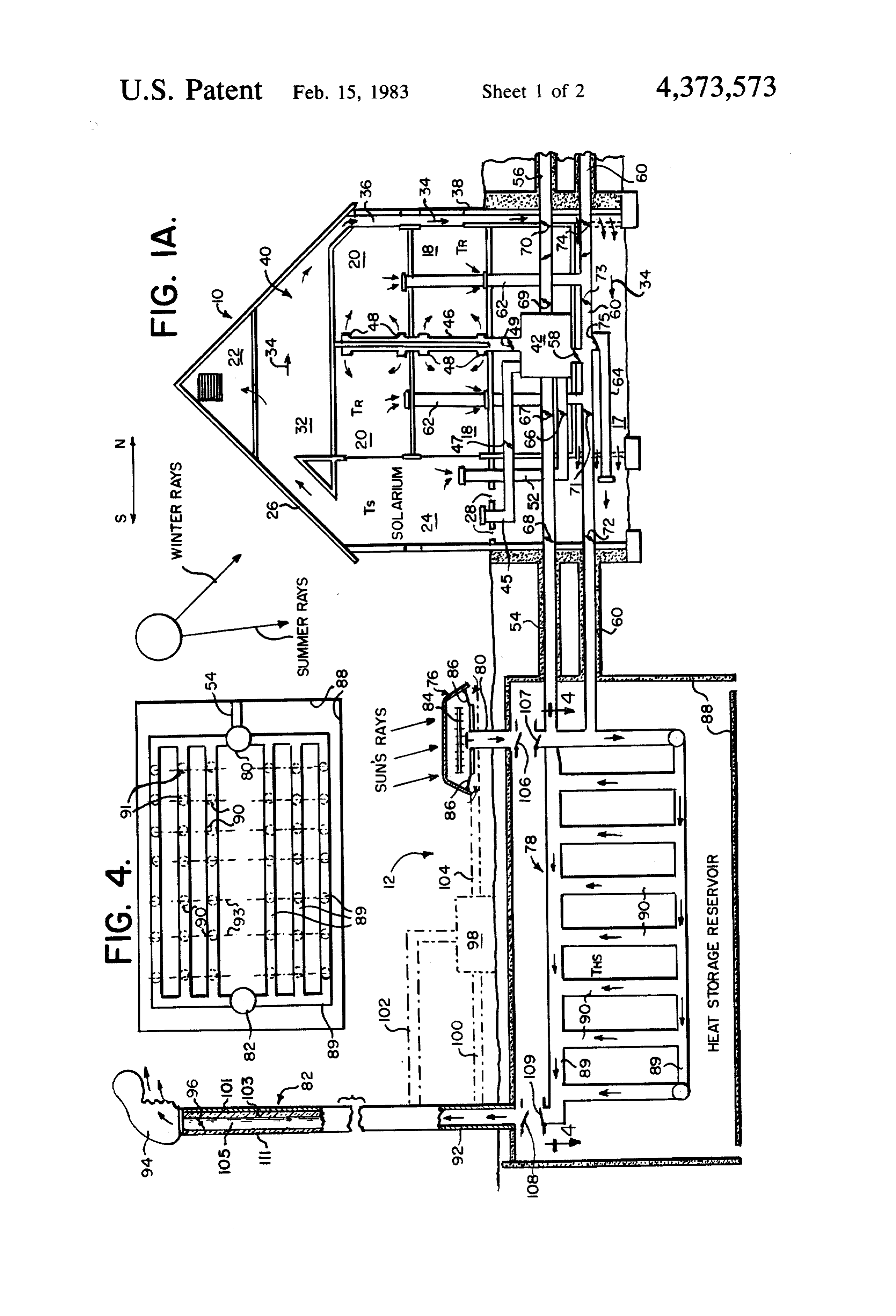
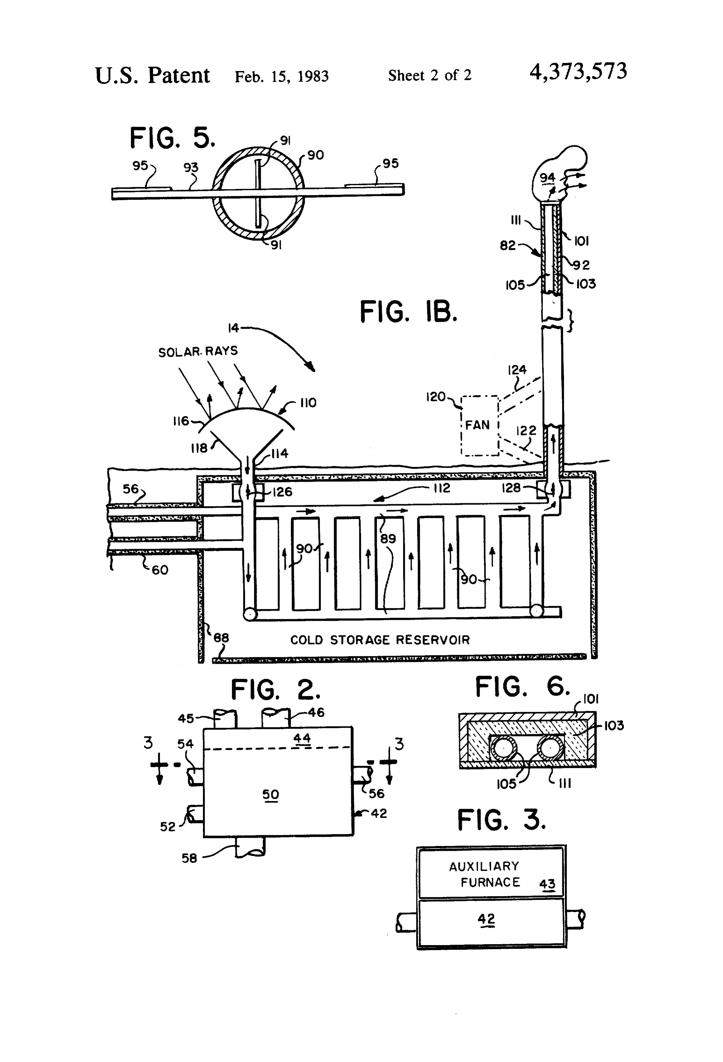
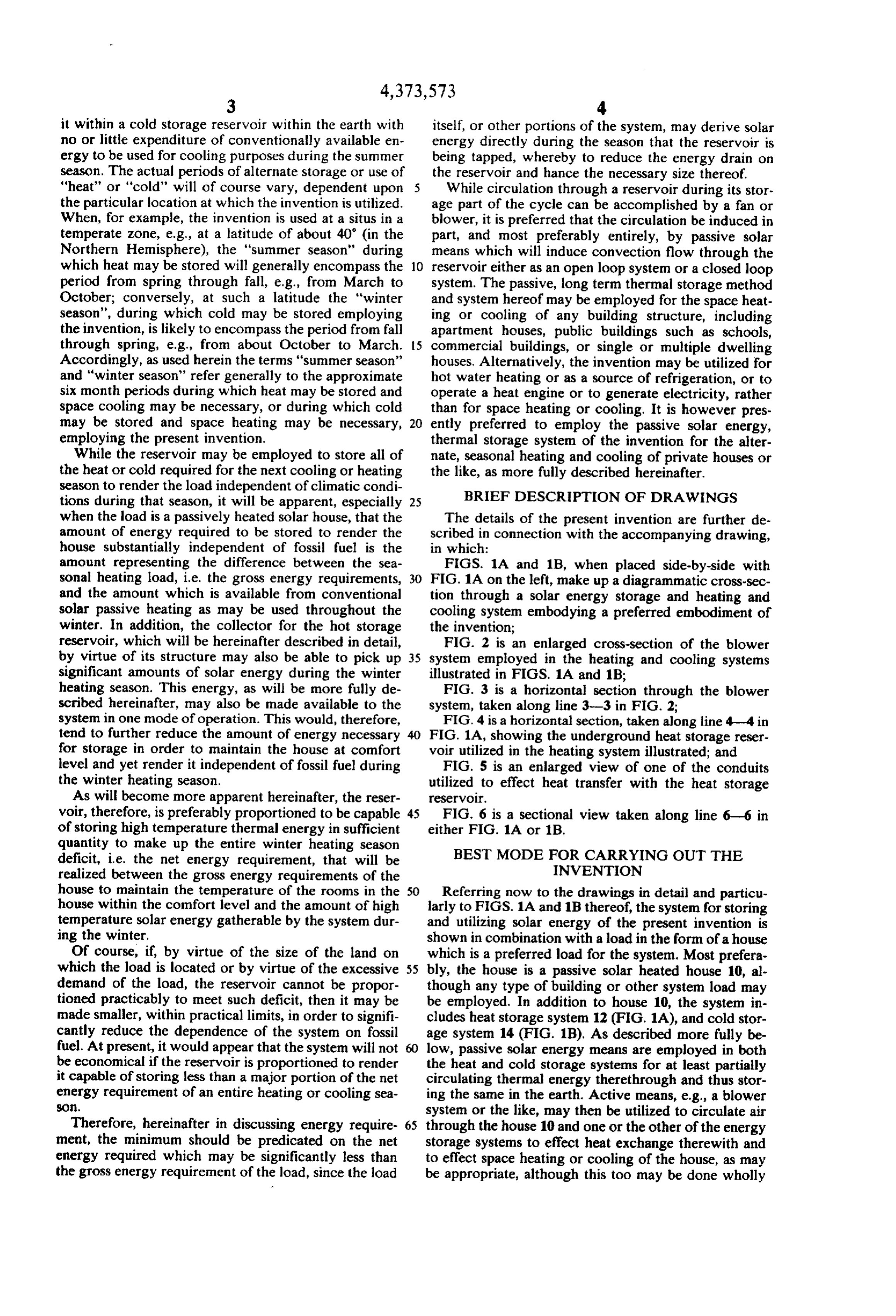
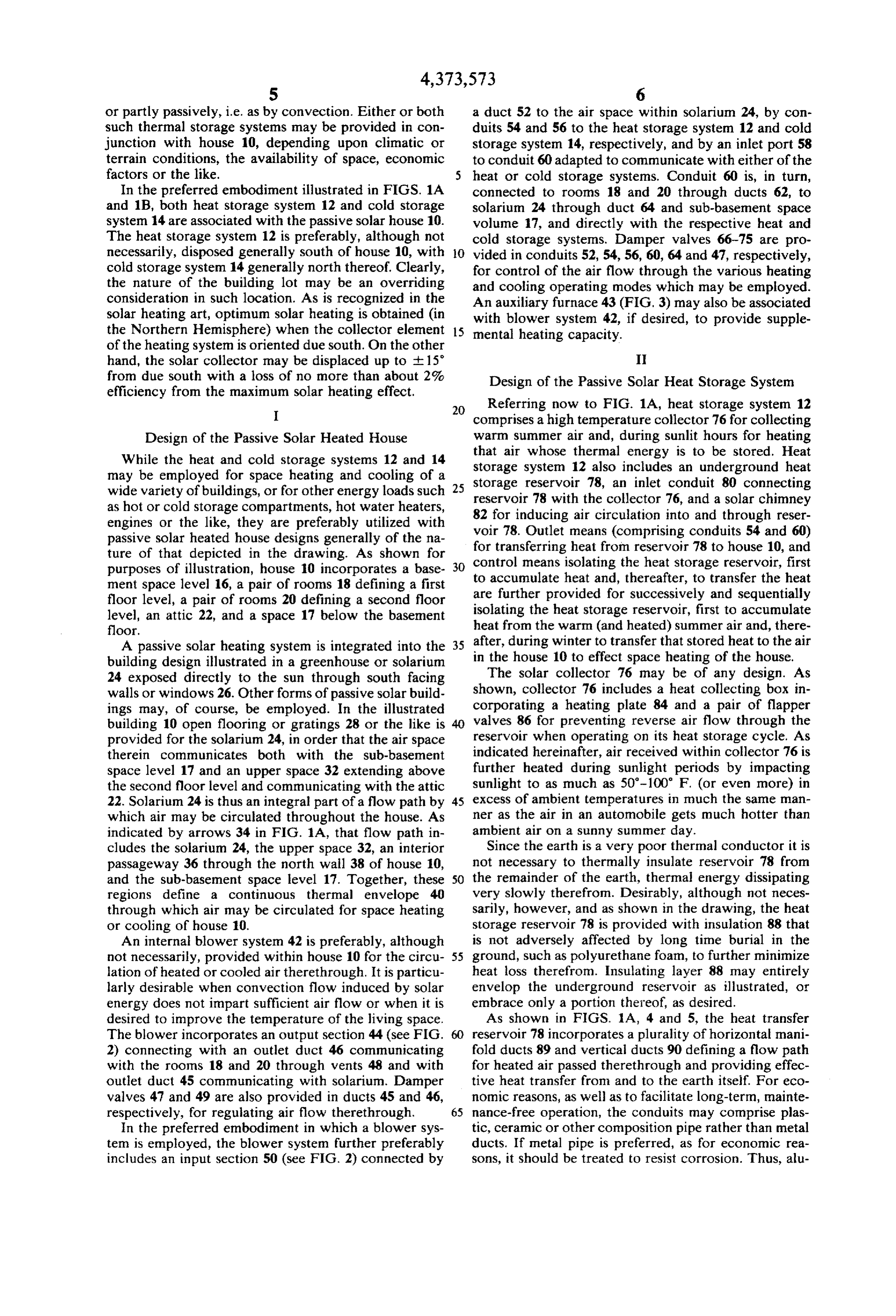
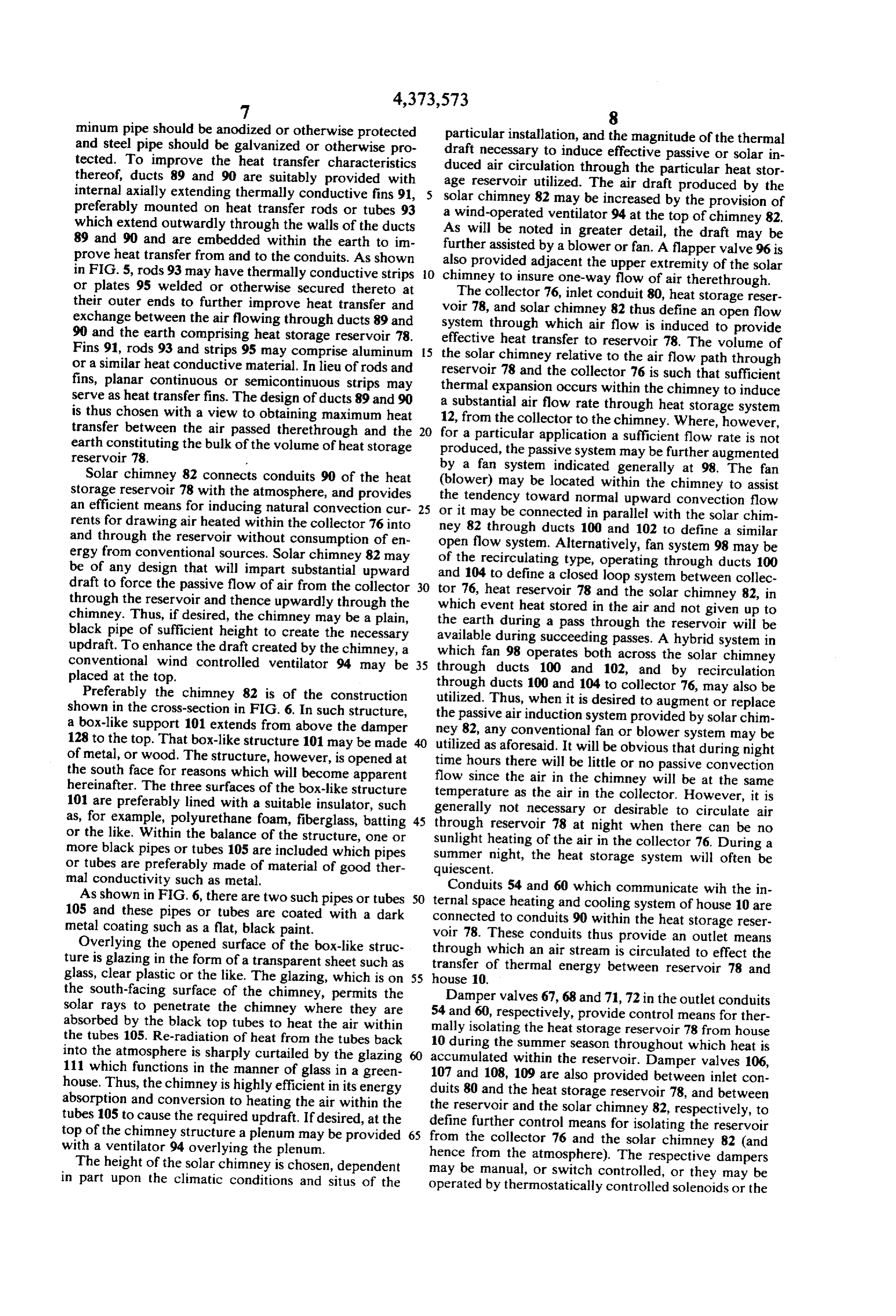
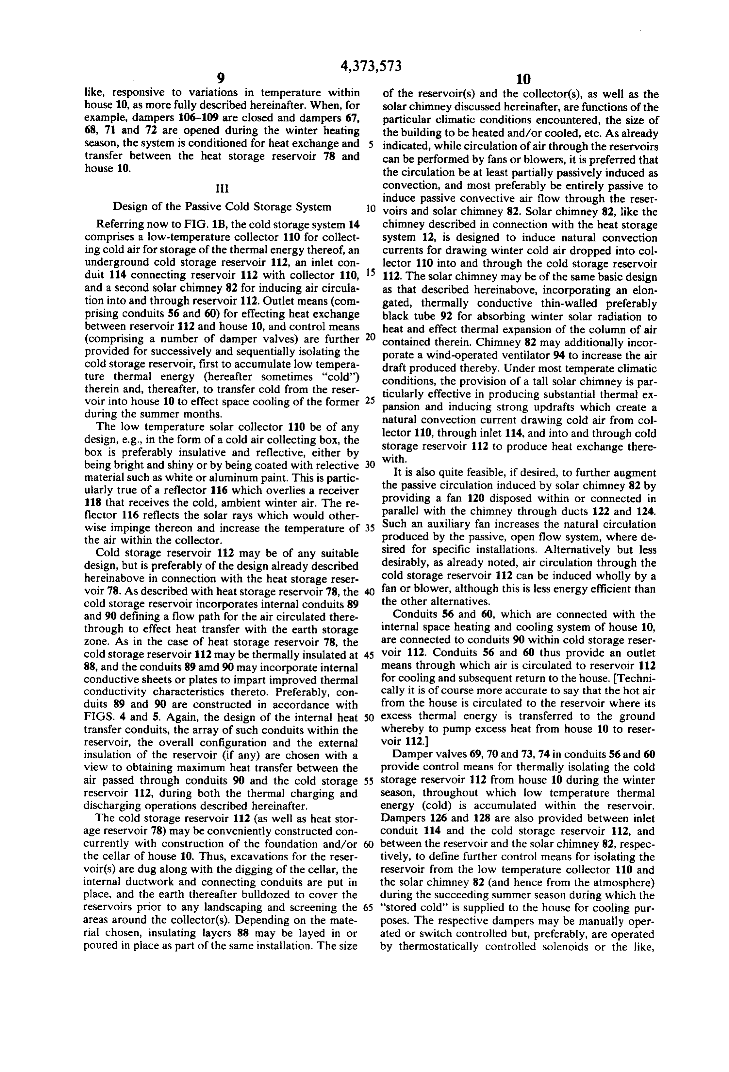
amount representing the difference between the sea FIGS. 1A and 1B, when placed side-by-side with sonal heating load, i.e. the gross energy requirements, 30 FIG. 1A on the left, make up a diagrammatic cross-sec and the amount which is available from conventional tion through a solar energy storage and heating and solar passive heating as may be used throughout the cooling system embodying a preferred embodiment of winter. In addition, the collector for the hot storage the invention;
reservoir, which will be hereinafter described in detail, FIG. 2 is an enlarged cross-section of the blower by virtue of its structure may also be able to pick up 35 system employed in the heating and cooling systems significant amounts of solar energy during the winter illustrated in FIGS. 1A and 1B:
heating season. This energy, as will be more fully de FIG. 3 is a horizontal section through the blower scribed hereinafter, may also be made available to the system, taken along line 3-3 in FIG. 2; system in one mode of operation. This would, therefore, FIG. 4 is a horizontal section, taken along line 4-4 in tend to further reduce the amount of energy necessary 40 FIG. 1A, showing the underground heat storage reser for storage in order to maintain the house at comfort voir utilized in the heating system illustrated; and level and yet render it independent of fossil fuel during FIG. 5 is an enlarged view of one of the conduits the winter heating season. utilized to effect heat transfer with the heat storage As will become more apparent hereinafter, the reser reservoir.
voir, therefore, is preferably proportioned to be capable 45 FIG. 6 is a sectional view taken along line 6-6 in of storing high temperature thermal energy in sufficient either FIG. 1A or 1B.
quantity to make up the entire winter heating season BEST MODE FOR CARRYING OUT THE deficit, i.e. the net energy requirement, that will be INVENTION realized between the gross energy requirements of the house to maintain the temperature of the rooms in the 50 Referring now to the drawings in detail and particu house within the comfort level and the amount of high larly to FIGS. 1A and 1B thereof, the system for storing temperature solar energy gatherable by the system dur and utilizing solar energy of the present invention is ing the winter. shown in combination with a load in the form of a house Of course, if, by virtue of the size of the land on which is a preferred load for the system. Most prefera which the load is located or by virtue of the excessive 55 bly, the house is a passive solar heated house 10, al demand of the load, the reservoir cannot be propor though any type of building or other system load may tioned practicably to meet such deficit, then it may be be employed. In addition to house 10, the system in made smaller, within practical limits, in order to signifi cludes heat storage system 12 (FIG. 1A), and cold stor cantly reduce the dependence of the system on fossil age system 14 (FIG. 1B). As described more fully be fuel. At present, it would appear that the system will not 60 low, passive solar energy means are employed in both be economical if the reservoir is proportioned to render the heat and cold storage systems for at least partially it capable of storing less than a major portion of the net circulating thermal energy therethrough and thus stor energy requirement of an entire heating or cooling sea ing the same in the earth. Active means, e.g., a blower SO. system or the like, may then be utilized to circulate air Therefore, hereinafter in discussing energy require- 65 through the house 10 and one or the other of the energy ment, the minimum should be predicated on the net storage systems to effect heat exchange therewith and energy required which may be significantly less than to effect space heating or cooling of the house, as may the gross energy requirement of the load, since the load be appropriate, although this too may be done wholly
Page 6
or partly passively, i.e. as by convection. Either or both a duct 52 to the air space within solarium 24, by con such thermal storage systems may be provided in con duits 54 and 56 to the heat storage system 12 and cold junction with house 10, depending upon climatic or storage system 14, respectively, and by an inlet port 58 terrain conditions, the availability of space, economic to conduit 60 adapted to communicate with either of the factors or the like. heat or cold storage systems. Conduit 60 is, in turn, In the preferred embodiment illustrated in FIGS. 1A connected to rooms 18 and 20 through ducts 62, to and 1B, both heat storage system 12 and cold storage solarium 24 through duct 64 and sub-basement space system 14 are associated with the passive solar house 10. volume 17, and directly with the respective heat and The heat storage system 12 is preferably, although not cold storage systems. Damper valves 66-75 are pro necessarily, disposed generally south of house 10, with O vided in conduits 52, 54, 56, 60, 64 and 47, respectively, cold storage system 14 generally north thereof. Clearly, for control of the air flow through the various heating the nature of the building lot may be an overriding and cooling operating modes which may be employed. consideration in such location. As is recognized in the An auxiliary furnace 43 (FIG, 3) may also be associated solar heating art, optimum solar heating is obtained (in with blower system 42, if desired, to provide supple the Northern Hemisphere) when the collector element 5 mental heating capacity.
of the heating system is oriented due south. On the other hand, the solar collector may be displaced up to -- 15 I from due south with a loss of no more than about 2% Design of the Passive Solar Heat Storage System efficiency from the maximum solar heating effect.
Referring now to FIG. 1A, heat storage system 12
I comprises a high temperature collector 76 for collecting Design of the Passive Solar Heated House warm summer air and, during sunlit hours for heating While the heat and cold storage systems 12 and 14 storage that air whose thermal energy is to be stored. Heat may be employed for space heating and cooling of a storage system 12 also includes an underground heat wide variety of buildings, or for other energy loads such reservoirreservoir
78 with the collector 76, and a solar chimney as hot or cold storage compartments, hot water heaters, 82 for inducing air circulation into and through reser engines or the like, they are preferably utilized with voir 78. Outlet means (comprising conduits 54 and 60) passive solar heated house designs generally of the na for transferring heat from ture of that depicted in the drawing. As shown for control means isolating thereservoir heat 78 to house 10, and storage reservoir, first purposes of illustration, house 10 incorporates a base to accumulate heat and, thereafter, to transfer the heat ment space level 16, a pair of rooms 18 defining a first are further provided for successively and sequentially floor level, a pair of rooms 20 defining a second floor isolating the heat storage reservoir, first to accumulate level, an attic 22, and a space 17 below the basement heat from the warm (and heated) summer air and, there floor.
A passive solar heating system is integrated into the 35 after, during winter to transfer that stored heat to the air building design illustrated in a greenhouse or solarium in the house 10 to effect space heating of the house. 24 exposed directly to the sun through south facing The solar collector 76 may be of any design. As shown, collector 76 includes a heat collecting box in walls or windows 26. Other forms of passive solar build corporating ings may, of course, be employed. In the illustrated a heating plate 84 and a pair of flapper building 10 open flooring or gratings 28 or the like is valves 86 for preventing reverse air flow through the provided for the solarium 24, in order that the air space reservoir when operating on its heat storage cycle. As therein communicates both with the sub-basement indicated hereinafter, air received within collector 76 is space level 17 and an upper space 32 extending above further heated during sunlight periods by impacting the second floor level and communicating with the attic sunlight to as much as 50-100 F. (or even more) in 22. Solarium 24 is thus an integral part of a flow path by 45 excess of ambient temperatures in much the same man which air may be circulated throughout the house. As ner as the air in an automobile gets much hotter than indicated by arrows 34 in FIG. 1A, that flow path in ambient air on a sunny summer day.
cludes the solarium 24, the upper space 32, an interior Since the earth is a very poor thermal conductor it is passageway 36 through the north wall 38 of house 10, not necessary to thermally insulate reservoir 78 from and the sub-basement space level 17. Together, these 50 the remainder of the earth, thermal energy dissipating regions define a continuous thermal envelope 40 very slowly therefrom. Desirably, although not neces through which air may be circulated for space heating sarily, however, and as shown in the drawing, the heat or cooling of house 10. storage reservoir 78 is provided with insulation 88 that An internal blower system 42 is preferably, although is not adversely affected by long time burial in the not necessarily, provided within house 10 for the circu 55 ground, such as polyurethane foam, to further minimize lation of heated or cooled air therethrough. It is particu heat loss therefrom. Insulating layer 88 may entirely larly desirable when convection flow induced by solar envelop the underground reservoir as illustrated, or energy does not impart sufficient air flow or when it is embrace only a portion thereof, as desired. desired to improve the temperature of the living space. As shown in FIGS. 1A, 4 and 5, the heat transfer The blower incorporates an output section 44 (see FIG. reservoir 78 incorporates a plurality of horizontal mani 2) connecting with an outlet duct 46 communicating fold ducts 89 and vertical ducts 90 defining a flow path with the rooms 18 and 20 through vents 48 and with for heated air passed therethrough and providing effec outlet duct 45 communicating with solarium. Damper tive heat transfer from and to the earth itself. For eco valves 47 and 49 are also provided in ducts 45 and 46, nomic reasons, as well as to facilitate long-term, mainte respectively, for regulating air flow therethrough. 65 nance-free operation, the conduits may comprise plas In the preferred embodiment in which a blower sys tic, ceramic or other composition pipe rather than metal tem is employed, the blower system further preferably ducts. If metal pipe is preferred, as for economic rea includes an input section 50 (see FIG. 2) connected by sons, it should be treated to resist corrosion. Thus, alu
Page 7
minum pipe should be anodized or otherwise protected particular installation, and the magnitude of the thermal and steel pipe should be galvanized or otherwise pro draft tected. To improve the heat transfer characteristics ducednecessary to induce effective passive or solar in thereof, ducts 89 and 90 are suitably provided with age reservoir utilized.through air circulation the particular heat stor
The air draft produced by the internal axially extending thermally conductive fins 91, solar chimney 82 may be increased by the provision of preferably mounted on heat transfer rods or tubes 93 a wind-operated which extend outwardly through the walls of the ducts As will be notedventilator
94 at the top of chimney 82.
greater detail, the draft may be 89 and 90 and are embedded within the earth to im further assisted by a blower or fan. A flapper valve 96 is prove heat transfer from and to the conduits. As shown also provided adjacent the upper extremity of the solar in FIG. 5, rods 93 may have thermally conductive strips O chimney to insure one-way flow of air therethrough. or plates 95 welded or otherwise secured thereto at The collector 76, inlet conduit 80, heat storage reser their outer ends to further improve heat transfer and voir 78, and solar chimney 82 thus define exchange between the air flowing through ducts 89 and system through which air flow is inducedantoopen flow provide 90 and the earth comprising heat storage reservoir 78. effective heat transfer to reservoir 78. The volume of Fins 91, rods 93 and strips 95 may comprise aluminum 5 the solar chimney relative to the air flow path through or a similar heat conductive material. In lieu of rods and reservoir 78 and the collector 76 is such that sufficient fins, planar continuous or semicontinuous strips may serve as heat transfer fins. The design of ducts 89 and 90 thermal
expansion occurs within the chimney to induce substantial air flow rate through heat storage system is thus chosen with a view to obtaining maximum heat 12, from the collector to the chimney. Where, however, transfer between the air passed therethrough and the 20 for a particular application earth constituting the bulk of the volume of heat storage produced, the passive systema may sufficient flow rate is not be further augmented
by a fan system indicated
Solar chimney 82 connects conduits 90 of the heat (blower) may be located within the chimneygenerally at 98. The fan storage reservoir 78 with the atmosphere, and provides the tendency toward normal upward convection to assist an efficient means for inducing natural convection cur 25 or flow it may be connected in parallel with the rents for drawing air heated within the collector 76 into ney 82 through ducts 100 and 102 to define a similar solar chim and through the reservoir without consumption of en open ergy from conventional sources. Solar chimney 82 may of theflow system. Alternatively, fan system 98 may be recirculating type, operating through ducts 100 be of any design that will impart substantial upward and 104 to define a closed loop system between collec draft to force the passive flow of air from the collector 30 tor 76, heat reservoir 78 and through the reservoir and thence upwardly through the which event heat stored in thethe air solar chimney 82, in and not given up to chimney. Thus, if desired, the chimney may be a plain, the earth during a pass through the black pipe of sufficient height to create the necessary available during succeeding passes. A reservoir hybrid will be system in updraft. To enhance the draft created by the chimney, a which fan 98 operates both across the solar chimney conventional wind controlled ventilator 94 may be 35 through ducts 100 and 102, and by recirculation placed at the top.
Preferably the chimney 82 is of the construction through utilized.
ducts 100 and 104 to collector 76, may also be
Thus, when it is desired to augment or replace shown in the cross-section in FIG. 6. In such structure, the passive air induction a box-like support 101 extends from above the damper ney 82, any conventionalsystem fan or provided by solar chim blower system may be 128 to the top. That box-like structure 101 may be made utilized as aforesaid. It will be obvious that during night of metal, or wood. The structure, however, is opened at time hours there will be little or no passive the south face for reasons which will become apparent flow since the air in the chimney will be atconvection the same hereinafter. The three surfaces of the box-like structure 101 are preferably lined with a suitable insulator, such generally not necessary or desirable to circulate itairis temperature as the air in the collector. However, as, for example, polyurethane foam, fiberglass, batting 45 through reservoir 78 at night when there can be no or the like. Within the balance of the structure, one or more black pipes or tubes 105 are included which pipes sunlight heating of the air in the collector 76. During a or tubes are preferably made of material of good ther quiescent.night, the heat storage system will often be summer mal conductivity such as metal. Conduits 54 and 60 which communicate with the in As shown in FIG. 6, there are two such pipes or tubes 50 ternal space heating and cooling system of house 10 are 105 and these pipes or tubes are coated with a dark connected to conduits 90 within the heat storage reser metal coating such as a flat, black paint. voir 78. These conduits thus provide an outlet means Overlying the opened surface of the box-like struc through which an air stream is circulated to effect the ture is glazing in the form of a transparent sheet such as transfer of glass, clear plastic or the like. The glazing, which is on 55 house 10. thermal energy between reservoir 78 and the south-facing surface of the chimney, permits the solar rays to penetrate the chimney where they are 54Damper valves 67, 68 and 71, 72 in the outlet conduits and 60, respectively, provide control means for ther absorbed by the black top tubes to heat the air within mally isolating the heat storage reservoir 78 from house the tubes 105. Re-radiation of heat from the tubes back 10 during the summer season throughout which heat is into the atmosphere is sharply curtailed by the glazing accumulated 111 which functions in the manner of glass in a green 107 and 108, within 109 are the reservoir. Damper valves 106, also provided between inlet con house. Thus, the chimney is highly efficient in its energy duits 80 and the heat storage reservoir 78, and between absorption and conversion to heating the air within the the reservoir and the solar chimney 82, respectively, to tubes 105 to cause the required updraft. If desired, at the top of the chimney structure a plenum may be provided 65 define further control means for isolating the reservoir from the collector 76 and the solar chimney 82 (and with a ventilator 94 overlying the plenum.
The height of the solar chimney is chosen, dependent hence from the atmosphere). The respective dampers in part upon the climatic conditions and situs of the operatedmanual, may be or switch controlled, or they may be by thermostatically controlled solenoids or the
Page 8
like, responsive to variations in temperature within of the reservoir(s) and the collector(s), as well as the house 10, as more fully described hereinafter. When, for solar chimney discussed hereinafter, are functions of the example, dampers 106-109 are closed and dampers 67, particular climatic conditions encountered, the size of 68, 71 and 72 are opened during the winter heating the building to be heated and/or cooled, etc. As already season, the system is conditioned for heat exchange and indicated, while circulation of air through the reservoirs transfer between the heat storage reservoir 78 and can be performed by fans or blowers, it is preferred that house 10. the circulation be at least partially passively induced as I convection, and most preferably be entirely passive to
Design of the Passive Cold Storage System induce passive convective air flow through the reser O voirs and solar chimney 82. Solar chimney 82, like the
Referring now to FIG. 1B, the cold storage system 14 chimney described in connection with the heat storage comprises a low-temperature collector 110 for collect system 12, is designed to induce natural convection ing cold air for storage of the thermal energy thereof, an currents for drawing winter cold air dropped into col underground cold storage reservoir 112, an inlet con 15 lector 110 into and through the cold storage reservoir duit 114 connecting reservoir 112 with collector 110, 112. The solar chimney may be of the same basic design and a second solar chimney 82 for inducing air circula as that described hereinabove, incorporating an elon tion into and through reservoir 112. Outlet means (com gated, thermally conductive thin-walled preferably prising conduits 56 and 60) for effecting heat exchange black tube 92 for absorbing winter solar radiation to between reservoir 112 and house 10, and control means heat and effect thermal expansion of the column of air (comprising a number of damper valves) are further 20 contained therein. Chimney 82 may additionally incor provided for successively and sequentially isolating the porate a wind-operated ventilator 94 to increase the air cold storage reservoir, first to accumulate low tempera draft produced thereby. Under most temperate climatic ture thermal energy (hereafter sometimes "cold") conditions, the provision of a tall solar chimney is par therein and, thereafter, to transfer cold from the reser ticularly effective in producing substantial thermal ex voir into house 10 to effect space cooling of the former 25 pansion and inducing strong updrafts which create a during the summer months. natural convection current drawing cold air from col The low temperature solar collector 110 be of any lector 110, through inlet 114, and into and through cold design, e.g., in the form of a cold air collecting box, the storage reservoir 112 to produce heat exchange there box is preferably insulative and reflective, either by being bright and shiny or by being coated with relective 30 with.
material such as white or aluminum paint. This is partic theItpassive is also quite feasible, if desired, to further augment circulation induced by solar chimney 82 by ularly true of a reflector 116 which overlies a receiver providing a fan 120 disposed within or connected in 118 that receives the cold, ambient winter air. The re flector 116 reflects the solar rays which would other parallel with the chimney through ducts 122 and 124. wise impinge thereon and increase the temperature of 35 Such an auxiliary fan increases the natural circulation the air within the collector. produced by the passive, open flow system, where de Cold storage reservoir 112 may be of any suitable sired for specific installations. Alternatively but less design, but is preferably of the design already described desirably, as already noted, air circulation through the hereinabove in connection with the heat storage reser cold storage reservoir 112 can be induced wholly by a voir 78. As described with heat storage reservoir 78, the fan or blower, although this is less energy efficient than cold storage reservoir incorporates internal conduits 89 the other alternatives.
and 90 defining a flow path for the air circulated there Conduits 56 and 60, which are connected with the through to effect heat transfer with the earth storage internal space heating and cooling system of house 10, zone. As in the case of heat storage reservoir 78, the are connected to conduits 90 within cold storage reser cold storage reservoir 112 may be thermally insulated at 45 voir 112. Conduits 56 and 60 thus provide an outlet 88, and the conduits 89 amid 90 may incorporate internal means through which air is circulated to reservoir 112 conductive sheets or plates to impart improved thermal for cooling and subsequent return to the house. Techni conductivity characteristics thereto. Preferably, con cally it is of course more accurate to say that the hot air duits 89 and 90 are constructed in accordance with from the house is circulated to the reservoir where its FIGS. 4 and 5. Again, the design of the internal heat 50 excess thermal energy is transferred to the ground transfer conduits, the array of such conduits within the whereby to pump excess heat from house 10 to reser reservoir, the overall configuration and the external voir 112.
insulation of the reservoir (if any) are chosen with a Damper valves 69, 70 and 73, 74 in conduits 56 and 60 view to obtaining maximum heat transfer between the provide control means for thermally isolating the cold air passed through conduits 90 and the cold storage 55 storage reservoir 112 from house 10 during the winter reservoir 112, during both the thermal charging and season, throughout which low temperature thermal discharging operations described hereinafter. energy (cold) is accumulated within the reservoir. The cold storage reservoir 112 (as well as heat stor Dampers 126 and 128 are also provided between inlet age reservoir 78) may be conveniently constructed con conduit 114 and the cold storage reservoir 112, and currently with construction of the foundation and/or between the reservoir and the solar chimney 82, respec the cellar of house 10. Thus, excavations for the reser tively, to define further control means for isolating the voir(s) are dug along with the digging of the cellar, the reservoir from the low temperature collector 110 and internal ductwork and connecting conduits are put in the solar chimney 82 (and hence from the atmosphere) place, and the earth thereafter bulldozed to cover the during the succeeding summer season during which the reservoirs prior to any landscaping and screening the 65 "stored cold' is supplied to the house for cooling pur areas around the collector(s). Depending on the mate poses. The respective dampers may be manually oper rial chosen, insulating layers 88 may be layed in or ated or switch controlled but, preferably, are operated poured in place as part of the same installation. The size by thermostatically controlled solenoids or the like,
Page 9
responsive to variations in temperature within house 10, and the high temperature collector, or through ducts as more fully described hereinafter. Thus, when valves 100, 102 and 104 as part of a hybrid circulating system. 126 and 128 are closed and valves 69, 70 and 73, 74 are Again, as noted, circulation may be wholly induced by opened during the summer cooling season, the system is fan or blower without departing from this invention. conditioned to permit heat exchange between the cold However, this is not preferred. storage reservoir 112 and the living space within house The heated air stream thus passed through heat stor
age reservoir 78 gradually raises the temperature of the
IV reservoir to charge the reservoir with heat. This charg Operation of the Solar Heating System ing operation may take place over the entire summer 10 period, i.e., during the period from March to October
A. Operation of the Heat Storage System depending upon the climatic conditions at the particular Operation of the heat storage system 12 is effected by installation.
initially thermally charging the heat storage reservoir Preferably, and for most efficient operation, valves or 78 during the summer season when the ambient temper dampers 106 and 108 are opened only when the air ature is about 60 F. or higher. During this period solar 5 temperature within collector 76 exceeds the air temper radiation may increase the temperature of heating plate 84 within collector 76 possibly to hundreds of degrees ature within heat storage reservoir 78 by some predeter F., correspondingly increasing the temperature of the greater value, mined i.e., referring to FIG. 1A, when T1 is than THS by some predetermined value. For air within the heat collecting box defined by the collec example, if T decreases below THS in the late afternoon tor. To permit heat exchange with the thus heated air, 20 or preferably damper valves 67, 68 and 71, 72 in conduits ingevening reverse the valves 106 and 108 are closed, prevent heat flow to the atmosphere. If desired,
connecting heat storage reservoir 78 with collector 76 which actuateT1suitable temperatures and THS may be sensed by thermostats control mechanisms that auto and the solar chimney 82, respectively, are open. The matically operate dampers 106 and 108. Similarly, flap valves may be operated manually or by conventional per valve 106 prevents hot air
from escaping outwardly motor means such as solenoids. The solenoids may be from reservoir 78 through collector 76, and flapper controlled in whole or in part by thermostats, manual valve 109 precludes a downdraft from solar chimney 82 switches or by a programmable microprocessor. With from entering reservoir 78.
the damper valves in the condition as above described, the reservoir is isolated from the house during the heat 30 After the reservoir is sufficiently charged, preferably storage part of the cycle. This is normally preferred. so that above 100 F. air can be delivered to the house However, there may be times when it might be desir during the entire heating season, it may be utilized for able to collect heat in the house and circulate the excess winter space heating of house 10. This temperature will to the storage reservoir, particularly on a warm, sunny depend on the design of the house 10 and heat storage winter day, for example. Such operation comes within 35 reservoir. In such an instance, during the heating sea the purview of this invention and it is not intended in son, valves 106-109 are closed, and valves 67, 68 and 71, any way to be excluded. At the same time radiation 72 in conduits 54 and 60 will be opened to permit heat heating of the solar chimney 82 effects thermal expan exchange with the living space within house 10, as indi sion of the long column of air within the chimney, pro cated hereinafter.
ducing an updraft therein which creates a pressure drop B. The Normal Passive Solar Heating Mode within reservoir 78. The pressure differential “pulls While the particular thermal load forms no part of down' air heated within collector 76 into the reservoir, this invention by itself, as indicated a preferred load is which in turn induces the flow of ambient air into the passive solar house 10. When the temmperature (TR in collector to continue the process. There is thus pro FIG. 1A) within the living space in house 10 is at the duced a natural convection current which circulates the 45 "comfort level" (e.g., within the range of from about hot air from collector 76, through the inlet conduit 80 60' F. to 75' F., depending upon the time of day and and down into and through the heat storage reservoir time of the year) the house blower system 42 is off and 78, prior to being returned to the atmosphere upwardly valves 47, 49, 58 and 75 into outlet ducts 46 and 64 through the solar chimney. As indicated, the draft thus connecting the blower system with the house living created pulls more ambient air through flapper valves 50 space, are closed. Similarly, as indicated hereinabove 86 into collector 76, continuing the process throughout damper valves 67 and 68 in conduit 54, and dampers 71 the sunlit day. During the night, with no sunlight, the and 72 in conduit 60 leading from the heat storage reser heat storage system will automatically shut down, un voir 78 are preferably closed. In this manner heat trans less assisted by a blower or by wind as noted below. fer from the heat storage reservoir into house 10 is The updraft produced by the solar chimney is prefer 55 precluded. Finally, damper valves 69 and 70 in conduit ably augmented by the operation of the wind-operated 56, and valves 73 and 74 in conduit 60, leading to the ventilator 94 mounted thereon. In addition fan system cold storage reservoir 112 are also preferably closed. 98 may be provided to further increase the desired cir Heat transfer from house 10 into the cold storage reser culation, e.g., during very still, hot days when there is voir is thus also precluded.
little wind effect and thermal expansion through the Natural circulation through the thermal envelope 40 solar chimney is not sufficiently greater than the ther of house 10 is thus obtained, solar energy passively mal expansion effect at collector 76 to provide an ade obtained within solarium 24 being conveyed naturally quate natural convection current from the collector by convection upwardly to upper space 32, and thence through the reservoir. As indicated hereinabove, when downward through interior passageway 36 and then the auxiliary fan system 98 is thus employed it may 65 through sub-basement space level 17 back into the liv operate through ducts 100 and 102 as part of an open ing space of the house 10. Other than passive solar heat circulation system, through ducts 100 and 104 to define ing and air circulation produced within solarium 24, a closed circulation system between the solar chimney preferably no active means for heating or cooling house
Page 10
10 are employed in this mode of operation. If there is tive systems, either alone or in combination, may be excess heat in the circulating air, that heat will be given automatically actuated, depending upon the heat loads, up to the walls, floor, fixtures and earth in the sub-base by a preprogrammed circuit controller operating in ment for short term storage to heat the air as it circu response to thermostats located in the solarium and in lates during the evening. This of course is common to rooms 18 and 20, which in turn will energize solenoids most prior art passive solar houses although the base or other motor means controlling the valves or damp ment reservoir may be more elaborate in such prior art ers. If desired, the entire operation may be controlled structures. through the means of logic circuitry such as, for exam C. Solar Heating Using the Solarium-Blower System ple, a microprocessor. Alternatively, additional heat When the temperature TR within rooms 18 and 20 10 may be fed to the system through duct 46 from auxiliary dips below the comfort level and the temperature in the furnace 43, or electric heating, as desired. The auxiliary solarium (TS in FIG. 1A) nevertheless exceeds the com furnace may be utilized in conjunction with either or fort level by a predetermined differential, the blower both of the two heating systems described herein. If it is system 42 is activated to circulate the warmer air from also desired to heat the solarium space, dampers 47 and the solarium directly to rooms 18 and 20 defining the 15 75 are additionally opened and blower system will house living space. For this purpose damper 66 in duct pump air from heat reservoir through the solarium and 52, damper 49 in duct 46 and damper 75 opening into back to heat reservoir, thus delivering heat to solarium. conduit 64, are opened. The opening of the dampers or V valves may be achieved by the operation of solenoids coupled to the respective dampers. In turn, the sole 20 Operation of the Solar Cooling System noids may be operated by a power unit which is acti A. Operation of the Cold Storage System wated, for example, by thermometer when TR and Ts are at the levels above noted. The air heated by solar to Operation of the cold storage system 14 is analogous radiation within solarium 24 is thus drawn through duct hereinabove. Thus,ofduring the operation heat storage system 12, described the winter season cold air is 52 into blower system 42, from whence the heated air is 25 dropped into the low temperature collector 110, from circulated through rooms 18 and 20. Air removed from which it flows into and through cold storage reservoir rooms 18 and 20 through ducts 62 flows into conduit 60 112 (wherein it charges the reservoir with "cold"), and and thence through conduit 64 into the sub-basement is drawn back into the atmosphere through the solar space volume 17 (where it mixes with air passing through thermal envelope 40), and is recycled to sola 30 chimney 82. This procedure is initiated by opening valve or damper 126 in inlet conduit 114, and valve 128 rium 24. The temperature in the basement may be some intermediate what elevated due to its storage effect, as above noted. chimney, under the cold storage reservoir and the solar The blower system 42 thus effects active circulation conditions in which natural air circula between the passive-solar heated solarium and rooms 18 tion is induced from the collector to the solar chimney as by sunlight impinging on the solar chimney to cause and 20, responsive preferably to thermostatic controls 35 an updraft. At the same time valves or dampers 70 and sensing the differential temperatures therein.
D. Solar Heating Using the Heat Storage-Blower 74 in conduits 56 and 60 are closed to preclude prema System ture heat exchange between reservoir 112 and house 10 When the temperature in rooms 18 and 20 is below prior As to use for summer space cooling.
previously described, such circulation may be the comfort level, and the solarium temperature is not initiated by thermal expansion of the tall column of air sufficiently above that level to provide sufficient heat by itself to raise the temperature in rooms 18 and 20 within chimney 82 upon solar heating thereof. In addi back into the comfort range, as indicated by suitable tion, excellent flow may be induced, even during cold temperature sensing means in the two locations, it is winter nights, by the further action of wind-operated necessary to draw heat from the heat storage system 12 45 ventilator 94 on chimney 82.
to maintain the living space within house 10 at comfort After prolonged heat exchange with the cold air able temperature levels. For this purpose valves or flow, the earth in reservoir 112 is cooled to its lowest dampers 67 and 68 in conduit 54, and valves or dampers value, e.g., to temperatures which may vary from as 71 and 72 in conduit 60, connected to the heat storage low as -20 to as much as 40' F., depending upon the reservoir are opened. At the same time valves or damp 50 situs of the particular installation. Where the reservoir is ers 49 in duct 46 is opened and blower system 42 is so designed as to have an appreciable water content, activated. The blower thus circulates air into and freezing of the ground water with consequent dissipa through rooms 18 and 20, the air being exhausted there tion of the latent heat of fusion will impart yet greater from through ducts 62, passing through conduit 60, and cooling capacity to the cold storage reservoir. flowing through heat storage reservoir 78 where it is 55 When the ambient atmospheric temperature exceeds heated. The thus heated air is recirculated to house 10 the temperature within cold storage reservoir 112, through conduit 54, whence it is fed by blower system valves or dampers 126 and 128 are closed to isolate the 42 back into rooms 18 and 20 to increase the tempera reservoir from the atmosphere. Thereafter, when it is ture therein to maintain the desired comfort level. desired to employ the reservoir for space cooling dur If it is desired to utilize both the solar energy col ing the summer season, valves or dampers 70 and 74 in lected in solarium 24 and that stored in heat storage conduits 56 and 60 are opened to facilitate heat ex reservoir 78 for space heating, damper 66 induct 52 and change with the living space within house 10 as de damper 75 in duct 64 may be opened in addition to scribed below.
dampers 67, 68, 71, 72 and 49. In this manner, both B. Normal Passive Solar Cooling Mode heated air removed from solarium 24 and that produced 65 When, during the summer season, the room tempera by heat exchange within heat storage reservoir 78 are ture TR within rooms 18 and 20 of house 10 is within the pumped into and through rooms 18 and 20 defining the comfort range the living space within the house may be living space within house 10. The use of these alterna isolated from both the passive-solar heating means
Page 11
within solarium 24 and the cold storage reservoir 112 not overload the entire system. Thus, during extreme merely by closing dampers 49, 66, 69, 70, 73,74, 58 and hot spells, the major portion of the house, made up of 75, respectively. Passive flow through thermal enve the interior rooms 18 and 20, can be kept at a comfort lope 40 is thus obtained in the same manner as previ able ously described in connection with the Normal Passive 5 cool level the without overloading the system by trying to solarium. However, during evenings or during
Solar Heating Mode of operation. Alternatively, with less intense hot periods, the solarium may be cooled as windows or outside doors open the air heated in sola well. As is true with the operation of most of the damp rium 24 can be vented out through space 22 by opening ers, the damper 66 may be automatically operated or the damper between space 34 and space 22 to prevent the recirculation of the heated air, This will cause a 10 may be operated by a manual switch controlling a sole draft which will impart some cooling to occupants. noid or other motor means for opening or closing C. Solar Cooling Using Cold Storage-Blower System damper 66, or if desired, the damper 66 may be manu When temperature detection means detect uncom ally operated. Moreover, if desired, conventional air fortably high temperatures in TR in rooms 18 and 20 of conditioning means may be incorporated within the the house 10, advantage of the "cold" stored in the cold 15 system in a manner similar to the furnace means de storage reservoir may be taken to reduce that tempera scribed above for supplementing the cold storage sys ture to the comfort level. As will be seen hereinafter, tem during extreme hot temperature periods. Also, if it additional steps may be taken to cool down the temper is desired to cool the solarium space only, dampers 47 ature in the solarium as well. To reduce the temperature and 75 may be opened, dampers 69, 70, 73 and 74 are in the room 18 and 20 within the air circulation enve 20 open, and blower system will move cold air from the lope defined by the solarium, space 32, space 34 and the cold reservoir into the solarium and back. It is obvious space within the basement, first dampers 126 and 128 that other combinations of these actions can be effected. connecting the cold storage reservoir respectively to VI the cold air collector 110 and the cold air chimney 82 are closed to block passive circulation through the cold 25 System Design Capacity storage reservoir. This action is done on a more or less As described hereinabove, use of the heat storage seasonal basis with the dampers 126 and 128 closed from system 12 facilitates summer heat storage and winter April through September. Since dampers 126 and 128 heating, and use of the cold storage system 14 permits are normally only operated once every six months, they winter cold storage and summer cooling of the air space may be manual. Alternatively, they may be motor oper 30 within house 10. Either system may be used alone or ated, such as by solenoids, which in turn are controlled both may be used in conjunction to provide a substan by manual switches within the house 10 or by some tially year-round heating and cooling system for house overriding circuit controller. Assuming the storage O.
circuit for the cold storage reservoir is closed as de The efficacy of the passive solar energy storage sys scribed to permit circulation of the air from the house 35 tem of the invention may be illustrated by the following through the reservoir for cooling and then back to the calculations, based upon average daily solar radiation house, the dampers 69,70, 73 and 74 are opened to open data for a situs at New York City (40' North latitude). the ducts 56 and 60 between the house and the reser Such radiation on a horizontal surface in B.T.U.'s per voir, damper 49 between the blower system 42 and duct day per square foot is as follows: 46 is opened, and damper 58 between the blower system and duct 60 is at least partially opened to permit cool air January S40 July 1938 circulation from the duct 60 into the blower 42 and then
through the inner portion of the house. Through the March 180 September 1349 dampers operated to the described condition, when the April 426 October 977 blower is energized as would result by suitable tempera 45 May 738 November 598 ture detection means activating a control mechanism June 1994 December 476 upon sensing an over-temperature condition, hot air from the rooms 18 and 20 is exhausted through ducts 62 Assuming that the heat storage reservoir 78 is charged and into duct 60 where the air is transported to the cold with thermal energy over the period from March storage reservoir for cooling. After passing through the 50 through September, the potential heat input to the res cold storage reservoir, the air is gathered in the duct or ervoir per square foot of the area of high temperature conduit 112 and thence back through the conduit 56 past open dampers 69 and into the blower 42 which collector 76 may be calculated as follows: forces the cold air upwardly through duct 46 and out through the registers 48 into rooms 18 and 20 to cool 55 March (1180)(31) = 36,580 B.T.U.'s those rooms. April (1426)(30) = 42,780 B.T.U.'s While on the hottest days, it may be desirable to limit May (1738)(31) = 53,878 B.T.U.'s or even avoid use of the solarium in order to minimize June (1994)(30) = 59,820 B.T.U.'s
overloading of the cold storage reservoir, when it is August (1605)(31) = 49,755 B.T.U.'s desired or necessary to cool the solarium, this may also September (1349)(30) = 40,470 be achieved by opening damper 66 and doors between 343,361 B.T.U.'s rooms 18 and 20 and the solarium 24 in order to provide an additional return path for cold air through the sola Assuming only a 33% efficiency of thermal energy rium and through the duct 52. Alternatively, the doors storage, a square foot of collector surface would still be may be kept closed and duct 47 may be opened to estab 65 capable of collecting some 114,453 B.T.U.'s of storable lish a supply path for cold air through duct 45. This energy over the long-term summer season. Assuming would be particularly effective at night when the sola further the recovery rium receives no significant radiant heat and hence does energy from a gallonofof about 80,000 B.T.U.'s of thermal fuel oil, each square foot of
Page 12
collector surface could store thermal energy over the presented specifically call for "at times' operating the summer season equivalent to 1.43 gallons of heating oil. storage loop and for "at other times' operating the Assuming the specific heat of the earth is about 0.32 heating loop to draw stored energy from the reservoir BTU/lb./ F. and further assuming that the heat or cold into the house during the corresponding heating or storage reservoir occupies 1,000 sq. ft. of land area and cooling season. This would enable the system to be is 10 feet deep, then it can be shown that such a reser operated as just above described without departing voir will store 352,000 BTU's for each degree F. of from the scope of these claims.
temperature rise (or fall) above (or below) the comfort Despite the short term direct use of collected energy level (1,000x10x110 lb./ft. x 0.32 BTU/lb./F. x 1). as from the high temperature collector 76 to the house Assuming 33% efficiency for the collector, it will be 10 10, it will be apparent that most of the high temperature apparent for a reservoir of 10,000 cubic feet that a 3 sq. energy needed to heat the house 10 during the winter ft. collector would be effective to raise the reservoir season in a temperature climate must be stored on a temperature 1. F. over the heating season. To elevate seasonal basis during the summer in the reservoir 12 and the entire heat storage reservoir 50' F. a collector of then pulled out of the reservoir during the winter about 150 sq. ft. is required for a 10,000 cubic foot reser 5 months, voir assuming 100% efficiency of heat exchange be I claim:
tween the air and the reservoir during the storage cycle. 1. A thermal storage system for storing solar energy The actual efficiency of heat exchange between the for a long term period and for alternately supplying said circulating air and the reservoir is currently unknown. stored energy to a thermal load which comprises: Clearly, when known, to3 design an appropriately sized (a) a collector for collecting air acting as a carrier for collector for a 10,000 ft. reservoir, it will be necessary to thermal energy;
divide 150 ft. by that efficiency figure. Given this ana (b) an underground thermal storage reservoir utiliz lytical approach, for any house in any particular region, ing a portion of the earth as a medium to store the amount of seasonal thermal demand for both heating thermal energy, said reservoir having a capacity and cooling is well known. Given that demand, it will 25 sufficient to store thermal energy for a major part be a routine matter to calculate the size of a reservoir at least of the net energy requirement of said ther suitable to heat or cool the house throughout substan mal load for an entire heating or cooling season; tially the entire heating or cooling season. (c) inlet means connecting the thermal storage reser As indicated hereinabove, the technique of the inven voir with the collector for transferring said air tion may also be utilized for hot water heating, for from said collector to said thermal storage reser refrigeration, or for operating a heat engine to do useful voir;
work or generate electricity. Accordingly, it should be (d) passive means including solar chimney means for understood that the preceding description of preferred circulating said air from the collector and into and embodiments of the present invention is given as illus through the thermal storage reservoir, trative only, and that the scope of the invention is not 35 (e) outlet means for transferring stored thermal en limited other than as defined in the claims appended ergy between the thermal storage reservoir and hereto. said thermal load; and
While it will be recognized that central to applicant's (f) control means for at times isolating the thermal invention is the recognition that solar energy can be storage reservoir from the thermal load during a stored on a long term basis, especially on a seasonal first heating or cooling season to accumulate ther basis, for use on a long term basis as during an ensuing mal energy within the reservoir during that season, season, that the ideal storage medium for such long term and for isolating the thermal storage reservoir from thermal reservoir is the earth itself and that an economi the collector at other times during a succeeding cal working fluid for transferring solar energy from the cooling or heating season, respectively, to facilitate sun to the reservoir and from the reservoir to the ther 45 the transfer of thermal energy between the reser mal load is air, it should be recognized that the scope of voir and the desired thermal load during that latter this invention does not exclude the short term use of named season.
solar energy collected by a collector and transferred 2. The thernal storage system of claim 1 wherein said directly to the load, e.g. the house 10 without storage in thermal load comprises a building, and said outlet the reservoir. Such use may be especially advantageous SO means transfers said thermal energy by circulating air on a sunny day in the winter time wherein the air in the between the thermal storage reservoir and said building high temperature collector 76 can become extremely in order to effect the heating or cooling of said building. hot from the sun's rays impinging directly on the collec 3. The thermal storage system of claim 1 wherein said tor. Under such conditions, it may be desirable to oper means for circulating air comprises at least in part a ate the damper 106 to open the connection between the 55 solar chimney connecting the thermal storage reservoir collector and the reservoir whereby to permit the hot to the atmosphere.
air into the collector to be drawn down in the reservoir 4. The system for storing and utilizing solar energy of and thence through duct 60 and into the house. This any of claims 1, 2 or 3 wherein the thermal storage short term direct use of high temperature solar energy reservoir is a heat storage reservoir, and in which the collected during the winter can provide a significant control means associated with the heat storage reservoir amount of high temperature energy to the house 10, includes means for isolating the heat storage reservoir whereby to reduce the thermal demand of the house 10 from the atmosphere when the temperature of the air on the stored heat in the reservoir 12. This will enable within the collector associated therewith is less than the the reservoir to be of smaller size than would be re temperature in the heat storage reservoir, and for effect quired if the system were operated without such direct 65 ing communication between the heat storage reservoir use wherein all of the solar energy for the house 10 and the atmosphere when the temperature of the air during the winter is energy stored during the summer. It within said collector is more than the temperature in the is for this reason that some of the claims hereinafter heat storage reservoir.
Page 13
5. The thermai storage system of claim 1 wherein said (iv) a solar chimney connected to the cold storage means for circulating air comprises a blower. reservoir and extending into the atmosphere, 6. The thermal storage system of claim 1 wherein said said chimney being subject to solar heating to means for circulating air comprises duct means defining effect thermal expansion and convection of the a return path from said reservoir to said collector, and a air contained therein and thereby at least par blower for circulating the air from said collector to said tially induce natural circulation of cold air from reservoir, and through said reservoir back to said col the low temperature collector, into and through lector.
7. A system for storing and utilizing solar energy the cold storage reservoir, and through the which comprises: 10 chimney back into the atmosphere, to thereby
(A) a building to be substantially heated by solar decrease the temperature within the cold storage reservoir;
energy during the winter season and substantially (v) outlet means for conveying cold air from the cooled by solar energy during the summer season; cold storage reservoir into the building; and (B) a passive solar heat storage system for storing (vi) control means for isolating the cold storage high temperature solar energy during the summer 15 reservoir from the building at times during the season and for heating the building during the win winter season to accumulate low temperature ter season, comprising: thermal energy within the reservoir during that (i) a high temperature collector communicating season, and for isolating the cold storage reser with the atmosphere for collecting air and for voir from the low temperature collector and the heating said air therein by solar radiation; solar chimney at times during the succeeding (ii) a heat storage reservoir in the earth having a summer season to facilitate cooling of the build capacity sufficient to store high temperature ing during that period by air circulating through thermal energy during a major portion at least of said outlet means between the cold storage reser the entire summer season; voir and said building.
(iii) inlet means connecting the heat storage reser 25 8. The system for storing and utilizing solar energy of voir with the collector for transferring heated air claim 7 wherein each said solar chimney includes wind from the collector to the reservoir to store heat operated ventilator means for increasing the flow of at a high temperature therein; solar-heated air withdrawn therefrom to thereby induce (iv) a solar chimney connected to the heat storage 30 increased flow of air through each said thermal storage reservoir and extending into the atmosphere, reservoir and consequent heat transfer therewith. said chimney being subject to solar heating to 9. A method for the storage and use of solar energy effect thermal expansion and convection of the by a thermal load over long term periods which com air contained therein and thereby at least par prises:
tially induce natural circulation of heated air from the collector, into and through the heat 35 (a)tion introducing air from the atmosphere into a collec zone;
storage reservoir, and through the chimney back (b) passively passing the air by use of solar chimney into the atmosphere, to thereby increase the means from said collection zone into and through temperature within the heat storage reservoir; an underground thermal storage zone comprising a (v) outlet means for conveying heated air from the portion of the earth, said zone having a heat capac heat storage reservoir into the building; and ity sufficient to store thermal energy for the major (vi) control means for isolating the heat storage part at least of an entire heating or cooling period; reservoir from the building at times during the (c) during a first heating or cooling period, at times at summer season to accumulate high temperature least circulating an air stream into said collection thermal energy within the reservoir during that 45 zone, into and through said thermal storage zone, season, and for isolating the heat storage reser and outwardly from said thermal storage zone voir from the high temperature collector and the without passing through said thermal load, said solar chimney during the succeeding winter sea stream effecting substantial heat exchange with son to facilitate heating of the building during said portion of the earth comprising said thermal that season by air circulating through said outlet SO storage zone during said first heating or cooling means between said heat storage reservoir and period; and said building; and (d) during the succeeding heating or cooling season, (C) a passive solar cold storage system for storing low respectively, isolating said underground thermal temperature energy during the winter season and storage zone from ambient atmosphere and flowing for cooling the building during the summer season, 55 an air stream through said zone and through said comprising: thermal load to effect heating or cooling of said (i) a low temperature collector communicating heat load.
with the atmosphere for collecting cold, ambient 10. The method of claim 9 wherein the step of circu ar; lating said air stream through said collection zone and (ii) a cold storage reservoir in the earth having a said storage zone is induced at least in part by a solar capacity sufficient to store low temperature ther energy induced convection.
mal energy during a major portion at least of the 11. The method of claim 9 wherein the induction of entire winter season; air flow into and through the thermal storage zone is (iii) inlet means connecting the cold storage reser effected voir with the low temperature collector for 65 umn of airatconnecting least in part by exposing an elongated col the thermal storage zone with the transferring cold air from the collector to the atmosphere to solar heating to effect thermal expansion reservoir to store heat at a low temperature thereof with the consequent formation of a convection therein; current inducing such flow.
Page 14
12. The method for the storage and use of solar en heat storage zone and back through said living ergy of either of claims 9, 10 or 11 wherein the thermal space to effect the heating thereof. load is a building having living space therein, and 15. A thermal storage system for storing solar energy wherein the cooling period is the summer season and 5 for a long term period and for alternately supplying said the heating period in the winter season, and wherein stored energy to a thermal load which comprises: (a) a collector for collecting air acting as a carrier for warm air is introduced into said collection zone during thermal energy;
the summer season while subjecting the air within said (b) an underground thermal storage reservoir having zone to solar radiation to further heat it when solar radiation irradiates said collection zone, passing the O a capacity sufficient to store thermal energy for a warn air into and through the underground thermal major part at least of the net energy requirement of said thermal load for an entire heating or cooling storage zone to increase the temperature of said thermal season;
storage zone during the summer season and, during the (c) inlet means connecting the thermal storage reser succeeding winter season isolating said underground voir with the collector for transferring said air thermal storage zone from the atmosphere and circulat 5 from said collector to said thermal storage reser ing an air stream therethrough and into the living space voir;
of said building to effect heating thereof. (d) means for circulating said air from the collector 13. The method for the storage and use of solar en and into and through the thermal storage reservoir ergy of either of claims 9, 10 or 11 wherein said thermal comprising at least in part a solar chimney connect load is a building having living space therein, and 20 ing the thermal storage reservoir to the atmo wherein cold air is introduced into said collection zone sphere;
during the winter season passing the cold air into and (e) outlet means for transferring stored thermal en through the underground thermal storage zone to de ergy between the thermal storage reservoir and crease the temperature of said thermal storage Zone 25 said thermal load; and during the winter season and, during the succeeding (f) control means for at times isolating the thermal summer season isolating said underground thermal stor storage reservoir from the thermal load during a age zone from the atmosphere and circulating an air first heating or cooling season to accumulate ther stream therethrough and into the living space of said mal energy within the reservoir during that season, building to effect cooling thereof during the summer 30 and for isolating the thermal storage reservoir from SeaSO.
the collector at other times during a succeeding 14. The method for the passive storage and use of cooling or heating season, respectively, to facilitate solar energy in a building having a living space, as set the transfer of thermal energy between the reser voir and the desired thermal load during that latter forth in claims 9, 10 or 11 wherein said long term peri named season.
ods are summer and winter, and wherein said method 35 16. A method for the storage and use of solar energy comprises the following steps in sequence: by a thermal load over long term periods which com (A) during the summer season: prises:
(i) introducing air into a first, high temperature (a) introducing air from the atmosphere into a collec collection zone while subjecting the air within tion zone;
said zone during sunlight periods to solar radia 40 (b) passing the air from said collection zone into and tion to heat it to a temperature in excess of the through an underground storage zone having a ambient air temperature, heat capacity sufficient to store thermal energy for (ii) passing the thus heated air into and through an the major part at least of an entire heating or cool underground heat storage zone to increase the ing period;
temperature of said heat storage zone and, at the 45 (c) during a first heating or cooling period, at times at same time, least circulating an air stream into said collection (iii) circulating warm air from the living space of zone, into and through said thermal storage zone at said building into and through an underground least in part by exposing an elongated column of air cold storage zone and back into said living space 50 connecting the thermal storage zone with the at to effect cooling thereof; and mosphere to solar heating, and outwardly from (B) during the succeeding winter season: said thermal storage zone without passing through (i) introducing air into a low temperature collec said thermal load, said stream affecting substantial heat exchange with the earth in said thermal stor tion zone while during sunlight periods reflect age zone during said first heating or cooling period; ing solar rays from said low temperature collec 55 and tion zone to minimize radiation heating of said (d) during the succeeding heating or cooling season, cold air, respectively, isolating said underground thermal (ii) passing the cold air into and through said under storage zone from the ambient atmosphere and ground cold storage zone to decrease the tem flowing an air stream through said zone and perature therein; and at the same time, 60 through said thermal load to affect heating or cool (iii) circulating cold air from the living space of ing of said heat skload.
air it k said building into and through said underground
Provenance
- Collection
- Cited prior art
- Original PDF
- patentimages.storage.googleapis.com →
- Filed
- 1980-05-02
- Pages
- 14
- Method
- pdftotext (the PDF's own text layer) + pdftoppm 300dpi page scans
- Source
- Google Patents bibliographic record
- Granted
- 1983-02-15
- Inventors
- Albert Madwed
- Transcribed from
- patentimages.storage.googleapis.com →