patent · US4526005
Long-period thermal storage accumulators
2 July 1985
Page 1 — bibliographic record
United States Patent (19) 11 Patent Number: 4,526,005 Laing et al. (45) Date of Patent: Jul. 2, 1985
(54) LONG-PERIOD THERMAL STORAGE 52 U.S. Cl. ......................................... 60/659; 165/45 ACCUMULATORS 58) Field of Search ............................. 165/45 60/659 76) Inventors: Nikolaus Laing; Ingeborg Laing; (56) References Cited Oliver Laing, all of Hofener Weg U.S. PATENT DOCUMENTS 35-37, 7141 Aldingen, Fed. Rep. of 3,326.01 6/1967 Sparling ............................ 165/45 X Germany 3,875,749 4/1975 Baciu ...... ... 165/45 X 21 Appl. No.: 429,053 3,952,531 4/1976 Turner .............................. 165/45 X
Primary Examiner-Allen M. Ostrager
Related U.S. Application Data Attorney, Agent, or Firm-Pennie & Edmonds 60 Division of Ser. No. 023,675, Mar. 26, 1979, Pat. No. 57 ABSTRACT
15, 1977. Pat. No. 4, 174,009, which is a continuation of A long-period storage accumulator for storing heat Ser. No. 616,256, Sep. 24, 1975, abandoned. water is used as a storing medium. The water is en 30 Foreign Application Priority Data closed in large thinwalled containers which are ar ranged under the ground. The water pressure forces
Sep. 30, 1974 AT Austria ................................. 7858/74 acting on the container walls are carried by the sur Nov. 20, 1974 AT Austria ................................. 92.90/74 rounding of the container.
Apr. 30, 1975 AT Austria ................................. 3312/75 51 Int. Cl. ........................... F01K 3/00; F28D 1/00 5 Claims, 19 Drawing Figures
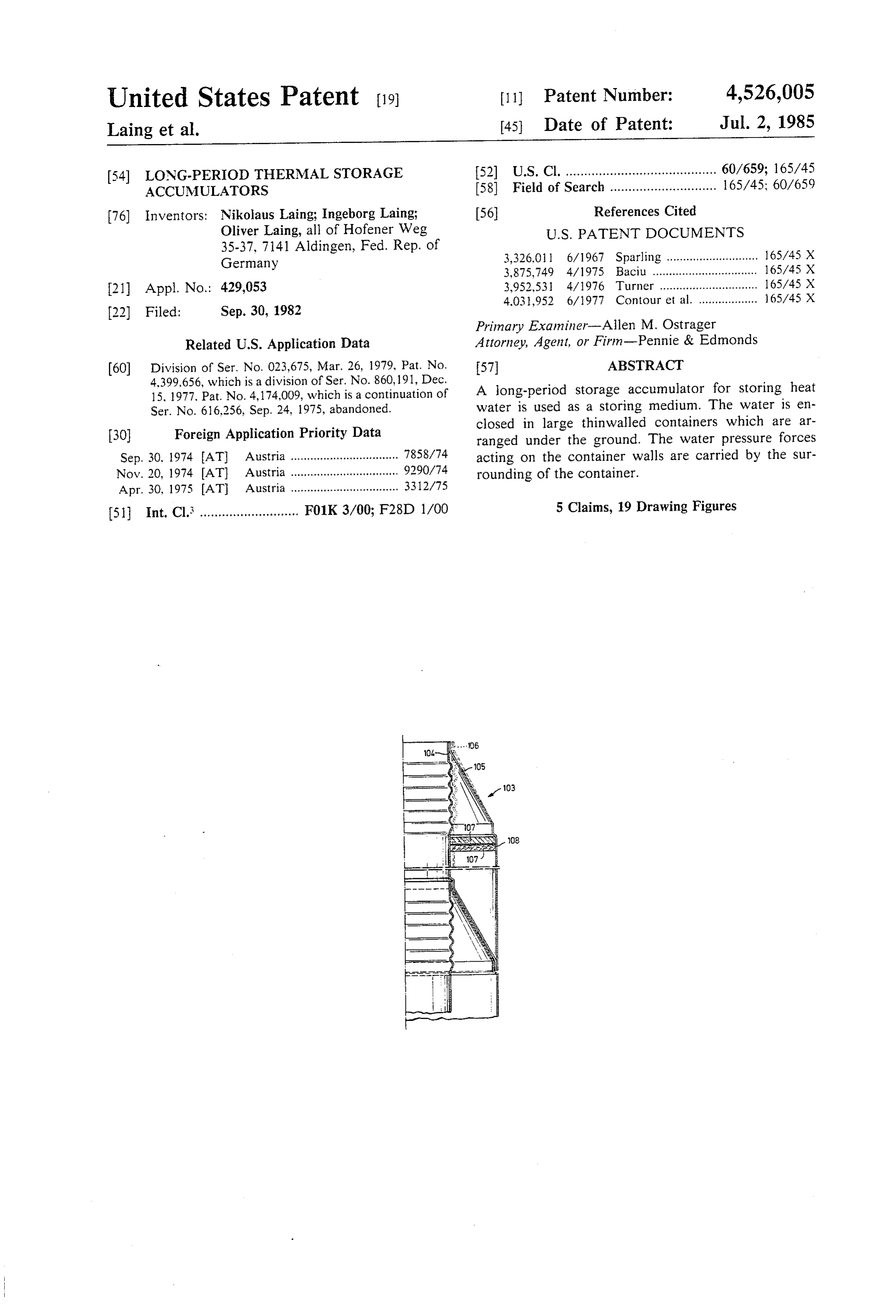
Page 2
Drawing sheet — no readable text.
Page 3
Drawing sheet — no readable text.
Page 4
Drawing sheet — no readable text.
Page 5
Drawing sheet — no readable text.
Page 6
Drawing sheet — no readable text.
Page 7
Drawing sheet — no readable text.
Page 8
Drawing sheet — no readable text.
Page 9
Drawing sheet — no readable text.
Page 10
Drawing sheet — no readable text.
Page 11
Drawing sheet — no readable text.
Page 12
Drawing sheet — no readable text.
Page 13
Drawing sheet — no readable text.
Page 14
LONG-PERIOD THERMAL STORAGE 1. Description of a Heat Sink Storage Accumulator ACCUMULATORS The efficiency and power output of a power station can be enhanced in making use of the invention by
REFERENCE TO OTHER APPLICATIONS 5 widening the operating temperature drop during peak This application is a division of our co-pending appli load periods with the help of heat sink storage accumu cation Ser. No. 023,675 filed Mar. 26, 1979 now U.S. lators. A cavern is created by salt-solution mining in a Pat. No. 4,399,656 which in turn was a division of appli salt rock formation, the volume of which should cation Ser. No. 860,191 filed Dec. 15, 1977, now U.S. amount to 1000 m3 per MW of electrical output power Pat. No. 4,174,009, which in turn was a continuation of 10 of the power station. A saturated water-NaCL solution application Ser. No. 616,256 filed Sept. 24, 1975, now is contained in the storage accumulator, which serves as abandoned. the storage medium. During part-load periods, the ma
THE PRIOR ART
chine set of the power station drives a refrigeration
compressor which compresses a refrigerant, preferably
Thermal storage accumulators based on the heating an aliphatic hydrocarbon.
of water are known. They have not been used industri The refrigerant is then condensed in a condenser by a ally as long-period accumulators because the invest throughflow of e.g. river water and thereupon fed in the ment into the storage containers, determined by the liquid state via a throttle valve into the cavern accumu required container volumes and internal pressures, 20 lator. Evaporation of the refrigerant proceeds in the makes economic operation impossible. The weight of accumulator with simultaneous crystallisation of the steel for a thermal storage accumulator with a one week storage medium. A peak load, the steam discharged capacity in a nuclear power station is larger than the from the power station turbine is fed into a condenser, weight of the water to be stored in it. Long-period in which a hydrocarbon, e.g. propane, evaporates. This storage accumulators are defined as accumulators 25 vapour is fed to a low-temperature turbine, the power which permit as nearly as possible fullload operation of output of which contributes to supply the peak load the steam generator during entire weekends and/or demand. The condensation of the propane vapour takes waste heat utilistaion with a time shift of weeks or even place in a condenser, which is arranged in the storage months. accumulator. During the periods of peak load, the 30 power station operates as a two-component turbine
THE OBJECT OF THE INVENTION circuit system. The temperature drop is increased by the One object of the invention is an improvement in the amount between --35 C. and -21 C. The efficiency utilisation of primary energy, particularly in nuclear of the power station increases from 33% to 42%. The power stations, by means of thermal storage accumula power output of the plant rises thereby from 1,000 MW tors which are charged with excess primary heat and/or 35 to 1,260 MW. A network for the supply of refrigeration waste heat and held in readiness over prolonged peri plants can also be fed from the same storage accumula ods. A further object of the invention is a storage sys tor, using the excess power of the power station during tem and storage accumulators with containers, the low-load periods.
stresses in which are not carried by the container mate 2. Description of a Hot Water Storage Accumulator in rial but by soil or water. In this way, sufficiently large 40 a Cavern containers can be made economically.
DESCRIPTION OF THE INVENTION
Nuclear power reactors usually generate steam. The feed water extracted from the condenser is heated to
According to the invention, caverns in the ground or, near boiling temperature by tapped steam extracted for containers placed under water, external water pres 45 from the turbine. The steam enthalpy amounts to 2,000 sure is used to take up and the pressure of the storage kJ/kg, whilst the usable enthalpy of the feed water is medium. This invention can be used for various storage about 1,235 kJ/kg. The power generation capacity of a media and storage temperatures. turbine plant can become substantially larger if the Three embodiment options according to the inven 50 tapped steam, which withdraws almost half the en tion will be described: thalpy, is not extracted from the turbine but flows 1, Heat sink storage accumulator for condensers of through all the turbine stages and produces work. power stations and/or district refrigeration systems. According to the invention, during low-load periods, 2. Hot water storage accumulator under pressure the excess thermal energy is used, via the tapped steam enclosed in a cavern for the supply of power stations 55 or by direct extraction from the circulation, for heating and/or district heating systems with heat energy. a storage water reserve placed in an underground cav 3. Storage accumulators under pressure placed be ern. The storage water thereby reaches near boiling neath the water level of a natural or artificial water temperature. In peak-load operation, the heat of the basin for the supply of power stations and/or district water, if necessary by the interposition of a heat ex heating systems with heat energy. 60 changer, is drawn on for pre-heating the reactor feed The claimed storage accumulators can also be used to water, so that, during this condition of peration, no advantage in combination and, furthermore, individual tapped steam is extracted from the turbines, whereby distinguishing features of the invention can be used the turbines become capable of producing about 30% outside the field of long-period storage accumulators. In more power output. The depth of the storage accumula the exposition below, specific materials and values of 65 tor cavern is so chosen that the boiling pressure can quantities are given for the sole purpose of facilitating carry the rock cylinder lying above the accumulator, so understanding and should be regarded as examples that the substantial pressure forces are fully absorbed by only. the rock.
Page 15
3. Description of the Underwater Storage Accumulator normal operation and in low-load of electrical power output. In operation, the con
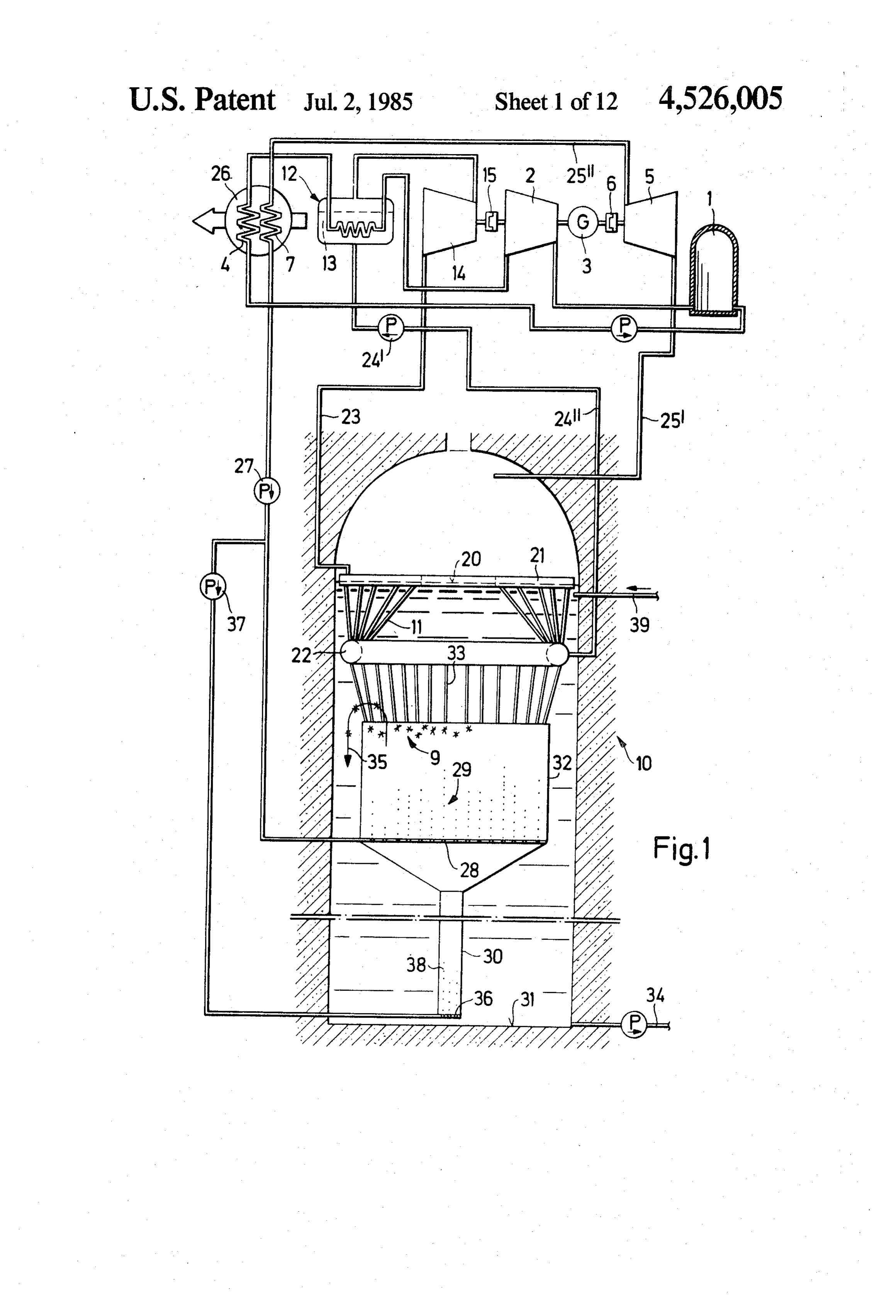
If lakes are available or if the power station is situated densation takesplace in the condenser 4 at a mean tem near the sea, the invention provides the arrangement of perature of about 35 C. In low-load operation, the a storage accumulator at a depth below the water sur 5 refrigeration compressor 5 is engaged by the clutch 6. face such that, at the foot of the accumulator, the pres This compressor withdraws a mechanical power output sure forces of the enclosed storage water are preferably of up to 230 MW from the common shaft and draws in balanced by the external water pressure. In this way, it gaseous refrigerant from the upper region of the storage is possible to use plastic foils as storage accumulator accumulator via the pipeline 25. The heat of condensa walls. Since the hot water of lower specific weight lies O tion of the refrigerant is transferred via the pipeline 25' underneath the sea water of higher specific weight, the in the condenser 7 to the cooling water, which is still top cover forms an unstable membrane. For this reason, cold. The evaporation of the refrigerant takes place a membrane of a specific weight exceeding 1 g/cm3 is after its discharge through the orifice plate 28. Eutectric chosen. crystals 9 are produced by the evaporation. Since these Insofar as gas is used for insulation, according to the 15 are somewhat lighter than the saturated aequeous salt invention, this gas is compressed to the same pressure as solution, they first wander upwards and subsequently the outside and the inside media. However, the inven along the arrow 35 until the entire storage accumulator tion also provides for the thermal insulation to be ac is filled with crystals. A condenser 11 is situated in the complished by the water itself. Thus water contains upper region of the storage accumulator 10. At peak according to the invention may remain open down 20 load, the condensation of the discharged steam takes wards, i.e. without additional insulation. Towards the place in the evaporator 12 which is filled with propane walls and the ceiling, a structure is inserted near the 13. The propane inner wall surface which prevents convection of the turbine 14 whichvapour so formed drives the secondary supplies up to 130 MW to the genera water layers adjacent to the wall so that the water pene tor trating this structure acts as an insulator. For the opti 25 are 3available via the coupling 15. In this way, up to 1,130 MW for electrical power generation during the mum matching of the temperature prevailing inside the peak-load period.
accumulator and diminishing in the downward direc tion depends on theThe duration of the peak-load opera tion to the temperatures of the water flows to be fed in Sor 5 and on the size power of the of the refrigeration compres latent heat storage accumula or extracted, the invention provides tubes or hoses with tor 10. For an accumulator of one week's capacity, a apertures which can be adjusted in height. 30
The invention will be described below together with lator needs a volume of 1.82. 106 m3. Such an accumu latent energy of 4.6-101 kJ is required.
individual elements according to the invention.
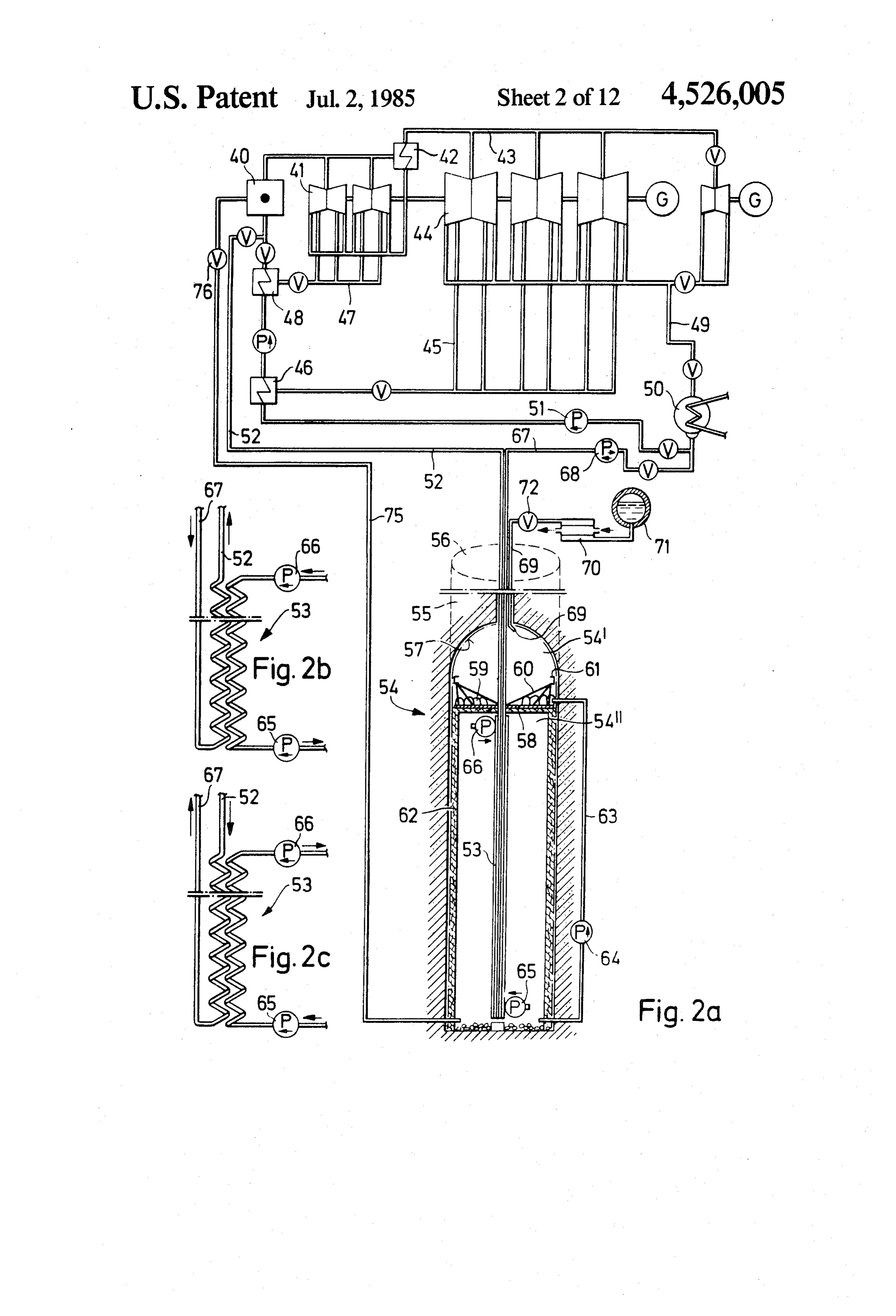
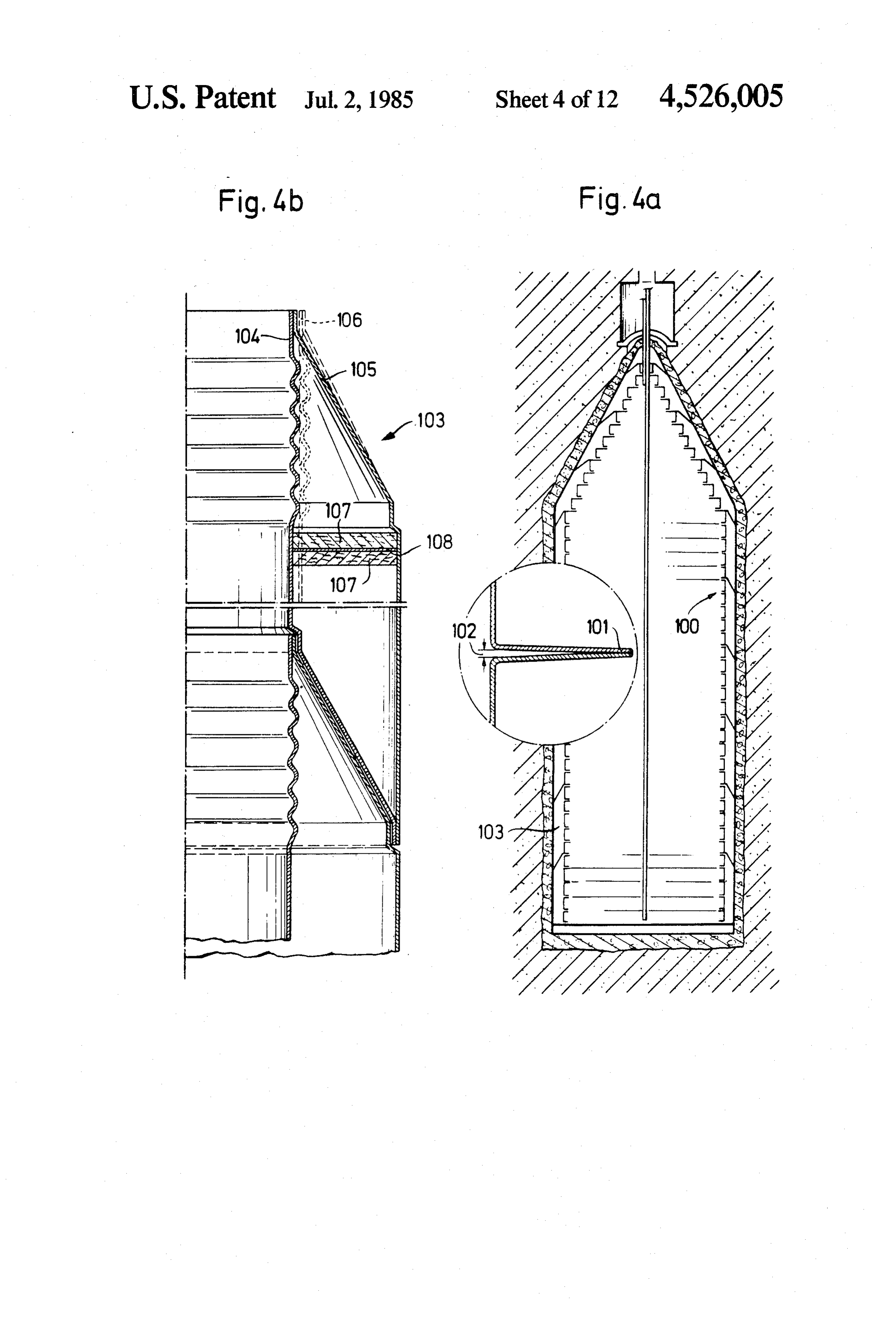
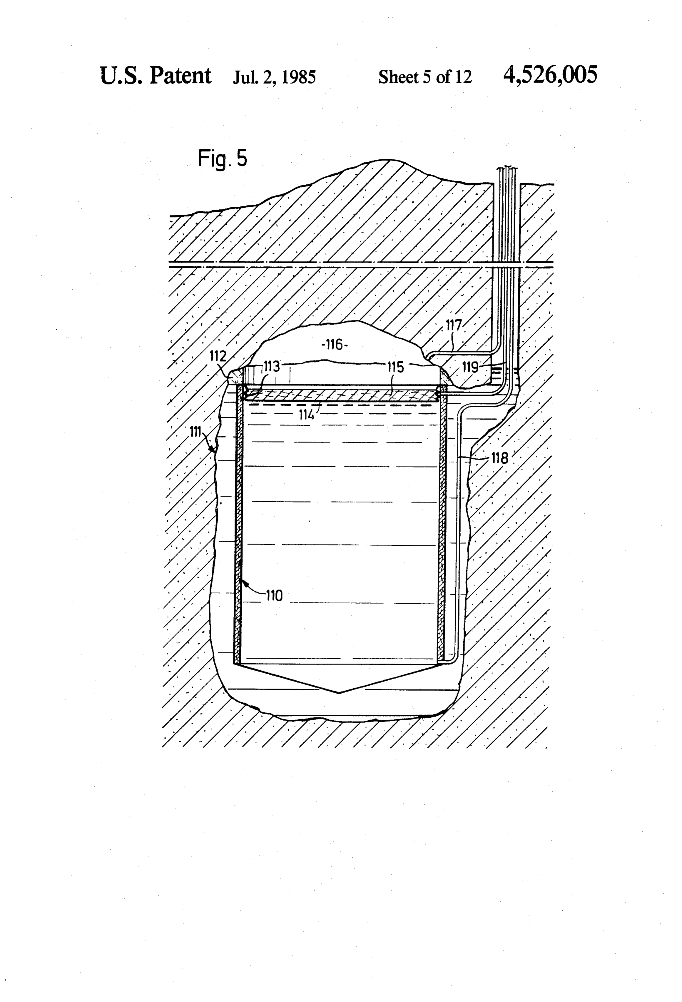
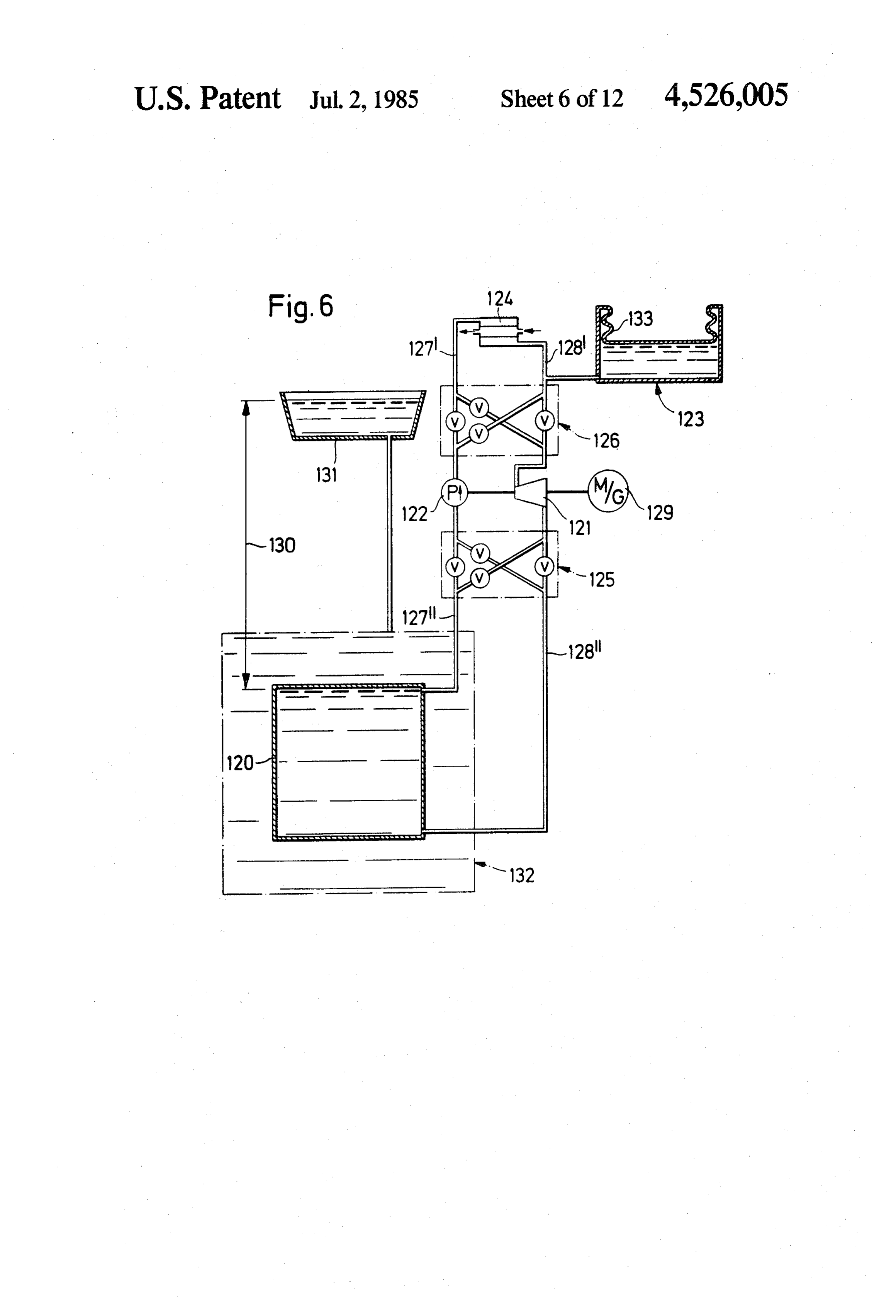
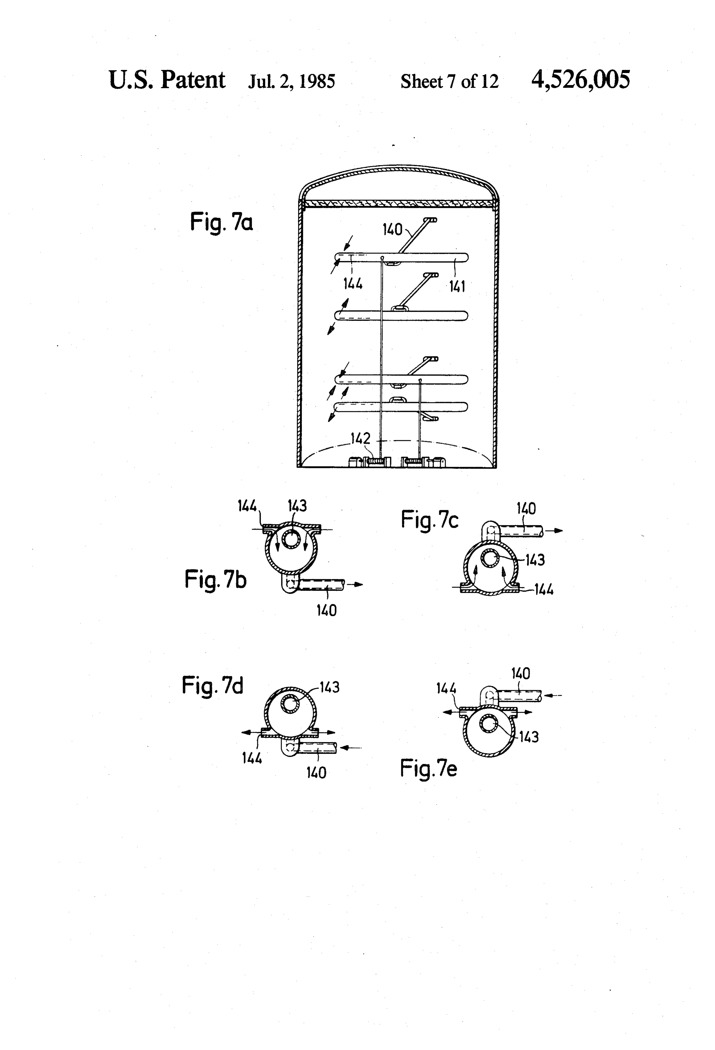
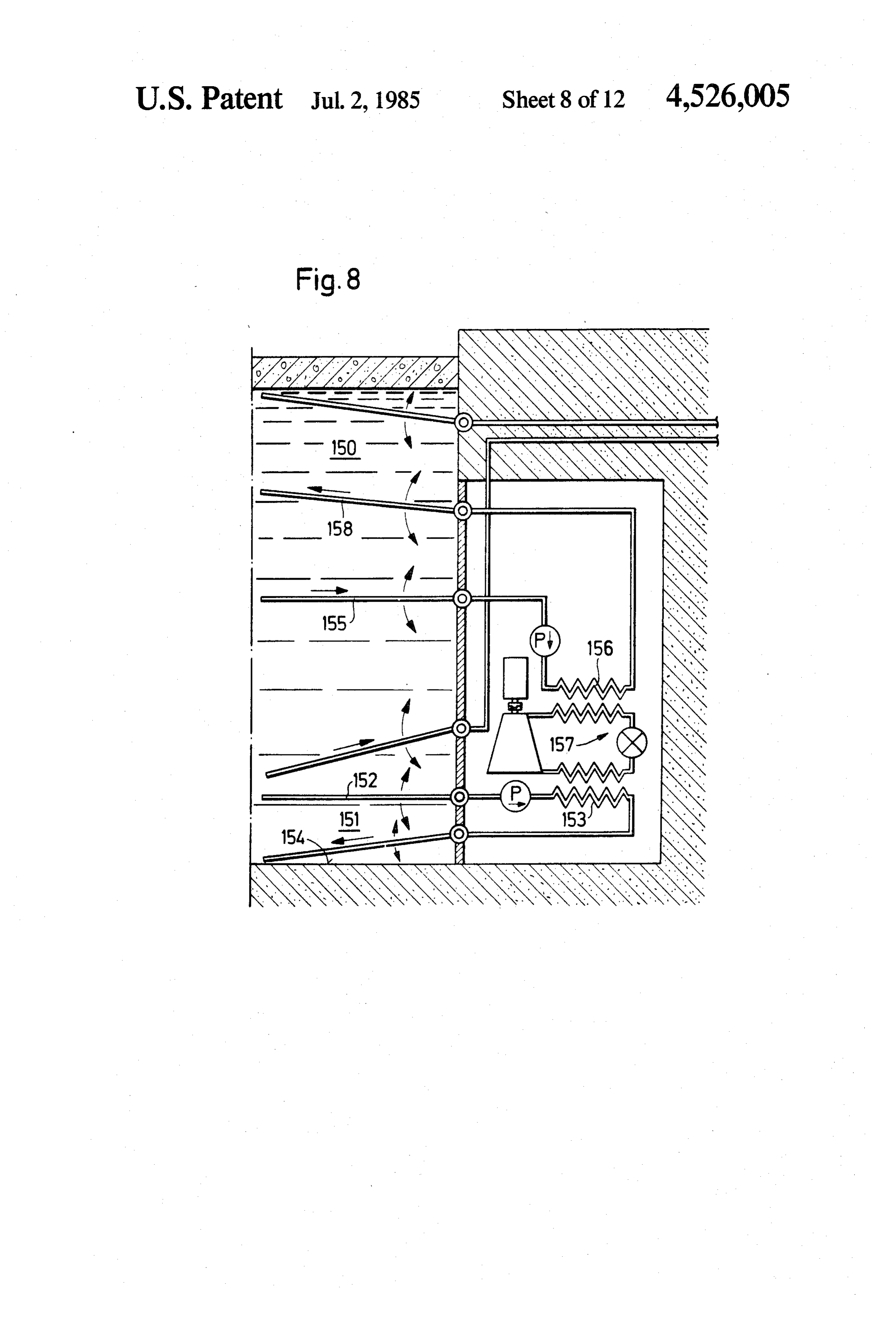
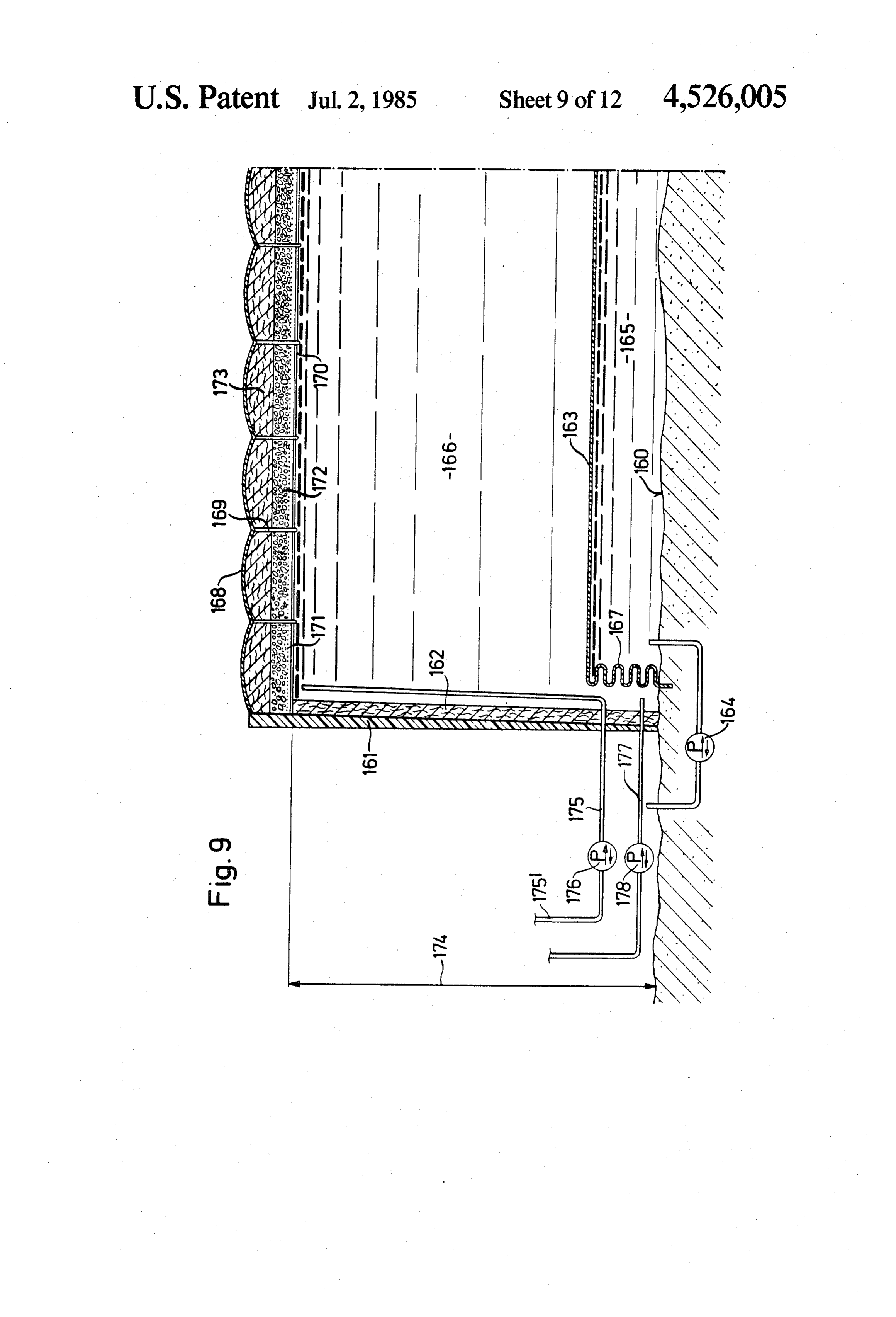
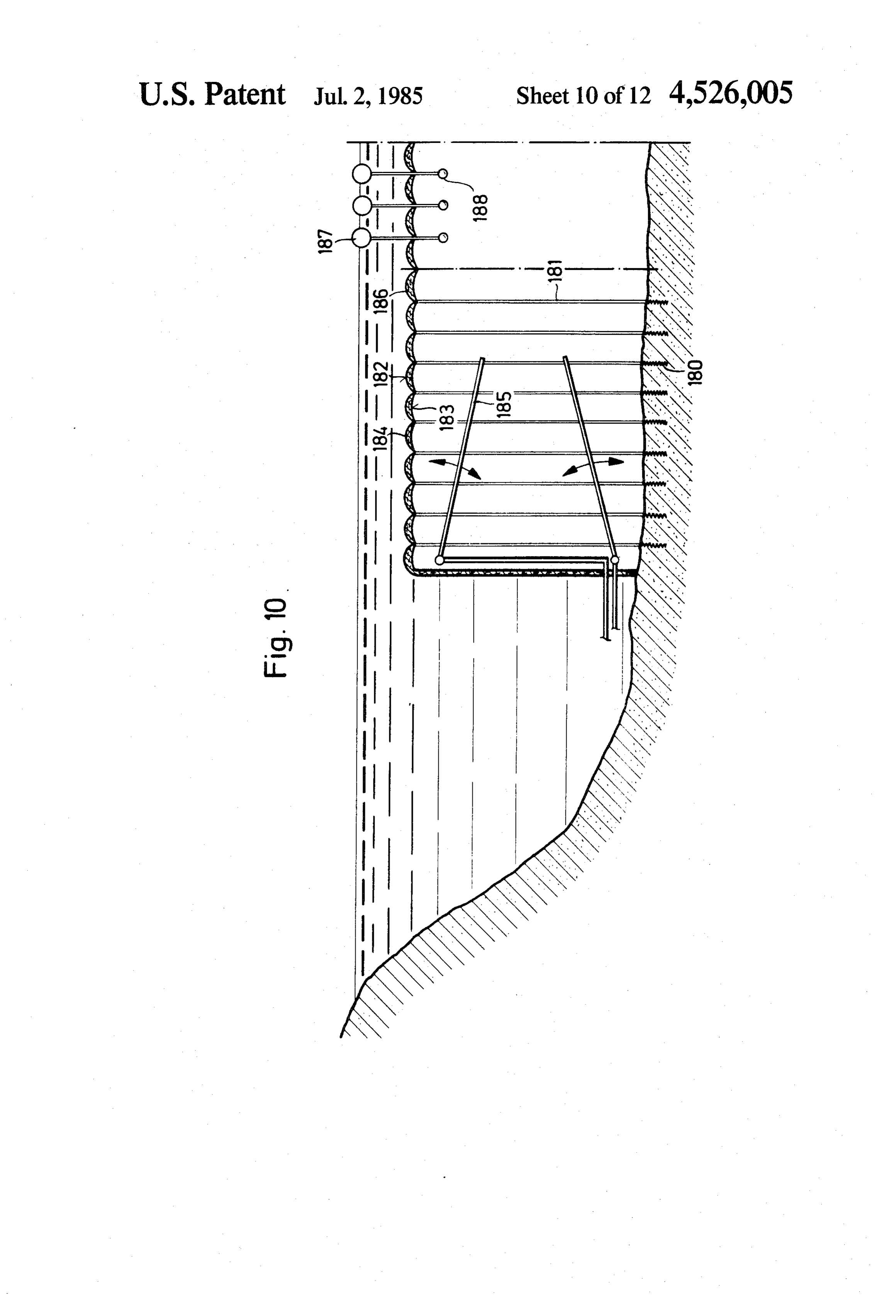
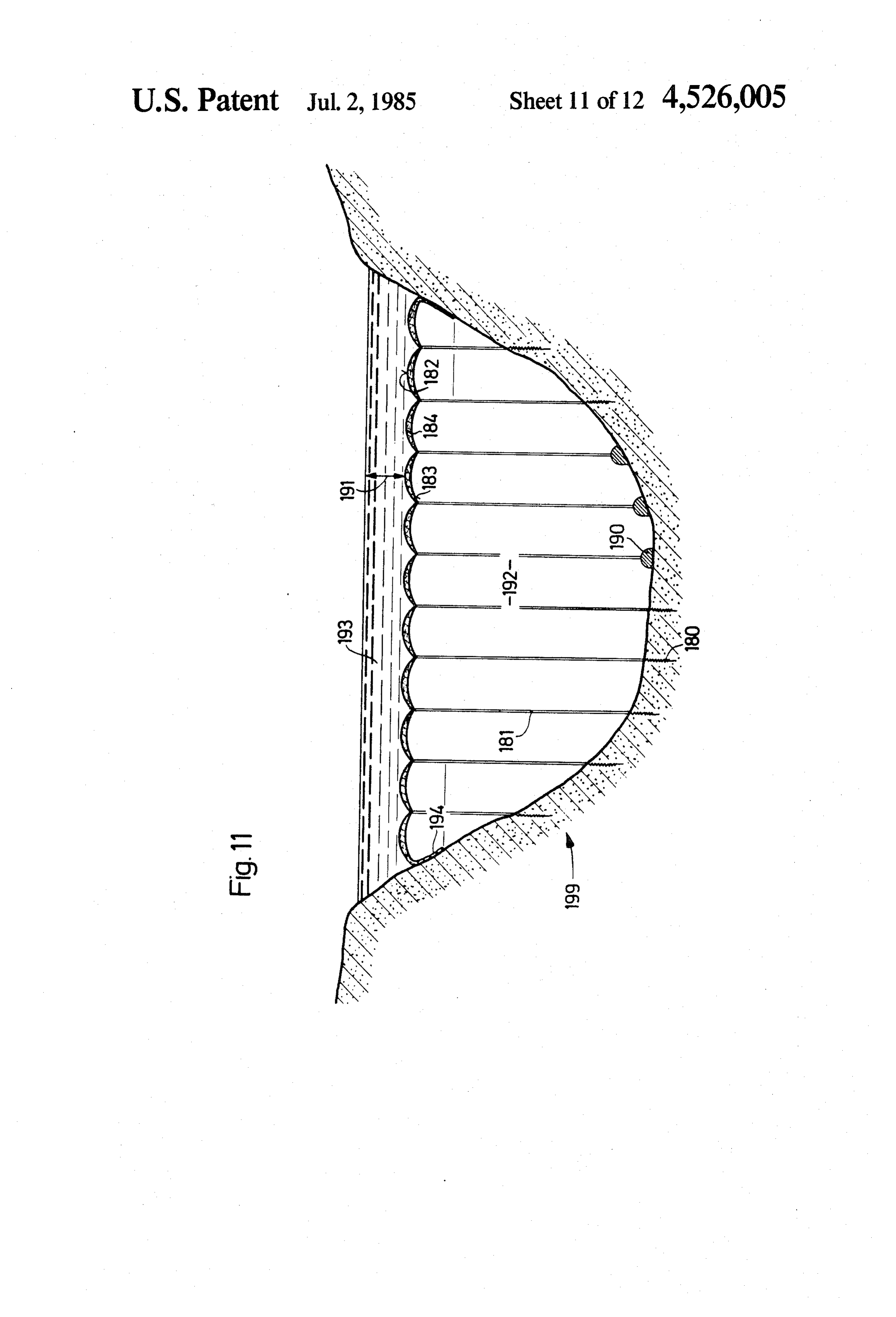
FIG. 1 shows an energy sink storage accumulator An annular hollow body 21 floats on the level 20 of according to the invention together with a power sta the storage substance. The hollow body forms the steam tion. 35 side collector manifold for the plastic condenser tubes FIG. 2a shows a hot water storage accumulator to tube 11. These tubes open out into a weighed-down annular gether with a power station. 22. The collector 21 communicates with the dis FIGS. 2b and 2c show the flow direction during dis charge side of the tubine 14 via the pipeline 23. The charging and charging of the accumulator of FIG. 2a. pipeline 23 may also be connected to a distributor plate FIG. 3 shows an internally situated insulation. 40 similar to the orifice plate 28 instead of a closed con FIG. 4b shows a storage accumulator with externally denser 21, 11, 22, so that the condensation of the dis situated insulation. charged steam takes place in the upper regions of the FIG. 4a shows an insulating element used in the stor accumulator contents, and the condensate collects age accumulator of FIG. 4b. above the level 20 so as to be fed back into the circuit FIG. 5 shows a storage accumulator with a flooded 45 via the pipeline 24" and the pump 24. The compressed Cave. refrigerant flows through the pipeline 25' into the con FIG. 6 shows pumps and turbines to overcome pres denser 26 and from there, via a condensate pump 27, Sure discontinuities. into the orifice plate 28. When the compresser is in FIG. 7a shows tubes with apertures adjustable in operation, refrigerant condensate 29 enters there into height. 50 the brine which is pumped up via the central tube 30 FIGS. 7b-7e show various float designs used in FIG. from the accumulator bottom 31.
7a. A. eutectric brine/ice dispersion forms in the foil FIG. 8 shows an accumulator for storage in layers cylinder 32 which is braced against the annular collec with equipment for increasing the temperature differ tor tube 22 by ropes 33. This dispersion is displaced by ence between the layers. 55 the brine flowing outward along the arrow 35. An ori FIG. 9 shows a storage accumulator for undersea fice plate 36 is arranged in the lower region of the tube installation. 30 in order to convey the brine. A small partial flow of FIG. 10 shows a storage accumulator for undersea the refrigerant condensate, which is pumped by the installation, especially for low temperatures. pump 37, emerges through the orifice plate. In this way, FIG. 11 shows a lake as a storage accumulator. 60 an emulsion 38 is formed in the tube 30. Owing to its 1 FIG. 12 shows a power station plant with a waste w densitiy, the emulsion rises. The maximum energy heat storage accumulator. sink capacity is reached when the entire volume of the FIG. 1 shows the circuit diagram of a storage accu accumulator is filled with the brine/ice dispersion, mulator and power station components. The reactor 1 wherein the proportion of the brine is allowed to dinin generates permanently a thermal power output of 2,380 65 ish down to 20%.
MW. The steam turbine 2 generates permanently a The construction of the storage accumulator takes mechanical power output of a little over 1,000 MW, place preferably in salt rock by solution mining with which, in normal operation, is converted by the genera water. No lining of the cavern is required because a
Page 16
saturated acqueous salt solution is formed whereby a For this purpose, the pump 66 extracts hot water further dissolution of the salt rock is prevented, from the highest level of the accumulator space 54". The storage accumulator thus forms an energy sink, After transferring the heat to the feed water, the hot which leads to an increase of the temperature drop water flows through the pump 65 back into the accumu between the generator 1 and the storage accumulator, 5 lator space.
which serves as a condenser during peak-load opera An aliphatic hydrocarbon is preferably used as a gas tion. A peak-load is thereby provided by the turbine 14. cushion. The temperature in the liquid gas accumulator During low-load operation, on the other hand, the com 71 is so chosen that it lies below the critical temperature pressor 5 is driven. of the gas. The valve 72 prevents the condensation of Refrigeration brine may be additionally extracted 10 the entire gas quantity.
through the pipeline 34 for a supply network to refriger The size of the reserve in the accumulator 71 is so ation plants. The brine throughput flows through the chosen that the entire space 54 can be filled with gas at pipeline 39 back into the storage accumulator. the boiling pressure of the storage water. A pipeline 75 FIG. 2a shows a hot water storage accumulator. The 15 leads from the lower region of the storage accumulator steam generator 40 supplies the high-pressure turbine 41 to the core of the reactor 40. In case of emergency, the and the intermediate superheater 42 with fresh stream. portion within the accumulator which is below 100 The superheated steam proceeds via the pipeline 43 into may be used, via the valve 76, for emergency cooling the low-pressure turbine 44. From there, tapped steam even without pump operation.
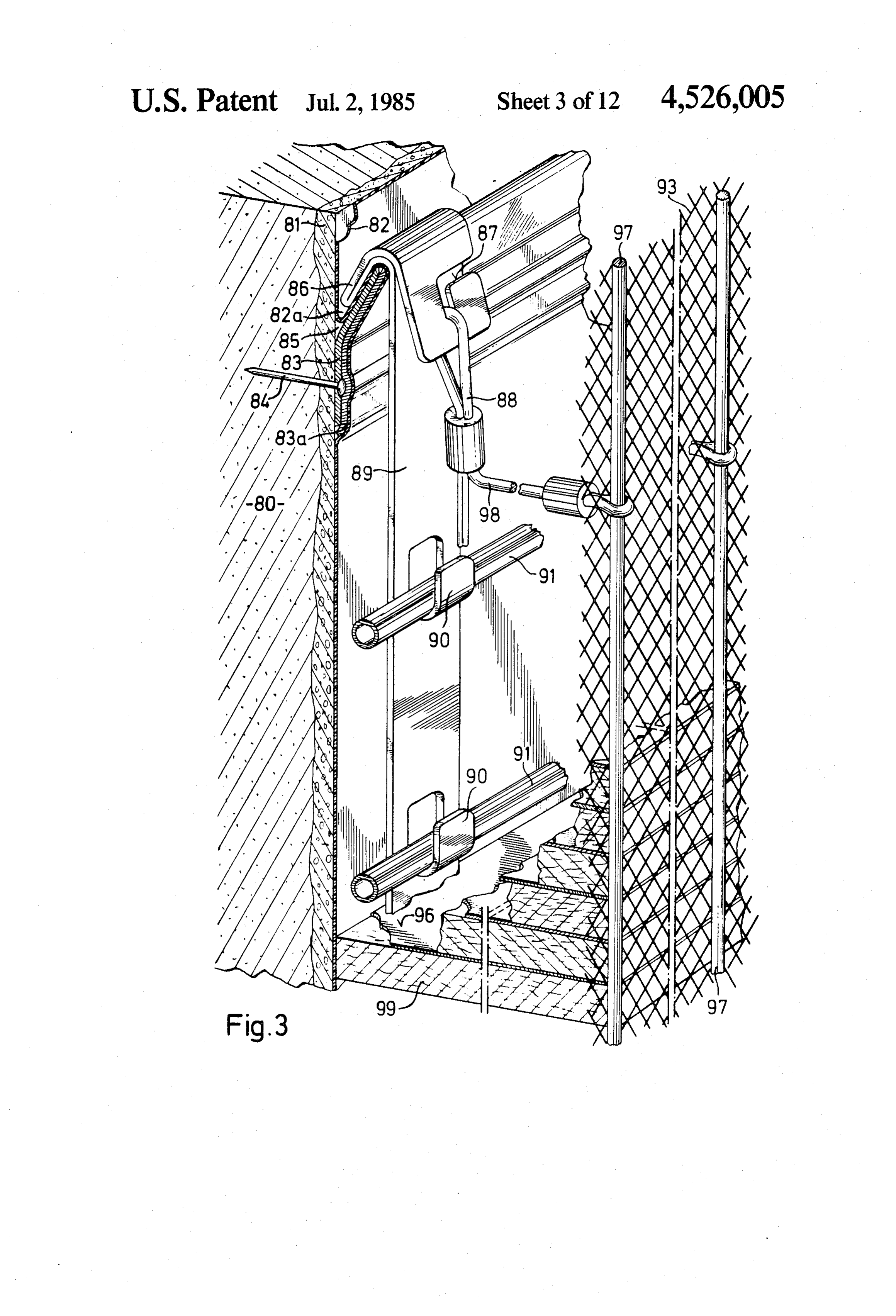
flows through the pipeline 45 into the feed water pre FIG. 3 shows the wall lining of the storage accumula heater 46. High-temperature tapped steam enters via the 20 tor according to FIG. 2. A smooth rendering 81 is ap pipeline 47 into the high-temperature pre-heater 48 so plied to the rock 80. A plastic foil 82 closely fits this that the feed water reaches the evaporator 40 at near rendering. At specified distances, metal profiles 83 boiling temperature. The discharged steam flow formed as horizontal hoops are arranged and fastened to reaches the condenser 50 via the pipeline 49, whilst the the rock 80 by steel nails 84. The web 83a of the metal condensate flows through the boiler feed pump 51 into 25 profile 83 is folded back and covers the heads of the the pre-heater 46. nails 84. Undercut regions 85 are formed between the By opening the valve in the pipeline 52, hot water profile 83 and the wall 81, in which a fold of the plastic enters the heat exchanger 53 of the cavern storage accu foil 82 and metal hooks 86 are inserted. Recesses 87 are mulator 54. The accumulator is placed at such a depth cut in these hooks for suspending the tension cables 88. that the rock column 55 has a weight equal to the pro 30 Clips 90 are stamped out in the lower web 89 of the jected area 56 multiplied by the internal pressure in the hook components, in which coolant tubes 91 are in accumulator 54. serted. The foil 82 is thus made into a fold 82a in the The accumulator wall consists of a plastic foil 57. The accumulator space is sub-divided by an intermediate region 81 of the hooks and is fastened to the rock wall 80, without being perforated by nails. The insulation plate 58 into two regions 54 and 54". This intermediate 35 consists of layers plate is weighed down by weights 59 and, if necessary, with a wire netting9993,which These are covered on the inside wire nets 93 are held in braced into a flat shape by ropes 60 which are carried by position by rods 97 and ropes 98. tension fittings 61. The region 54" is lined with an insu rial 99 consists of hydraulically andThe insulating mate thermally resistant lating layer 52. The pipeline 63 with the pump 64 is minerai fibres or else of metai fibres, coal powder or situated between the two regions 54 and 54'. 40 coke and is permeable to water, whilst it prevents
The heat exchanger is traversed either by a flow of mal convection and the mixing of water layers near the ther cold water (during charging) from the pump 65 or by a wall flow of hot water (during discharging) from the pump tainedso between that a temperature drop of up to 300° C. is sus the wire netting 93 and the cooling 66. In order to discharge the accumulator, the hot water water tubes 91. Foils traverses the heat exchanger 53 and thereby heats the between the layers of96,thee.g.
feed water flowing through the heat exchanger, as vent vertical convection. insulation 99. These foils pre shown in FIG. 2b. The heat exchanger separates the are traversed by cold water which is at water The cooling the pipes 91 same pres turbine circulation from the storage accumulater circu sure as the water enclosed within the accumulator so lation so that the hydrostatic pressure, if it exceeds the that, inside the insulating layer, a temperature gradient boiling pressure in the pipelines 52 and 67, does not act 50 prevails between the accumulator water temperature on the accumulator walls.
When charging the cooled water returns into the and the cooling water temperature and the foil 82 can turbine circulation via the pipeline 67 by the interposi never assume excessively high temperatures. FIG. 4a shows another design of the storage accumu tion of the pump 68, whilst the pump 65 pumps cold lator. The accumulator container proper 100 consists of accumulator water through the heat exchanger 53. The 55 cold accumulator water, after being heated up, dis steel rings made of U-profiles, the flanges of which are charges through the inoperative pump 66 (FIG.2c). welded together as shown at 101, whilst the vertical During the charging process, the water in the space webs leave gaps 102 between each two profiles, 54' expands. A corresponding quantity of cold water is whereby the longitudinal expansion can be absorbed. pumped by the pump 64 into the space 54". A pipeline 69 60 Thements insulation is provided by hollow insulating ele
communicates with the space 54" and also, via the heat FIG. 4b shows the design of such a hollow insulating exchanger 70, with an insulated liquid gas accumulator 71. element 103. The wall 104, facing the accumulator con The circuit diagram for discharging the accumulator tainer, has corrugations which absorb the longitudinal is also shown in FIG. 2b. The cold boiler feed water is 65 expansion. The conical wall 105 can yield according to pumped by the pump 68 via the pipeline 67 into the heat the broken line illustrated at 106 when the accumulator exchanger 53 and fed via the pipeline 52 in a hot condi container 100 increases in its diameter. Mineral wool tion to the evaporator 40, slabs 107 are placed inside the annulus, between which
Page 17
intermediate layers 108 are situated to prevent convec FIG. 8 shows a circuit diagram which serves for the tion. optimisation of the temperature gradient inside the stor FIG. 5 shows a storage accumulator according to the age accumulator. The pipe 152 extracts water from the invention which is arranged to float in a cavern. The cold region 151 and cools this water in the heat ex accumulator container 110, the wall of which is insu changer 153 so that even colder water emerges at the lated either by internal insulation, as shown in FIG. 3, bottom 154, whilst the pipe 155 extracts warm water or by external insulation, as shown in FIGS. 4a and 4b, from the upper region, heats it up in the heat exchanger floats in the flooded cavern 111. The accumulator wall 156 of the heat pump 157 and returns this water through is anchored to a supporting ring 112. An annular bel the pipe 158, situated at a greater height, into the hotter lows-type component 113 is joined to the supporting O region 150.
ring. The bellows component carries the cover 114. FIG. 9, which is not to scale, shows an accumulator This cover is overlaid with an insulating layer 115. according to the invention, which is arranged at the Compressed gas or liquid under pressure is injected bottom of the Sea 160. The outer wall 161 is formed as through a pipeline 117 into the space 116 above the a body of revolution and increases upwards in its wall cover. The cold water and hot water pipelines 118, 119 15 thickness because it has to resist the internal pressure are connected to pumps or turbines, respectively. The which increases in the upward direction. According to cold water pipeline also communicates with an expan the invention, this wall consists preferably of strips sion tank 131 (FIG. 6). made of glass fibre reinforced synthetic material and has According to the invention, the inside of the cavern on its interior wall an isolating layer 162. 111 can also be filled with compressed air or nitrogen. 20 The space 165 serves as an expansion chamber for the In all cases, the storage accumulator can also be placed changing density of the water enclosed in the storage inside a mountain, where the shaft may be horizontal, accumulator space 166. Alternatively, the accumulator tOO. can be operated at constant mass. However, the en FIG. 6 shows diagrammatically an arrangement ac closed storage water can also be extracted. This proce cording to the invention. The accumulator container 25 dure depends on the expansion bellows portion 167 of 120 communicattes, via a turbine 121 and a pump 122, the foil 163 having approximately the dimensions of the with an expansion container 123 covered by a mem wall 161.
brane 133 and with the heat exchanger 124. The valve The cover of the accumulator container consists of an batteries 125 and 126 are so controlled during discharge outside wall 168 which is preferably made of plastic foil. that the hot water pipelines 127 and 127" are connected Tension ropes 169 are attached to this wall which carry via the turbine 121, whilst the cold water pipelines 128 a steel wire net 170. The steel wire net is panelled with and 128' are connected via the pump 122. a fine-mesh wire gauze 171.
Since the density of the cold water is greater than that A layer 172 of sand or stones is placed above this net of the hot water, the turbine supplies, even without structure and, above this layer 172, a further layer 173 taking account of efficiencies, less power than is needed 35 of mineral wool. The weight, less the buoyance of the by the pump 122. The power deficiency is balanced by layer 172, must be larger per unit of area than the pres a motor-generator 129. In the reverse flow condition sure difference resulting from the density difference during discharging, the power generated by the turbine between the hot water inside the container and the sea 121 may be larger than the power absorbed by the pump water outside the container, multiplied by the height 122. If so, the motor-generator 129 may be operated in 40 difference 174. If a pressure difference remains, it is a generating mode. The pipelines 127 and 128 are then overcome by the pump 164.
appropriately changed over. In conjunction with suit In charging or discharging, hot water is conducted able automatic control elements, the turbine and pump through the pipeline 175'. The turbine-driven pump 176 achieve a compensation of the hydrostatic column pres overcomes the excess pressure in the pipeline 175' due sure in the pipes 127" and 128 which span the height 45 to the depth position in the sea. The pipeline 177 is difference 130. In this way, the accumulator container relieved by the turbine-driven pump 178. The depth 120 is relieved of hydrostatic pressure. below sea level must be chosen in accordance with the The tank 131 communicates with the inside of the boiling pressure. At 350° C. water temperature, for cavern 132, whereby a pressure forms inside the cavern example, the required depth amounts to about 1,650 m. which results from the height difference 130. 50 FIG. 10 shows a modified arrangement in a lake. If FIG. 7a shows the design of the feeding and extrac the bottom of the lake is accessible, anchors 180 are tion pipelines. Since temperature stratification forms in fixed in the bottom. The covering foil 162 is held in a the accumulator and the need arises to perform feeding horizontal position by ropes 181. A wire netting 183 is and extraction at optimum temperatures, the invention preferably suspended underneath the covering foil. provides the use of tubes 140 which can be adjusted in 55 Mineral wool or, at lower temperatures, an organic height. To prevent turbulence, a float 141 can be ar fibre wool is placed inside the space 184 so formed. ranged at the end of the tube 140 which can be adjusted Tubes 185 with apertures which can be adjusted in to the desired height by means of a winch 142 or by height are situated inside the storage accumulator. changing the gas quantity in a hollow body 143 situated If the lake bottom is marshy, an arrangement shown inside the float 141. 60 on the right is used. The covering foil 186 is weighed FIG. 7b shows the cross-section of the float with a down by weights 188 which are evenly distributed. A float body 143 and the suction apertures 144 situated on float 187 is associated with each weight. The volume of top for the induction of hot water. the floats is larger than that corresponding to the resid FIG. 7c shows the design of the float for the induc ual weight of the bodies 188.
tion of cold water. 65 FIG. 11 shows another arrangement of a storage FIG. 7d shows the float for the discharge of warm accumulator which can be embodied in lakes of which water and and FIG. 7e shows the float for the discharge the total volume is approximately equal to the desired of cold water. accumulator volume. As before, tension anchors 180 or
Page 18
weights 190 are arranged at the bottom 199 of the lake. when the river water is particularly cool or when the A covering 182, 183, 184 is placed at a depth 191, which river flow is particularly large. A corresponding leads to a preliminary pressurisation inside the storage amount of fresh water is returned from the lake into the accumulator 192 to a value higher than the boiling pres storage accumulator via the pipeline 223. sure of the stored water. The upper region 193 remains 5 We claim:
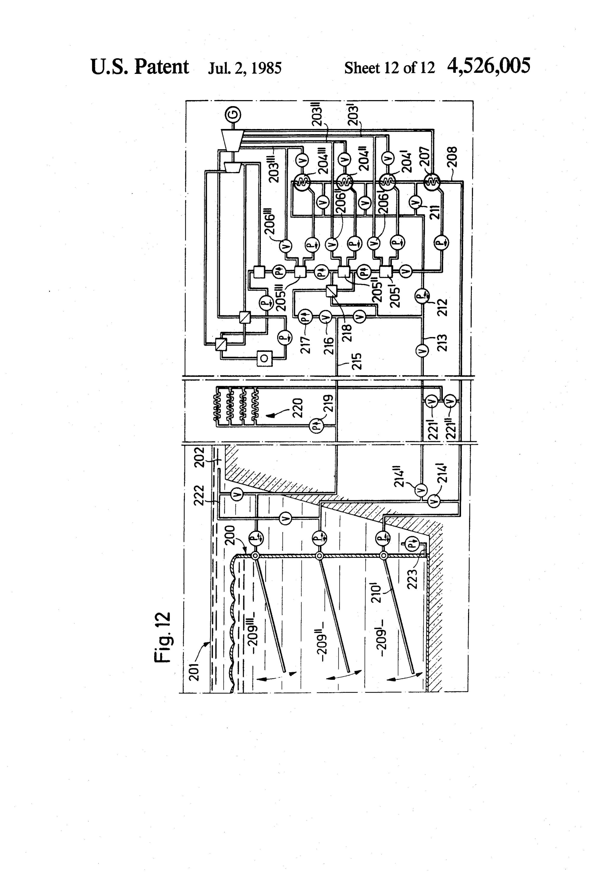
full of cold lake water. Surrounding foil lip 194 which 1. A long-period heat storage accumulator adapted to separate the two water layers from each other are pro contain a large volume of water where the accumulator vided to seal against the rising shores of the lake. is for use with a power station and where the accumula FIG. 12 shows an example of the application of a tor has means for filling and removing water therefrom, low-temperature storage accumulator 200, according to O the improvement comprising in that said accumulator is the invention, which is placed in a lake 201, communi contained with a cavern formed from a rock formation cating with a river 202. The tapped steam pipelines 203, whereby the pressure of the water in the accumulator is 203' and 203' are connected to the condensors 204, contained by the rock formation and in that an accumu 204" and 204". In addition, feed water pre-heaters 205', lator wall is spaced from the rock formation with the 205" and 205" are provided, which, in an appropriate 15 space between the rock formation and the wall being control position of the valves 206", 206' 206", can filled with compressed gas at a pressure equal approxi absorb the tapped steam. The main condenser 207 is mately to the pressure of adjacent hot water. connected, via a pipeline 208, to the lower region 290' 2. A long period heat storage accumulator according of the storage accumulator 200. By swivelling the tubes to claim 1 wherein the space between the wall of the 210", the desired water temperature can be fed in. 20 accumulator and the rock formation is filled with a
During peak-load operation, the cold water, via the saturated vapor of a liquid the critical temperature of main condenser 207, the valve 211, the pump 212 and which lies below the lowest operating temperature of the pipeline 213, reaches the intermediate region 290" of the storage water but above the temperature of a gas the storage accumulator 200. At a sufficiently low accumulator container connected with the interior of power station load, the condensation takes place in one 25 the accumulator.
of the condensers 204. If the condenser temperature is high enough, the cooling water extracted from the re to 3.claim A long period heat storage accumulator according 2 having in addition means for maintaining the gion 209" and fed, via the valve 214", into the pipeline temperature of gas in the gas accumulator at a specified 208, whilst the valve 214" is shut and, after heating up value.
through the pump 212 and the pipeline 215, is conveyed 30 4. A long period heat storage accumulator according into the upper region. 209' of the storage accumulator. to claim 2 wherein said gas is an aliphatic hydrocarbon. In peak-load operation, hot water may, in addition, be 5. A long-period heat storage accumulator adapted to withdrawn from the upper region 209" and supplied, contain via the pipeline 215, the valve 216 and the pump 217, to is for usea with large volume of water where the accumulator a power station and where the accumula the heat exchanger 218 for heating the feed water. In tor has means for
order to withdraw the heat, the pump 219 pumps hot the improvement filling and removing water therefrom, comprising in that said accumulator is water into the district heating network 220. This hot contained within a cavern formed from a rock forma water is returned either into the lower region 209' or the intermediate region 209" by appropriate control of the tion whereby the pressure of the water in the accumula valves 221" and 221'. If the heat extraction by the dis 40 torthe is contained by the rock formation and in that a wall trict heating network 210 is insufficient, feed water is of accumulator comprises a plurality of U-shaped bled from time to time via the pipeline 222 into the river rings with gaps between adjacent rings to absorb longi 202. Out of consideration for the least possible thermal tudinal expansion. ck 2k 2k ck 2k pollution of the river, the bleeding takes place at times
Provenance
- Collection
- Cited prior art
- Original PDF
- patentimages.storage.googleapis.com →
- Filed
- 1982-09-30
- Pages
- 18
- Method
- pdftotext (the PDF's own text layer) + pdftoppm 300dpi page scans
- Source
- Google Patents bibliographic record
- Granted
- 1985-07-02
- Inventors
- Nikolaus Laing; Ingeborg Laing; Oliver Laing
- Transcribed from
- patentimages.storage.googleapis.com →