patent · US4253801
Convection current pumping called, series convection pump
3 March 1981
Page 1 — bibliographic record
United States Patent (19) 11) 4,253,801 O'Hare 45) Mar. 3, 1981 (54) CONVECTION CURRENT PUMPING 4,059,126 11/1977 Nickerson .......................... 417/52 X CALLED, SERIES CONVECTION PUMP Primary Examiner-Albert W. Davis 76 Inventor: Louis R. O'Hare, 1041 Ponderosa Assistant Examiner-Margaret A. Focarino #2, Fort Collins, Colo. 80521 57 ABSTRACT (21) Appl. No.: 805,005 An array of several convection tubes are positioned in a 22 Filed: Jun. 9, 1977 series configuration to provide the equivalent of a very 51) Int. Cli.............................................. F04B 19/24 tall convection current generating tower, the pressure 52 U.S. Cl. ......................................... 417/52; 165/45 and fluid flow of the array thereby becoming capable of 58) Field of Search .................. 417/52, 207; 165/485, significant pressures such as the pressures necessary to 165/45 move solar heated air into the confines of a rock storage 56) References Cited area, the pressure increases of this array being achieved by the additive effects of connecting heated and cooled
1,063,636 6/1913 Barbezat.............................. 417/207 that the output of one is connected to the input of an 3,098,602 7/1963 Torluemke. . 417/207 X other.
3,565,551 2/1971 Hobson ...... 417/207 3,981,627 9/1976 Kantor ................................. 417/207 6 Claims, 7 Drawing Figures
Page 2
Drawing sheet — no readable text.
Page 3
Drawing sheet — no readable text.
Page 4
Drawing sheet — no readable text.
Page 5
Drawing sheet — no readable text.
Page 6
sensibilities would provide pressure and movement
CONVECTION CURRENT PUMPING CALLED, advantages over present passive systems. SERIES CONVECTION PUMP Since passive systems for solar heating can be de signed large enough to be "energy free', in an energy
This invention relates to the art of moving fluids i.e. 5 depleted world a truely suitable convection pump gas or liquid by means of convection. It refers to the would have great merit for saving energy presently heating and/or cooling of certain quantities or volumes required in solar energy circulation. The high convect of gas to produce a temperature differential between ing tower is one such pump which can make the passive that volume and the ambeint temperature of the sur solar system more practicable by adding advantageous rounding fluid in order that a heated and expanded 10 pressures to the passive system.
volume will rise relative to the surrounding gas and in However, there is a way in which the advantages of order that a cooled quantity of gas will fall relative to a high pressure convecting system may be had without the surrounding gas. This art is familiar in the use of the the aesthetically offensive and physically difficult re smoke stack in which the rising heated gases and vapors quirement of constructing a tower. This present inven ascend because of their reduced weight and by ascend 15 tion then particularly specifies several shorter towers or ing draw useful oxygen-rich combustion air into the convecting columns so arranged in a series configura firebed of a furnace. The rising due to a density decrease tion and interconnected that the pressure differential caused by heating or the descending due to a density developed across each adds to provide a total pressure increase is familiar in liquids as well as in gases and as an 20 which is the sum of the pressures developed across each example of the art of moving a fluid for a useful purpose column. This obviously cannot be done by alternately by means of a convection reference can be made to the connecting the top of each heated column to the bottom currents in a boiler in which a rising heated column of each succeeding heated column as there would be draws cooler water into the hotest area for heating. heated fluid in the inter connecting lines. Each pair This present invention, however, differs from the 25 would formed of one inter connecting line and one column prior art not in that it is a novel application of a well umns adjacent actually and effectively equal two heated col known and well used mechanism but in that it comprises oppose each other to each other and their pressures would an innovative adaptation of the convection principle in of zero across the producing a net pressure differential two connected together. However, order to make the application much more effective. when
Specifically, my present invention utilizes multiple con nected alternate heated and cooled columns are con in such a manner that the top of a cooled column vection fluid movers aligned in a series configuration in 30 connects to the top of a heated column and the bottom order to produce an additive effect on the pressure and of that cooled column connects to the bottom of the velocity of the moving fluid and it employs these re next heated column quired pressure and velocity elevations for the move at its top connects to and the that same next heated column succeeding cooled column and ment of heating and cooling fluids to produce a more 35 so on, then the pressure differential across each column effective passive solar heating and cooling system. In short my present invention is a multiple stage convec both hot and cold adds to the total pressure differential of the series. In this way several inter connected short tion pump which adds the pressures of multiple convec columns tion columns in order to produce a final pressure on the one very can high produce the same pressure differential as single column. The single high column circulating fluid which is truely adequate to move the 40 would work whether it were heated above ambient or fluid through solar storage systems, such as rock piles or cooled below ambient. It would create a pressure diff tanks, and through areas from or to which heat must be erntial in either case, only the direction of the differen pumped. This invention is described in my Disclosure tial would change. A tall column of cold air would of Document No. 053274 of Oct. 12, 1976. course have its highest pressure at its lowest end. To understand the present method an analagous but 45 In the series convection pump just described, when in some respects less satisfactory system might first be the alternate heated columns are above ambient and the contemplated. Since present passive solar energy col alternate cooled columns are only near ambient temper lection and distribution systems require no external atures then the cooled columns contribute little to the energy input for air or fluid movement but rely on con total pressure differential of the system but the pressure vection to move the heat transfer fluid to various areas 50 differentials of the heated columns still remain additive and through storage there is a certain reluctance to use to the system. Similarly, when the alternate cooled a purely passive system without designing an entire columns are below ambient surrounding temperatures instalation able to operate on a very low pressure differ and the heated columns are near ambient then the ential. This is because the fluid pressure produced by heated columns contribute little to the total pressure the single column formed by the height of the solar 55 differential of the system while the pressure differentials collector or by the single column formed by the height of the cooled columns are additive.
of the storage area and heated area is very low and this Just as a tower type of convection air pump might be pressure is able to move the heating or cooling fluid in placed into a solar heating or cooling system to substi adequate quantity only when conducting ducts are very tute for an electrically driven air blower so also the large and the impedance to flow through storage is very 60 series convection air pump is placed in any standard or low. To reduce the size requirement on the fluid duct retrofit solar system in the same relative place in the air ing and to reduce the size as well as to reduce the low circuit as the conventional air mover is placed. Again flow-impedance requirement through storage of the the series convection air pump substitutes as an "energy conventional passive solar system, use could be made of free' source of air movement to provide a passive solar a very high heated tower. A high tower like a very tall 65 system.
smoke stack could produce a proportionately higher As the embodiment of the basic inventive concept pressure differential to move the heat transferring fluid. embraces fluids generally, it is clear that configuration Such a convection tower while obtruding on aesthetic of hot and cold series convecting columns may be em
Page 7
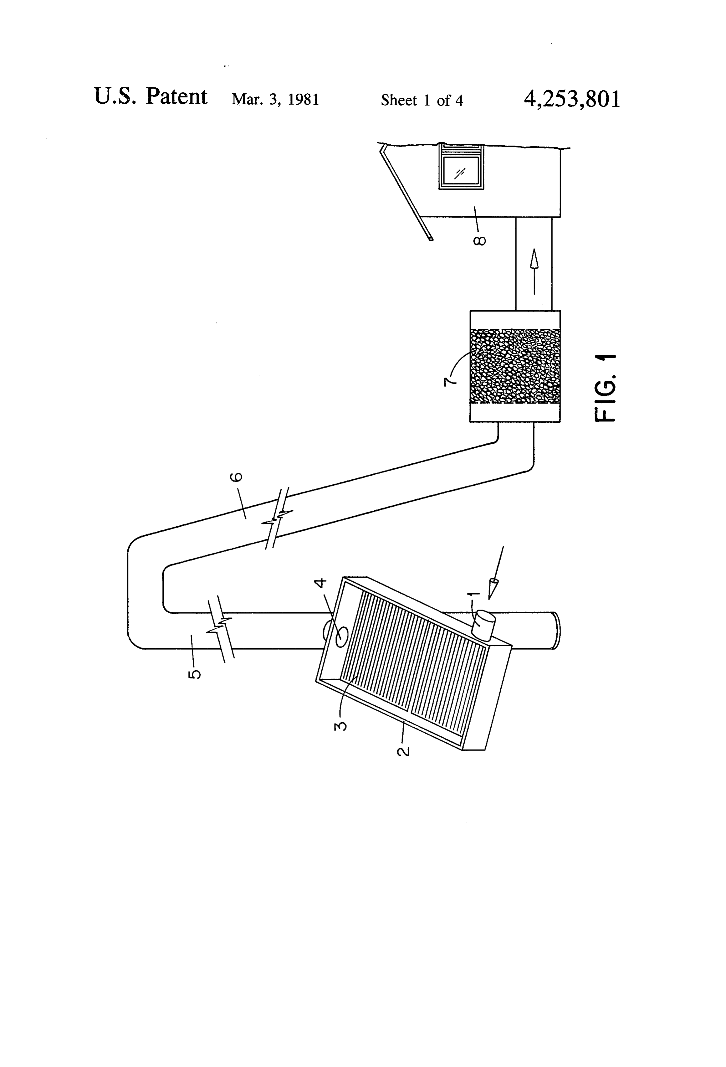
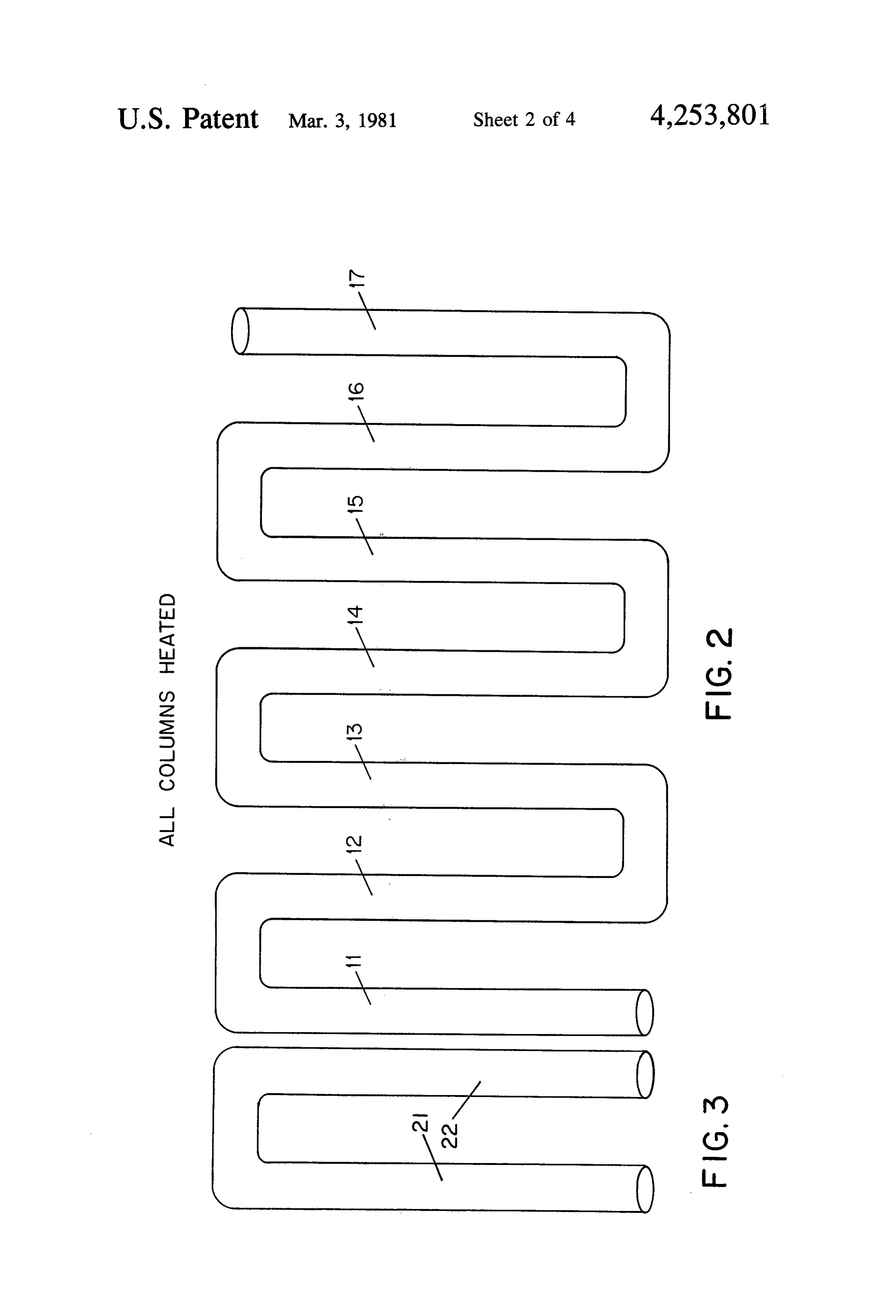
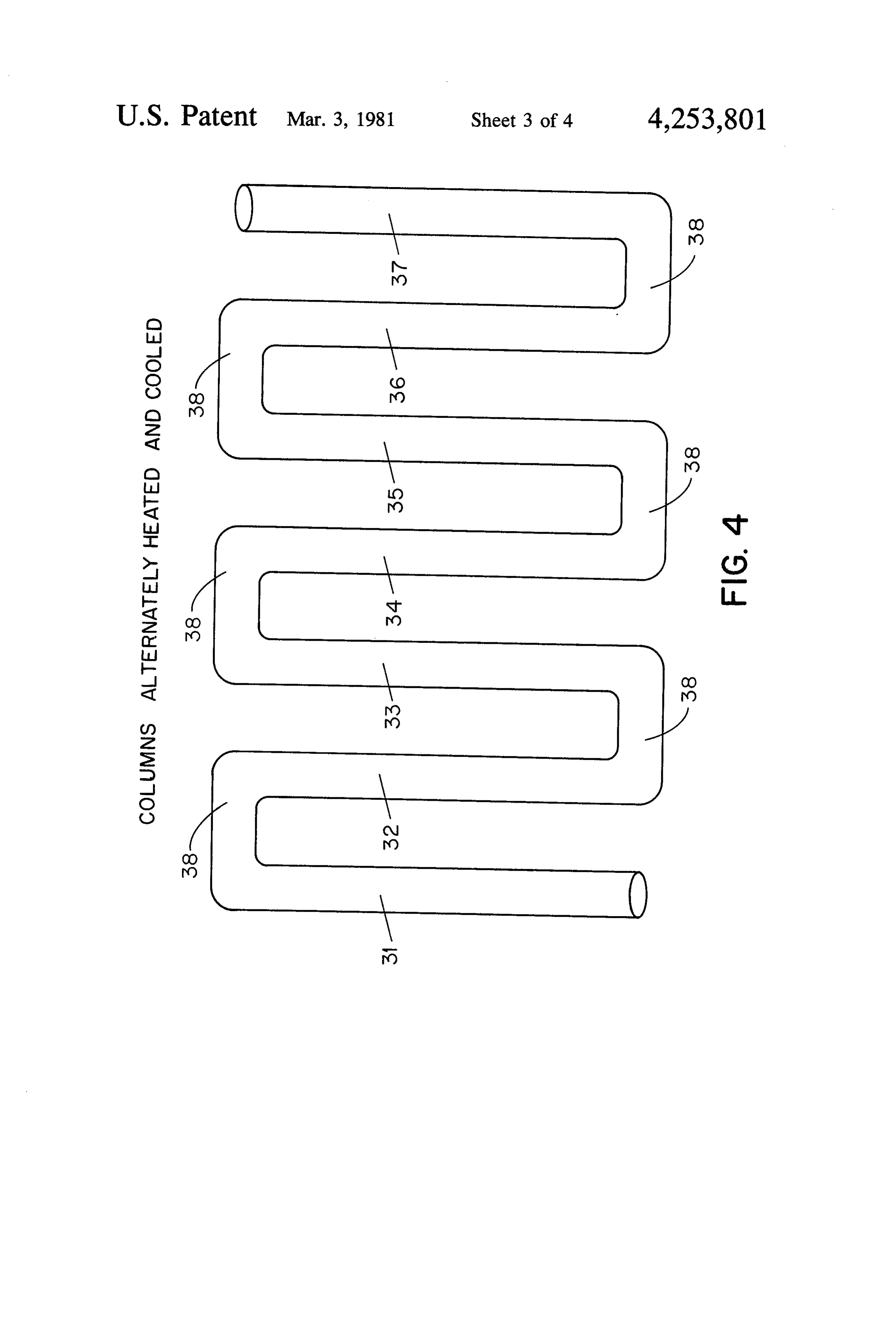
ployed to solar hydronic systems to provide a convect will flow between the two. Similarly if 22 is heated and ing liquid pump moving heat transferring liquids to 21 cooled there will be a heated flow. storage, to collectors and to living areas etc. Referring now to FIG. 4 when arms or tubes 31, 33, Clarification of mechanisms and embodiments is 35, and 37 are heated to continually heat the fluid within given in referring to the drawings. them a column of fluid will have a reduced density and FIG. 1 of the drawings depicts a single heated tower a convection pressure tending to cause the fluid to rise producing a convective flow to move air through a when 32, 34, and 36 are cooled relative to the tempera storage system and to heat a house. tures of the heated tubes then the relatively higher den FIG. 2 of the drawings shows a series convection of sity will cause the fluid to fall in these tubes or arms. heated convection columns which does not produce 10 The alternate upward and downward movements and much addition of the pressures of the columns. pressures are additive to produce a flow from 31 to 37. FIG. 3 shows an individual link form a series chain in The process and the flow is reversible by keeping 31, 33, which there is now pressure differential developed. 35 and 37 cool and heating 32, 34, and 36. Connecting FIG. 4 shows a true series additive hot-cold convec means 38 joins alternate hot and cold convection col
umns. Heating tubes 31, 33, 35, 37, as well as cooling
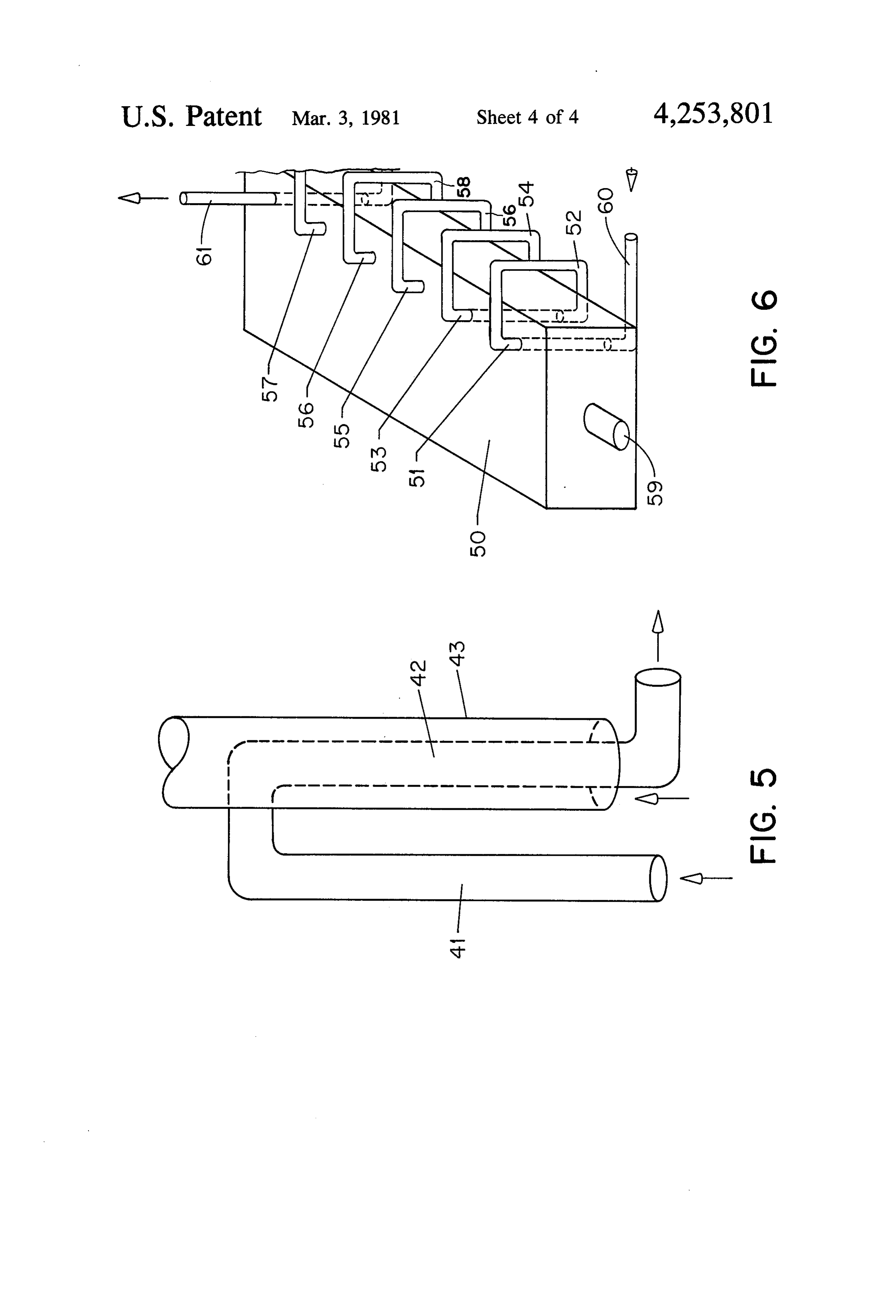
FIG. 5 shows one method of cooling a cooled column tubes 32, 34, and 36 may be any type of sealed cavity using a cooling convection sleeve around the cooled such as elongated rectangular boxes, cylinders, hollow columns.
FIG. 6 shows a series convection pump in which the columns, heating sealed sections of a plenum etc. In the case of tubes 31, 33, 35, 37 these need not be actually alternate heated arms are heated by a hot solar energy tubular in shape storage unit and the cooled arms are cooled by the sections of a solarbutcollector may be verticle or inclined sealed panel.
ambient surrounding air. In FIG. 5 of the drawings heating tube or arm 41 Referring then to FIG. 1 of the drawings, duct 1 causes fluid to flow to descending receives cooler air into solar collecting box 2 in which thereby heating 42 and heating fluid intube or arm 42 cavity between light energy entering through front surface glass plate, 25 tubes 42 and 43 causing the fluid in the cavity between not shown, strikes black absorber plate 3 on which 42 and 43 to rise thereby cooling tube 42 and its con radiant energy is absorbed and converted to heat thereby heating air admitted through 1 and causing tents and assisting downward convection within 42. In expanded air to rise through duct 4 into tall insulated other embodiments radiators and cooling fins are used column 5 thereby heating column 5 and providing a 30 to cool 42.
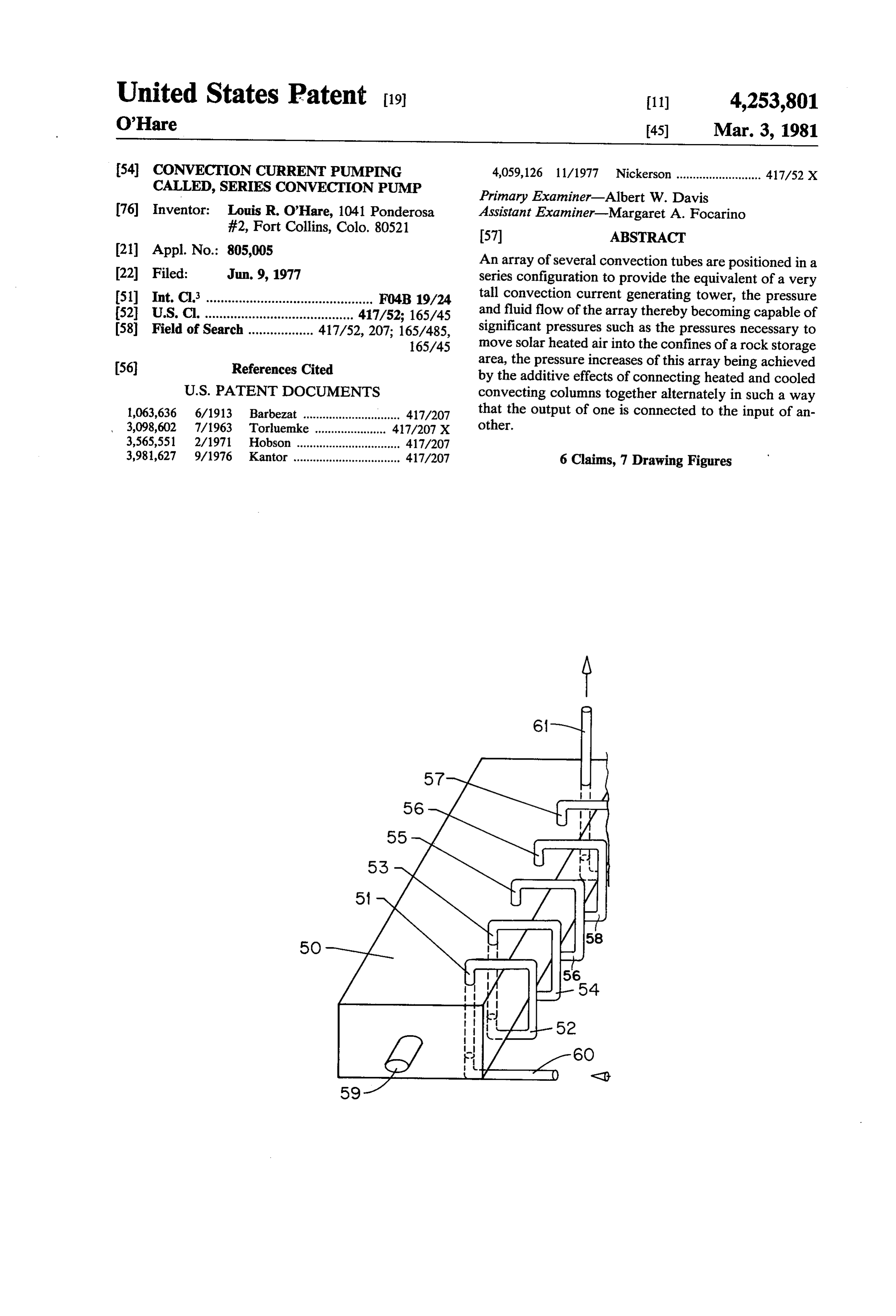
high heated column in which a large convection current In FIG. 6 a typical solar heat storage area 50 is used and pressure can develope to move heated column of air to heat the alternate heated arms or tubes 51, 53,55, 56, 57, 58 which alternate with cooled tubes 52, 54, 56, 58, to descending column 6 in which airstream is slightly and cooled. The convection pressure from column 5 is vari 60 and are connected to them as 31, 33, 35 and 37 able depending upon how high the temperature is over 35 are connected to 34,32, and 36 of FIG. 4. That is to say ambient and depending as well upon the height of the they are connected in a series configuration providing a column and the cooling produced in descending column single flow-through passage. Cooled elements in one 6. However, pressures here are adequate to move the embodiment each have a convecting, cooling shroud as heated air through storage area 7 and through living shroud 43 in FIG. 5 or they may have fins or other area 8. In turn air entering 1 may be received from radiators. Outlet duct 58, according to a principal em living area 8 or from cool side of storage area 7 or from bodiment, exits moving fluid under pressure to the inlet out door ambient by means of suitable valving and duct port of a solar collector (not shown) and heated fluid ing as is practiced in the present state of the art which from the collector is admitted to storage heating inlet valving and ducting is not shown here. port 59. The total effect of the action between inlet 60 Referring now to FIG. 2 of the drawings which is 45 and outlet 58 is simply to move fluid under pressure and used merely to illustrate an unsatisfactory juxtaposition it may be used in any situation where heating and/or of columns in which very little convection and pressure cooling are available as where geothermal heat is avail differential is produced. In arm 11 a column of fluid able adjacent to a cooling body of water or glacial ice. such as air is heated when the arm is heated. The col The principal embodiment, however, involves its use in umn of air, or for that matter any fluid, rises and de 50 moving heat transfer fluids in solar energy applications. scends in arm 12 descending rapidly at first as it cools In one embodiment therefore the alternating heated and gains weight then more slowly when 2 is heated and tubes are heated directly by the solar panels as the tubes no longer able to cool the fluid moving through it. are placed inside of the panels or physically connected Externally heated arm 13 similarly heats and reduces to them and the alternate cooling tubes are cooled be the density of the fluid within it but when the heated 55 hind or aside of the solar collecting panels. In still an fluid of 13 reaches 14 and heats it then the fluid in 14 is other embodiment the heating of the heating tubes is no longer much heavier than the fluid in 13 and the fluid done by both the solar collecting panals and by storage in both 13 and 14 both tend to rise nearly equally and area heat. The cooling for the alternate cooling tubes is fluid flow from 13 to 14 is effectively curtailed. In the accomplished adjacent to the separate heating areas as same way if 15 is heated externally fluid convecting 60 described above.
from it to 16 will eventually cease for the same reason. I claim:
Some fluid could rise from arm 17 if it were externally 1. A passive solar energy operated system compris heated, but FIG. 2 merely illustrates an ineffective at 1ng:
tempt to produce a series of convecting columns. a multiple convection current production means Referring to FIG. 3 of the drawings arms 21 and 22 65 comprising an array of several elongated cavities are used to emphasize that when the temperatures in forming convection columns said convecting col any two succeeding arms are the same, convection will umns being of a twofold variety the one type pro cease but if 20 is heated and 22 is externally cooled fluid ducing convection fluid movement by means of
Page 8
heating and the other producing convecting fluid 5. A pump as in claim 1 in which the cooling of the movement by means of cooling cool convection tubes is accomplished by a cooling and jacket wherein the convection in the jacket produces a an alternate tube connection means coupling the out circulation which cools the cool convection tube. put fluid of a heating covection tube to the input 6. A passive solar energy operated system compris duct of a cooling convection tube and connecting ing: a multiple convection current production means the output end of a cooling convection column to comprising an array of several elongated cavities form the input of yet another subsequent heating tube ing convection columns said convecting columns being and so on providing a series of connected alternate 10 of a twofold variety the one type producing convection heating and cooling convection tubes so intercon fluid movement by means of heating and the other pro nected that the convection action of each tube adds ducing convection fluid movement by means of cooling and to the convective flow produced by the others and, convection tube heating providing a temperature an alternate tube connection means coupling the out rise for the alternate tubes that produce convection 15 put fluid of a heating convection tube to the input current by heating duct of a cooling convection tube and connecting and, the output end of a cooling convection column to convection tube cooling means providing a tempera the input of yet another subsequent heating tube ture decline for those alternate tubes causing con and so on providing a series of connected alternate vection current by cooling wherein the convection 20 heating and cooling convection tubes so intercon nected that the convection action of each tube adds tube heating means is a solar collector. to the convective flow produced by the others and, 2. A pump as in claim 1 in which the heating means is convection tube heating means providing a temper a solar energy storage unit into which the heating con ature rise for the alternate tubes that produce con vection tubes have been placed. vection current by heating 3. A pump as in claim 1 in which the convection tubes 25 and, or cavities are cylinders placed into solar energy ab convection tube cooling means providing a tempera sorbtion collectors. ture decline for those alternate tubes causing con 4. An air or fluid pump as in claim 1 in which the vection current by cooling, wherein the convec heating convection cavities are sealed segments of a tion tube heatingk isxi.provided by geothermal heat. solar energy collector. 30 ck ck k
Provenance
- Collection
- Cited prior art
- Original PDF
- patentimages.storage.googleapis.com →
- Filed
- 1977-06-09
- Pages
- 8
- Method
- pdftotext (the PDF's own text layer) + pdftoppm 300dpi page scans
- Source
- Google Patents bibliographic record
- Granted
- 1981-03-03
- Inventors
- Louis R. O'Hare
- Transcribed from
- patentimages.storage.googleapis.com →