patent · US4488208
Low brightness lens for circular fluorescent lamps
11 December 1984
Page 1 — bibliographic record
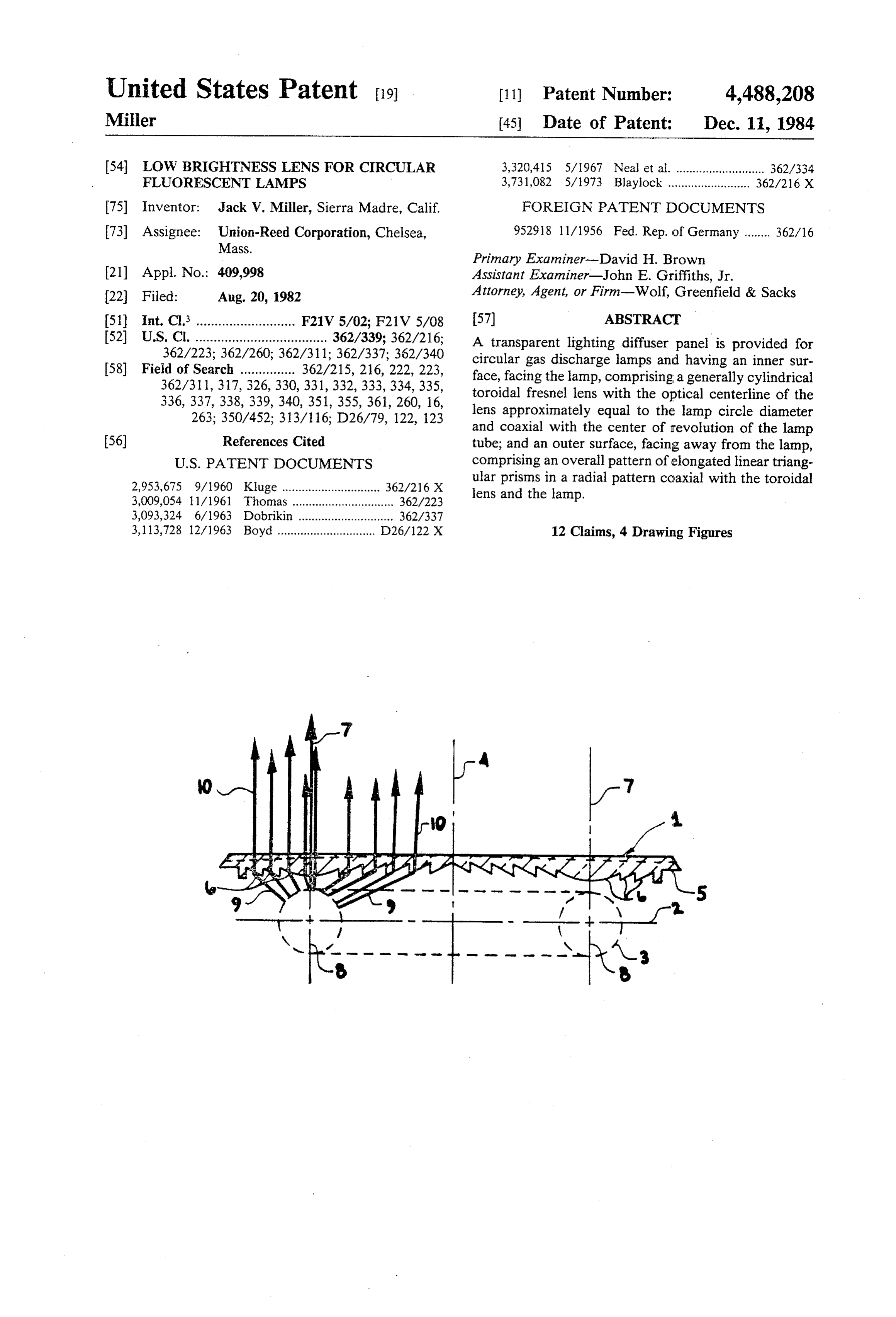
United States Patent 19 11 Patent Number: 4,488,208 Mier 45) Date of Patent: Dec. 11, 1984 54 LOW BRIGHTNESS LENS FOR CIRCULAR 3,320,415 5/1967 Neal et al. ........................... 362/334 FLUORESCENT LAMPS 3,731,082 5/1973 Blaylock ........................ 362/216 X 75 Inventor: Jack V. Miller, Sierra Madre, Calif. FOREIGN PATENT DOCUMENTS 73) Assignee: Union-Reed Corporation, Chelsea, 952918 11/1956 Fed. Rep. of Germany ....... 362/16 Mass.
Primary Examiner-David H. Brown 21) Appl. No.: 409,998 Assistant Examiner-John E. Griffiths, Jr. 22 Filed: Aug. 20, 1982 Attorney, Agent, or Firm-Wolf, Greenfield & Sacks (51) Int. Cl. ........................... F21V 5/02; F21V 5/08 57) ABSTRACT 52) U.S. Cl. .................................... 362/339; 362/216; A transparent lighting diffuser panel is provided for 362/223; 362/260; 362/311; 362/337; 362/340 circular gas discharge lamps and having an inner sur 58 Field of Search ............... 362/215, 216, 222, 223, face, facing the lamp, comprising a generally cylindrical 362/311, 317,326,330, 331, 332, 333,334, 335, toroidal fresnel lens with the optical centerline of the 336, 337, 338,339, 340, 351, 355, 361, 260, 16, lens approximately equal to the lamp circle diameter 263; 350/452; 313/116; D26/79, 122, 123 and coaxial with the center of revolution of the lamp 56) References Cited tube; and an outer surface, facing away from the lamp,
2,953,675 9/1960 Kluge .............................. 362/216 X ular prisms in a radial pattern coaxial with the toroidal 3,009,054 11/1961 Thomas............................... 362/223 lens and the lamp.
3,093,324 6/1963 Dobrikin ............................. 362/337 3,113,728 12/1963 Boyd .............................. D26/122 X 12 Claims, 4 Drawing Figures
Page 2
Drawing sheet — no readable text.
Page 3
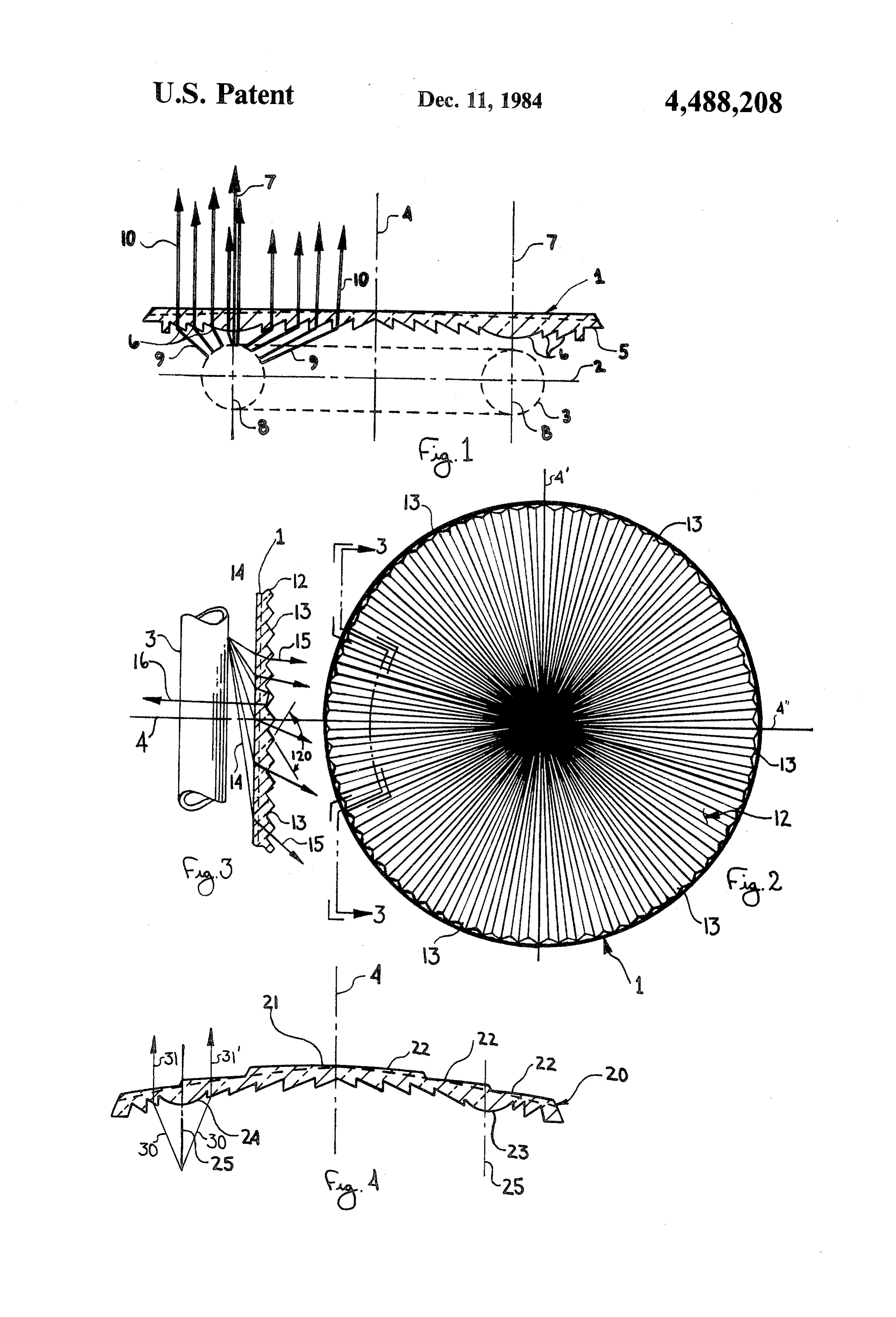
fresnel arrangement of a generally cylindrical toroidal
LOW BRIGHTNESS LENS FOR CRCULAR lens 6 with a circular optical centerline or an optical FLUORESCENT LAMPS center cylindrical ring 7 approximately the same diame BACKGROUND OF THE INVENTION ter as the lamp diameter 8. Divergent rays 9 from lamp 5 3 are substantially diected towards a more collimated
This invention relates to diffusing lens panels for pattern of rays 10.
controlling the light output from gas discharge lamps of In FIG. 2 a plan view of outer surface 12 of lens 1 is circular shape, such as the circline type fluorescent shown having an overall pattern of generally triangular lamps in general use, to direct the widely dispersed light male prisms 13 arranged in a radial pattern about the from the lamp into a directional beam of useful light, O central axis 4 of the lens and lamp. with reduced side glare and efficiency losses. In FIG. 3 prisms 13 on outer surface 12 of lens 1 are Circular fluorescent lamps have been widely used in shown having included angles of approximately 120 to lampholder fittings, such as those described in my in direct divergent rays 14 from lamp 3 into more colli ventions of U.S. Pat. Nos. 4,105,276 and 4,178,535, in mated rays 15, and to capture stray rays 16 which might which bare, exposed lamps are used as screw-in ceiling 5 emerge from the lens at excessively high angles with fixtures and as sources in portable lamps which use respect to the central axis 4 of the lens and lamp. shades to direct and control the light. In my co-pending In FIG. 4 an embodiment of the invention lens 20 is application entitled A CIRCULAR GAS DIS shown having a generally convex outer surface 21 com CHARGE REFLECTOR LAMP, Ser. No. 409,999, prising an overall pattern of tapered triangular prisms now U.S. Pat. No. 4,420,799, optical control of the lamp 20 22, arranged in concentric rows about the central axis 4 is shown by both reflective and refractive means, a of the lens. The inner surface 23 is generally concave refractive means shown therein being the male prism and is comprised of a fresnel arrangement of a generally pattern which faces away from the lamp.
The purpose of the present invention is to provide cylindrical toroidal lens 24 with a circular optical cen more precise and effective optical control than is possi 25 terline 25. Due to the cnvex configuration shown, the ble with the use of a single optical surface, to essentially lens area outside the circular optical centerline is closer to the plane of the lamp, and therefore must have a produce a spotlight or narrow beam floodlight from a shorter fluorescent source of circular shape, and also to pro lens areafocal length, ie: greater optical power, than the inside the circular optical centerline. This is duce a lens for the circular fluorescent source that is adapted for use in fixtures and lampholder fittings 30 evident in the greater angular change of incident rays 30 which also include light control by means of reflectors. to become collimated compared to that of incident rays
SUMMARY OF THE INVENTION In operation the fresnel toroidal lens generally colli A transparent lighting panel for circular fluorescent mates divergent rays from the lamp in radial planes lamps according to the present invention is provided 35 about the central axis of the lens and lamp, and the with an inner surface facing towards the lamp, and an triangular prisms generally collimate the divergent rays outer surface facing away from the lamp, with the panel from the lamp normal to the radial planes, whereby the oriented in a plane parallel to the plane of the circle of lens effectively directs widely divergent rays from the a lamp; the inner surface being provided with a fresnel lamp into more collimated rays parallel to the central arrangement of a cylindrical toroidal lens with the opti 40 axis of the lamp and lens.
cal centerline of the torus approximately the same diam I claim:
eter and coaxial with the circular lamp, and the outer 1. A lighting diffuser for a circular gas discharge surface being provided with an overall pattern of elon lamp comprising, gated linear and gnerally triangular prisms in a radial a light-transmitting panel, pattern coaxial with the toroidal lens of the inner sur 45 said panel having an overall pattern on one face face. A preferred embodiment provides a lens which is comprising a Fresnel lens arrangement having an generally convex on the outer surface, and is generally optical center cylindrical ring, said lens focus concave on the inner surface. sing light from said lamp into a plurality of paral BRIEF DESCRIPTION OF THE DRAWINGS 50 lel rays, which ring intersecting which lamp substantially along its entire length,
FIG. 1 is a cross-sectional view of the lens according said panel having a pattern on its other face com to the invention, taken along the central axis of the lens prising a radial pattern of elongated, substan and corcular fluorescent lamp, and showing the inner tially triangular prisms arranged about an axis lens surface structure; along the center of said ring. FIG. 2 is a plan view of the outer surface of a circular 55 2. A lighting diffuser for a circular gas discharge embodiment of the lens according to the invention; lamp according to claim 6 in which the Fresnel lens FIG. 3 is a cross-sectional view of a portion of the arrangement is asymmetrical in optical power, with a lens of FIG. 2, taken along line 3-3; and greater power outside the optical ring and a lesser FIG. 4 is a cross-sectional view of a preferred em power inside the optical ring of the lens arrangement. bodiment of the lens according to the invention, show 60 3. A lighting diffuser for a circular gas discharge ing a convex/concave configuration. lamp according to claim 1 in which the triangular DETAILED DESCRIPTION OF THE prisms in the radial pattern on the surface of the panel DRAWINGS are tapered to a point at the center of the radial pattern. 4. A lighting diffuser for a circular gas discharge
In FIG. 1 a lens 1 being a generally transparent panel 65 lamp according to claim 1 in which the panel is concave is shown oriented in a plane generally parallel to plane on the surface facing the lamp.
2 of a circular gas discharge lamp 3 having a central axis 5. A lighting diffuser for a circular gas discharge 4. Lens 1 has an inside surface 5 which comprises a lamp according to claim 1 wherein the pattern of prisms
Page 4
is symmetrical with respect to the centerline of the of prisms is bordered on its outer edge by a second panel. pattern of elongated triangular prisms arranged in a 6. A lighting diffuser for a circular gas discharge radial pattern.
lamp according to clain wherein each of the prisms in 10. A lighting diffuser for a circular gas discharge said radial pattern are elongated tetrahedrons: 5 lamp according to claim 9 wherein the prisms in the 7. A lighting diffuser for a circular gas discharge second pattern are tapered in a direction toward the lamp according to claim wherein the base of each center of said panel.
tetrahedral prism faces the lamp. 11. A lighting diffuser for a circular gas discharge 8. A lighting diffuser for a circular gas discharge lamp according to claim 9 wherein the prisms in the lamp according to claim 7 wherein the included angle O second pattern are truncated, elongated tetrahedrons. between two sides of the tetrahedron opposite the base 12. A lighting diffuser for a circular gas discharge is 120 degrees. lamp according to claim 9 wherein the prisms in the 9. A lighting diffuser for a circular gas discharge radial pattern and in the second radial pattern form lamp according to claim 1 wherein the pattern of prisms concentric rows.
does not extend to the edge of said panel and the pattern 15 ar s s
Page 5
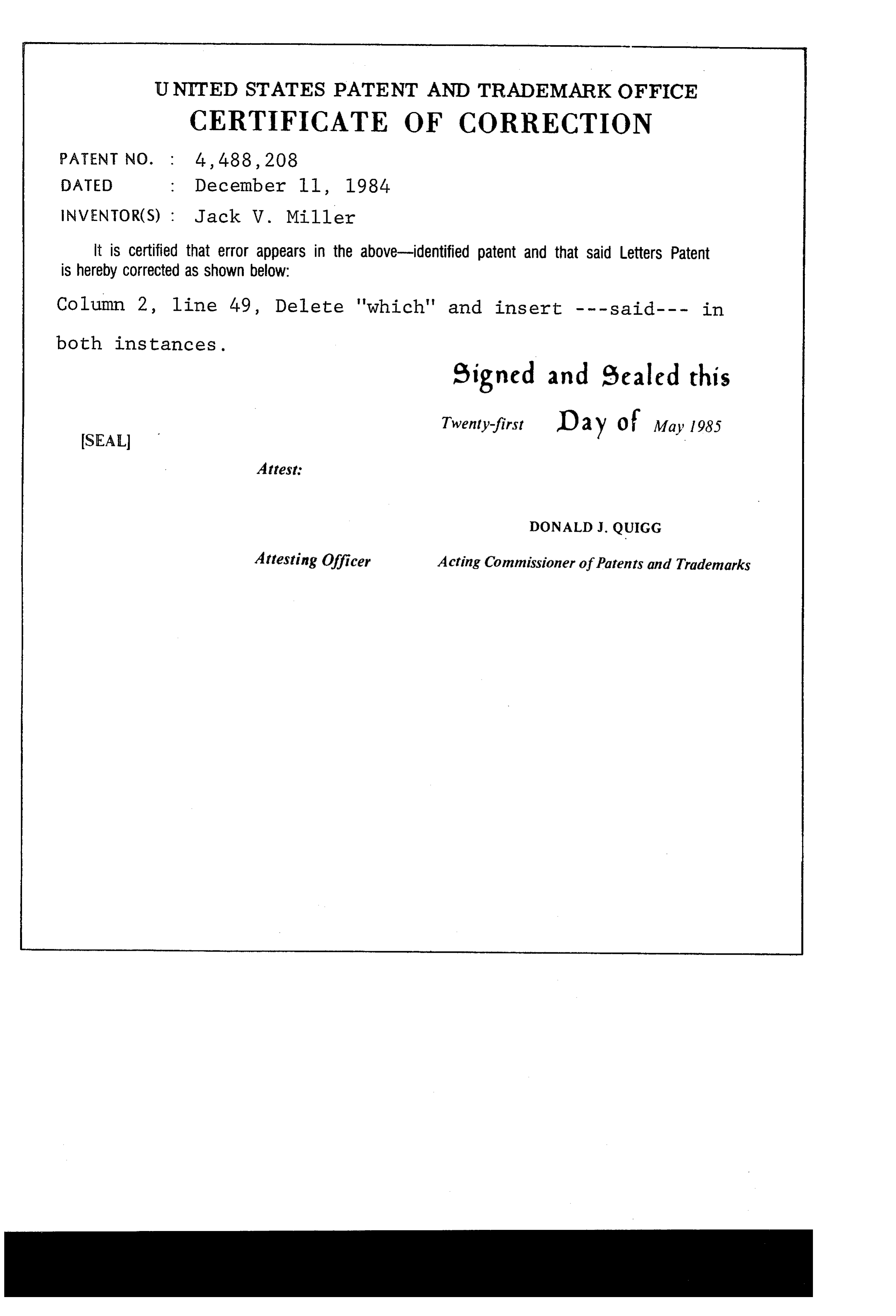
UNITED STATES PATENT AND TRADEMARK OFFICE
CERTIFICATE OF CORRECTION
INVENTOR(S) : Jack W. Miller it is certified that error appears in the above-identified patent and that said Letters Patent is hereby Corrected as shown below:
Column 2, line 49, Delete "which" and insert --- said.--- in both instances.
signed and escaled this
Twenty-first Day of May 1985
SEAL
Attest:
DONALD J. QUIGG
Attesting Officer Acting Commissioner of Patents and Trademarks
Provenance
- Collection
- Cited prior art
- Original PDF
- patentimages.storage.googleapis.com →
- Filed
- 1982-08-20
- Pages
- 5
- Method
- pdftotext (the PDF's own text layer) + pdftoppm 300dpi page scans
- Source
- Google Patents bibliographic record
- Granted
- 1984-12-11
- Inventors
- Jack V. Miller; UNION REED CORP
- Transcribed from
- patentimages.storage.googleapis.com →