patent · US4371029
Latent heat accumulator
1 February 1983
Page 1 — bibliographic record
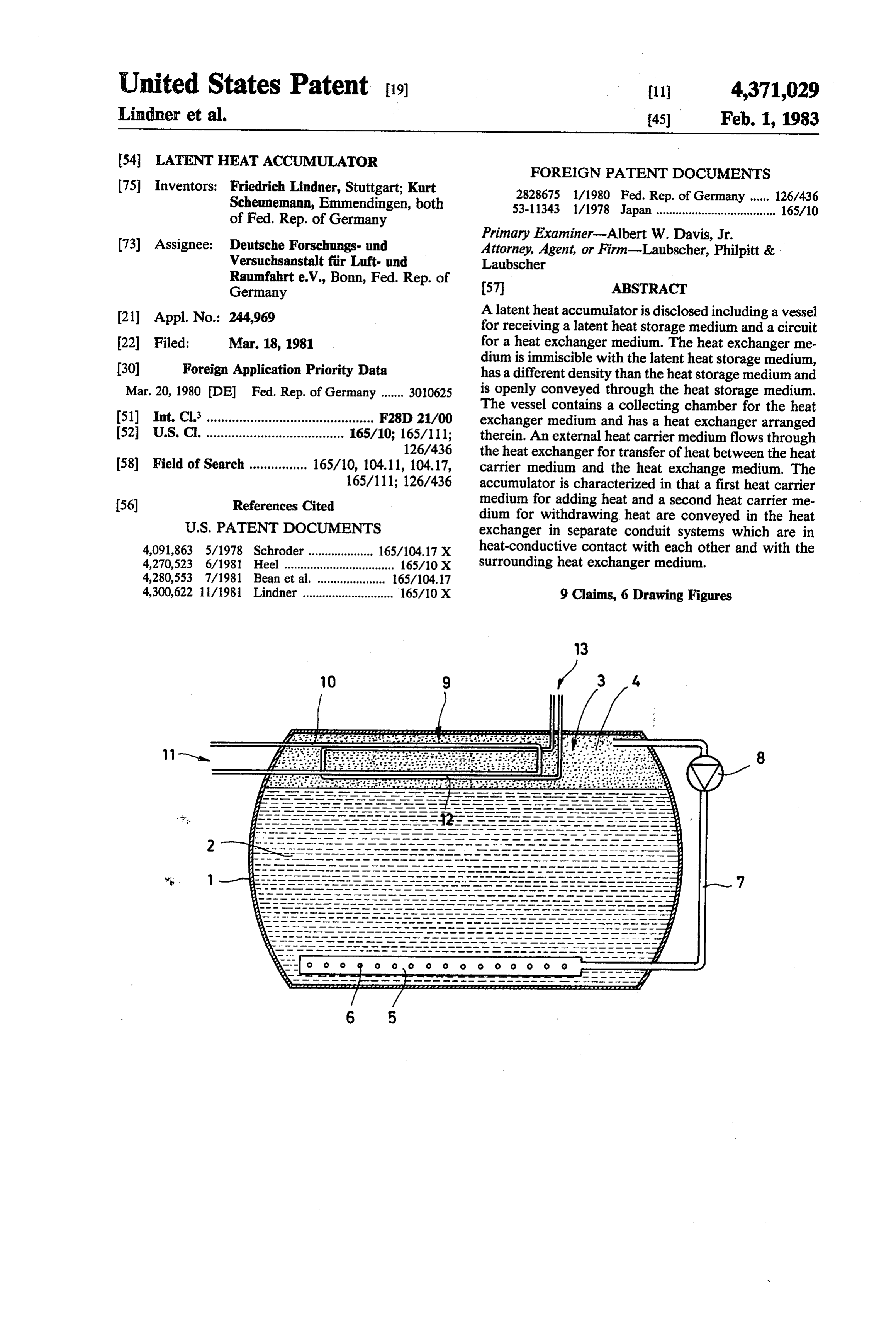
United States Patent (19) 11 4,371,029 Lindner et al. 45) Feb. 1, 1983 (54 LATENT HEAT ACCUMULATOR FOREIGN PATENT DOCUMENTS 75) Inventors: Friedrich Lindner, Stuttgart; Kurt 2828675 l/1980 Fed. Rep. of Germany ...... 126/436 Scheunemann, Emmendingen, both 53-11343 1/1978 Japan ..................................... 165/10 of Fed. Rep. of Germany 73) Assignee: Deutsche Forschungs- und Primary Examiner-Albert W. Davis, Jr. Versuchsanstalt fir Luft- und
Attorney, Agent, or Firm-Laubscher, Philpitt &
Laubscher
Raumfahrt e.V., Bonn, Fed. Rep. of 57 ABSTRACT
Germany (21) Appl. No.: 244,969 A latent heat accumulator is disclosed including a vessel for receiving a latent heat storage medium and a circuit 22 Filed: Mar. 18, 1981 for a heat exchanger medium. The heat exchanger me (30) Foreign Application Priority Data dium is immiscible with the latent heat storage medium, has a different density than the heat storage medium and
Mar. 20, 1980 DE Fed. Rep. of Germany ....... 301.0625 is openly conveyed through the heat storage medium. The vessel contains a collecting chamber for the heat 51) Int. C. .............................................. F28D 21/00 exchanger medium and has a heat exchanger arranged 52 U.S.C. ...................................... 165/10; 165/111; therein. An external heat carrier medium flows through 126/436 the heat exchanger for transfer of heat between the heat 58) Field of Search ................ 165/10, 104.11, 104.17, carrier medium and the heat exchange medium. The 165/111; 126/436 accumulator is characterized in that a first heat carrier (56) References Cited medium for adding heat and a second heat carrier me dium for withdrawing heat are conveyed in the heat
4,091,863 5/1978 Schroder .................... 165/104.17 X heat-conductive contact with each other and with the 4,270,523 6/1981 Heel .................................. 165/10 X surrounding heat exchanger medium. 4,280,553 7/1981 Bean et al. . . 165/104.17 4,300,622 li/1981 Lindner ............................ 165/10 X 9 Claims, 6 Drawing Figures
Page 2
Drawing sheet — no readable text.
Page 3
Drawing sheet — no readable text.
Page 4
Drawing sheet — no readable text.
Page 5
Drawing sheet — no readable text.
Page 6
Drawing sheet — no readable text.
Page 7
Drawing sheet — no readable text.
Page 8
at the same time. The latent heat accumulator then acts
LATENT HEAT ACCUMULATOR as a buffer, i.e. heat is stored when the addition of heat is greater than the withdrawal of heat whereas heat is
BACKGROUND OF THE INVENTION extracted when the withdrawal of heat is greater than The invention relates to a latent heat accumulator 5 the addition of heat. If heat is added and withdrawn at comprising a vessel for receiving a latent heat storage the same time the transfer of heat from the system add medium and a circuit for a heat exchanger medium, this ing heat to the system withdrawing heat can be direct, being immiscible with the latent heat storage medium, only the difference will be supplied or received by the having a different density to the heat storage medium 10 surrounding heat exchanger medium. and being openly conveyed through the storage me A preferred embodiment of the latent heat accumula dium, a collecting chamber being provided in the vessel tor is provided with exchanger surfaces in heat-conduc for the heat exchanger medium, a heat exchanger being tive contact with the heat exchanger medium, these disposed in this collecting chamber, an external heat being, in the main, vertical surfaces. This has the advan carrier medium flowing through this heat exchanger, 15 tage that particles of the displaced heat storage medium, which brings about a transfer of heat between heat which are to be formed in the heat exchanger medium carrier medium and heat exchanger medium. and are deposited on the heat exchanger surfaces, fall BRIEF DESCRIPTION OF THE PRIOR ART downwards under the influence of gravity and back into the heat storage substance again.
Such a device is described in U.S. Pat. No. 2,969,894. In the case of a latent heat accumulator comprising A latent heat"accumulator of this type enables a very 20 melting conduits in the storage vessel, which are in effective transfer of heat from the heat exchanger me heat-conductive contact with a conduit supplying the dium to the heat storage medium and vice versa since heat exchanger medium to the heat storage medium and the liquid exchanger medium is freely conveyed lead from this conduit into the collecting chamber, it through the heat storage medium and therefore comes 25 can be advantageously provided that the melting con in direct contact with it. Due to the difference in density duits have heat carrier medium flowing through them. the liquid heat exchanger medium, after it has passed For example, the melting conduits can have the first through the heat storage medium, is collected in a col heat lecting chamber, for example above the heat storage It is, carrier medium adding heat flowing through them. however, also possible to have a heat pump dis medium. However, it has become apparent that with posed this process the heat exchanger medium can carry along 30 and forinattheleast second conduit system withdrawing heat a portion of the heat carrier medium small quantities of the heat storage medium despite its heated by the heat lacking miscibility with this heat storage medium. melting conduits. pump to be conveyed through the When the heat exchanger medium is conveyed in an In this case the melting conduits may be connected external circuit, e.g. through a heat exchanger, there is optionally in parallel to the conduit systems directed a risk that the displaced substance may be deposited and 35 through the heat exchanger and optionally in series to accumulate at critical points, e.g. in such external heat these conduit systems.
exchangers or in an internal overflow as described, for example, in the U.S. Pat. No. 4,086,958. This accumula In the case of a further, preferred embodiment of a tion may proceed so far that the circuit of the heat latent heat accumulator comprising melting conduits in exchanger medium is blocked. the storage vessel, these being in heat-conductive contact with a conduit supplying the heat exchanger
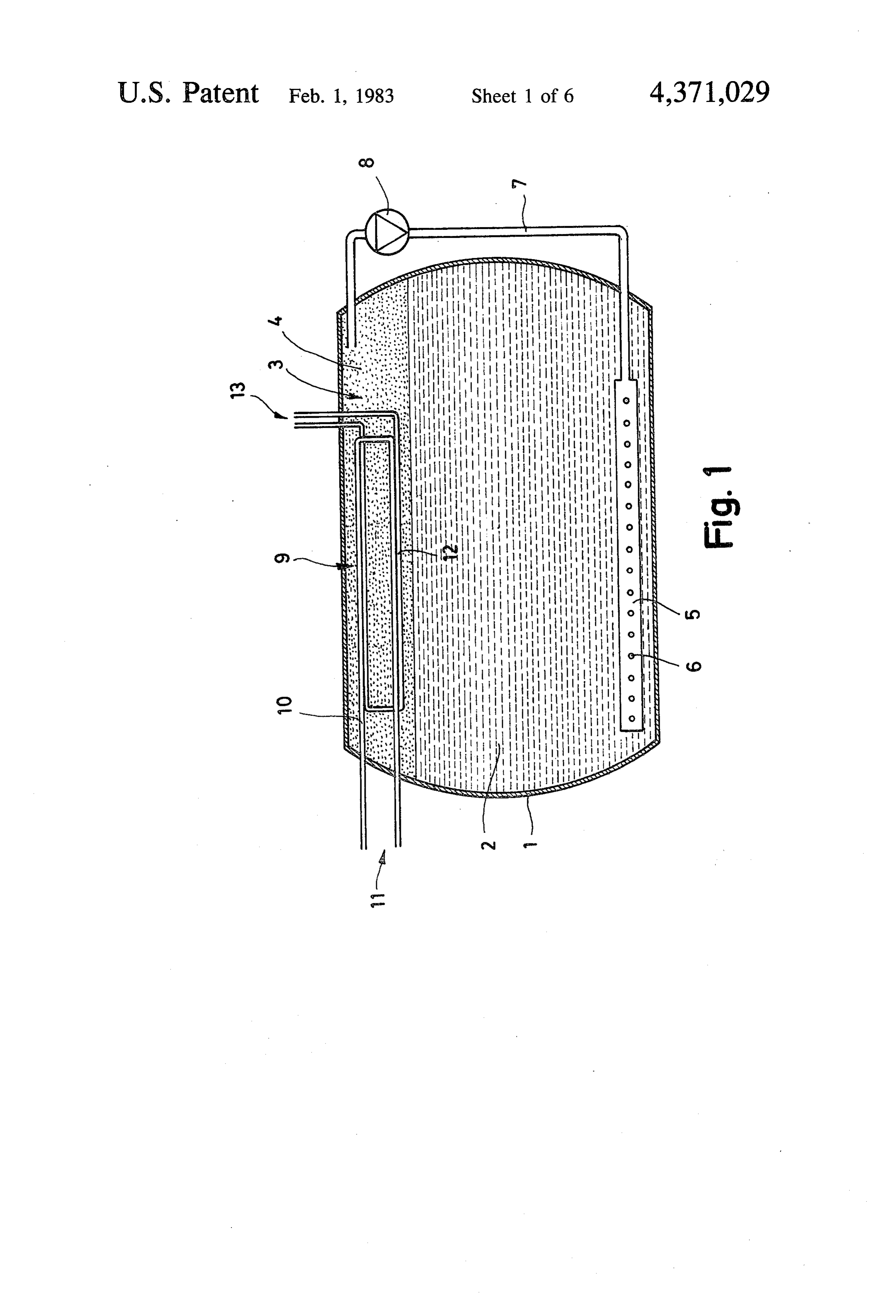
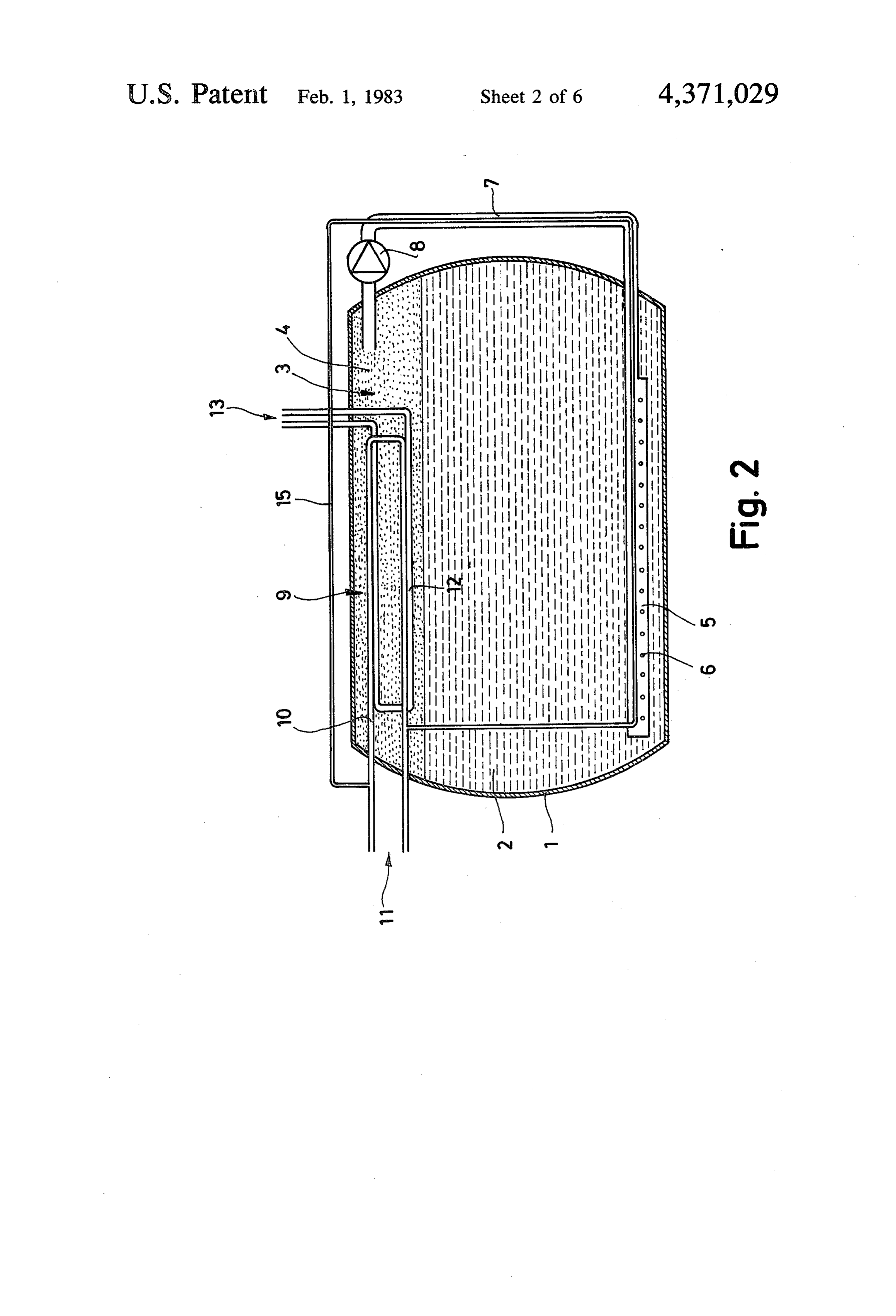
SUMMARY OF THE INVENTION medium to the heat storage medium and leading from The object of the invention is to improve a latent heat this conduit into the collecting chamber, a heat pump is accumulator of this type such that a displacement of provided in the second conduit system withdrawing heat storage substance by the heat exchanger medium 45 heat, a medium to be used being heatable via its conden does not impair the exchange of heat with the latent sor, and the melting conduits have at least a portion of heat accumulator even when operated for along period. the medium to be used flowing through them. This object is accomplished for a latent heat accumu Additional, advantageous developments of the inven lator of the type described at the beginning by convey tion are the subject matter of further subclaims. ing a first heat carrier medium adding heat and a second 50 BRIEF DESCRIPTION OF THE FIGURES heat carrier medium withdrawing heat in separate con duit systems, the two conduit systems being in heat-con The following specification of preferred embodi ductive contact with each other and with the surround ments of the invention serves to give more detailed ing heat exchanger medium. explanations in association with the drawings, in which A heat exchanger is therefore provided in the collect 55 FIG. 1 is a schematic sectional view of a latent heat ing chamber of the heat exchanger medium, in which accumulator comprising a heat exchanger in the heat the heat carrier medium adding heat, the heat carrier exchanger collecting chamber with two separate con medium withdrawing heat and the heat exchanger me duit systems;
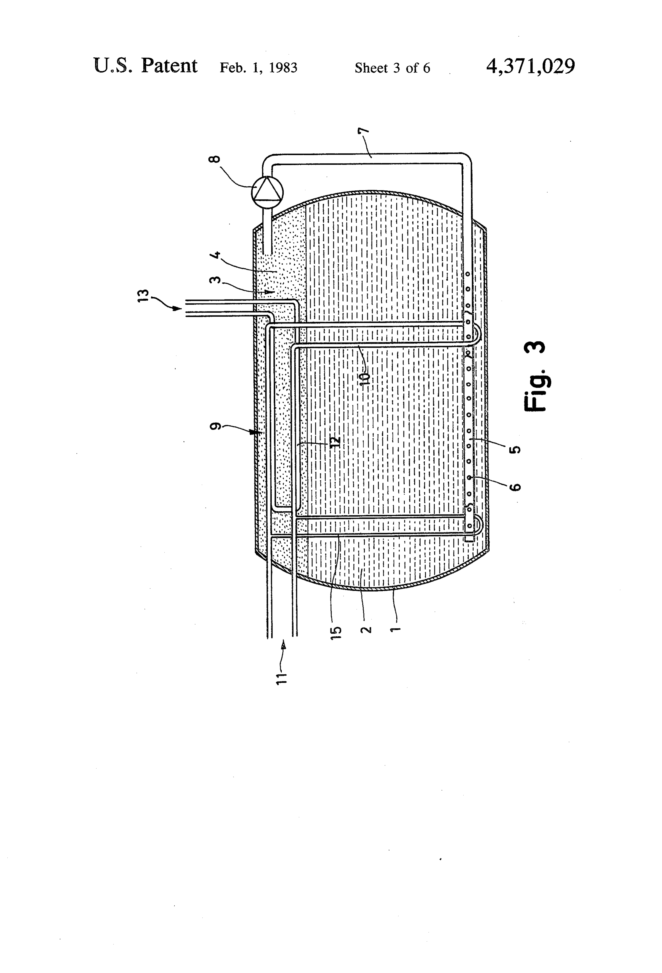
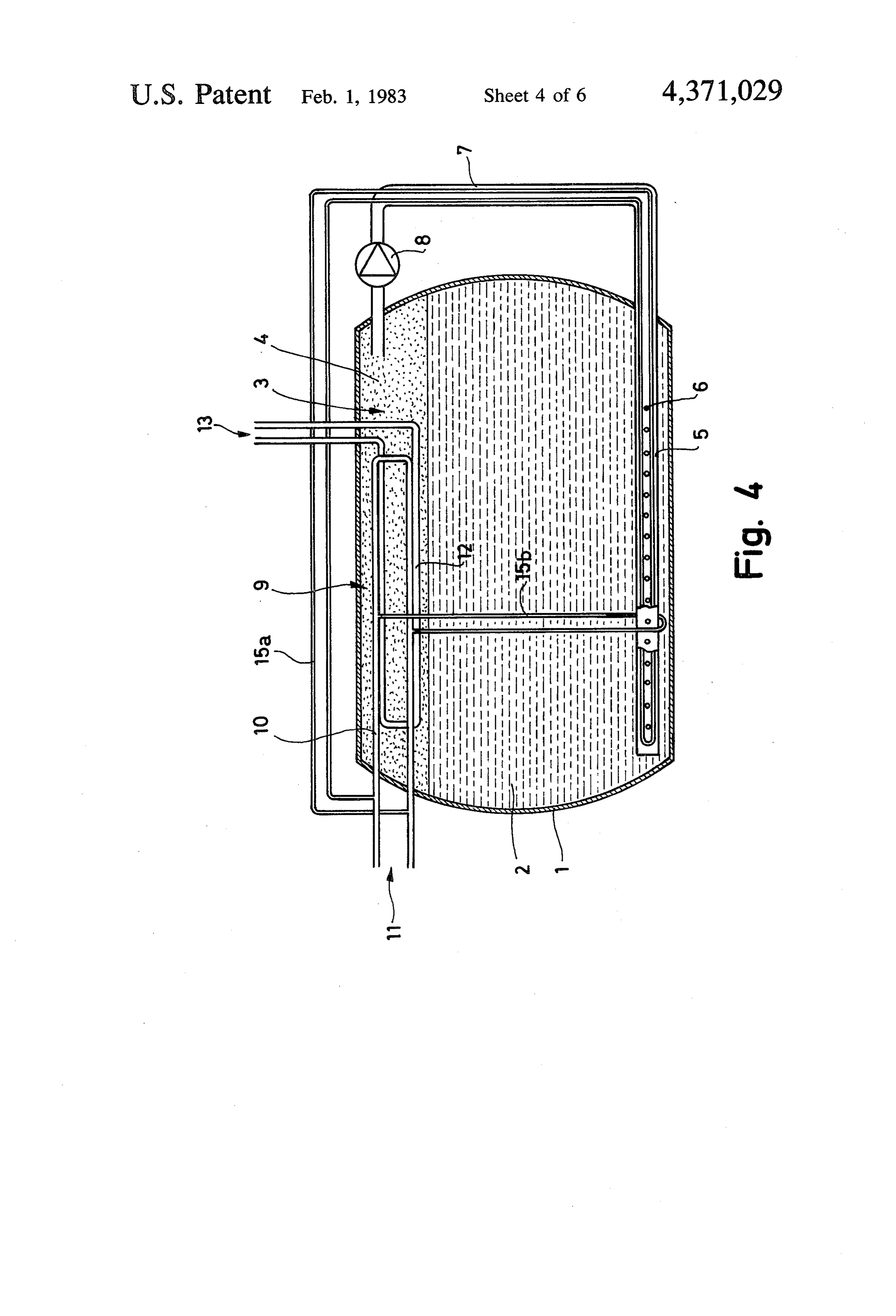
dium penetrating the heat storage substance are all in FIG. 2 is a view similar to FIG. 1 comprising a melt heat-conductive contact. The heat exchanger medium 60 ing conduit connected to the primary conduit; does not, therefore, have to be conducted through spe FIG. 3 is a view similar to FIG. 1 comprising a melt cial heat exchangers, in which the depositing of heat ing conduit connected in parallel to the primary circuit storage medium would be harmful. It is sufficient for and one connected in series into the primary circuit; the heat exchanger medium to be introduced into the FIG. 4 is a view similar to FIG. 1 comprising two heat storage medium again via a simple return conduit 65 melting conduits connected in parallel to the primary from the collecting chamber. circuit;
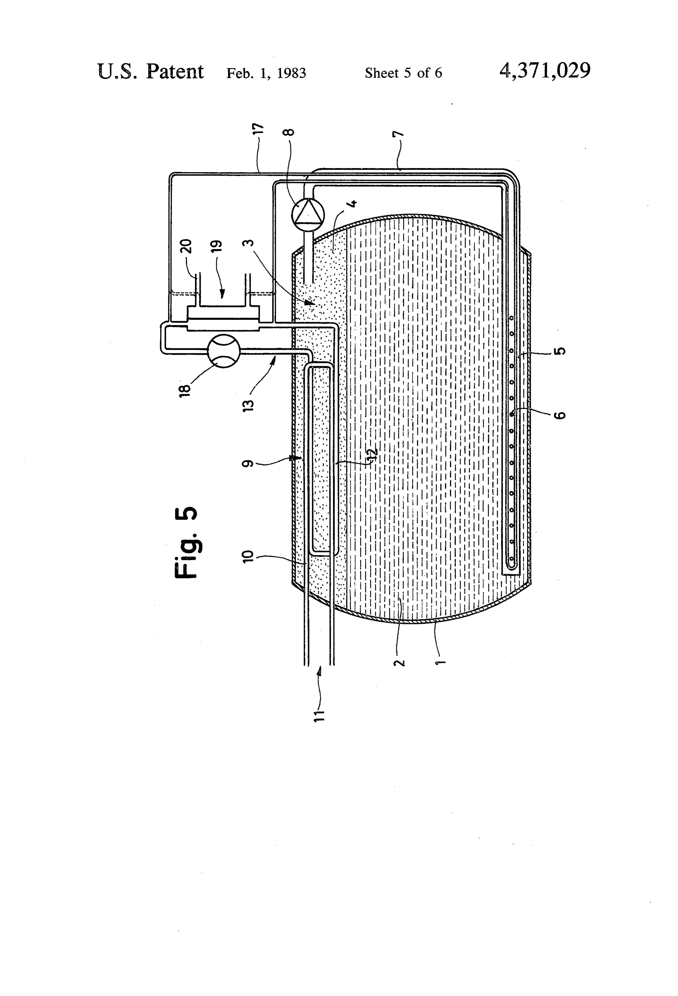
In addition, this arrangement has the great advantage FIG. 5 is a view similar to FIG. 1 comprising a heat that the addition and withdrawal of heat can take place pump and a heat exchanger in the secondary circuit and
Page 9
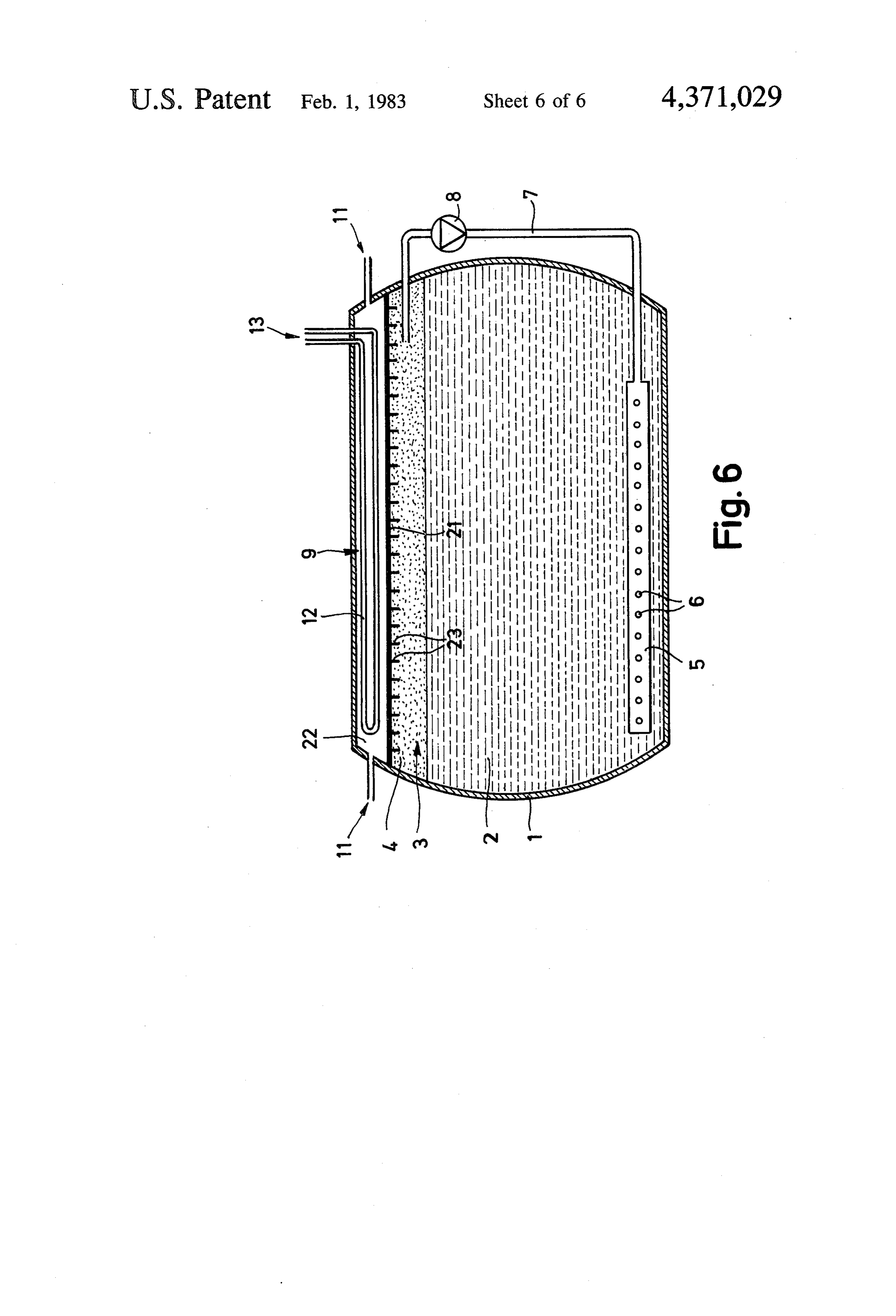
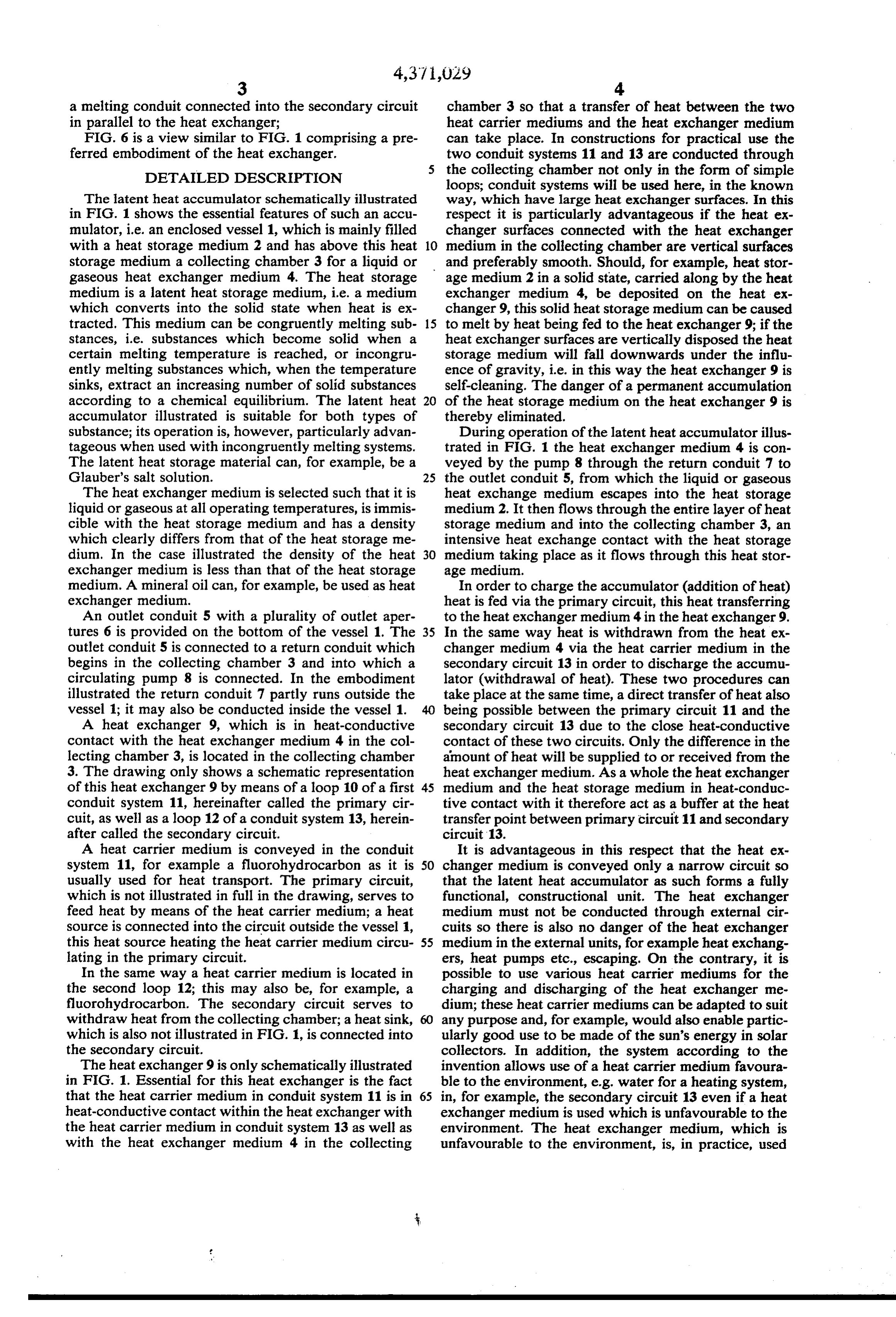
a melting conduit connected into the secondary circuit chamber 3 so that a transfer of heat between the two in parallel to the heat exchanger; heat carrier mediums and the heat exchanger medium FIG. 6 is a view similar to FIG. 1 comprising a pre can take place. In constructions for practical use the ferred embodiment of the heat exchanger. two conduit systems 11 and 13 are conducted through DETAILED DESCRIPTION the collecting chamber not only in the form of simple loops; conduit systems will be used here, in the known
The latent heat accumulator schematically illustrated way, which have large heat exchanger surfaces. In this in FIG. 1 shows the essential features of such an accu respect it is particularly advantageous if the heat ex mulator, i.e. an enclosed vessel 1, which is mainly filled changer surfaces connected with the heat exchanger with a heat storage medium 2 and has above this heat 10 medium in the collecting chamber are vertical surfaces storage medium a collecting chamber 3 for a liquid or and preferably smooth. Should, for example, heat stor gaseous heat exchanger medium 4. The heat storage age medium 2 in a solid state, carried along by the heat medium is a latent heat storage medium, i.e. a medium exchanger medium 4, be deposited on the heat ex which converts into the solid state when heat is ex changer 9, this solid heat storage medium can be caused tracted. This medium can be congruently melting sub- 15 to melt by heat being fed to the heat exchanger 9; if the stances, i.e. substances which become solid when a heat exchanger surfaces are vertically disposed the heat certain melting temperature is reached, or incongru storage medium will fall downwards under the influ ently melting substances which, when the temperature ence of gravity, i.e. in this way the heat exchanger 9 is sinks, extract an increasing number of solid substances self-cleaning. The danger of a permanent accumulation according to a chemical equilibrium. The latent heat 20 of the heat storage medium on the heat exchanger 9 is accumulator illustrated is suitable for both types of thereby eliminated.
substance; its operation is, however, particularly advan During operation of the latent heat accumulator illus tageous when used with incongruently melting systems. trated in FIG. 1 the heat exchanger medium 4 is con The latent heat storage material can, for example, be a veyed by the pump 8 through the return conduit 7 to Glauber's salt solution. 25 the outlet conduit 5, from which the liquid or gaseous The heat exchanger medium is selected such that it is heat exchange medium escapes into the heat storage liquid or gaseous at all operating temperatures, is immis medium 2. It then flows through the entire layer of heat cible with the heat storage medium and has a density storage medium and into the collecting chamber 3, an which clearly differs from that of the heat storage me intensive heat exchange contact with the heat storage dium. In the case illustrated the density of the heat 30 medium taking place as it flows through this heat stor exchanger medium is less than that of the heat storage age medium.
medium. A mineral oil can, for example, be used as heat In order to charge the accumulator (addition of heat) exchanger medium. heat is fed via the primary circuit, this heat transferring An outlet conduit 5 with a plurality of outlet aper to the heat exchanger medium 4 in the heat exchanger9. tures 6 is provided on the bottom of the vessel 1. The 35 In the same way heat is withdrawn from the heat ex outlet conduit 5 is connected to a return conduit which changer medium 4 via the heat carrier medium in the begins in the collecting chamber 3 and into which a secondary circuit 13 in order to discharge the accumu circulating pump 8 is connected. In the embodiment lator (withdrawal of heat). These two procedures can illustrated the return conduit 7 partly runs outside the take place at the same time, a direct transfer of heat also vessel 1; it may also be conducted inside the vessel 1. 40 being possible between the primary circuit 11 and the A heat exchanger 9, which is in heat-conductive secondary circuit 13 due to the close heat-conductive contact with the heat exchanger medium 4 in the col contact of these two circuits. Only the difference in the lecting chamber 3, is located in the collecting chamber amount of heat will be supplied to or received from the 3. The drawing only shows a schematic representation heat exchanger medium. As a whole the heat exchanger of this heat exchanger 9 by means of a loop 10 of a first 45 medium and the heat storage medium in heat-conduc conduit system 11, hereinafter called the primary cir tive contact with it therefore act as a buffer at the heat cuit, as well as a loop 12 of a conduit system 13, herein transfer point between primary circuit 11 and secondary after called the secondary circuit. circuit 13.
A heat carrier medium is conveyed in the conduit It is advantageous in this respect that the heat ex system 11, for example a fluorohydrocarbon as it is 50 changer medium is conveyed only a narrow circuit so usually used for heat transport. The primary circuit, that the latent heat accumulator as such forms a fully which is not illustrated in full in the drawing, serves to functional, constructional unit. The heat exchanger feed heat by means of the heat carrier medium; a heat medium must not be conducted through external cir source is connected into the circuit outside the vessel 1, cuits so there is also no danger of the heat exchanger this heat source heating the heat carrier medium circu- 55 medium in the external units, for example heat exchang lating in the primary circuit. ers, heat pumps etc., escaping. On the contrary, it is In the same way a heat carrier medium is located in possible to use various heat carrier mediums for the the second loop 12; this may also be, for example, a charging and discharging of the heat exchanger me fluorohydrocarbon. The secondary circuit serves to dium; these heat carrier mediums can be adapted to suit withdraw heat from the collecting chamber; a heat sink, 60 any purpose and, for example, would also enable partic which is also not illustrated in FIG. 1, is connected into ularly good use to be made of the sun's energy in solar the secondary circuit. collectors. In addition, the system according to the The heat exchanger 9 is only schematically illustrated invention allows use of a heat carrier medium favoura in FIG. 1. Essential for this heat exchanger is the fact ble to the environment, e.g. water for a heating system, that the heat carrier medium in conduit system 11 is in 65 in, for example, the secondary circuit 13 even if a heat heat-conductive contact within the heat exchanger with exchanger medium is used which is unfavourable to the the heat carrier medium in conduit system 13 as well as environment. The heat exchanger medium, which is with the heat exchanger medium 4 in the collecting unfavourable to the environment, is, in practice, used
Page 10
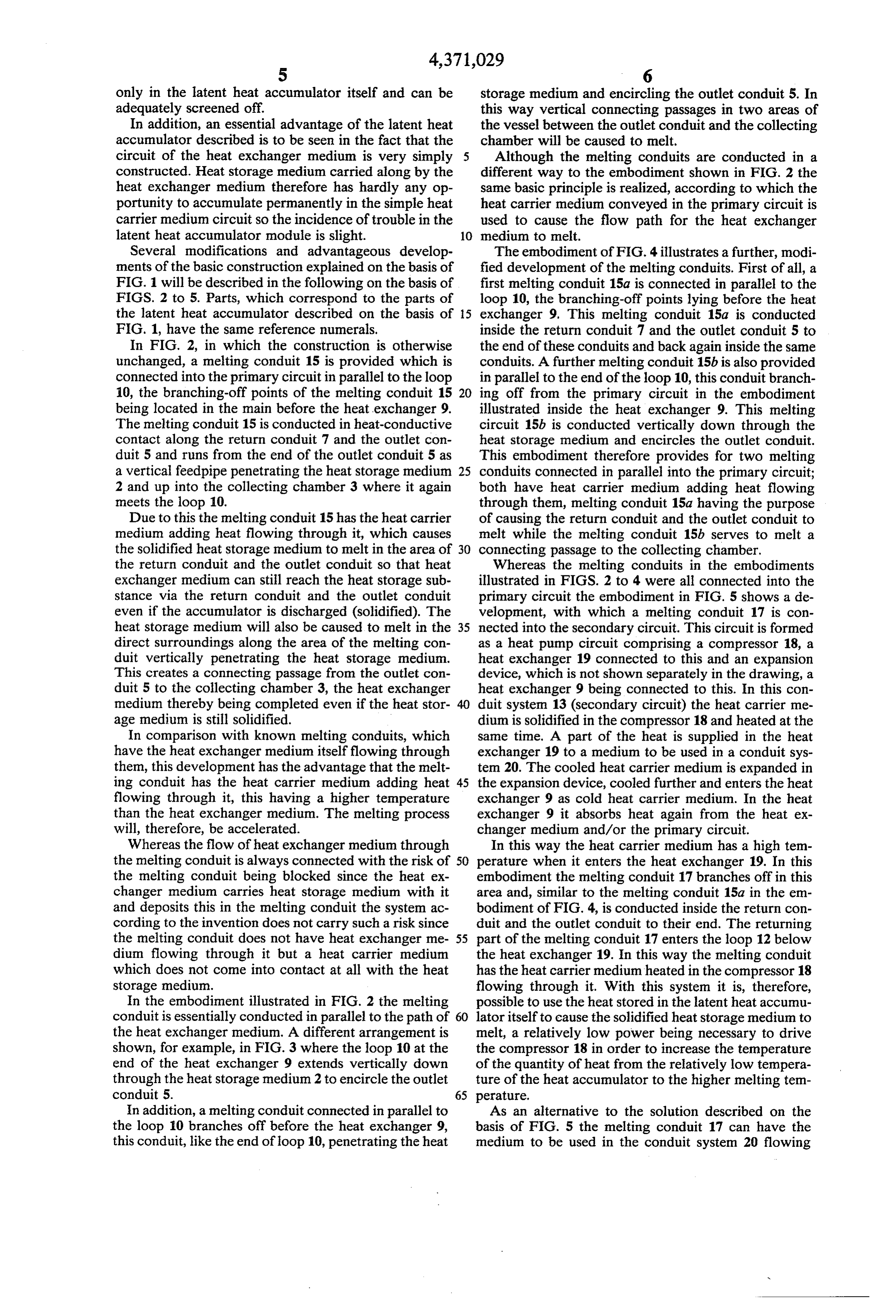
only in the latent heat accumulator itself and can be storage medium and encircling the outlet conduit 5. In adequately screened off. this way vertical connecting passages in two areas of In addition, an essential advantage of the latent heat the vessel between the outlet conduit and the collecting accumulator described is to be seen in the fact that the chamber will be caused to melt. circuit of the heat exchanger medium is very simply 5 Although the melting conduits are conducted in a constructed. Heat storage medium carried along by the different way to the embodiment shown in FIG. 2 the heat exchanger medium therefore has hardly any op same basic principle is realized, according to which the portunity to accumulate permanently in the simple heat heat carrier medium conveyed in the primary circuit is carrier medium circuit so the incidence of trouble in the used to cause the flow path for the heat exchanger latent heat accumulator module is slight. 10 medium to melt.
Several modifications and advantageous develop The embodiment of FIG. 4 illustrates a further, modi ments of the basic construction explained on the basis of fied development of the melting conduits. First of all, a FIG. 1 will be described in the following on the basis of first melting conduit 15a is connected in parallel to the FIGS. 2 to 5. Parts, which correspond to the parts of loop 10, the branching-off points lying before the heat the latent heat accumulator described on the basis of 15 exchanger 9. This melting conduit 15a is conducted FIG. 1, have the same reference numerals. inside the return conduit 7 and the outlet conduit 5 to In FIG. 2, in which the construction is otherwise the end of these conduits and back again inside the same unchanged, a melting conduit 15 is provided which is conduits. A further melting conduit 15b is also provided connected into the primary circuit in parallel to the loop in parallel to the end of the loop 10, this conduit branch 10, the branching-off points of the melting conduit 15 20 ing off from the primary circuit in the embodiment being located in the main before the heat exchanger 9. illustrated inside the heat exchanger 9. This melting The melting conduit 15 is conducted in heat-conductive circuit 15b is conducted vertically down through the contact along the return conduit 7 and the outlet con heat storage medium and encircles the outlet conduit. duit 5 and runs from the end of the outlet conduit 5 as This embodiment therefore provides for two melting a vertical feedpipe penetrating the heat storage medium 25 conduits connected in parallel into the primary circuit; 2 and up into the collecting chamber 3 where it again both have heat carrier medium adding heat flowing meets the loop 10. through them, melting conduit 15a having the purpose Due to this the melting conduit 15 has the heat carrier of causing the return conduit and the outlet conduit to medium adding heat flowing through it, which causes melt while the melting conduit 15b serves to melt a the solidified heat storage medium to melt in the area of 30 connecting passage to the collecting chamber. the return conduit and the outlet conduit so that heat Whereas the melting conduits in the embodiments exchanger medium can still reach the heat storage sub illustrated in FIGS. 2 to 4 were all connected into the stance via the return conduit and the outlet conduit primary circuit the embodiment in FIG. 5 shows a de even if the accumulator is discharged (solidified). The velopment, with which a melting conduit 17 is con heat storage medium will also be caused to melt in the 35 nected into the secondary circuit. This circuit is formed direct surroundings along the area of the melting con as a heat pump circuit comprising a compressor 18, a duit vertically penetrating the heat storage medium. heat exchanger 19 connected to this and an expansion This creates a connecting passage from the outlet con device, which is not shown separately in the drawing, a duit 5 to the collecting chamber 3, the heat exchanger heat exchanger 9 being connected to this. In this con medium thereby being completed even if the heat stor 40 duit system 13 (secondary circuit) the heat carrier me age medium is still solidified. dium is solidified in the compressor 18 and heated at the In comparison with known melting conduits, which same time. A part of the heat is supplied in the heat have the heat exchanger medium itself flowing through exchanger 19 to a medium to be used in a conduit sys them, this development has the advantage that the melt tem. 20. The cooled heat carrier medium is expanded in ing conduit has the heat carrier medium adding heat 45 the expansion device, cooled further and enters the heat flowing through it, this having a higher temperature exchanger 9 as cold heat carrier medium. In the heat than the heat exchanger medium. The melting process exchanger 9 it absorbs heat again from the heat ex will, therefore, be accelerated. changer medium and/or the primary circuit. Whereas the flow of heat exchanger medium through In this way the heat carrier medium has a high tem the melting conduit is always connected with the risk of 50 perature when it enters the heat exchanger 19. In this the melting conduit being blocked since the heat ex embodiment the melting conduit 17 branches off in this changer medium carries heat storage medium with it area and, similar to the melting conduit 15a in the em and deposits this in the melting conduit the system ac bodiment of FIG. 4, is conducted inside the return con cording to the invention does not carry such a risk since duit and the outlet conduit to their end. The returning the melting conduit does not have heat exchanger me 55 part of the melting conduit 17 enters the loop 12 below dium flowing through it but a heat carrier medium the heat exchanger 19. In this way the melting conduit which does not come into contact at all with the heat has the heat carrier medium heated in the compressor 18 storage medium. flowing through it. With this system it is, therefore, In the embodiment illustrated in FIG. 2 the melting possible to use the heat stored in the latent heat accumu conduit is essentially conducted in parallel to the path of 60 lator itself to cause the solidified heat storage medium to the heat exchanger medium. A different arrangement is melt, a relatively low power being necessary to drive shown, for example, in FIG. 3 where the loop 10 at the the compressor 18 in order to increase the temperature end of the heat exchanger 9 extends vertically down of the quantity of heat from the relatively low tempera through the heat storage medium 2 to encircle the outlet ture of the heat accumulator to the higher melting tem conduit 5. 65 perature.
In addition, a melting conduit connected in parallel to As an alternative to the solution described on the the loop 10 branches off before the heat exchanger 9, basis of FIG. 5 the melting conduit 17 can have the this conduit, like the end of loop 10, penetrating the heat medium to be used in the conduit system 20 flowing
Page 11
through it instead of the heat carrier medium of conduit cooling fluid such as freon would be conveyed in the system 14. Such an alternative development is indicated circuit.
in FIG. 5 by a dotted-line connection between the melt This embodiment could also, of course, have melting ing conduit 17 and the conduit system 20, the points of conduit branching off as described above. connection with the conduit system 20 being disposed at 5 We claim:
the inlet and outlet of the heat exchanger 19 respec 1. Latent heat accumulator comprising a vessel for tively. The melting conduit 17 is therefore connected in receiving a latent heat storage medium and a circuit for parallel to the actual circuit with the medium to be used, a heat exchanger medium, said heat exchanger medium which is not expressly illustrated in FIG. 5. being immiscible with the latent heat storage medium, This arrangement has the advantage that the melting O having a different density to the heat storage medium conduit 17 can also have the non-aggressive, environ and being openly conveyed through the storage me mentally favourable medium to be used flowing dium, a collecting chamber being provided in the vessel through it, in a heating system, for example, water. The for the heat exchanger medium, a heat exchanger being danger of chemically aggressive and dangerous heat 15 disposed in said collecting chamber, an external heat carrier mediums being given off inside the latent heat carrier medium flowing through said heat exchanger, accumulator will be further reduced. this heat exchanger bringing about a transfer of heat The geometrical arrangement of the melting conduits between heat carrier medium and heat exchange me may be selected in various ways; the essential factor is dium, characterized in that a first heat carrier medium merely that the melting conduits keep a circuit free for adding heat and a second heat carrier medium with drawing heat are conveyed in the heat exchanger (9) in the heat exchanger medium even if the heat storage 20 separate conduit systems (11, 13), the two conduit sys medium is solidified.
tems (11, 13) being in heat-conductive contact with
It is also possible to connect the melting conduits into each the circuit for the heat carrier medium in different ways other and with the surrounding heat exchanger according to the operating condition. For example, a 25 medium (4).
2. Latent heat accumulator as in claim 1, character melting conduit can be connected in series into the ized in that the exchanger surfaces of the heat ex conduit system 11 of the heat carrier medium adding changer (9), these surfaces being in heat-conductive heat at the commencement of operations while a contact with the heat exchanger medium (4), are in the change-over can take place after the first melting of the main vertical surfaces.
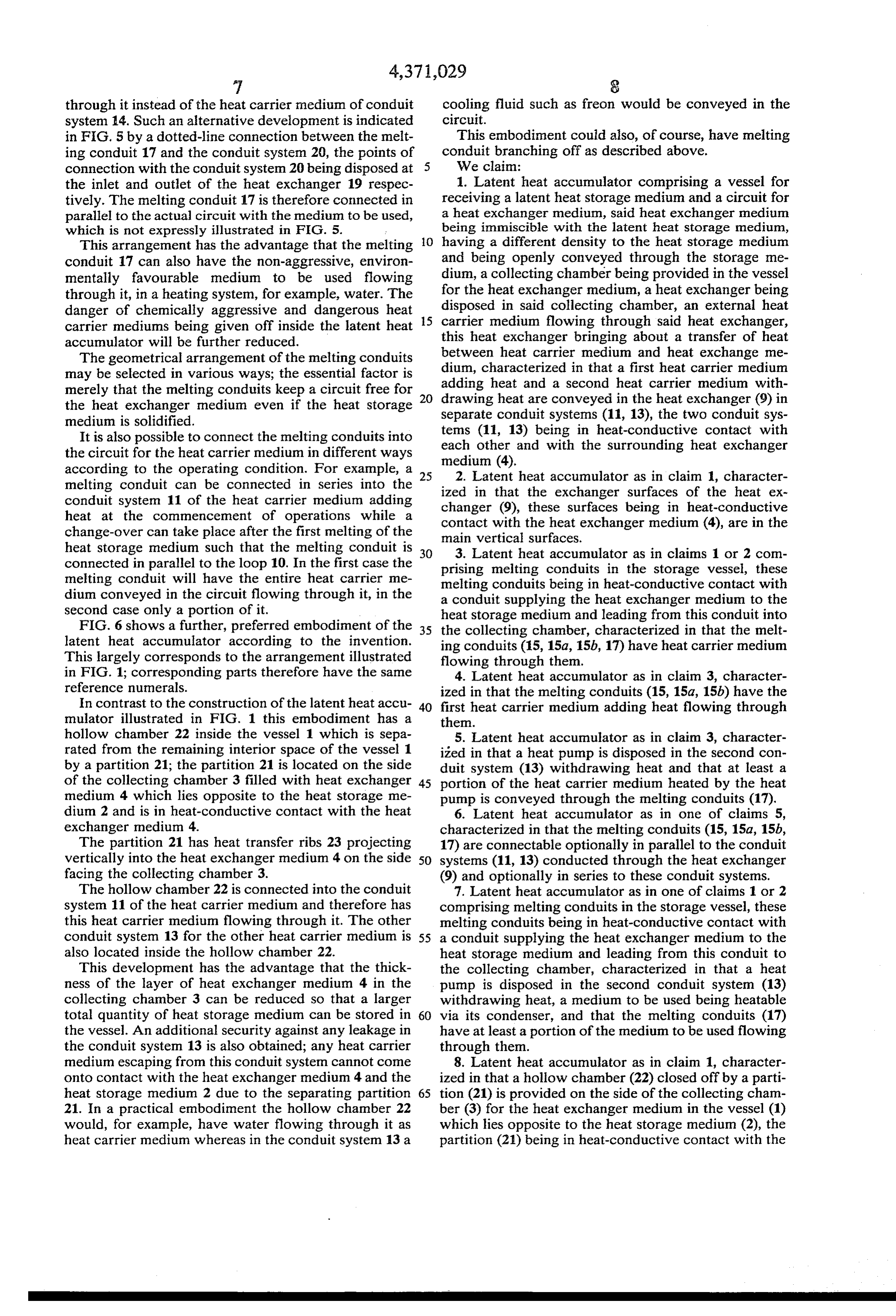
heat storage medium such that the melting conduit is 3. Latent heat accumulator as in claims 1 or 2 com connected in parallel to the loop 10. In the first case the prising melting conduits in the storage vessel, these melting conduit will have the entire heat carrier me melting conduits being in heat-conductive contact with dium conveyed in the circuit flowing through it, in the a conduit supplying the heat exchanger medium to the second case only a portion of it. heat storage medium and leading from this conduit into FIG. 6 shows a further, preferred embodiment of the 35 the collecting chamber, characterized in that the melt latent heat accumulator according to the invention.
This largely corresponds to the arrangement illustrated ing conduits (15, 15a, 15b, 17) have heat carrier medium flowing through them.
in FIG. 1; corresponding parts therefore have the same 4. Latent heat accumulator as in claim 3, character reference numerals. ized in that the melting conduits (15, 15a, 15b) have the In contrast to the construction of the latent heat accu 40 first heat carrier medium adding heat flowing through mulator illustrated in FIG. 1 this embodiment has a them.
hollow chamber 22 inside the vessel 1 which is sepa 5. Latent heat accumulator as in claim 3, character rated from the remaining interior space of the vessel 1 ized in that a heat pump is disposed in the second con by a partition 21; the partition 21 is located on the side duit system (13) withdrawing heat and that at least a of the collecting chamber 3 filled with heat exchanger 45 portion of the heat carrier medium heated by the heat medium 4 which lies opposite to the heat storage me pump is conveyed through the melting conduits (17). dium 2 and is in heat-conductive contact with the heat 6. Latent heat accumulator as in one of claims 5, exchanger medium 4. characterized in that the melting conduits (15, 15a, 15b, The partition 21 has heat transfer ribs 23 projecting 17) are connectable optionally in parallel to the conduit vertically into the heat exchanger medium 4 on the side 50 systems (11, 13) conducted through the heat exchanger facing the collecting chamber 3. (9) and optionally in series to these conduit systems. The hollow chamber 22 is connected into the conduit 7. Latent heat accumulator as in one of claims 1 or 2 system 11 of the heat carrier medium and therefore has comprising melting conduits in the storage vessel, these this heat carrier medium flowing through it. The other melting conduits being in heat-conductive contact with conduit system 13 for the other heat carrier medium is 55 a conduit supplying the heat exchanger medium to the also located inside the hollow chamber 22. heat storage medium and leading from this conduit to This development has the advantage that the thick the collecting chamber, characterized in that a heat ness of the layer of heat exchanger medium 4 in the pump is disposed in the second conduit system (13) collecting chamber 3 can be reduced so that a larger withdrawing heat, a medium to be used being heatable total quantity of heat storage medium can be stored in 60 via its condenser, and that the melting conduits (17) the vessel. An additional security against any leakage in have at least a portion of the medium to be used flowing the conduit system 13 is also obtained; any heat carrier through them.
medium escaping from this conduit system cannot come 8. Latent heat accumulator as in claim 1, character onto contact with the heat exchanger medium 4 and the ized in that a hollow chamber (22) closed off by a parti heat storage medium 2 due to the separating partition 65 tion (21) is provided on the side of the collecting cham 21. In a practical embodiment the hollow chamber 22 ber (3) for the heat exchanger medium in the vessel (1) would, for example, have water flowing through it as which lies opposite to the heat storage medium (2), the heat carrier medium whereas in the conduit system 13 a partition (21) being in heat-conductive contact with the
Page 12
heat exchanger medium (4) in the collecting chamber ized in that heat transfer ribs (23) projecting vertically (3), that one of the two heat carrier mediums is passed through the hollow chamber (22) and that the conduit into the heat exchanger medium (4) are disposed on the EE ESA, E. "" partition (21) closing offk theis hollow 9. Latent heat accumulator as in claim 8, character- k is chamber (22).
Provenance
- Collection
- Cited prior art
- Original PDF
- patentimages.storage.googleapis.com →
- Filed
- 1981-03-18
- Pages
- 12
- Method
- pdftotext (the PDF's own text layer) + pdftoppm 300dpi page scans
- Source
- Google Patents bibliographic record
- Granted
- 1983-02-01
- Inventors
- Friedrich Lindner; Kurt Scheunemann; Deutsches Zentrum fuer Luft und Raumfahrt eV
- Transcribed from
- patentimages.storage.googleapis.com →