patent · US4977953
Latent heat regenerating apparatus
18 December 1990
Page 1 — bibliographic record
United States Patent (19) 11 Patent Number: 4,977,953 Yamagishi et al. (45) Date of Patent: Dec. 18, 1990 (54) LATENT HEAT REGENERATING (56) References Cited APPARATUS U.S. PATENT DOCUMENTS 4,461,153 7/1984 Lindner et al. ........................ 62/3.2 75 Inventors: Katsuaki Yamagishi; Koji Kashima;
Akio Mitani, all of Yokohama; FOREIGN PATENT DOCUMENTS
Masatoshi Shimura, Mishima, all of 52-22460 6/1977 Japan.
Japan 61-34075 8/1986 Japan .
Primary Examiner-Albert W. Davis, Jr.
73 Assignee: Kabushiki Kaisha Toshiba, Kawasaki, Attorney, Agent, or Firm-Cushman, Darby & Cushman Japan
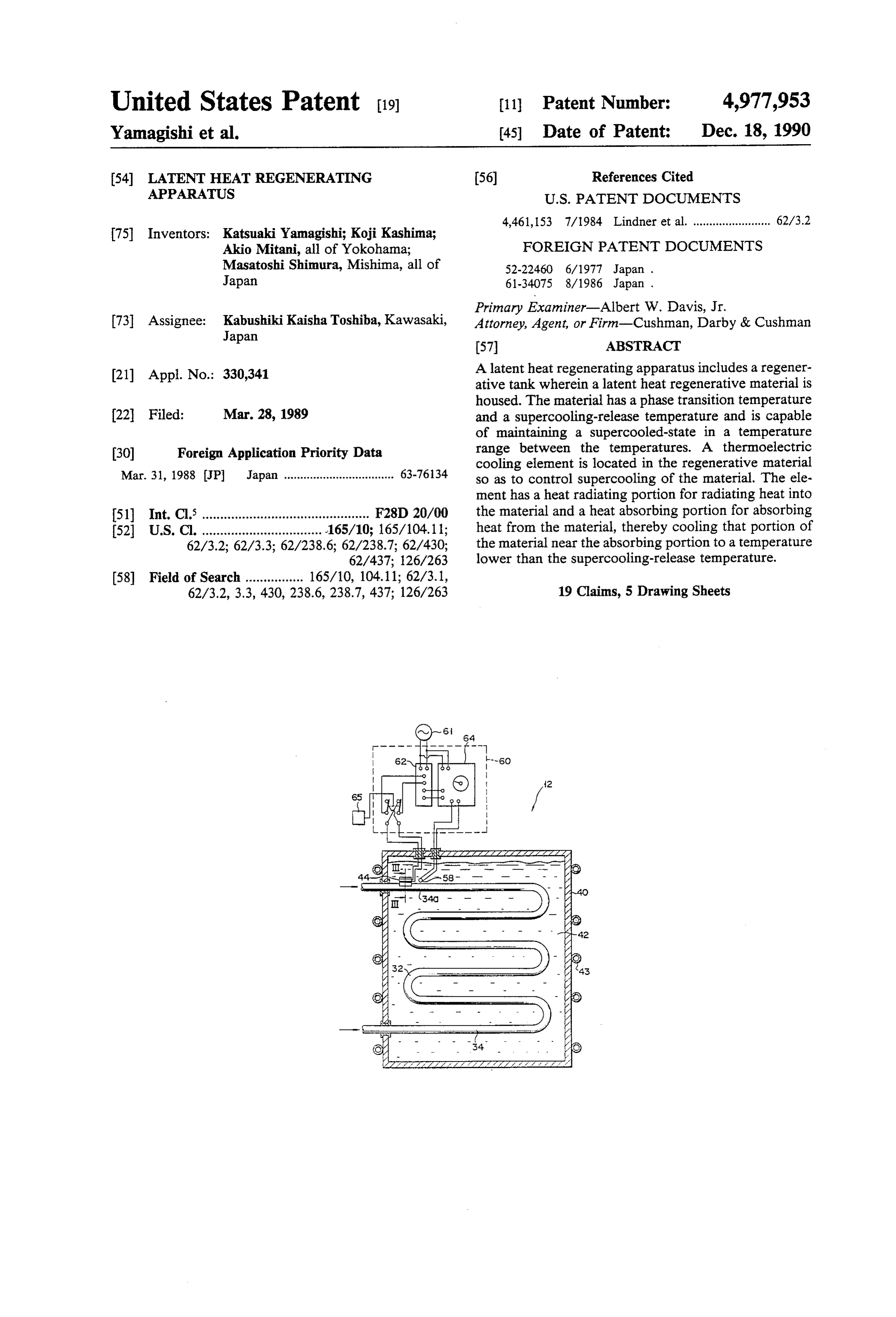
(21) Appl. No.: 330,341 A latent heat regenerating apparatus includes a regener ative tank wherein a latent heat regenerative material is housed. The material has a phase transition temperature 22 Filed: Mar. 28, 1989 and a supercooling-release temperature and is capable of maintaining a supercooled-state in a temperature 30 Foreign Application Priority Data range between the temperatures. A thermoelectric cooling element is located in the regenerative material
Mar. 31, 1988 JP Japan .................................. 63-76134 so as to control supercooling of the material. The ele ment has a heat radiating portion for radiating heat into 51) Int. Cl. .............................................. F28D 20/00 the material and a heat absorbing portion for absorbing 52 U.S. Cl. ................................. 165/10; 165/104.11; heat from the material, thereby cooling that portion of 62/3.2; 62/3.3; 62/238.6; 62/238.7; 62/430; the material near the absorbing portion to a temperature 62/437; 126/263 lower than the supercooling-release temperature.
62/3.2, 3.3, 430, 238.6, 238.7, 437; 126/263 19 Claims, 5 Drawing Sheets
Page 2
Drawing sheet — no readable text.
Page 3
777 ZZNSZZZZZZZZZZZZZZZZZZZ 47
Mitra
=s - 2 4O 2 - 2 - - - - - /- 22Y R
2 -
2 - 2 21 - - N M2 3. - - /. 2 momen as N -91 2
Page 4
Drawing sheet — no readable text.
Page 5
Drawing sheet — no readable text.
Page 6
Drawing sheet — no readable text.
Page 7
piece is cooled below - 12 C. by energizing the
LATENT HEAT REGENERATING APPARATUS thermoelectronic cooling element to cool the piece, it is released from the supercooled state and solidifies imme
Background of the Invention diately. This removal of the supercooled state propa 1. Field of the Invention gates through the wick to the regenerative material in The present invention relates to a latent heat regener the vessel, thus fostering the phase change of the mate ating apparatus. rial. If the regenerative material in the vessel is already 2. Description of the Related Art in the supercooled state, therefore, this state is removed. Recently, there have been provided air conditioners If the material is being cooled from a melted state, it is which combine a refrigeration cycle capable of both 10 prevented from being supercooled, and solidifies imme cooling and heating operations and a regenerating appa diately at the phase transition temperature. However, the regenerating apparatus constructed in ratus. In the air conditioners of this type, heat is accu mulated in a regenerative material of the regenerating thisSince manner has the following problems. apparatus at night. The accumulated heat is used to heat 15 in contactthewith radiation-side metal piece of the element is a refrigerant in heating start operation of the refrigera depending on thethechangeoutside air, its temperature changes of the outside air temperature.
tion cycle, thereby enabling quick start of the heating Also, the cooling temperature of the absorption-side operation. In the cooling operation of the refrigeration metal piece is determined on the basis of the tempera cycle, on the other hand, the heat in the regenerative ture of the radiation-side piece. If the temperature of the material is utilized for cooling the refrigerant, thus im 20 radiation-side piece changes, the cooling temperature of proving the cooling capability of the cycle. the absorption-side piece also changes. Thus, if the A latent heat regenerative material is used as the temperature of the radiation-side metal piece becomes regenerative material of the regenerating apparatus. In very high one day in summer, for example, as the out general, the regenerative material of this type produces side air temperature increases, the cooling temperature the so-called supercooling effect. Thus, once the regen 25 of the absorptionside piece sometimes may not be low erative material is cooled after being heated above its ered below the supercooling-off temperature of the phase transition temperature to be melted, it maintains a regenerative material. In such a case, the regenerative liquid state, without solidifying, even though it is material can neither be released from the supercooled cooled below the phase transition temperature. This is a state nor be prevented from being supercooled. In con supercooled state, which is maintained until the regen 30 sequence, this conventional regenerating apparatus erative material is cooled below a supercooling-off tem lacks reliability.
perature. In such a supercooled state, the latent heat of Further, the phase change of that portion of the re the regenerative material can be utilized for nothing In generative material around the absorption-side metal order to utilize the latent heat accumulated in the regen piece propagates through the wick to the regenerative erative material, or to accumulate the latent heat effi 35 material in the vessel. In this arrangement, however, the ciently in the material, therefore, it is necessary to se speed of propagation of the phase change is lowered by curely remove the supercooled state or prevent the the length of the wick and the like, so that the phase regenerative material from being supercooled. change of the regenerative material in the vessel is sub Thereupon, improved regenerating apparatuses have ject to a delay. Thus, the latent heat of the regenerative recently been developed. These apparatuses are pro material cannot be taken out to be used in a well-timed vided with a supercooling control device for control manner, and the control of the supercooling is difficult. ling the supercooling of the regenerative material. One such apparatus is disclosed in Japanese Patent Publica Summary of the Invention tion No. 61-34075, for example. This apparatus com The present invention has been contrived in consider prises a vessel and a regenerative material therein 45 ation of these circumstances, and its object is to provide adapted for supercooling. In this regenerating appara a latent heat regenerating apparatus, capable of securely tus, moreover, a thermoelectronic cooling element, for preventing a regenerative material from being super use as the supercooling control device, utilizing the cooled, and of releasing the material from a supercooled Peltier effect, is arranged outside the vessel. The ele state, without a time delay.
ment includes a heat radiation-side metal piece and an 50 In order to achieve the above object, according to a absorption-side metal piece, facing each other, and regenerating apparatus according to the present inven p-and n-type semiconductors arranged between the tion, a thermoelectronic refrigerating element of super metal pieces. The absorption-side piece is kept in cooling control means is disposed in a regenerative contact with the regenerative material in the vessel by material in a regenerative tank so that heat radiating and means of a copper rod and a wick (fibrous material). 55 absorbing portions of the element can radiate to and The radiation-side piece is in contact with the outside absorb heat from the regenerative material. Accord 21. ingly, the heat radiating portion of the element can When the element with the aforementioned construc stably cool the heat absorbing portion to a temperature tion is energized, a temperature difference correspond below the supercooling-off temperature of the regener ing to the capacity of the element is caused between the 60 ative material, without being influenced by the outside radiation-and absorption-side metal pieces. In other air temperature. Thus, the regenerative material can be words, the absorption-side piece is cooled to a tempera securely released from a supercooled state or prevented ture lower than that of the radiation-side piece by the from being supercooled. Since the heat absorbing por aforesaid difference. For example, water may be used as tion of the element is located in the regenerative mate the regenerative material. The phase transition tempera 65 rial, moreover, phase change of that portion of the ture and supercooling-off temperature of water are 0 material around the absorbing portion propagates im C. and about - 12 C., respectively. If that portion of mediately to all the regenerative material in the regen the regenerative material around the absorption-side erative tank. In consequence, latent heat can be taken
Page 8
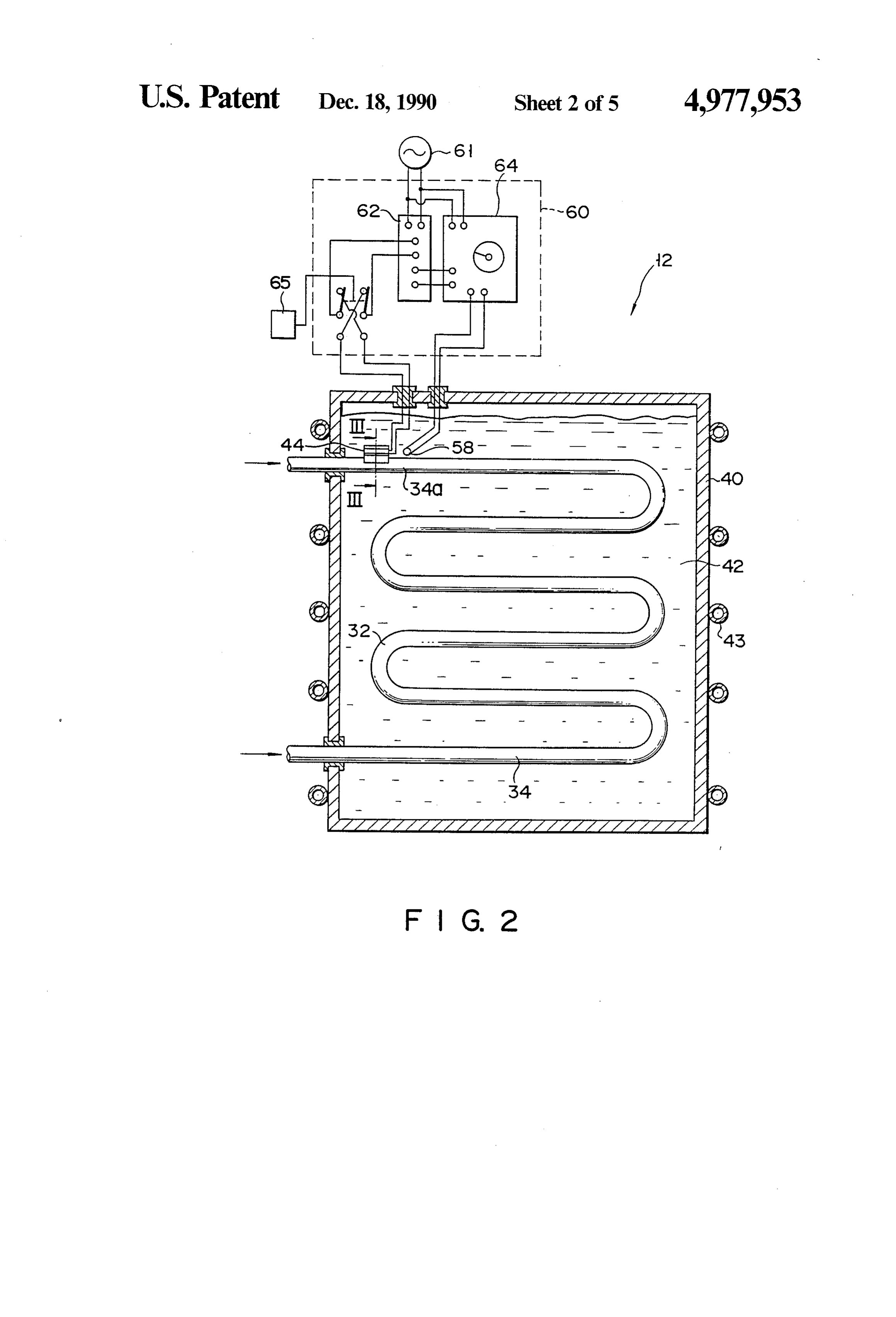
out of the regenerative material without a time delay, Thermoelectronic cooling element 44, which consti and the removal of supercooled state can be controlled tutes part of supercooling control means, is located in with ease. the vicinity of inlet portion 34a of heat exchanger 34, Brief Description of the Drawings inside regenerative tank 40. As is shown in FIG. 3, element 44 is a thermoelectronic cooling element
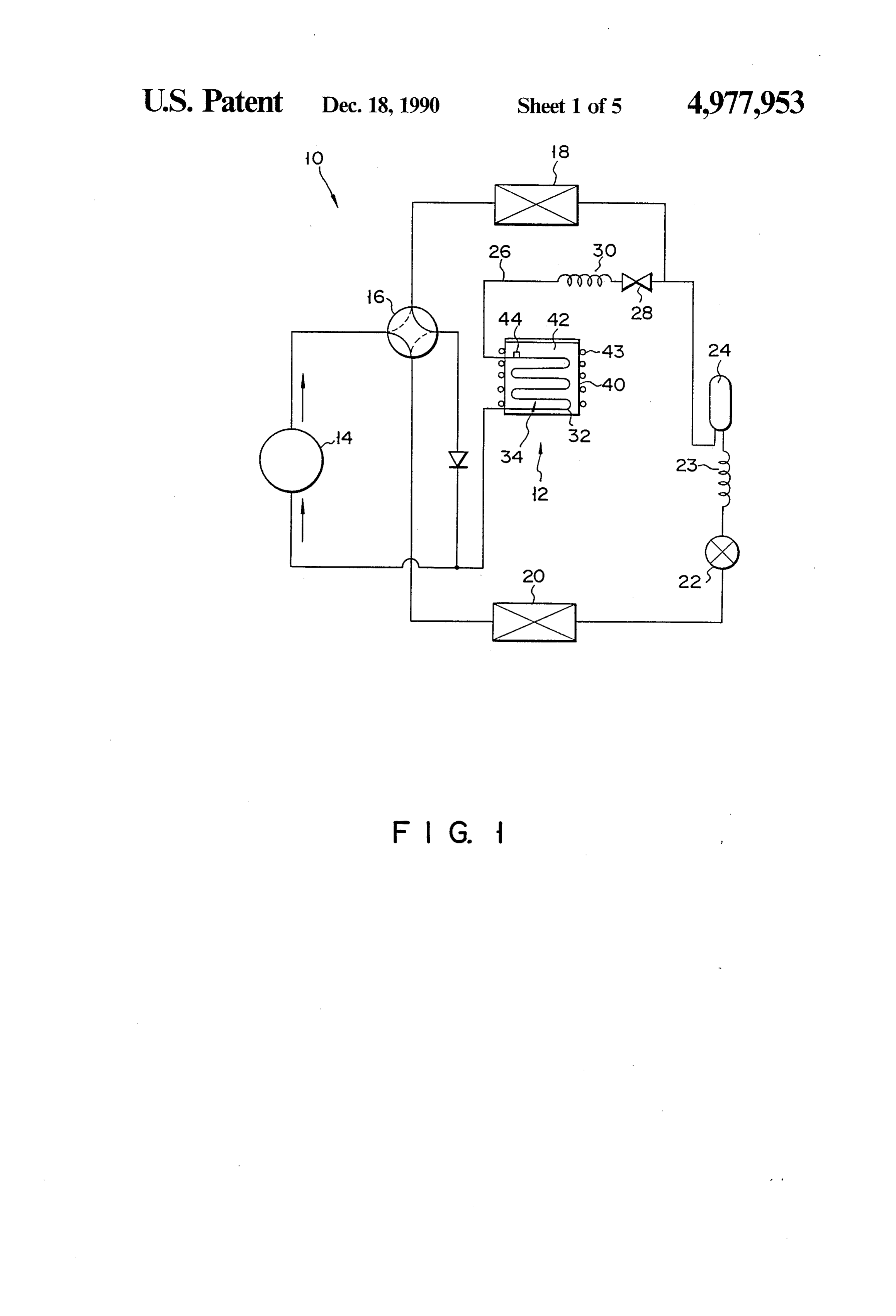
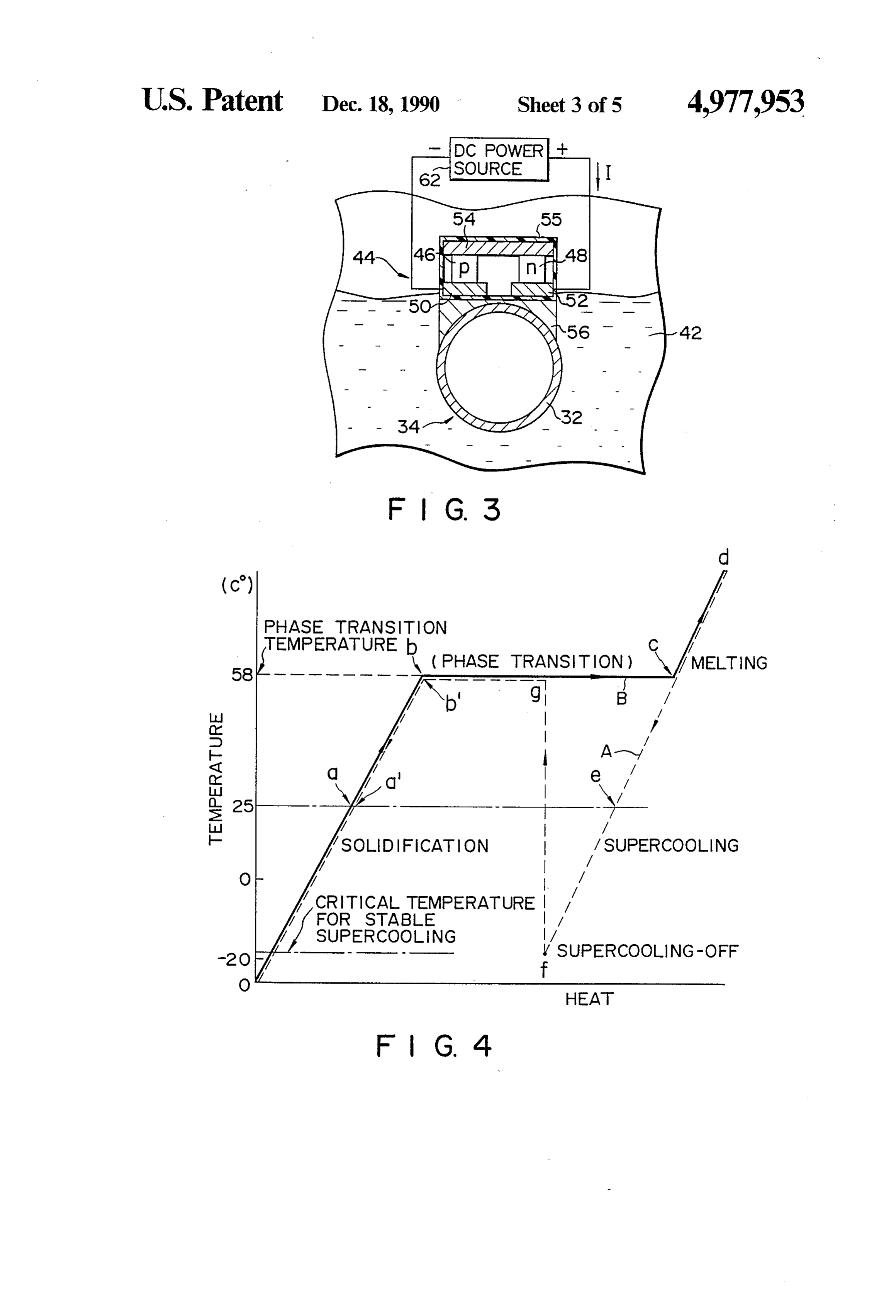
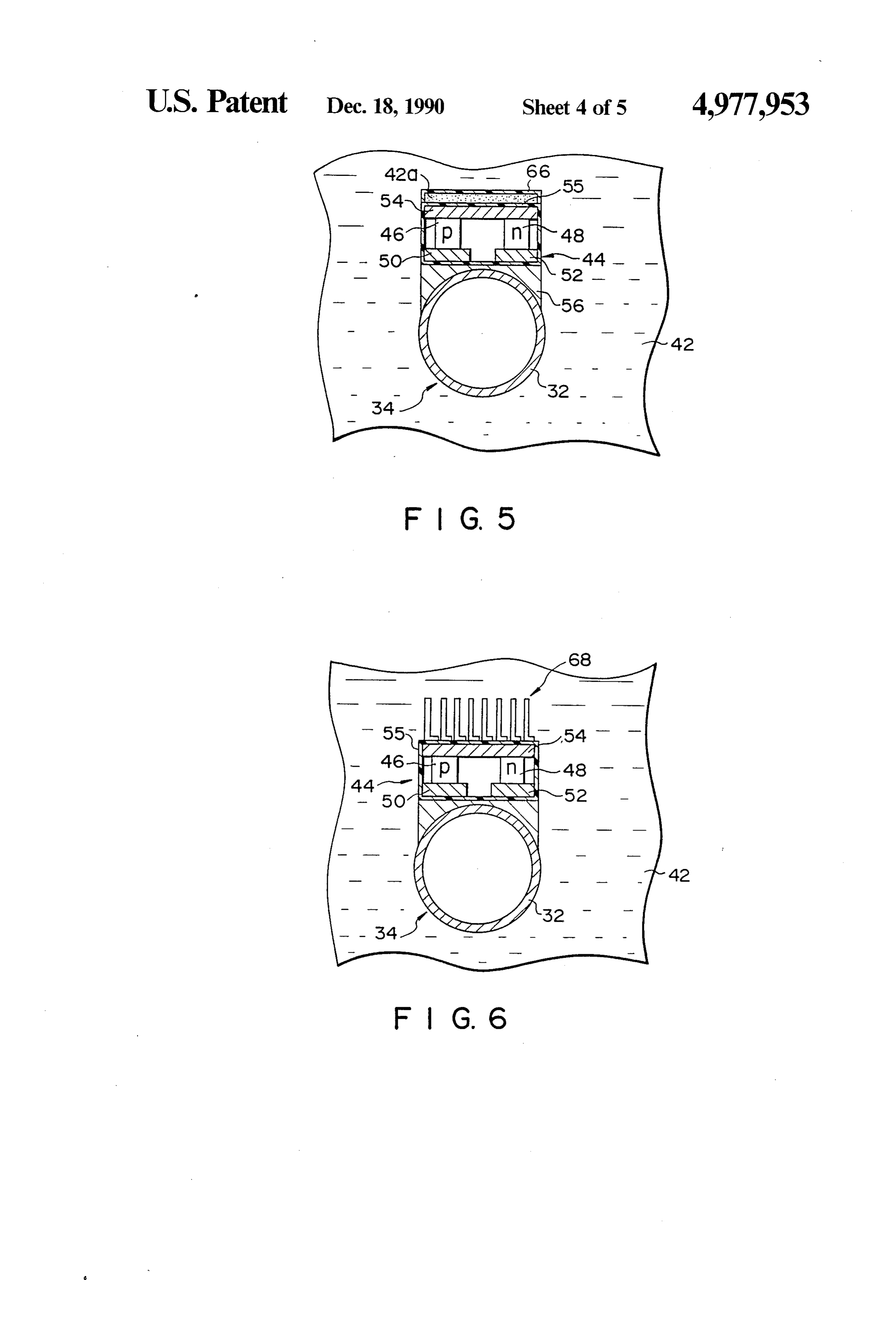
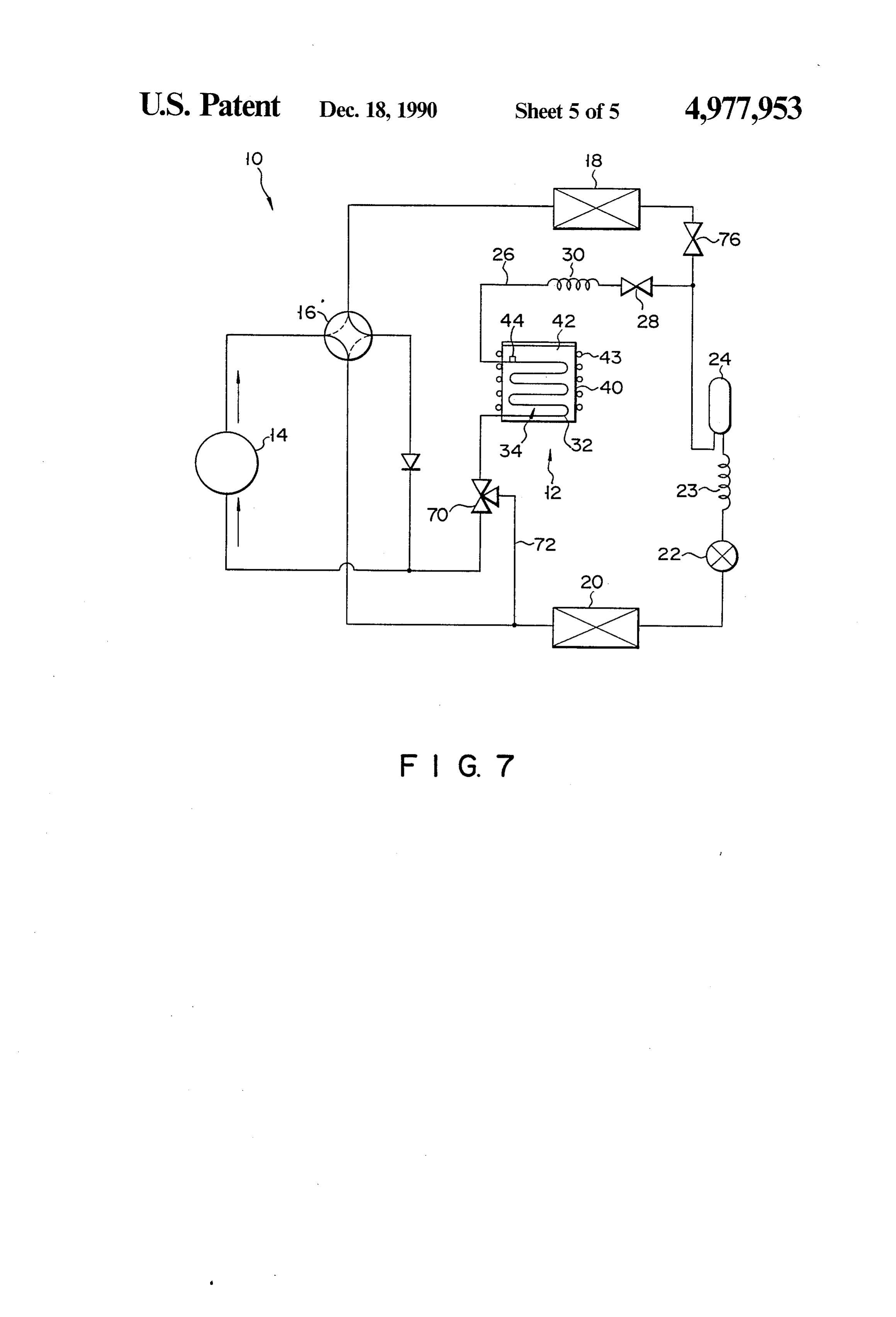
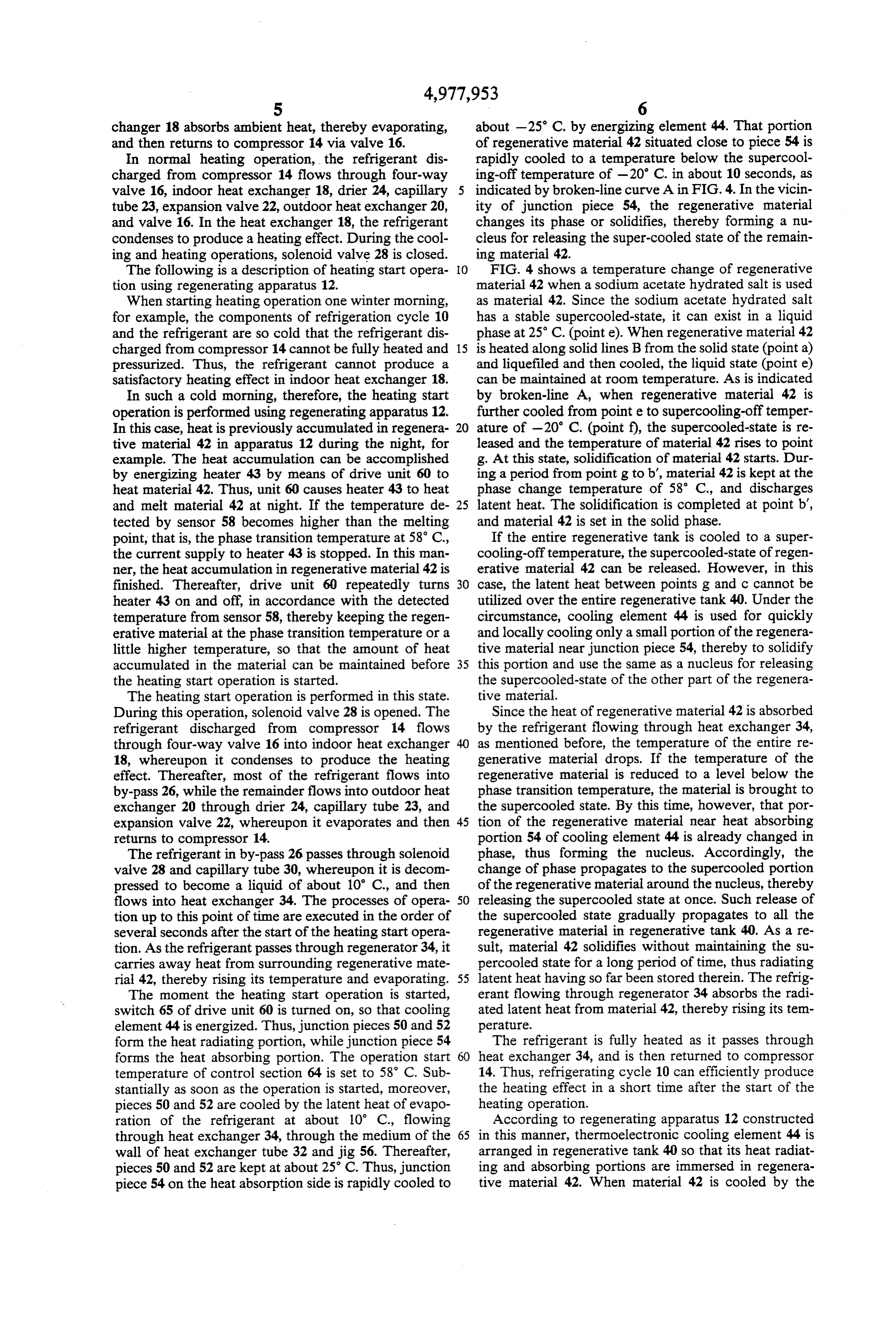
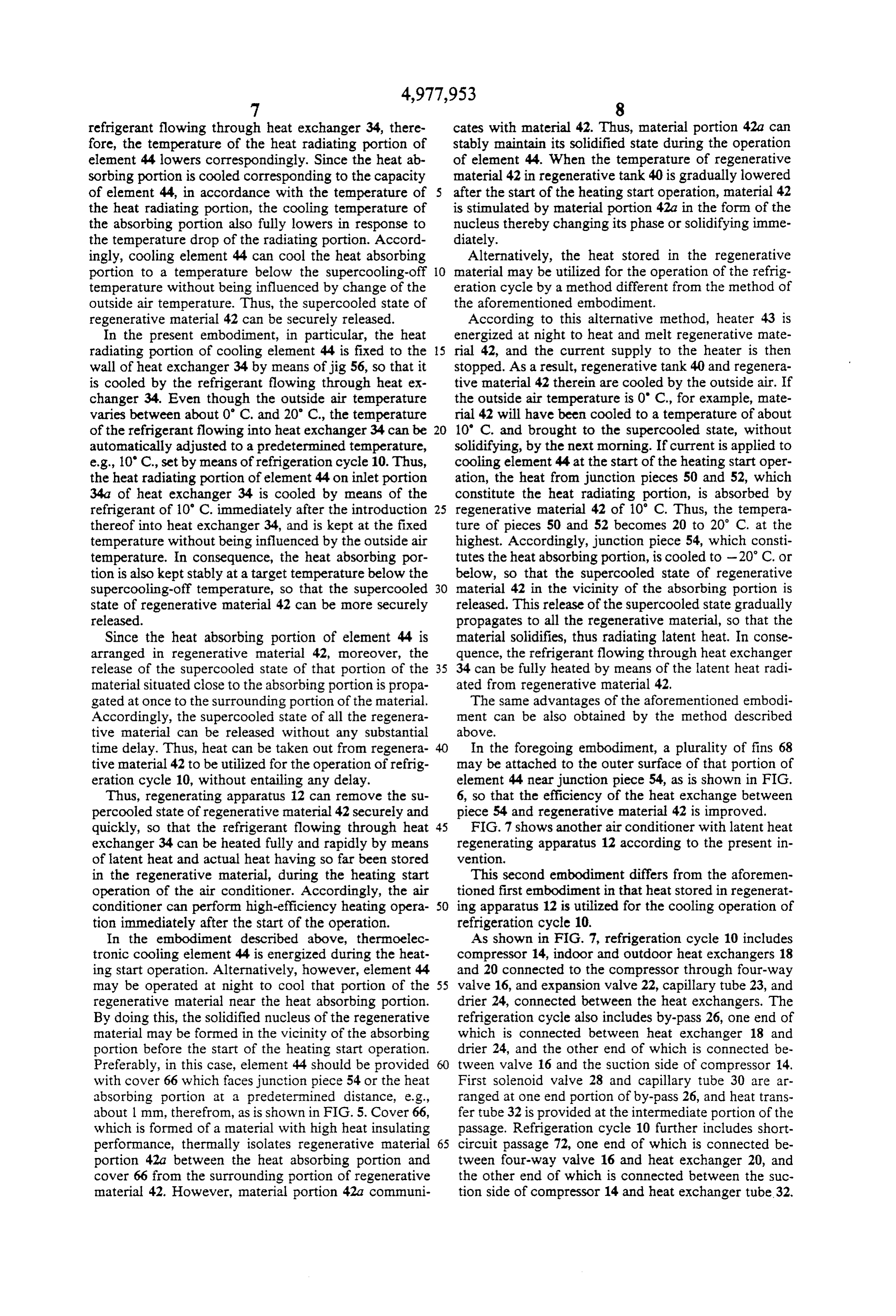
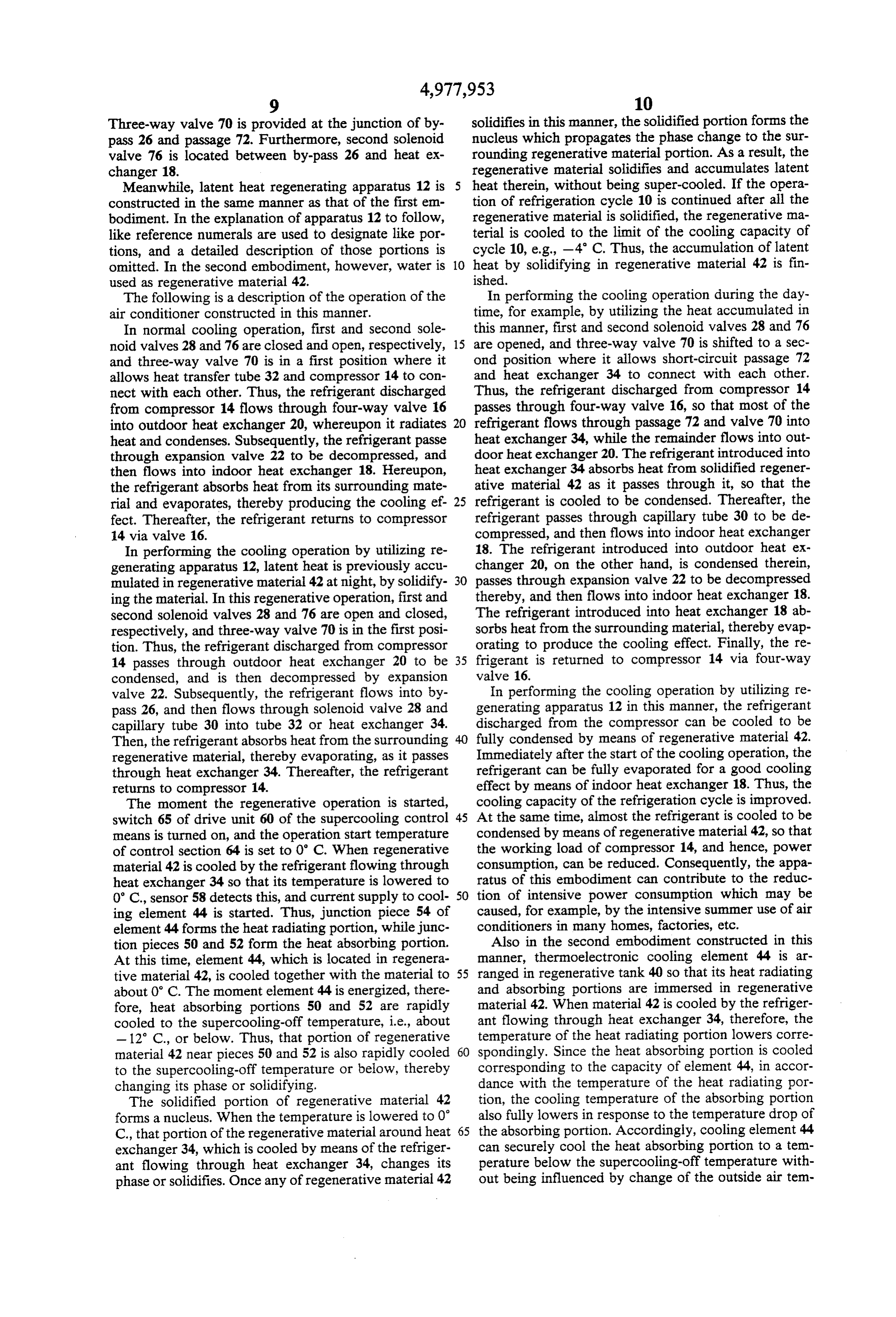
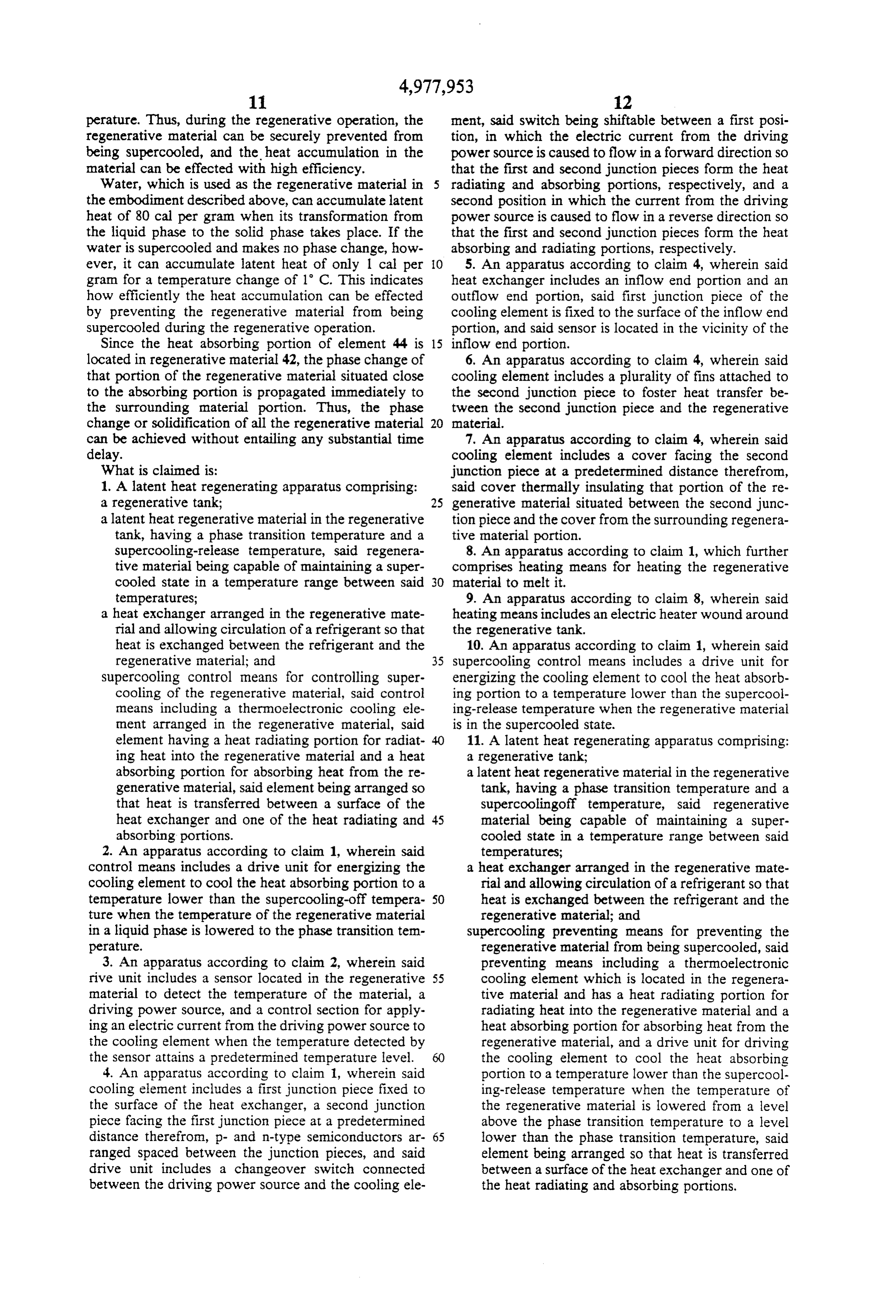
FIGS. 1 to 4 show an air conditioner with a latent which, having p- and n-type semiconductors 46 and 48, heat regenerating apparatus according to an embodi utilizes the Peltier effect. Metallic junction piece 50 is ment of the present invention, in which FIG. 1 is a fixed to one side face of semiconductor 46, while metal diagram schematically showing an outline of the air lic junction piece 52 is fixed to one side face of semicon conditions, FIG. 2 is a sectional view of the regenerat 10 ductor 48. Metallic junction piece 54 is fixed to the ing apparatus, FIG. 3 is a sectional view of a supercool respective other side faces of these semiconductors. The ing control device as taken along line III-III of FIG. 2 whole structure of element 44, constructed in this man and FIG. 4 is a diagram showing the temperature-heat ner, is covered by thin coating film 55 which is formed characteristic of a regenerative material; of an insulator, e.g., epoxy resin. Element 44 is situated FIG. 5 is a sectional view showing a first modifica 15 beside inlet portion 34a of heat exchanger 34 at which tion of the supercooling control device; supercooling is most liable to be caused than at any FIG. 6 is a sectional view showing a second modifica other portions inside regenerative tank 40. Jig 56 is tion of the supercooling control device; and mounted on that side of element 44 on which junction FIG. 7 is a diagram schematically showing an outline 20 pieces 50 and 52 are arranged. At inlet portion 34a, the of an air conditioner with a latent heat regenerating jig is fixed to the outer peripheral surface of heat ex apparatus according to a second embodiment of the changer tube 32 by means of a bonding agent formed of invention. epoxy resin.
Detailed Description of the Preferred Embodiments As is shown in FIG. 2, temperature sensor 58 is lo cated in the vicinity of inlet portion 34a inside regenera
Preferred embodiments of the present invention will 25 tive tank 40. The sensor serves to detect the tempera now be described in detail with reference to the accon ture of regenerative material 42 situated close to portion panying drawing. 34a. Drive unit 60 for driving cooling element 44 is FIG. 1 shows an air conditioner with a regenerative located outside tank 40. Unit 60 includes power source apparatus according to an embodiment of the present section 62 and control section 64 connected thereto. In invention. section 62, AC current from commercial power source As is shown in FIG. 1, the air conditioning apparatus 61 is converted into DC current. Power source section comprises refrigeration cycle 10 and latent heat regen 62 is connected to element 44 through switch 65. Con erating apparatus 12 incorporated therein. The refriger trol section 64 is connected to temperature sensor 58 ation cycle includes compressor 14, four-way valve 16 35 and heater 43.
connected to the discharge and suction sides of the When the temperature of regenerative material 42, compressor, and indoor and outdoor heat exchangers 18 detected by means of sensor 58, reaches a predeter and 20 connected to the four-way valve. Expansion mined level set by means of control section 64 and when valve 22, capillary tube 23, and drier 24 are connected switch 65 is turned on, the control section actuates between heat exchangers 18 and 20. Refrigeration cycle power source section 62, thereby energizing element 44. 10 also includes by-pass 26, one end of which is con As is shown in FIG. 3, the DC current from drive unit nected between indoor heat exchanger 18 and drier 24, 62 flows through junction piece 52, n-type semiconduc and the other end of which connects with the suction tor 48, junction piece 54, p-type semiconductor 46, and side of compressor 14. Solenoid valve 28 and capillary junction piece 50 in the order named. Thus, junction tube 30 are arranged at one end portion of by-pass 26, 45 pieces 50 and 52 form a high-temperature heat radiating and heat transfer tube 32 is provided at the intermediate portion, while junction piece 54, on the other hand, portion of the passage. As is mentioned later, tube 32 is forms a low-temperature heat absorbing portion which located in a regenerative material of regenerating appa produces a cooling effect. Accordingly, regenerative ratus 12, thus constituting heat exchanger 34 for heat material 42 surrounding the heat absorbing portion is accumulation in the regenerative material and heat ab 50 rapidly cooled. In this embodiment, element 44 is capa sorption from the material. ble of producing a temperature difference of 50° C. As is shown in FIGS. 1 and 2, regenerating apparatus between the heat radiating and absorbing portions. 12 comprises regenerative tank 40 with good heat insu By shifting switch 65 to the other position, the DC lating performance, and latent heat regenerative mate current from power source section 62 is caused to flow rial 42 filling the tank. The regenerative material used is 55 in the direction opposite to the case of FIG. 3. There hydrated salt having a phase transition temperature upon, junction piece 54 forms the heat radiating por (melting point) higher than the outside air temperature tion, while junction pieces 50 and 52 form the heat and serving to maintain a supercooled state. For exam absorbing portion to produce the cooling effect. ple, the salt is sodium acetate hydrated salt with a phase The following is a description of the operation of the transition temperature of 58 C. and a supercooling air conditioning apparatus constructed in this manner. release temperature of about -20° C. Heat exchanger First, in cooling operation, the high-temperature, 34 of refrigeration cycle 10 extends through the outer high-pressure refrigerant discharged from compressor wall of regenerative tank 40, and is immersed in regen 14 flows through four-way valve 16 into outdoor heat erative material 42. A refrigerant circulated through exchanger 20, whereupon it radiates heat and con heat exchanger 34 exchanges heat with material 42, 65 denses. Subsequently, the refrigerant flows through thereby heating the material or absorbing heat there expansion valve 22, capillary tube 23, and drier 24 to be from. Sheath heater 43 for heating material 42 is wound decompressed, and then flows into indoor heat ex around the outer surface of tank 40. changer 18. Thereafter, the refrigerant in heat ex
Page 9
changer 18 absorbs ambient heat, thereby evaporating, about -25 C. by energizing element 44. That portion and then returns to compressor 14 via valve 16. of regenerative material 42 situated close to piece 54 is In normal heating operation, the refrigerant dis rapidly cooled to a temperature below the supercool charged from compressor 14 flows through four-way ing-off temperature of -20° C. in about 10 seconds, as valve 16, indoor heat exchanger 18, drier 24, capillary indicated by broken-line curve A in FIG. 4. In the vicin tube 23, expansion valve 22, outdoor heat exchanger 20, ity of junction piece 54, the regenerative material and valve 16. In the heat exchanger 18, the refrigerant changes its phase or solidifies, thereby forming a nu condenses to produce a heating effect. During the cool cleus for releasing the super-cooled state of the remain ing and heating operations, solenoid valve 28 is closed. ing material 42.
The following is a description of heating start opera O FIG. 4 shows a temperature change of regenerative tion using regenerating apparatus 12. material 42 when a sodium acetate hydrated salt is used When starting heating operation one winter morning, as material 42. Since the sodium acetate hydrated salt for example, the components of refrigeration cycle 10 has a stable supercooled-state, it can exist in a liquid and the refrigerant are so cold that the refrigerant dis phase at 25 C. (pointe). When regenerative material 42 charged from compressor 14 cannot be fully heated and 15 is heated along solid lines B from the solid state (point a) pressurized. Thus, the refrigerant cannot produce a and liquefiled and then cooled, the liquid state (point e) satisfactory heating effect in indoor heat exchanger 18. can be maintained at room temperature. As is indicated In such a cold morning, therefore, the heating start by broken-line A, when regenerative material 42 is operation is performed using regenerating apparatus 12. further cooled from point e to supercooling-off temper In this case, heat is previously accumulated in regenera 20 ature of -20 C. (point f), the supercooled-state is re tive material 42 in apparatus 12 during the night, for leased and the temperature of material 42 rises to point example. The heat accumulation can be accomplished g. At this state, solidification of material 42 starts. Dur by energizing heater 43 by means of drive unit 60 to ing a period from point g to b', material 42 is kept at the heat material 42. Thus, unit 60 causes heater 43 to heat phase change temperature of 58 C., and discharges and melt material 42 at night. If the temperature de 25 latent heat. The solidification is completed at point b', tected by sensor 58 becomes higher than the melting and material 42 is set in the solid phase. point, that is, the phase transition temperature at 58 C., If the entire regenerative tank is cooled to a super the current supply to heater 43 is stopped. In this man cooling-off temperature, the supercooled-state of regen ner, the heat accumulation in regenerative material 42 is erative material 42 can be released. However, in this finished. Thereafter, drive unit 60 repeatedly turns 30 case, the latent heat between points g and c cannot be heater 43 on and off, in accordance with the detected utilized over the entire regenerative tank 40. Under the temperature from sensor 58, thereby keeping the regen circumstance, cooling element 44 is used for quickly erative material at the phase transition temperature or a and locally cooling only a small portion of the regenera little higher temperature, so that the amount of heat tive material near junction piece 54, thereby to solidify accumulated in the material can be maintained before 35 this portion and use the same as a nucleus for releasing the heating start operation is started. the supercooled-state of the other part of the regenera The heating start operation is performed in this state. tive material.
During this operation, solenoid valve 28 is opened. The Since the heat of regenerative material 42 is absorbed refrigerant discharged from compressor 14 flows by the refrigerant flowing through heat exchanger 34, through four-way valve 16 into indoor heat exchanger as mentioned before, the temperature of the entire re 18, whereupon it condenses to produce the heating generative material drops. If the temperature of the effect. Thereafter, most of the refrigerant flows into regenerative material is reduced to a level below the by-pass 26, while the remainder flows into outdoor heat phase transition temperature, the material is brought to exchanger 20 through drier 24, capillary tube 23, and the supercooled state. By this time, however, that por expansion valve 22, whereupon it evaporates and then 45 tion of the regenerative material near heat absorbing returns to compressor 14. portion 54 of cooling element 44 is already changed in The refrigerant in by-pass 26 passes through solenoid phase, thus forming the nucleus. Accordingly, the valve 28 and capillary tube 30, whereupon it is decom change of phase propagates to the supercooled portion pressed to become a liquid of about 10 C., and then of the regenerative material around the nucleus, thereby flows into heat exchanger 34. The processes of opera SO releasing the supercooled state at once. Such release of tion up to this point of time are executed in the order of the supercooled state gradually propagates to all the several seconds after the start of the heating start opera regenerative material in regenerative tank 40. As a re tion. As the refrigerant passes through regenerator 34, it sult, material 42 solidifies without maintaining the su carries away heat from surrounding regenerative mate percooled state for a long period of time, thus radiating rial 42, thereby rising its temperature and evaporating. 55 latent heat having so far been stored therein. The refrig The moment the heating start operation is started, erant flowing through regenerator 34 absorbs the radi switch 65 of drive unit 60 is turned on, so that cooling ated latent heat from material 42, thereby rising its tem element 44 is energized. Thus, junction pieces 50 and 52 perature.
form the heat radiating portion, while junction piece 54 The refrigerant is fully heated as it passes through forms the heat absorbing portion. The operation start 60 heat exchanger 34, and is then returned to compressor temperature of control section 64 is set to 58° C. Sub 14. Thus, refrigerating cycle 10 can efficiently produce stantially as soon as the operation is started, moreover, the heating effect in a short time after the start of the pieces 50 and 52 are cooled by the latent heat of evapo heating operation.
ration of the refrigerant at about 10 C., flowing According to regenerating apparatus 12 constructed through heat exchanger 34, through the medium of the 65 in this manner, thermoelectronic cooling element 44 is wall of heat exchanger tube 32 and jig 56. Thereafter, arranged in regenerative tank 40 so that its heat radiat pieces 50 and 52 are kept at about 25 C. Thus, junction ing and absorbing portions are immersed in regenera piece 54 on the heat absorption side is rapidly cooled to tive material 42. When material 42 is cooled by the
Page 10
refrigerant flowing through heat exchanger 34, there cates with material 42. Thus, material portion 42a can fore, the temperature of the heat radiating portion of stably maintain its solidified state during the operation element 44 lowers correspondingly. Since the heat ab of element 44. When the temperature of regenerative Sorbing portion is cooled corresponding to the capacity material 42 in regenerative tank 40 is gradually lowered of element 44, in accordance with the temperature of after the start of the heating start operation, material 42 the heat radiating portion, the cooling temperature of is stimulated by material portion 42a in the form of the the absorbing portion also fully lowers in response to nucleus thereby changing its phase or solidifying imme the temperature drop of the radiating portion. Accord diately.
ingly, cooling element 44 can cool the heat absorbing Alternatively, the heat stored in the regenerative portion to a temperature below the supercooling-off O material may be utilized for the operation of the refrig temperature without being influenced by change of the eration cycle by a method different from the method of outside air temperature. Thus, the supercooled state of the aforementioned embodiment.
regenerative material 42 can be securely released. According to this alternative method, heater 43 is In the present embodiment, in particular, the heat energized at night to heat and melt regenerative mate radiating portion of cooling element 44 is fixed to the 5 rial 42, and the current supply to the heater is then wall of heat exchanger 34 by means of jig 56, so that it stopped. As a result, regenerative tank 40 and regenera is cooled by the refrigerant flowing through heat ex tive material 42 therein are cooled by the outside air. If changer 34. Even though the outside air temperature the outside air temperature is O' C., for example, mate varies between about 0° C. and 20' C., the temperature rial 42 will have been cooled to a temperature of about of the refrigerant flowing into heat exchanger 34 can be 10' C. and brought to the supercooled state, without automatically adjusted to a predetermined temperature, solidifying, by the next morning. If current is applied to e.g., 10' C., set by means of refrigeration cycle 10. Thus, cooling element 44 at the start of the heating start oper the heat radiating portion of element 44 on inlet portion ation, the heat from junction pieces 50 and 52, which 34a of heat exchanger 34 is cooled by means of the constitute the heat radiating portion, is absorbed by refrigerant of 10' C. immediately after the introduction 25 regenerative material 42 of 10° C. Thus, the tempera thereof into heat exchanger 34, and is kept at the fixed ture of pieces 50 and 52 becomes 20 to 20° C. at the temperature without being influenced by the outside air highest. Accordingly, junction piece 54, which consti temperature. In consequence, the heat absorbing por tutes the heat absorbing portion, is cooled to -20°C. or tion is also kept stably at a target temperature below the below, so that the supercooled state of regenerative supercooling-off temperature, so that the supercooled 30 material 42 in the vicinity of the absorbing portion is state of regenerative material 42 can be more securely released. This release of the supercooled state gradually released. propagates to all the regenerative material, so that the Since the heat absorbing portion of element 44 is material solidifies, thus radiating latent heat. In conse arranged in regenerative material 42, moreover, the quence, the refrigerant flowing through heat exchanger release of the supercooled state of that portion of the 35 34 can be fully heated by means of the latent heat radi material situated close to the absorbing portion is propa ated from regenerative material 42. gated at once to the surrounding portion of the material. The same advantages of the aforementioned embodi Accordingly, the supercooled state of all the regenera ment can be also obtained by the method described tive material can be released without any substantial above.
time delay. Thus, heat can be taken out from regenera In the foregoing embodiment, a plurality of fins 68 tive material 42 to be utilized for the operation of refrig may be attached to the outer surface of that portion of eration cycle 10, without entailing any delay. element 44 near junction piece 54, as is shown in FIG. Thus, regenerating apparatus 12 can remove the su 6, so that the efficiency of the heat exchange between percooled state of regenerative material 42 securely and piece 54 and regenerative material 42 is improved. quickly, so that the refrigerant flowing through heat 45 FIG. 7 shows another air conditioner with latent heat exchanger 34 can be heated fully and rapidly by means regenerating apparatus 12 according to the present in of latent heat and actual heat having so far been stored vention.
in the regenerative material, during the heating start This second embodiment differs from the aforemen operation of the air conditioner. Accordingly, the air tioned first embodiment in that heat stored in regenerat conditioner can perform high-efficiency heating opera 50 ing apparatus 12 is utilized for the cooling operation of tion immediately after the start of the operation. refrigeration cycle 10.
In the embodiment described above, thermoelec As shown in FIG. 7, refrigeration cycle 10 includes tronic cooling element 44 is energized during the heat compressor 14, indoor and outdoor heat exchangers 18 ing start operation. Alternatively, however, element 44 and 20 connected to the compressor through four-way may be operated at night to cool that portion of the 55 valve 16, and expansion valve 22, capillary tube 23, and regenerative material near the heat absorbing portion. drier 24, connected between the heat exchangers. The By doing this, the solidified nucleus of the regenerative refrigeration cycle also includes by-pass 26, one end of material may be formed in the vicinity of the absorbing which is connected between heat exchanger 18 and portion before the start of the heating start operation. drier 24, and the other end of which is connected be Preferably, in this case, element 44 should be provided tween valve 16 and the suction side of compressor 14. with cover 66 which faces junction piece 54 or the heat First solenoid valve 28 and capillary tube 30 are ar absorbing portion at a predetermined distance, e.g., ranged at one end portion of by-pass 26, and heat trans about 1 mm, therefrom, as is shown in FIG. 5. Cover 66, fer tube 32 is provided at the intermediate portion of the which is formed of a material with high heat insulating passage. Refrigeration cycle 10 further includes short performance, thermally isolates regenerative material 65 circuit passage 72, one end of which is connected be portion 42a between the heat absorbing portion and tween four-way valve 16 and heat exchanger 20, and cover 66 from the surrounding portion of regenerative the other end of which is connected between the suc material 42. However, material portion 42a communi tion side of compressor 14 and heat exchanger tube. 32.
Page 11
Three-way valve 70 is provided at the junction of by solidifies in this manner, the solidified portion forms the pass 26 and passage 72. Furthermore, second solenoid nucleus which propagates the phase change to the Sur valve 76 is located between by-pass 26 and heat ex rounding regenerative material portion. As a result, the changer 18. regenerative material solidifies and accumulates latent Meanwhile, latent heat regenerating apparatus 12 is heat therein, without being super-cooled. If the opera constructed in the same manner as that of the first em tion of refrigeration cycle 10 is continued after all the bodiment. In the explanation of apparatus 12 to follow, regenerative material is solidified, the regenerative ma like reference numerals are used to designate like por terial is cooled to the limit of the cooling capacity of tions, and a detailed description of those portions is cycle 10, e.g., -4 C. Thus, the accumulation of latent omitted. In the second embodiment, however, water is 10 heat by solidifying in regenerative material 42 is fin used as regenerative material 42. ished.
The following is a description of the operation of the In performing the cooling operation during the day air conditioner constructed in this manner. time, for example, by utilizing the heat accumulated in In normal cooling operation, first and second sole this manner, first and second solenoid valves 28 and 76 noid valves 28 and 76 are closed and open, respectively, 15 are opened, and three-way valve 70 is shifted to a sec and three-way valve 70 is in a first position where it ond position where it allows short-circuit passage 72 allows heat transfer tube 32 and compressor 14 to con and heat exchanger 34 to connect with each other. nect with each other. Thus, the refrigerant discharged Thus, the refrigerant discharged from compressor 14 from compressor 14 flows through four-way valve 16 passes through four-way valve 16, so that most of the into outdoor heat exchanger 20, whereupon it radiates 20 refrigerant flows through passage 72 and valve 70 into heat and condenses. Subsequently, the refrigerant passe heat exchanger 34, while the remainder flows into out through expansion valve 22 to be decompressed, and door heat exchanger 20. The refrigerant introduced into then flows into indoor heat exchanger 18. Hereupon, heat exchanger 34 absorbs heat from solidified regener the refrigerant absorbs heat from its surrounding mate ative material 42 as it passes through it, so that the rial and evaporates, thereby producing the cooling ef 25 refrigerant is cooled to be condensed. Thereafter, the fect. Thereafter, the refrigerant returns to compressor refrigerant passes through capillary tube 30 to be de 14 via valve 16. compressed, and then flows into indoor heat exchanger In performing the cooling operation by utilizing re 18. The refrigerant introduced into outdoor heat ex generating apparatus 12, latent heat is previously accu changer 20, on the other hand, is condensed therein, mulated in regenerative material 42 at night, by solidify 30 passes through expansion valve 22 to be decompressed ing the material. In this regenerative operation, first and thereby, and then flows into indoor heat exchanger 18. second solenoid valves 28 and 76 are open and closed, The refrigerant introduced into heat exchanger 18 ab respectively, and three-way valve 70 is in the first posi sorbs heat from the surrounding material, thereby evap tion. Thus, the refrigerant discharged from compressor orating to produce the cooling effect. Finally, the re 14 passes through outdoor heat exchanger 20 to be 35 frigerant is returned to compressor 14 via four-way condensed, and is then decompressed by expansion valve 16.
valve 22. Subsequently, the refrigerant flows into by In performing the cooling operation by utilizing re pass 26, and then flows through solenoid valve 28 and generating apparatus 12 in this manner, the refrigerant capillary tube 30 into tube 32 or heat exchanger 34. discharged from the compressor can be cooled to be Then, the refrigerant absorbs heat from the surrounding fully condensed by means of regenerative material 42. regenerative material, thereby evaporating, as it passes Immediately after the start of the cooling operation, the through heat exchanger 34. Thereafter, the refrigerant refrigerant can be fully evaporated for a good cooling returns to compressor 14. effect by means of indoor heat exchanger 18. Thus, the The moment the regenerative operation is started, cooling capacity of the refrigeration cycle is improved. switch 65 of drive unit 60 of the supercooling control 45 At the same time, almost the refrigerant is cooled to be means is turned on, and the operation start temperature condensed by means of regenerative material 42, so that of control section 64 is set to O' C. When regenerative the working load of compressor 14, and hence, power material 42 is cooled by the refrigerant flowing through consumption, can be reduced. Consequently, the appa heat exchanger 34 so that its temperature is lowered to ratus of this embodiment can contribute to the reduc O' C., sensor 58 detects this, and current supply to cool 50 tion of intensive power consumption which may be ing element 44 is started. Thus, junction piece 54 of caused, for example, by the intensive summer use of air element 44 forms the heat radiating portion, while junc conditioners in many homes, factories, etc. tion pieces 50 and 52 form the heat absorbing portion. Also in the second embodiment constructed in this At this time, element 44, which is located in regenera manner, thermoelectronic cooling element 44 is ar tive material 42, is cooled together with the material to 55 ranged in regenerative tank 40 so that its heat radiating about 0°C. The moment element 44 is energized, there and absorbing portions are immersed in regenerative fore, heat absorbing portions 50 and 52 are rapidly material 42. When material 42 is cooled by the refriger cooled to the supercooling-off temperature, i.e., about ant flowing through heat exchanger 34, therefore, the - 12 C., or below. Thus, that portion of regenerative temperature of the heat radiating portion lowers corre material 42 near pieces 50 and 52 is also rapidly cooled 60 spondingly. Since the heat absorbing portion is cooled to the supercooling-off temperature or below, thereby corresponding to the capacity of element 44, in accor changing its phase or solidifying. dance with the temperature of the heat radiating por The solidified portion of regenerative material 42 tion, the cooling temperature of the absorbing portion forms a nucleus. When the temperature is lowered to 0 also fully lowers in response to the temperature drop of C., that portion of the regenerative material around heat 65 the absorbing portion. Accordingly, cooling element 44 exchanger 34, which is cooled by means of the refriger can securely cool the heat absorbing portion to a tem ant flowing through heat exchanger 34, changes its perature below the supercooling-off temperature with phase or solidifies. Once any of regenerative material 42 out being influenced by change of the outside air tem
Page 12
perature. Thus, during the regenerative operation, the ment, said switch being shiftable between a first posi regenerative material can be securely prevented from tion, in which the electric current from the driving being supercooled, and the heat accumulation in the power source is caused to flow in a forward direction so material can be effected with high efficiency. that the first and second junction pieces form the heat Water, which is used as the regenerative material in 5 radiating and absorbing portions, respectively, and a the embodiment described above, can accumulate latent second position in which the current from the driving heat of 80 cal per gram when its transformation from power source is caused to flow in a reverse direction so the liquid phase to the solid phase takes place. If the that the first and second junction pieces form the heat water is supercooled and makes no phase change, how absorbing and radiating portions, respectively. ever, it can accumulate latent heat of only 1 cal per 10 5. An apparatus according to claim 4, wherein said gram for a temperature change of 1 C. This indicates heat exchanger includes an inflow end portion and an how efficiently the heat accumulation can be effected outflow end portion, said first junction piece of the by preventing the regenerative material from being cooling element is fixed to the surface of the inflow end supercooled during the regenerative operation. portion, and said sensor is located in the vicinity of the Since the heat absorbing portion of element 44 is 15 inflow end portion.
located in regenerative material 42, the phase change of 6. An apparatus according to claim 4, wherein said that portion of the regenerative material situated close cooling element includes a plurality of fins attached to to the absorbing portion is propagated immediately to the second junction piece to foster heat transfer be the surrounding material portion. Thus, the phase tween the second junction piece and the regenerative change or solidification of all the regenerative material 20 material.
can be achieved without entailing any substantial time 7. An apparatus according to claim 4, wherein said delay. cooling element includes a cover facing the second What is claimed is: junction piece at a predetermined distance therefrom, 1. A latent heat regenerating apparatus comprising: said cover thermally insulating that portion of the re a regenerative tank; 25 generative material situated between the second junc a latent heat regenerative material in the regenerative tion piece and the cover from the surrounding regenera tank, having a phase transition temperature and a tive material portion.
Supercooling-release temperature, said regenera 8. An apparatus according to claim 1, which further tive material being capable of maintaining a super comprises heating means for heating the regenerative cooled state in a temperature range between said 30 material to melt it.
temperatures; 9. An apparatus according to claim 8, wherein said a heat exchanger arranged in the regenerative mate heating means includes an electric heater wound around rial and allowing circulation of a refrigerant so that the regenerative tank.
heat is exchanged between the refrigerant and the 10. An apparatus according to claim 1, wherein said regenerative material; and 35 Supercooling control means includes a drive unit for Supercooling control means for controlling super energizing the cooling element to cool the heat absorb cooling of the regenerative material, said control ing portion to a temperature lower than the supercool means including a thermoelectronic cooling ele ing-release temperature when the regenerative material ment arranged in the regenerative material, said is in the supercooled state.
element having a heat radiating portion for radiat- 40 11. A latent heat regenerating apparatus comprising: ing heat into the regenerative material and a heat a regenerative tank;
absorbing portion for absorbing heat from the re a latent heat regenerative material in the regenerative generative material, said element being arranged so tank, having a phase transition temperature and a that heat is transferred between a surface of the supercoolingoff temperature, said regenerative heat exchanger and one of the heat radiating and 45 material being capable of maintaining a super absorbing portions. cooled state in a temperature range between said 2. An apparatus according to claim 1, wherein said temperatures;
control means includes a drive unit for energizing the a heat exchanger arranged in the regenerative mate cooling element to cool the heat absorbing portion to a rial and allowing circulation of a refrigerant so that temperature lower than the supercooling-off tempera- 50 heat is exchanged between the refrigerant and the ture when the temperature of the regenerative material regenerative material; and in a liquid phase is lowered to the phase transition tem supercooling preventing means for preventing the perature. regenerative material from being supercooled, said 3. An apparatus according to claim 2, wherein said preventing means including a thermoelectronic rive unit includes a sensor located in the regenerative 55 cooling element which is located in the regenera material to detect the temperature of the material, a tive material and has a heat radiating portion for driving power source, and a control section for apply radiating heat into the regenerative material and a ing an electric current from the driving power source to heat absorbing portion for absorbing heat from the the cooling element when the temperature detected by regenerative material, and a drive unit for driving the sensor attains a predetermined temperature level. 60 the cooling element to cool the heat absorbing 4. An apparatus according to claim 1, wherein said portion to a temperature lower than the supercool cooling element includes a first junction piece fixed to ing-release temperature when the temperature of the surface of the heat exchanger, a second junction the regenerative material is lowered from a level piece facing the first junction piece at a predetermined above the phase transition temperature to a level distance therefron, p- and n-type semiconductors ar- 65 lower than the phase transition temperature, said ranged spaced between the junction pieces, and said element being arranged so that heat is transferred drive unit includes a changeover switch connected between a surface of the heat exchanger and one of between the driving power source and the cooling ele the heat radiating and absorbing portions.
Page 13
12. A latent heat regenerating apparatus comprising: tion side of the compressor, said heat exchanger being a regenerative tank; provided in the by-pass, and valve means for regulating a latent heat regenerative material in the regenerative the flow of the refrigerant so that the refrigerant dis tank, having a phase transition temperature and a charge rom the indoor heat exchanger, at the start of supercoolingrelease temperature, said regenerative the heating operation, flows into the by-pass absorbs material being capable of maintaining a super heat from the regenerative material, thereby increasing cooled state in a temperature range between said the temperature of the refrigerant, as the refrigerant temperatures; passes through the heat exchanger, and then return to a heat exchanger arranged in the regenerative mate the compressor.
rial and allowing circulation of a refrigerant so that 10 15. An air conditioner according to claim 14, wherein heat is exchanged between the refrigerant and the said supercooling control means includes a drive unit regenerative material; and for driving the cooling element to cool the heat absorb supercooling release means for releasing the super ing portion to a temperature lower than the supercool cooled state of the regenerative material, said re ing-release temperature when the temperature of the lease means including a thermoelectronic cooling 5 regenerative material is lowered from a level above the element located in the regenerative material and phase transition temperature to a level lower than the having a heat radiating portion for radiating heat phase transition temperature, at the start of the heating into the regenerative material and a heat absorbing operation, so that the regenerative material is prevented portion for absorbing heat from the regenerative from being supercooled.
material, and a drive unit for driving the electronic 20 16. An air conditioner according to claim 14, wherein refrigerating element to cool the heat absorbing said supercooling control means includes a drive unit portion to a temperature lower than the supercool for driving the cooling element to cool the heat absorb ing release temperature when the regenerative ing portion to a temperature lower than the supercool material is in the supercooled state, said element ing-release temperature when the regenerative material being arranged so that heat is transferred between 25 is in the supercooled state, at the start of the heating a surface of the heat exchanger and one of the heat operation, so that the supercooled state of the regenera radiating and absorbing portions. tive material is released.
13. An air conditioner, comprising: 17. An air conditioner according to claim 13, wherein a refrigeration cycle capable of cooling and heating said regenerating apparatus includes means for heating operations, said refrigeration cycle including a 30 the regenerative material to melt it. compressor, a four-way valve connected to dis 18. An air conditioner according to claim 13, wherein charge and suction sides of the compressor, an said refrigerating cycle includes a by-pass having one indoor heat exchanger connected to the fourway end connected between the indoor and outdoor heat valve, and outdoor heat exchanger connected to exchangers and the other end connecting with the suc the four-way valve, and pressure reducing means 35 tion side of the compressor, a heat exchanger provided connected between the heat exchangers; and in the by-pass and located in the regenerative material a latent heat regenerating apparatus including a re of the regenerating apparatus, a short-circuit passage generative tank, a latent heat regenerative material having one end connected between the heat exchanger in the regenerative tank, having a phase transition and the suction side of the compressor and the other end temperature and a supercooling-release tempera 40 connected between the four-way valve and the outdoor ture, said regenerative material being capable of heat exchanger, and valve means for regulating the flow maintaining a supercooled state in a temperature of the refrigerant so that the refrigerant discharged range between said temperatures, a heat exchanger from the outdoor heat exchanger flows into the by-pass, arranged in the regenerative material and allowing absorbs heat from the regenerative material, thereby circulation of a refrigerant so that heat is ex 45 cooling the regenerative material, as the refrigerant changed between the refrigerant and the regenera passes through the heat exchanger, and then returns to tive material, and supercooling control means for the compressor, and that the refrigerant discharged controlling supercooling of the regenerative mate from the compressor, at the start of the cooling opera rial, said control means including a thermoelec tion, flows through the short-circuit passage and the tronic cooling element located in the regenerative 50 by-pass, is cooled to be condensed by the regenerative material, said element having a heat radiating por material as the refrigerant passes through the heat ex tion for radiating heat into the regenerative mate changer, and then flows into the indoor heat exchanger. rial and a heat absorbing portion for absorbing heat 19. The apparatus according to claim 18, wherein said from the regenerative material, said element being supercooling control means includes a drive unit for arranged so that heat is transferred between a sur 55 driving the cooling element to cool the heat absorbing face of the heat exchanger and one of the heat portion to a temperature lower than the supercooling radiating and absorbing portions, whereby the heat release temperature when the temperature of the regen accumulated in the regenerative material is sup erative material is lowered from a level above the phase plied to a refrigerant flowing through the refriger transition temperature to a level lower than the phase ating cycle. 60 transition temperature, as the regenerative material is 14. An air conditioner according to claim 13, wherein cooled by the refrigerant flowing through the heat said refrigeration cycle includes a by-pass having one exchanger, so that the regenerative material is pre end connected between the indoor and outdoor heat vented from being supercooled.
exchangers and another end connecting with the suc
Provenance
- Collection
- Cited prior art
- Original PDF
- patentimages.storage.googleapis.com →
- Filed
- 1989-03-28
- Pages
- 13
- Method
- pdftotext (the PDF's own text layer) + pdftoppm 300dpi page scans
- Source
- Google Patents bibliographic record
- Granted
- 1990-12-18
- Inventors
- Katsuaki Yamagishi; Koji Kashima; Akio Mitani; Masatoshi Shimura; Toshiba Corp
- Transcribed from
- patentimages.storage.googleapis.com →