patent · US5598712
Latent heat accumulation system
4 February 1997
Page 1 — bibliographic record
United States Patent 19) 11 Patent Number:
Watanabe et al. 5,598,712 (45) Date of Patent: Feb. 4, 1997 54) LATENT HEAT ACCUMULATION SYSTEM 1-203832 8/1989 Japan ......................................... 62/59 75 Inventors: Yutaka Watanabe, Takayuki 1-244225 9/1989 Japan ......................................... 62/59 Hachimonji, both of Yokohama; 3-59335 3/1991 Japan ......................................... 62A59 0.129228 6/1991 Japan ......................................... 62/59
Katsuya Yamashita; Sanae Sekita, both of Tokyo; Tsuyoshi Noma, OTHER PUBLICATIONS
Yokohama, all of Japan Proceedings of The 2nd International Conference on Mul 73) Assignee: Kabushiki Kaisha Toshiba, Kawasaki, tiphase Flow 95-Kyoto, Apr. 3–7, 1995, vol. 3, "Experi Japan mental Study on Frazil Ice Formation and Characteristics of Direct Heat Transfer Between Two Liquids', by Y.
21 Appl. No.: 518,580 Watanabe, et al., pp. EN25-EN31. 22 Filed: Aug. 15, 1995 Primary Examiner-John Rivell
Assistant Examiner-Christopher Atkinson
Related U.S. Application Data Attorney, Agent, or Firm-Oblon, Spivak, McClelland, Maier & Neustadt, P.C.
63 Continuation-in-part of Ser. No. 417,470, Apr. 5, 1995, Pat. (57) ABSTRACT No. 5,481,882, which is a continuation of Ser. No. 22,556,
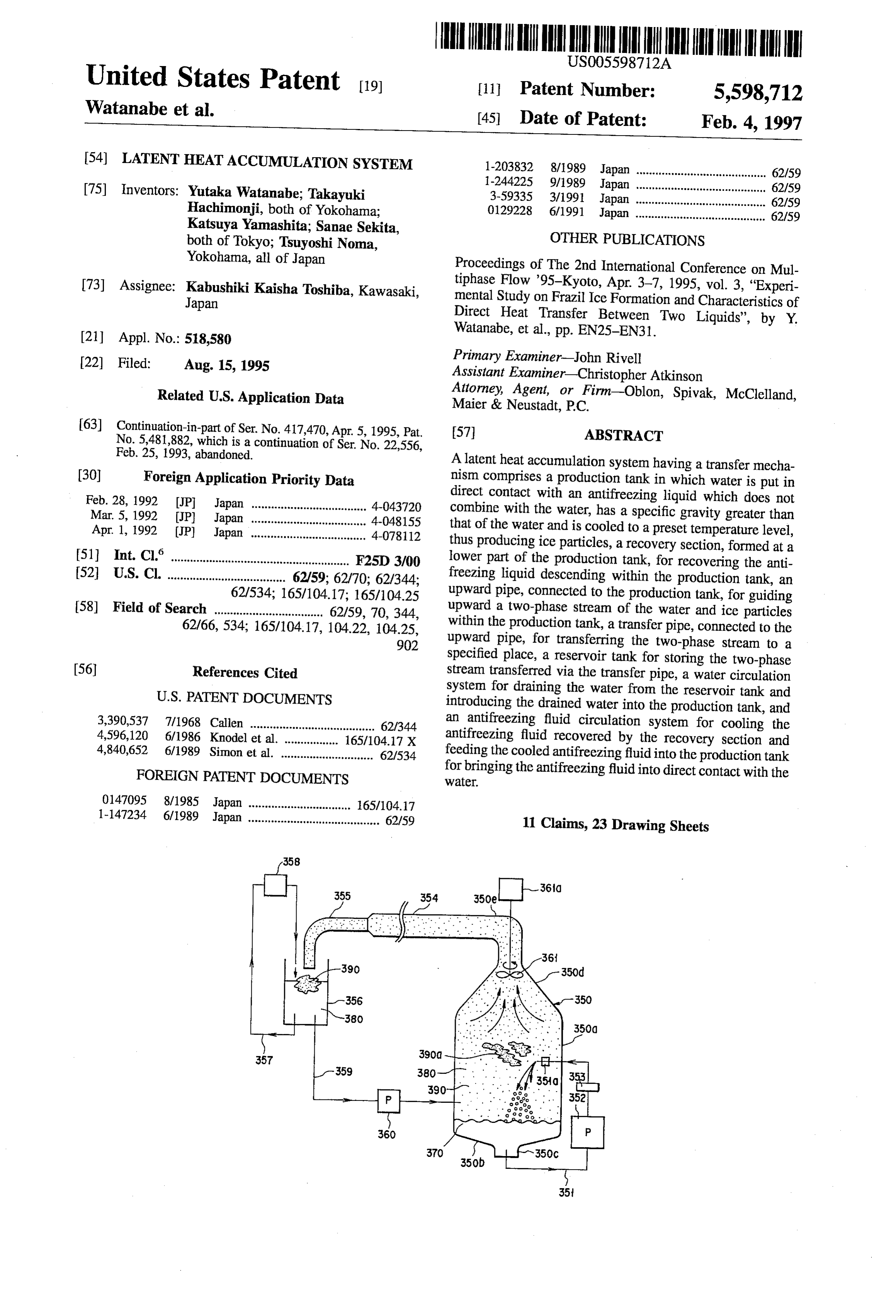
A latent heat accumulation system having a transfer mecha (30) Foreign Application Priority Data nism comprises a production tank in which water is put in Feb. 28, 1992 JP Japan .................................... 4-043720 direct contact with an antifreezing liquid which does not Mar. 5, 1992 (JP) Japan .................................... 4-048155 combine with the water, has a specific gravity greater than Apr. 1, 1992 (JP) Japan .................................... 4-078112 that of the water and is cooled to a preset temperature level, thus producing ice particles, a recovery section, formed at a (51) Int. Cl." ................... F2SD 3/00 lower part of the production tank, for recovering the anti 52 U.S. Cl. ..................................... 62/59; 62/70; 62/344; freezing liquid descending within the production tank, an 62/534; 165/104.17; 165/104.25 upward pipe, connected to the production tank, for guiding 58) Field of Search .................................. 62/59, 70,344, upward a two-phase stream of the water and ice particles 62/66, 534; 165/104.17, 10422, 104.25, within the production tank, a transfer pipe, connected to the 902 upward pipe, for transferring the two-phase stream to a specified place, a reservoir tank for storing the two-phase (56) References Cited stream transferred via the transfer pipe, a water circulation
introducing the drained water into the production tank, and 3,390,537 7/1968 Callen ....................................... 62/344 an antifreezing fluid circulation system for cooling the 4,596,120 6/1986 Knodel et al. ...... ... 165/104.17 X antifreezing fluid recovered by the recovery section and 4,840,652 6/1989 Simon et al. ............................. 62/534 feeding the cooled antifreezing fluid into the production tank FOREIGN PATENT DOCUMENTS for bringing the antifreezing fluid into direct contact with the Water.
0.147095 8/1985 Japan ................................ 65/104.17 1-147234 6/1989 Japan ......................................... 62/59 11 Claims, 23 Drawing Sheets
Page 2
Drawing sheet — no readable text.
Page 3
Drawing sheet — no readable text.
Page 4
Drawing sheet — no readable text.
Page 5
Drawing sheet — no readable text.
Page 6
Drawing sheet — no readable text.
Page 7
Drawing sheet — no readable text.
Page 8
Drawing sheet — no readable text.
Page 9
Drawing sheet — no readable text.
Page 10
Drawing sheet — no readable text.
Page 11
Drawing sheet — no readable text.
Page 12
Drawing sheet — no readable text.
Page 13
Drawing sheet — no readable text.
Page 14
Drawing sheet — no readable text.
Page 15
Drawing sheet — no readable text.
Page 16
Drawing sheet — no readable text.
Page 17
Drawing sheet — no readable text.
Page 18
Drawing sheet — no readable text.
Page 19
Drawing sheet — no readable text.
Page 20
Drawing sheet — no readable text.
Page 21
Drawing sheet — no readable text.
Page 22
Drawing sheet — no readable text.
Page 23
Drawing sheet — no readable text.
Page 24
Drawing sheet — no readable text.
Page 25
LATENT HEAT ACCUMULATION SYSTEM The latent heat accumulation system shown in FIG. 2 includes an ice making container 20A, heat storage tank
CROSS-REFERENCE TO THE RELATED
20B, water 200, oil 20D having a small specific gravity, oil 20E having a large specific gravity, ice 20F, communicating
APPLICATIONS pipe 200, pump 20H, refrigerator 20I, small-specific-gravity oil circulating pipe 20, small-specific-gravity oil returnpipe
This application is a continuation-in-part of U.S. patent 20K, water return pipe 20L, float 20M, pump 20N and the application Ser. No. 08/417,470, filed Apr. 5, 1995 now U.S. like.
Pat. No. 5,481,882 which is a continuation application of application No. 08/022,556 filed Feb. 25, 1993, now aban 10 andIn2,thewater latent heat accumulation system shown in FIGS. 1 is used as the first liquid and an oily liquid doned.
which is lighter than water is used as the second liquid. The second liquid which is cooled by the refrigerator is fed via
BACKGROUND OF THE INVENTION the pump and pipe and injected into water stored in the 1. Field of the Invention bottom portion of the water reservoir. 5 However, with the above structure, since the density of
This invention relates to a latent heat accumulation sys the second liquid which is a non-freezing liquid is almost the tem which can be suitably used in an air-conditioning same as that of water or the second liquid is lighter than equipment disposed in a multistoried building, industrial water, the oily liquid will be mixed into the ice made in the plant, or large-scale regional heat supplying plant. sherbet state. As a result, it becomes difficult to draw out 2. Description of the Related Art 20 cold water directly from the water tank and supply the cold Recently, it is proposed to use a heat accumulation type water to the cooling load. Further, it becomes necessary to air-conditioning system for creating a latent heat accumu use a cold transferring heat exchanger in order to transfer the lation medium such as cold water or hot water by driving a cold from the water tank. Therefore, the requirements for heat pump (refrigerator) by utilizing cheap electric power drawing out the cold in a short period of time, making the during the nighttime hours and mainly using the latent heat 25 construction of the device simple and directly drawing out accumulation medium for an air-conditioning system for water cannot be met to a full satisfaction.
cooling during the daytime hours. The air-conditioning As a latent heat accumulation system made for solving the system is an economically improved air-conditioning equip above problem, a system shown in FIG. 3 cited from ment and can be suitably used as an air-conditioning equip Japanese Patent Disclosure No. 56-25664 is proposed, for ment disposed in a multistoried building, industrial plant, or 30 example. The latent heat accumulation system shown in large-scale regional heat supplying plant. Further, in recent FIG. 3 includes a water tank 30A, water 30B, oil 30C, oil years, the cooling load in the daytime hours in summer is supplying device 30D, separation film 30E, return port 30F rapidly increasing. Therefore, stable supply of electric for circulating water, pump 30G, refrigerator 30H, outlet power cannot sometimes be attained. The above air-condi port 30I for cold water and the like. tioning system which can reduce the electric power con 35 In the latent heat accumulation system of FIG. 3, a first sumption in the daytime hours is of great importance in the liquid (water) is stored in the water tank. A second liquid stable supply of electric power. (which is an oily liquid and is lighter than water and ice) is This type of heat accumulation system using ice is gen injected from the bottom portion of the water tank into the erally used for air conditioning. This type of heat accumu first liquid in the upward direction. The second liquid is lation system utilizes water as a latent heat accumulation cooled to a temperature lower than the freezing or solidify medium (first liquid). The water is used to continuously ing point of the first liquid (water) by the refrigerator. Thus, make sherbet-state ice with high efficiency. That is, a heat heat exchange occurs when the second liquid is brought into accumulation refrigerant (second liquid) cooled to a tem direct contact with the water. The water is partly frozen and perature equal to or lower than 0° C. is used as a cooling 45. the second liquid moves upwardly in the partly frozen water. medium. The heat accumulation refrigerant is mainly an oily In this respect, the condition is the same as that of FIG. 1. liquid (non-freezing liquid). The heat accumulation refrig Further, the separation film (corelesser) is disposed in the erant is injected into water and brought into direct contact upper portion. The separation film permits the passage of the with water to effect the heat exchange and make ice. second liquid (oily liquid) but inhibits the passage of ice. Therefore, in the above latent heat accumulation system, 50 Thus, the amount of use of the oily liquid or second liquid the heat transfer efficiency is extremely high and fine ice is relatively reduced.
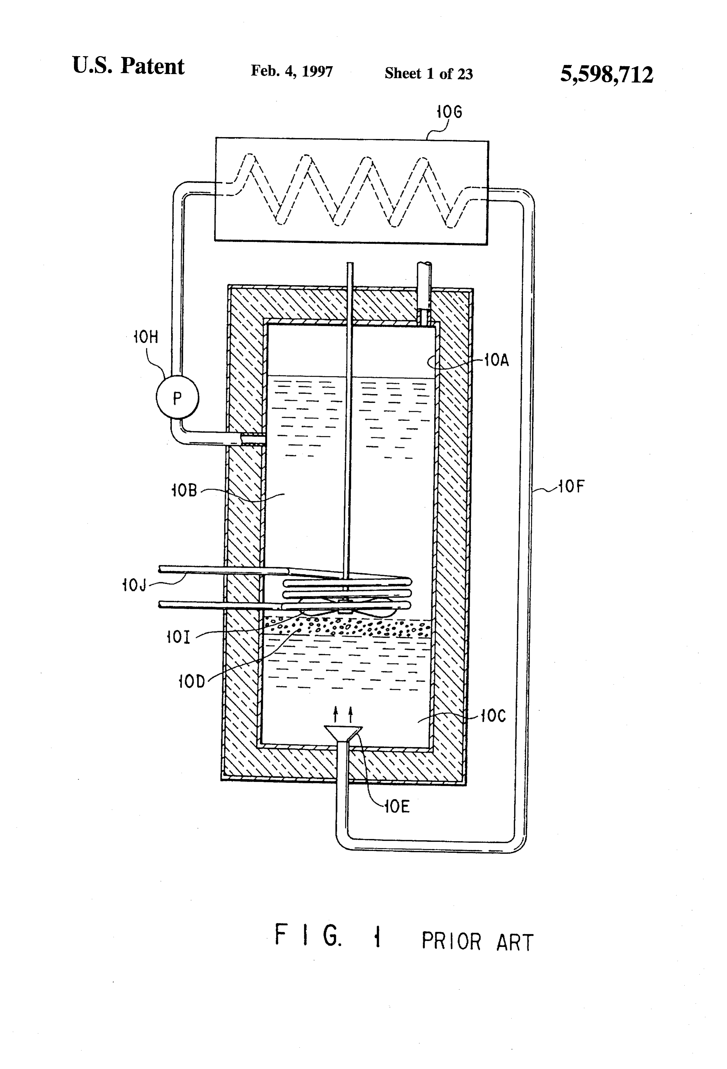
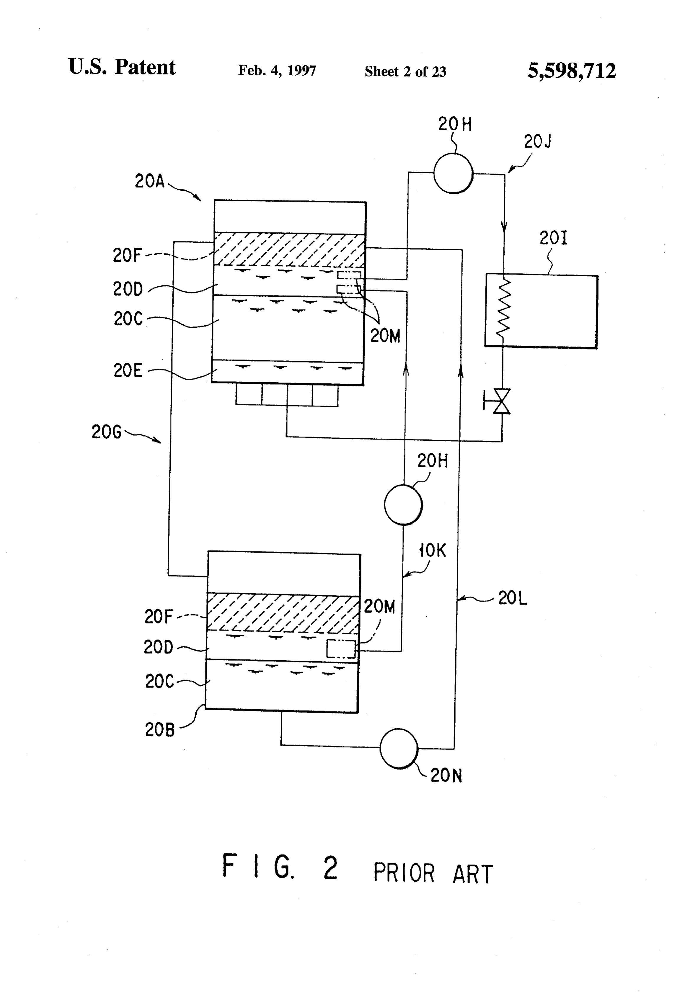
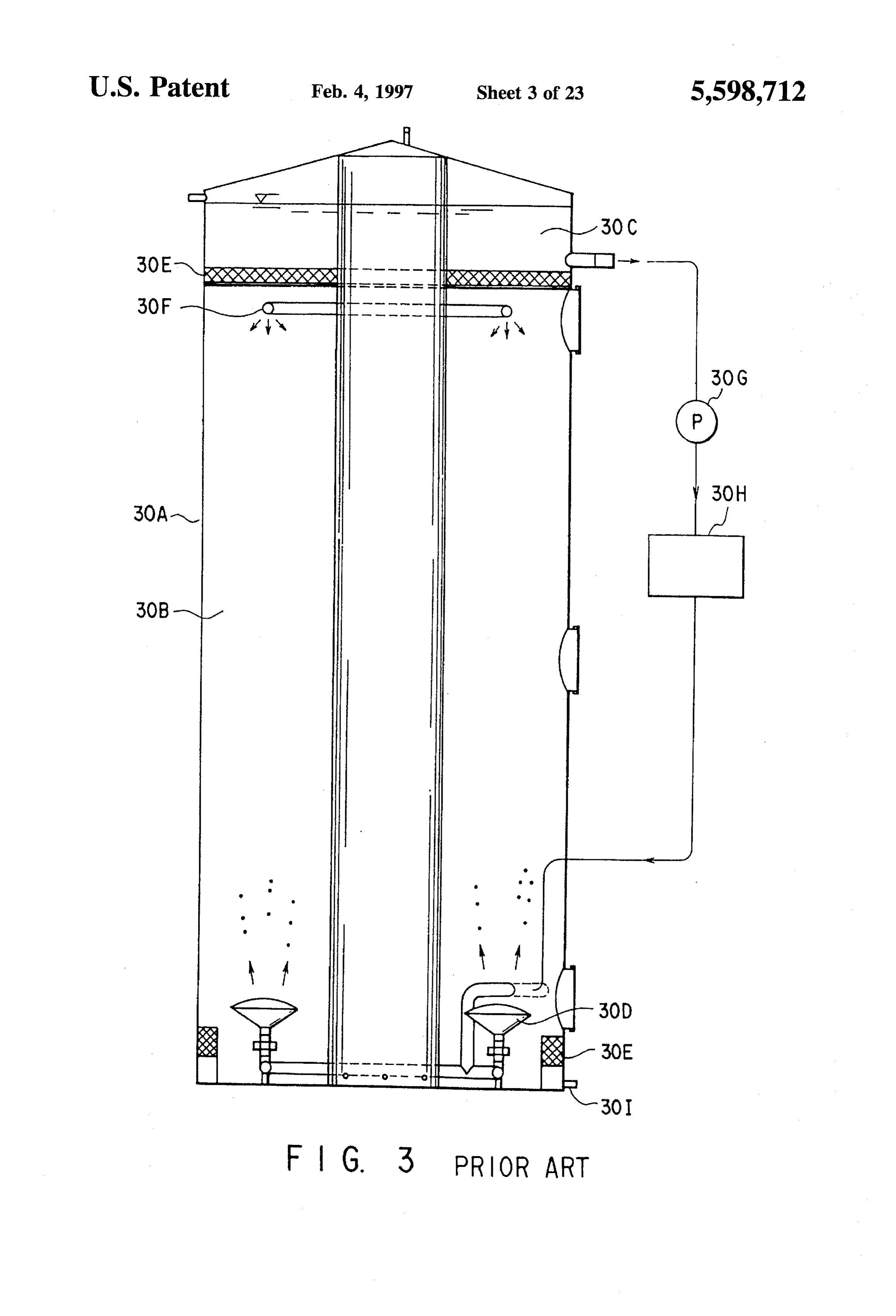
particles can be obtained. The fine ice particles move The outlet port is disposed below the separation film. In upward by the buoyancy thereof. Thus, the non-freezing the bottom portion of the water tank, the cold water outlet liquid is always set in contact with water of 0°C. and the ice port is disposed. With this arrangement, the first liquid making operation is repeated. Therefore, the ice making 55 which is warmed by absorbing heat from the cooling load efficiency is high. can be circulated. Further, it is possible to draw out water As a conventional latent heat accumulation system in directly from the water tank. - which sherbet-state ice is made by direct contact, a latent However, with the above structure, a problem that emul heat accumulation system shown in FIG. 1 cited from U.S. sion of the second liquid occurs in the process of injecting Pat. No. 2,996,894 or a latent heat accumulation system into the water and a problem that the second liquid flows into shown in FIG. 2 cited from Japanese Patent Disclosure No. the air-conditioning load may occur. That is, separation of 2-97845 are provided, for example. the first liquid from the second liquid is imperfect. The latent heat accumulation system shown in FIG. 1 In general, when an oily liquid is used as the second includes a container 10A, oil 10B, water 10C and ice 10D liquid, the second liquid injected into the first liquid is set stored in the container 10, nozzle 10E, oil circulating system 65 into the emulsion state or turbid state. For this reason, it 10F, refrigerator 10G, pump 10H, stirrer 10I, cold carry sometimes takes a long time for the second liquid to be away portion 10J and the like. separated from the first liquid. Therefore, it may become
Page 26
necessary to draw out the second liquid by use of a heat efficient transfer mechanism wherein a solid phase material exchanger, making it necessary to use a large-scale device. which can be used as cooling medium can be smoothly fed For the above-described reason, the above system cannot to a pipe and transferred by a pump. be conveniently used and is not generally accepted by the The above object can be achieved by a latent heat accu users although the ice making efficiency thereof is high. mulation system having a transfer mechanism, the system In a heat accumulation system shown in FIG. 4 cited from comprising:
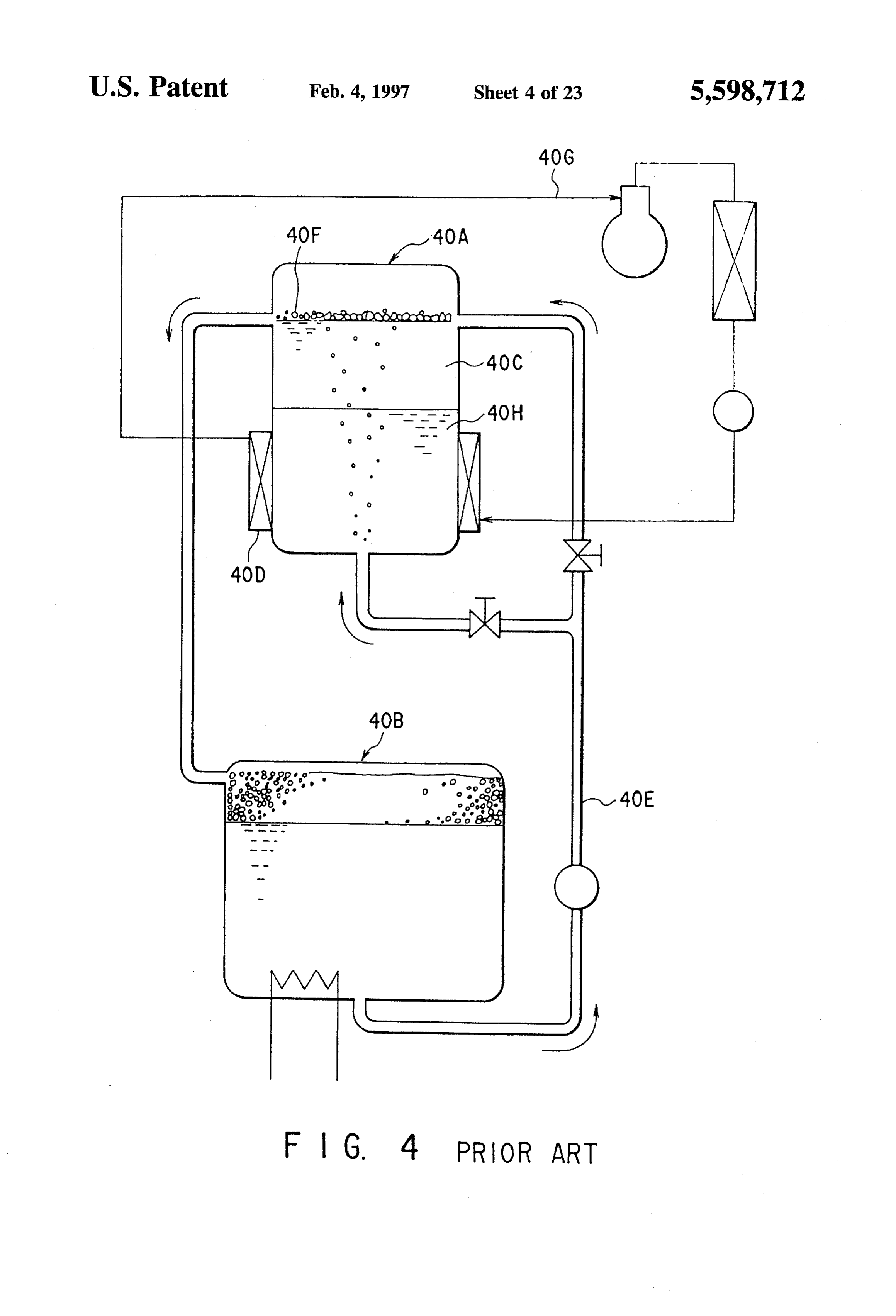
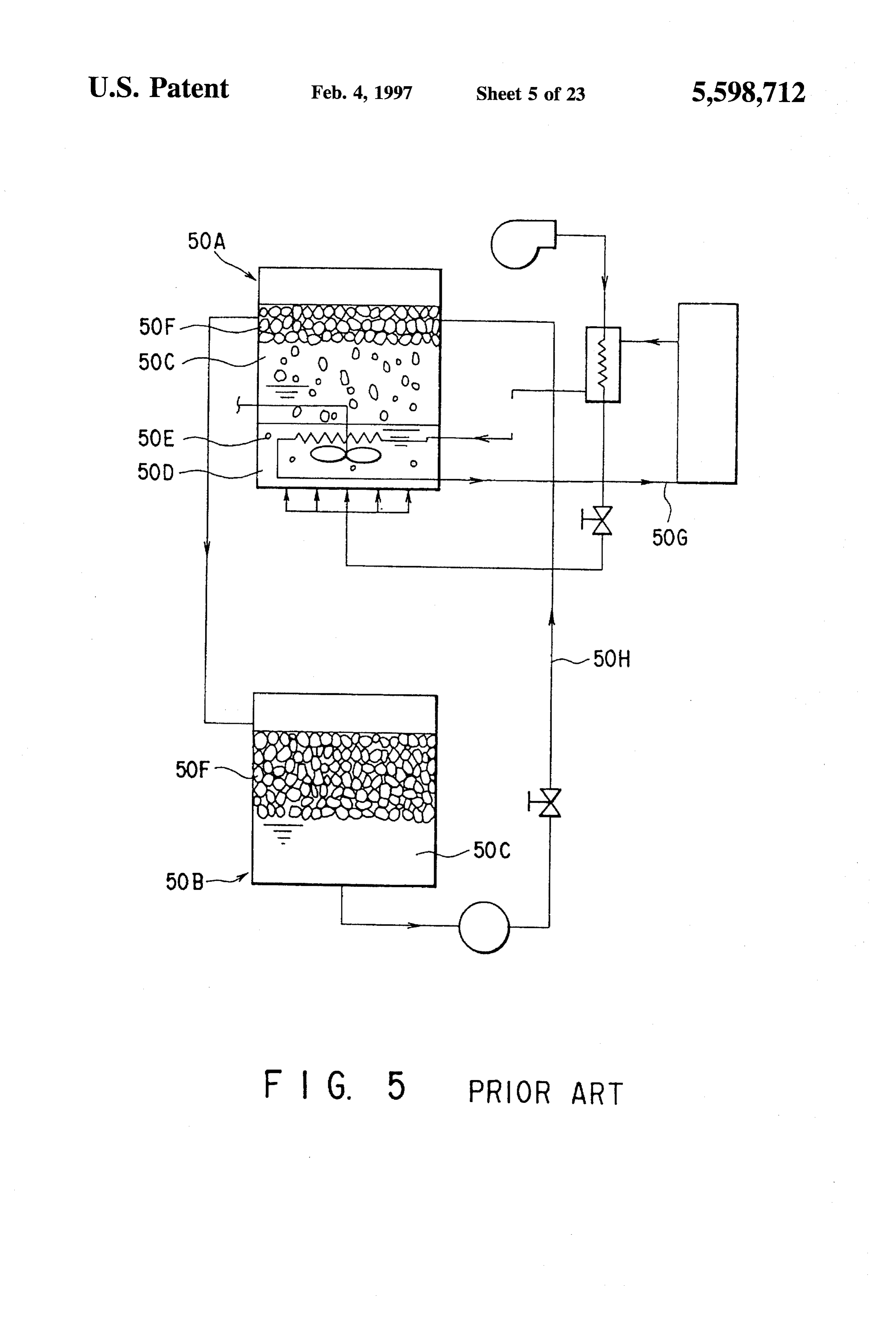
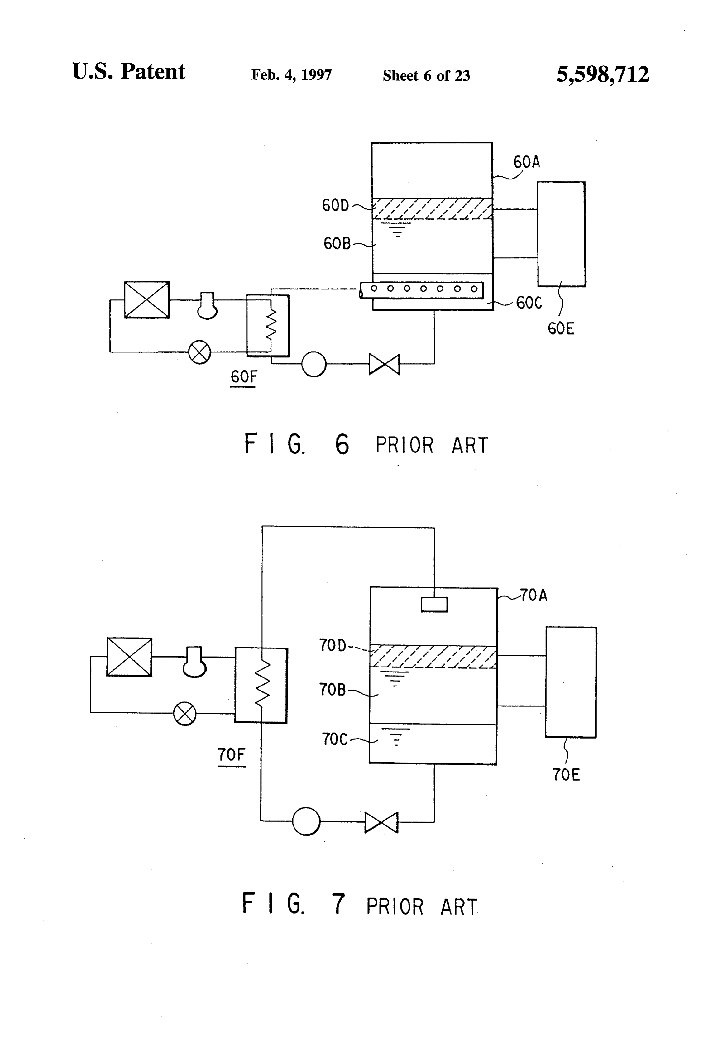
Japanese Patent Disclosure No. 1-244225, a heat accumu a production tank in which a first fluid is put in direct lation system shown in FIG. 5 cited from Japanese Patent contact with a second fluid, which does not combine Disclosure No. 2-110231 and a heat accumulation system with the first fluid, has a specific gravity greater than shown in FIG. 6 cited from Japanese Patent Disclosure No. 10 that of the first fluid and is cooled to a preset tempera 3-140767, a liquid having a specific gravity larger than that ture level, thus producing a solid phase material of the of the first liquid is used as the second liquid. first fluid,
The heat accumulation system shown in FIG. 4 includes a recovery section, formed at a lower part of said pro an ice making tank 40A, heat accumulation tank 40B, water duction tank, for recovering the second fluid descend 40C, heat exchanger 40D, water supply pipe 40E, ice 40F, 15 ing within the production tank; circulating system 40G, ice making liquid 40H and the like. an upward pipe, connected to said production tank, for The heat accumulation system shown in FIG. 5 includes guiding upward a two-phase stream of said first fluid an ice making tank 50A, heat accumulation tank 50B, water and said solid phase material within the production 50C, oil 50D, air 50E, ice 50F, circulating system 50G, tank;
return path 50H, communicating pipe 50I and the like. 20 a transfer pipe, connected to said upward pipe, for trans The heat accumulation system shown in FIG. 6 includes ferring said two-phase stream to a specified place; a water tank 60A, water 60B, oil 60C, ice 60D, cold a reservoir tank for storing the two-phase stream trans transferring section 60E, cooling system 60F and the like. ferred via said transfer pipe; In the heat accumulation systems shown in FIGS. 4 to 6, 25 a first fluid circulation system for draining the first fluid the second liquid is stored in the bottom portion of the water from the reservoir tank and introducing the drained first tank. The second liquid is cooled by a heat exchanger or fluid into the production tank; and refrigerator. Water or the first liquid is injected into the a second fluid circulation system for cooling the second second liquid which is cooled from the bottom portion of the fluid recovered by said recovery section and feeding the water tank (FIGS. 4 and 6). The boundary portion between 30 cooled second fluid into the production tank for bring the first and second liquids is stirred to change ice formed in ing the second fluid into direct contact with the first the boundary portion into fine ice particles (FIG. 5). In this fluid.
system, the temperature of the second liquid introduced into Additional objects and advantages of the invention will be the refrigerator becomes relatively lower than that of the set forth in the description which follows, and in part will be freezing or solidifying point (0°C. in the case of water) of 35 obvious from the description, or may be learned by practice the first liquid. Further, in the above systems, a problem that of the invention.
the freezing efficiency cannot be enhanced although a high may be realizedThe and objects and advantages of the invention obtained by means of the instrumen heat transfer characteristic can be attained by the direct talities and combinations particularly pointed out in the contact between the first and second liquids occurs. appended claims.
In order to solve the above problem, a latent heat accu 40 mulation system shown in FIG.7 cited from Japanese Patent BRIEF DESCRIPTION OF THE DRAWINGS Disclosure No. 3-140767 is proposed. The latent heat accu The accompanying drawings, which are incorporated in mulation system shown in FIG.7 includes a water tank 70A, and constitute a part of the specification, illustrate presently water 70B, oil 70C, ice 70D, cold transferring section 70E, preferred embodiments of the invention, and together with cooling system 70F and the like. 45 the general description given above and the detailed descrip In the latent heat accumulation system shown in FIG. 7, tion of the preferred embodiments given below, serve to the second liquid is collected from the bottom portion of the explain the principles of the invention. water tank. The second liquid is cooled to a temperature FIG. 1 is a view showing the first construction of a equal to or lower than the freezing or solidifying point of the conventional first liquid (water) by the refrigerator. The cooled second 50 system using direct a contact type latent heat accumulation non-freezing liquid which is not soluble in liquid is poured from a portion in the air into the water tank. Water,
In this case, while the second liquid (oily liquid) which is heavier than water is falling and deposited in the water, it conventionalFIG. 2 is a view showing the second construction of the sufficiently exchanges heat with the water. The temperature system; direct contact type latent heat accumulation of the second liquid is raised to substantially the water 55 temperature by the time the second liquid is collected from FIG. 3 is a view showing the third construction of the the bottom portion of the water tank. Therefore, the freezing conventional system;
direct contact type latent heat accumulation efficiency of the second liquid can be held high.
However, in this system, hard and heavy ice blocks are FIG. 4 is a view showing the fourth construction of the formed. Generally, such ice blocks are deposited in the 60 conventional direct contact type latent heat accumulation boundary portion between the first and second liquids and system;
cannot rise to the surface. The same problem occurs in the FIG. 5 is a view showing the fifth construction of the systems of FIGS. 4, 5 and 6. conventional direct contact type latent heat accumulation
SUMMARY OF THE INVENTION
system;
65 FIG. 6 is a view showing the sixth construction of the
The object of the present invention is to provide a latent conventional direct contact type latent heat accumulation heat accumulation system having a highly reliable, highly System;
Page 27
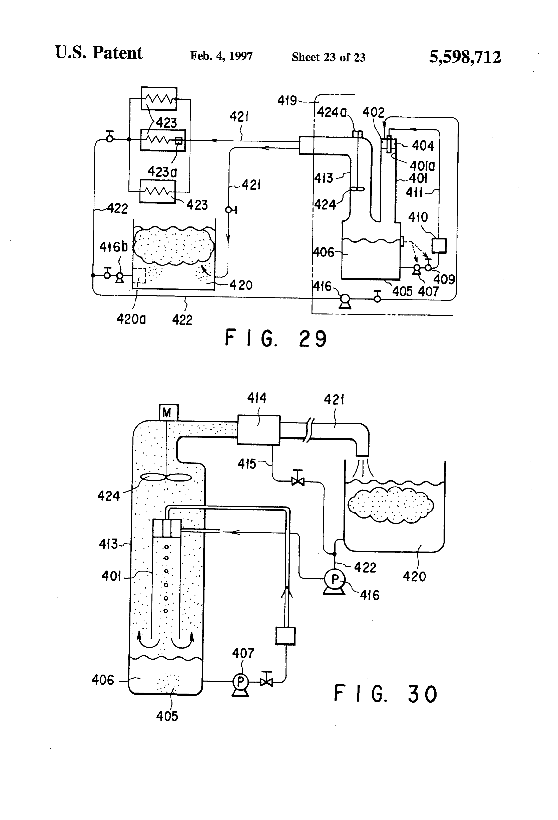
FIG. 7 is a view showing the seventh construction of the FIG. 30 shows a fifth embodiment of a latent heat conventional direct contact type latent heat accumulation accumulation system having an ice transferring mechanism system; according to the invention.
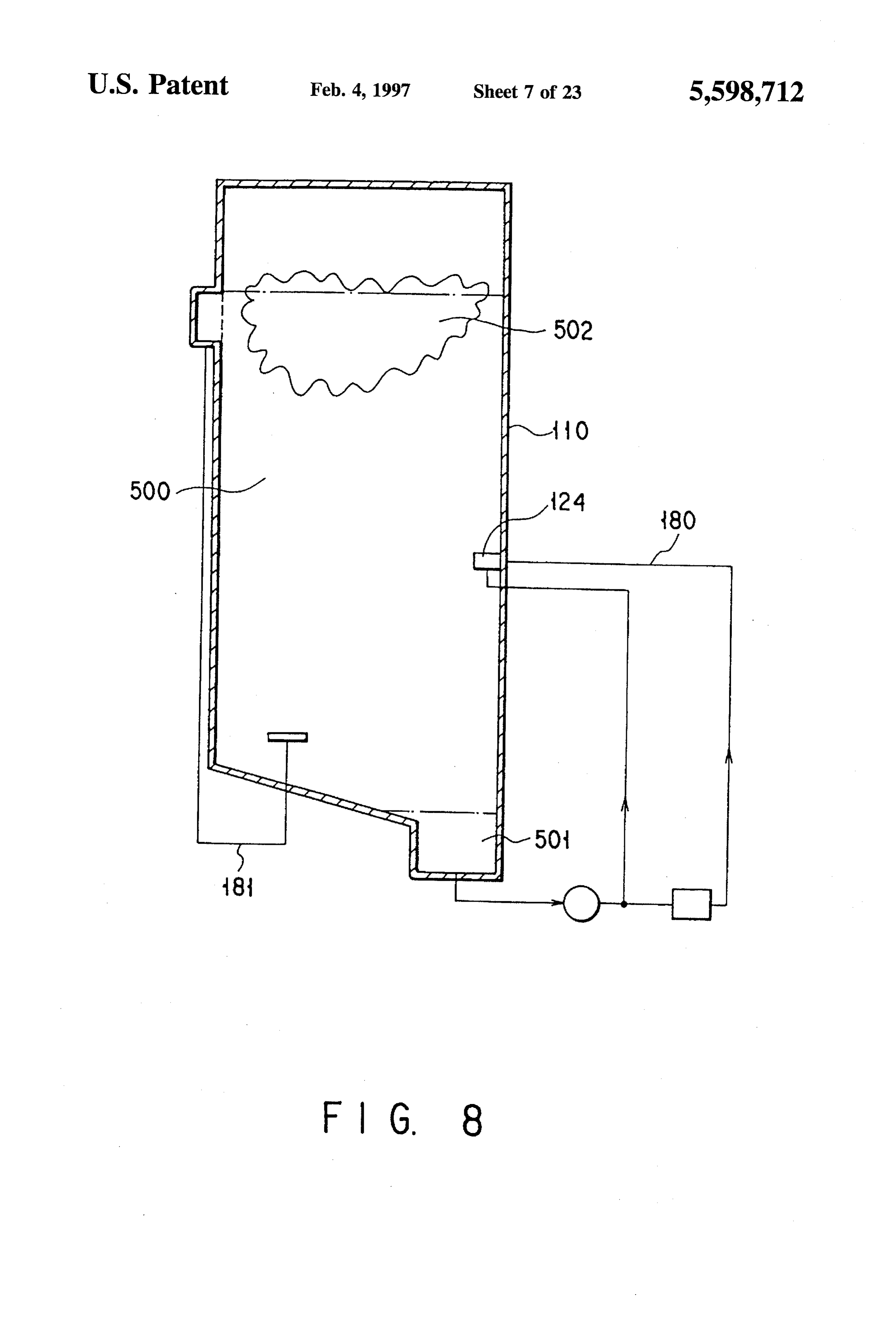
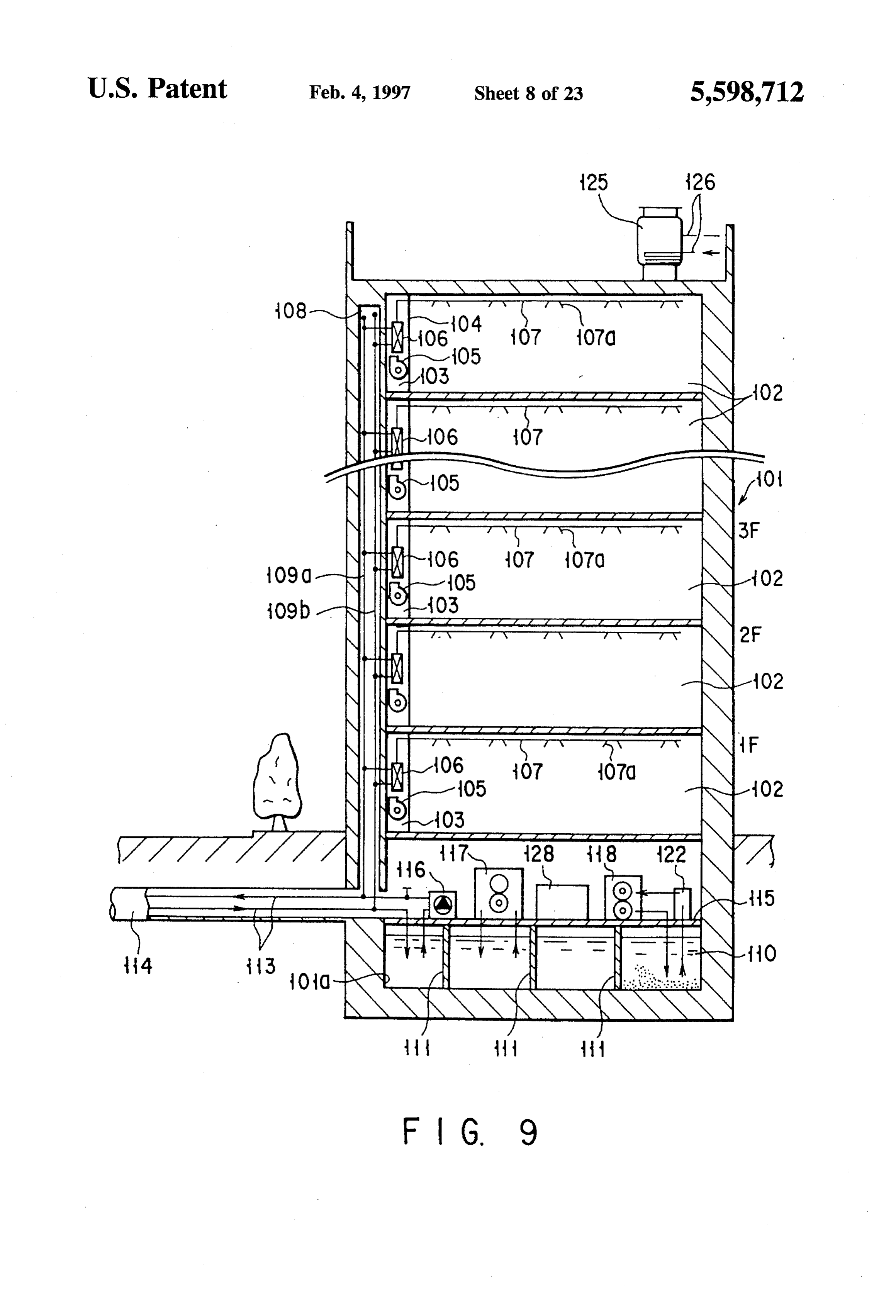
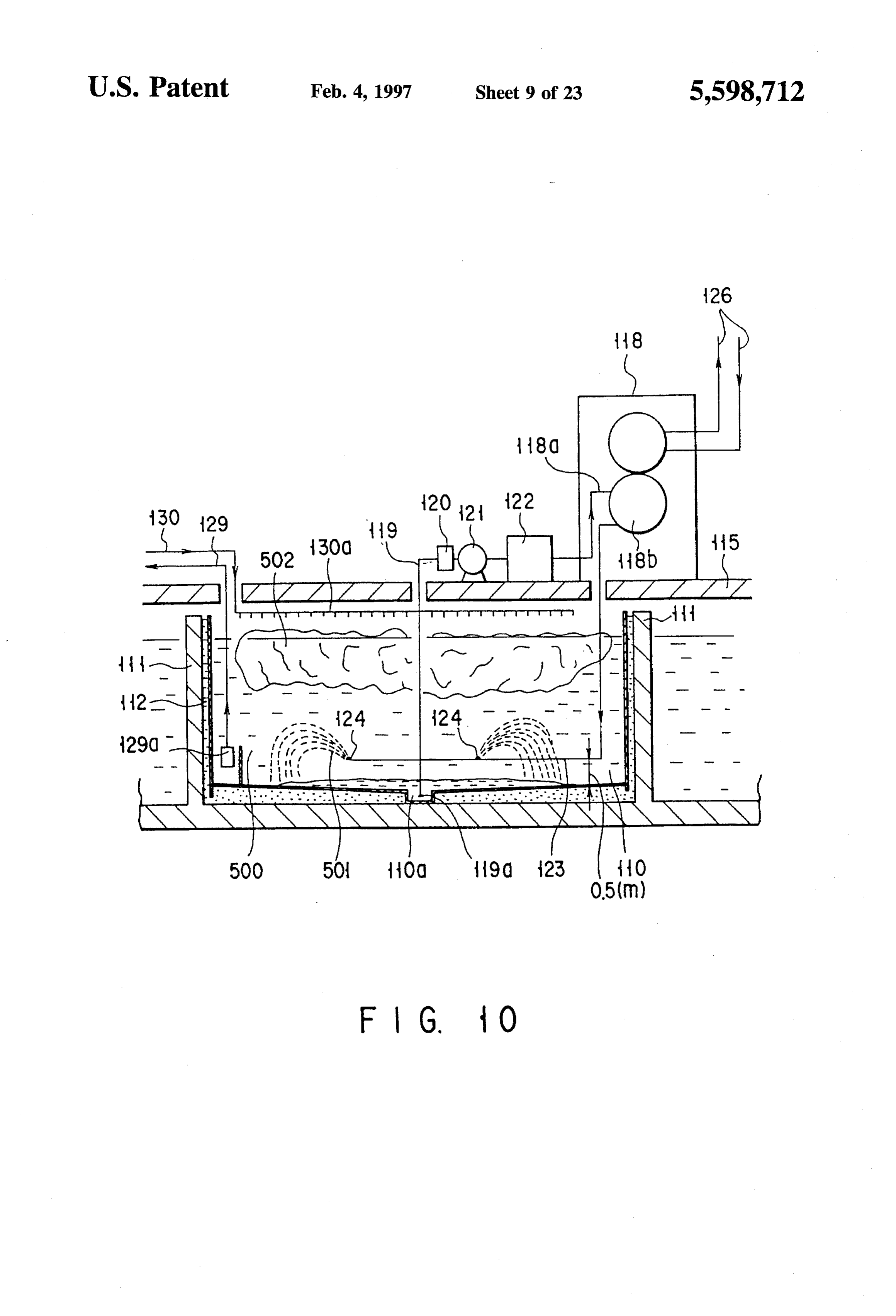
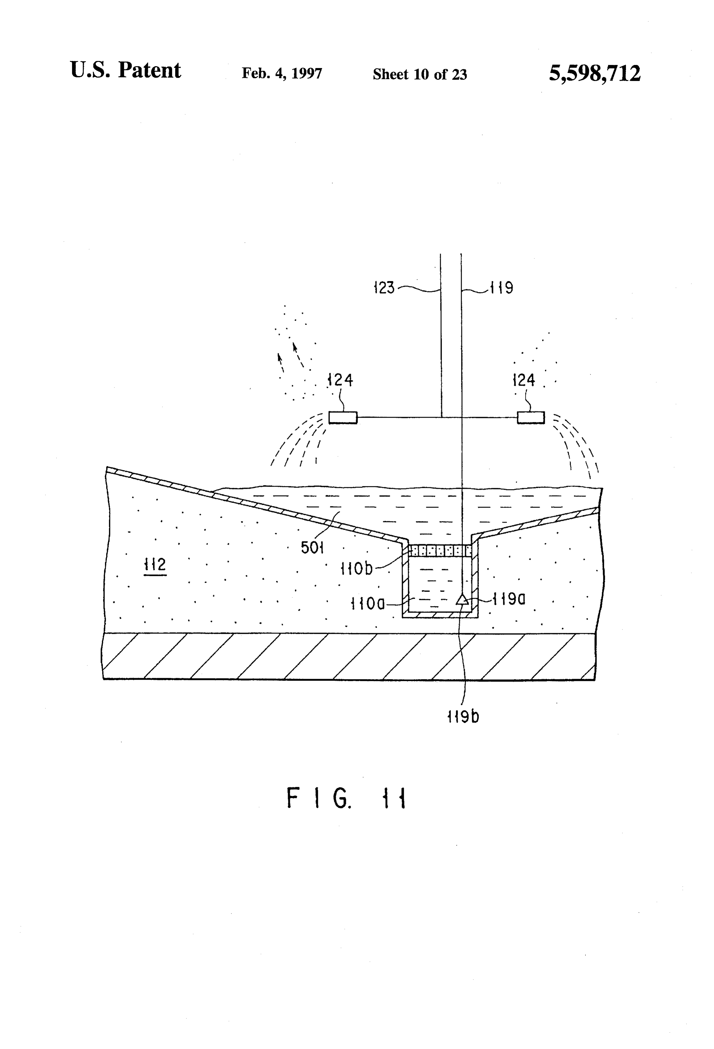
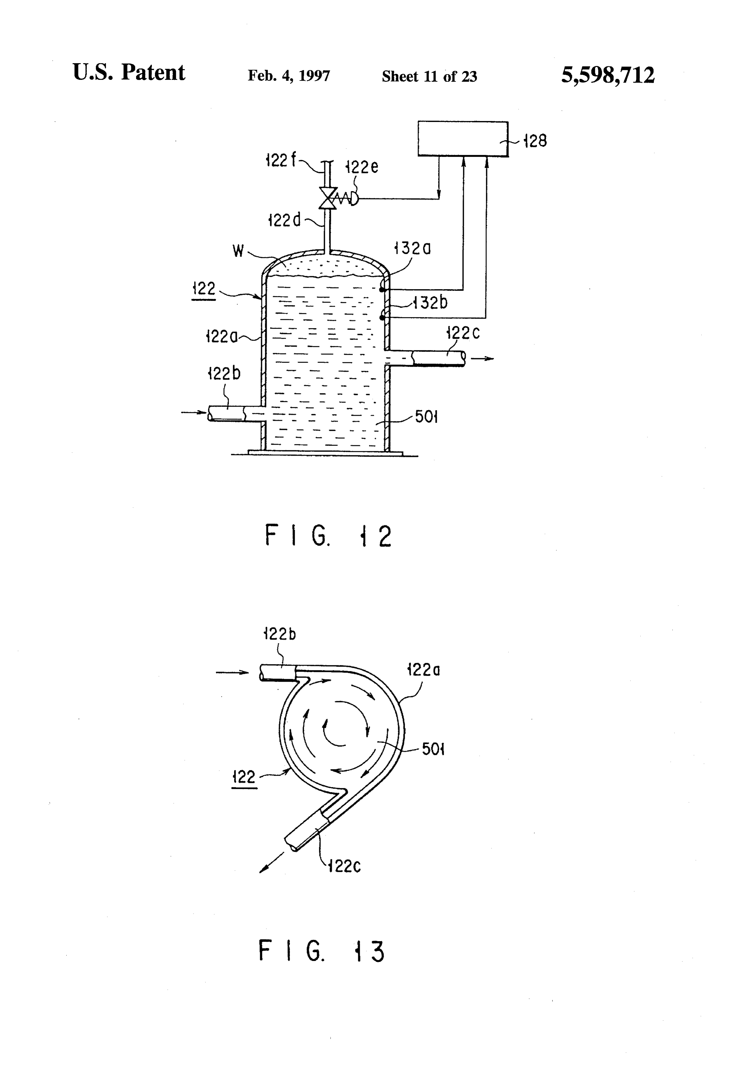
FIG. 8 is a view for illustrating the principle of this invention; DETALED DESCRIPTION OF THE FIG. 9 is a cross sectional view of a latent heat accumu PREFERRED EMBODIMENTS lation system according to a first embodiment of this inven FIG. 8 is a view for illustrating the principle of a latent tion in a case where it is disposed in a regional heat supply heat accumulation system according to this invention. The plant installed in the basement of a multistoried building; latent heat accumulation system includes a water tank 110 in FIG. 10 is a cross sectional view showing the main 10 which water 500, refrigerant (trade name: Fluorinate) 501 portion of the latent heat accumulation system of the same and ice 502 are stored. A refrigerant circulating system 180 embodiment; and a water circulating system 181 are additionally provided FIG. 11 is an enlarged cross sectional view of a water tank for the water tank 110. The construction of FIG. 8 is used in shown in FIG. 10; the systems shown in FIGS. 8 to 26. FIG. 12 is an enlarged cross sectional view of a refrigerant 15 FIGS. 9 and 10 are views showing one embodiment of a separation and collection device utilizing the centrifugal latent heat accumulation system according to this invention. force shown in FIG. 10; As shown in FIG. 9, storage chambers 103 are defined by FIG. 13 is a partial cross sectional view of the refrigerant partition boards 104 in respective rooms 102 on the respec separation and collection device of FIG. 12 as viewed from 20 tive stories of a multistoried building 101. Indoor heat the above; exchangers 106 having cooling fans 105 are disposed in the FIG. 14 is a cross sectional view of the main portion of a pipesrespective storage chambers 103. Further, cold wind supply latent heat accumulation system according to a second the respective 107 having air blow-off ports 107a are connected to embodiment of this invention in a case where it is disposed indoor heat exchangers 106. The cold wind on the rooftop of building; 25 supply pipes 107 are arranged to extend along the ceiling sides of the respective
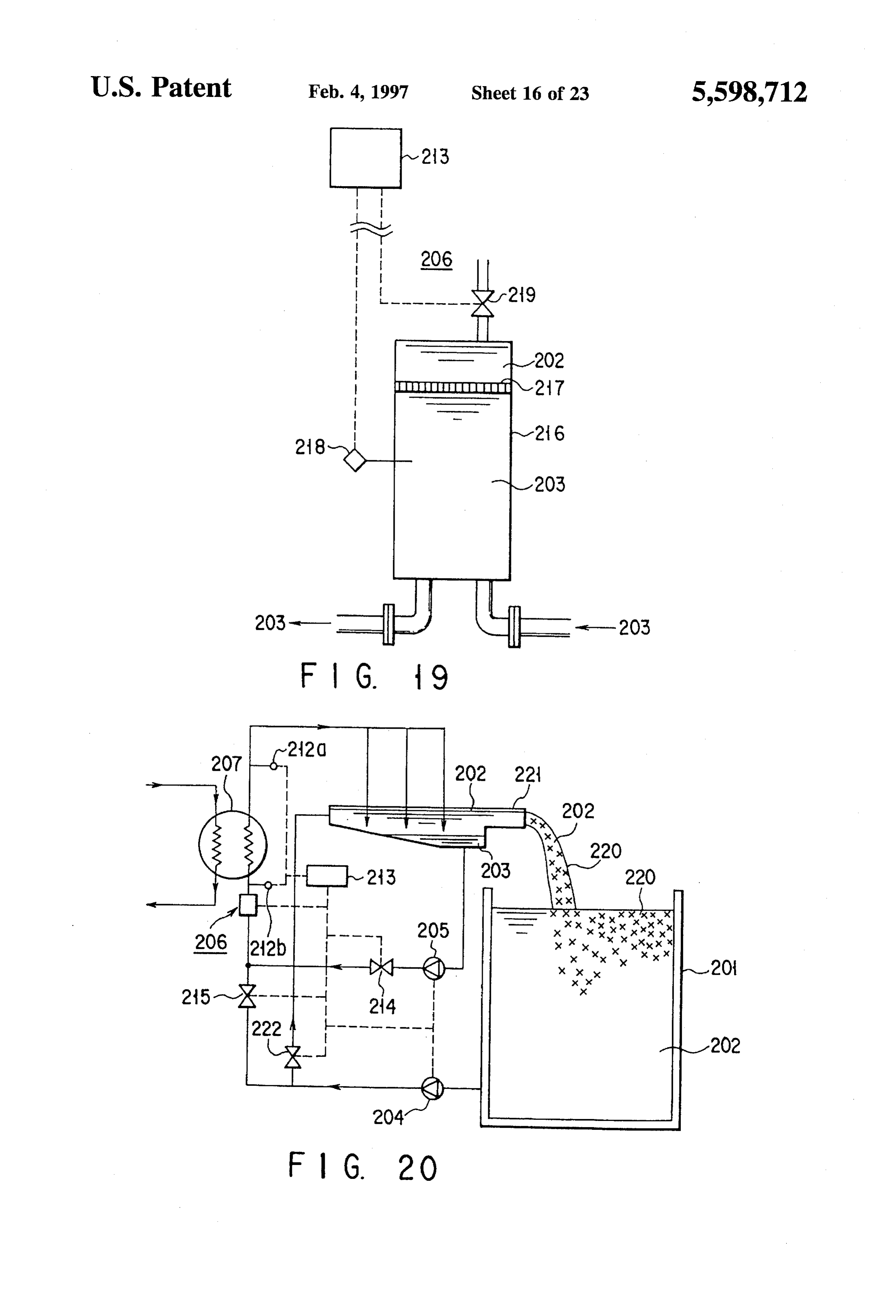
FIG. 15 is a cross sectional view showing a first example formed in a vertical direction rooms 102. A through air hole is of the construction of an outlet nozzle portion for refrigerant storied building 101 which liesinnear that portion of the multi the storage chambers used in the latent heat accumulation system of the same 103. A cold water supply pipe 109a and returnpipe 109b are embodiment, laid in the through air hole 108. The supply pipe 109a and FIG. 16 is a cross sectional view showing a second 30 return pipe 109b are connected to all of the indoor heat example of the construction of the outlet nozzle portion for exchangers 106. Each of the indoor heat exchangers 106 refrigerant, creates cold air by the heat exchange between the cold water FIG. 17 is a cross sectional view showing a third example and air by means of the cooling fan 105. The cold air is of the construction of the outlet nozzle portion for refriger 35 supplied into the room 102 via the cold wind supply pipe ant, 107 to lower the room temperature to a preset level. The cold FIG. 18 is a view showing the construction of one water subjected to the heat exchange is returned to the water embodiment of this invention; tank 110 installed in the basement 10a of the multistoried FIG. 19 is a view showing the construction of a separator building 101 as will be described later via the return pipe
used in the embodiment of this invention; 40
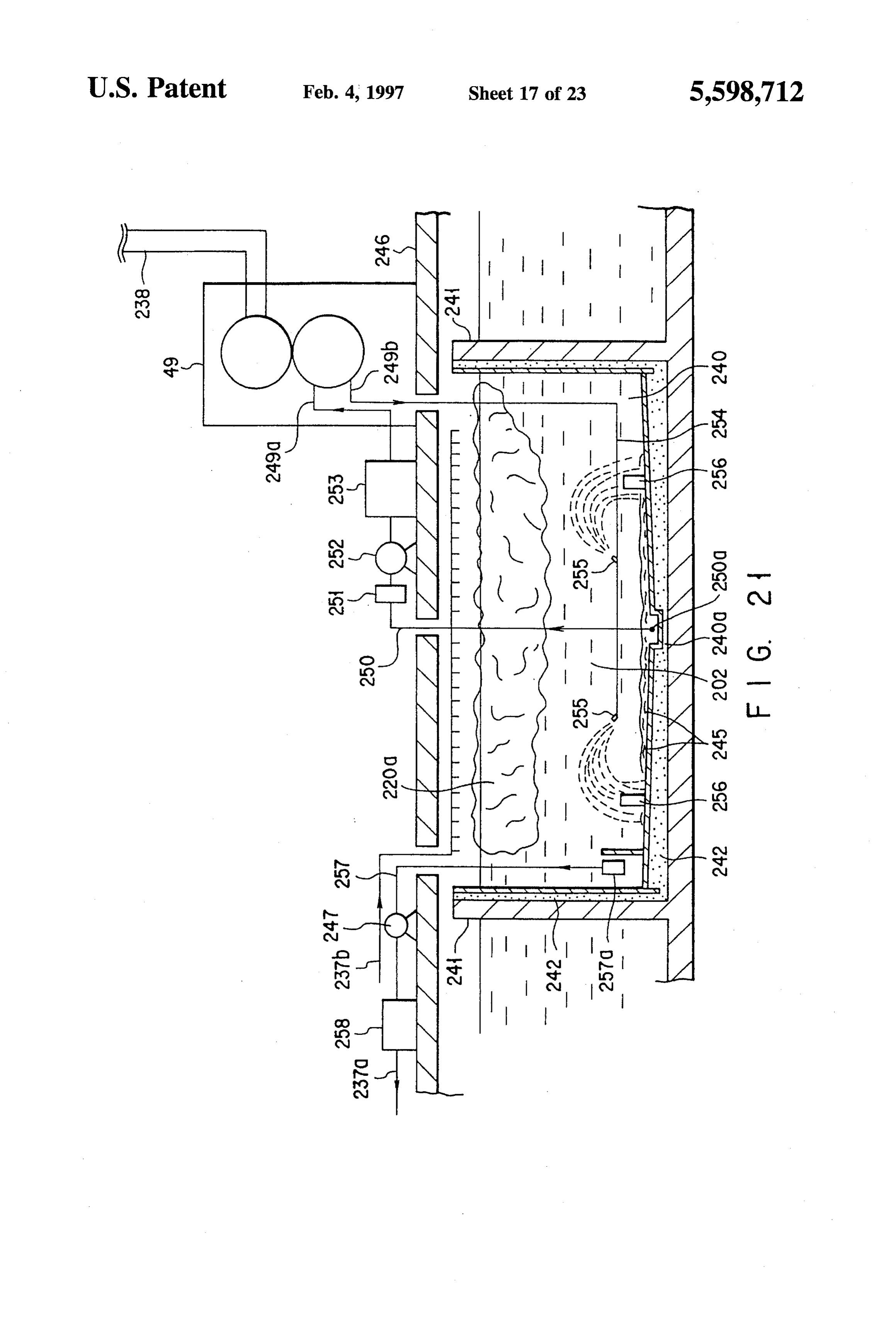
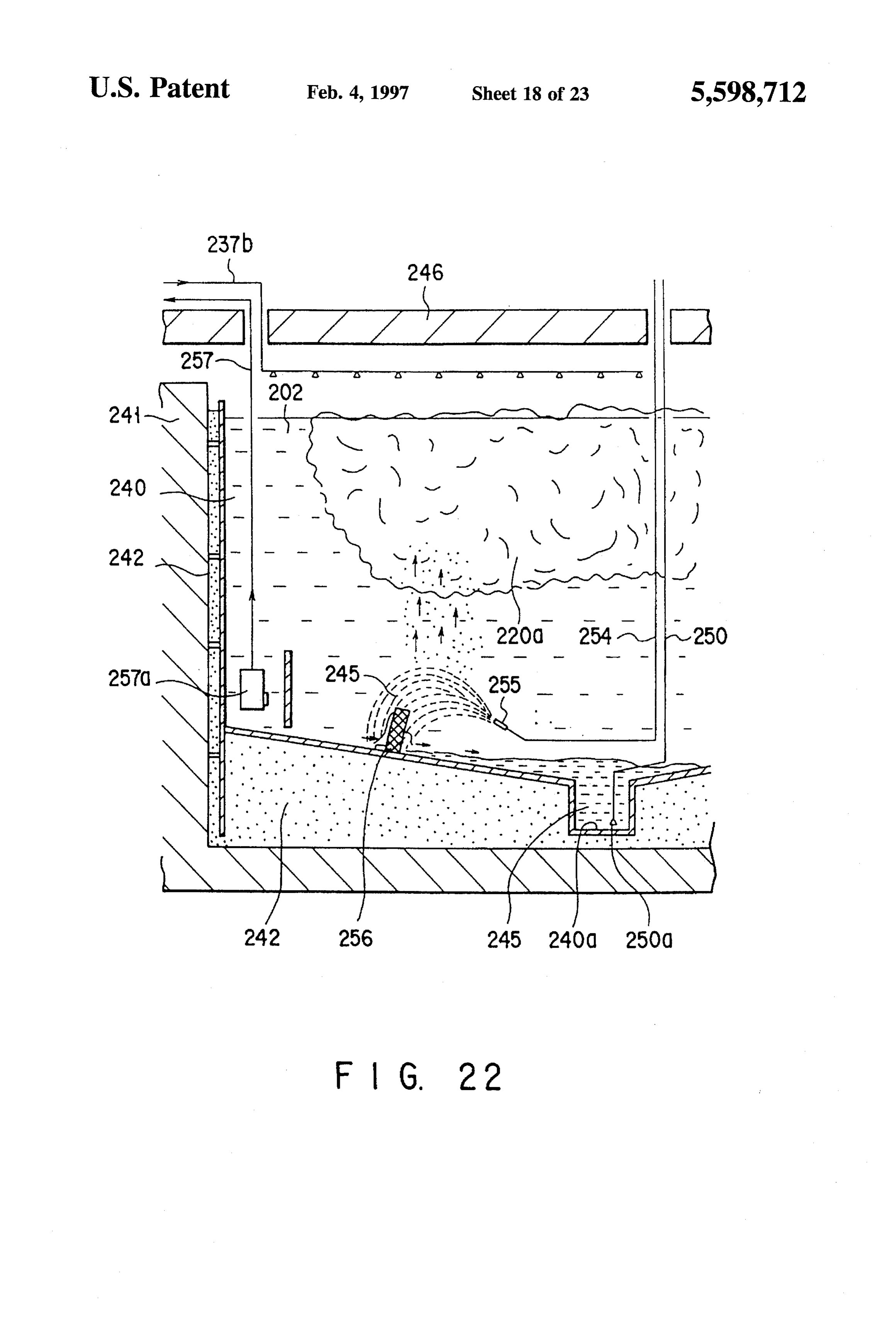
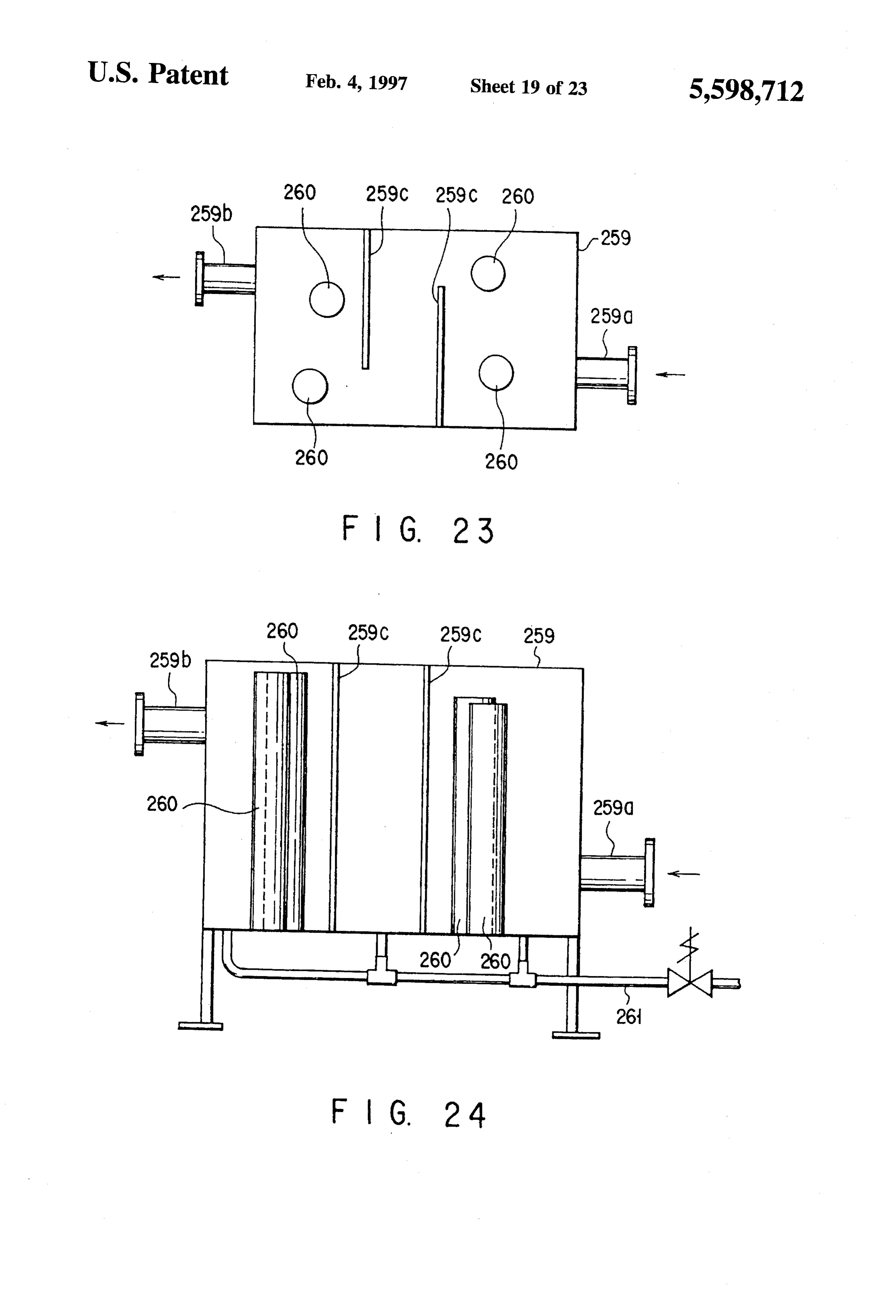
FIG. 20 is a view showing the construction of another As shown in FIG. 10, the basement 10a of the multi embodiment of this invention; storied building 101 is divided by partition boards 111 each FIG. 21 is a view showing the construction of still another having a communication hole. Thus, the water tank 110 has a plurality of water tank units. The bottom portion of the embodiment of this invention applied to an air-conditioner 45 water tank 110 is formed to have inclined surfaces which shown in FIG. 9; extend downwardly from the peripheral portions towards the FIG. 22 is an enlarged view of the main portion of the center and a concave portion is formed as a storage portion embodiment shown in FIG. 21; 110a for a second liquid 501 in the central bottom portion. FIG. 23 is a plan view showing the construction of a Heat insulation sheets 112 are attached to the bottom and separation tank used in the embodiment shown in FIG. 21; 50 inner wall portions of the water tank 110 and the partition FIG.24 is across sectional view of the tank shown in FIG. boards 111.
23; As shown in FIG. 9, the water tank 110 is connected to a FIG. 25 shows a first embodiment of a latent heat accu - commercial water pipe 113 via a closing valve. The com mulation system having an ice transferring mechanism mercial water pipe 113 is disposed in the underground according to the present invention; 55 multi-purpose duct buried in the ground outside the building FIG. 26 is a cross sectional view of the system shown in 101.
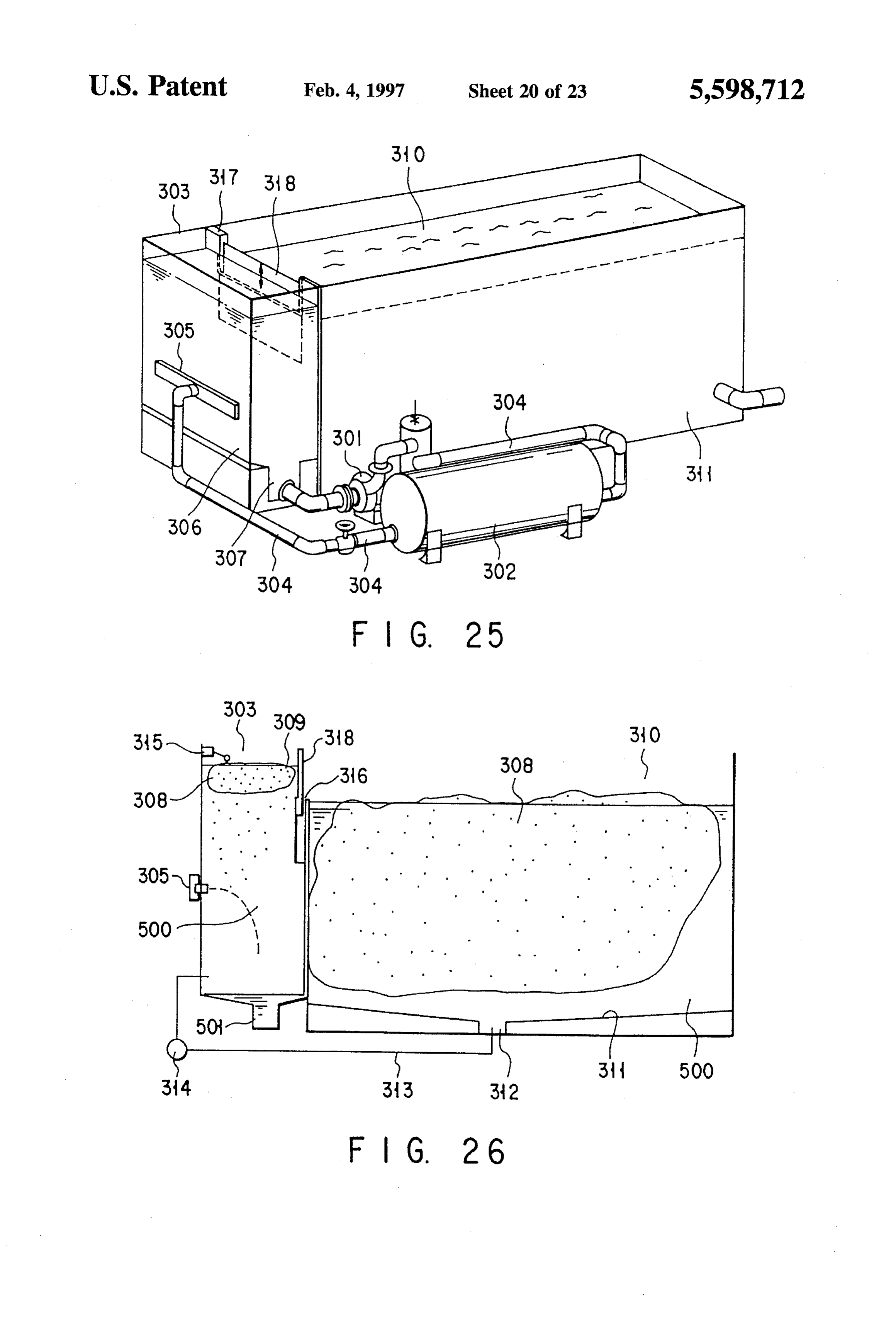
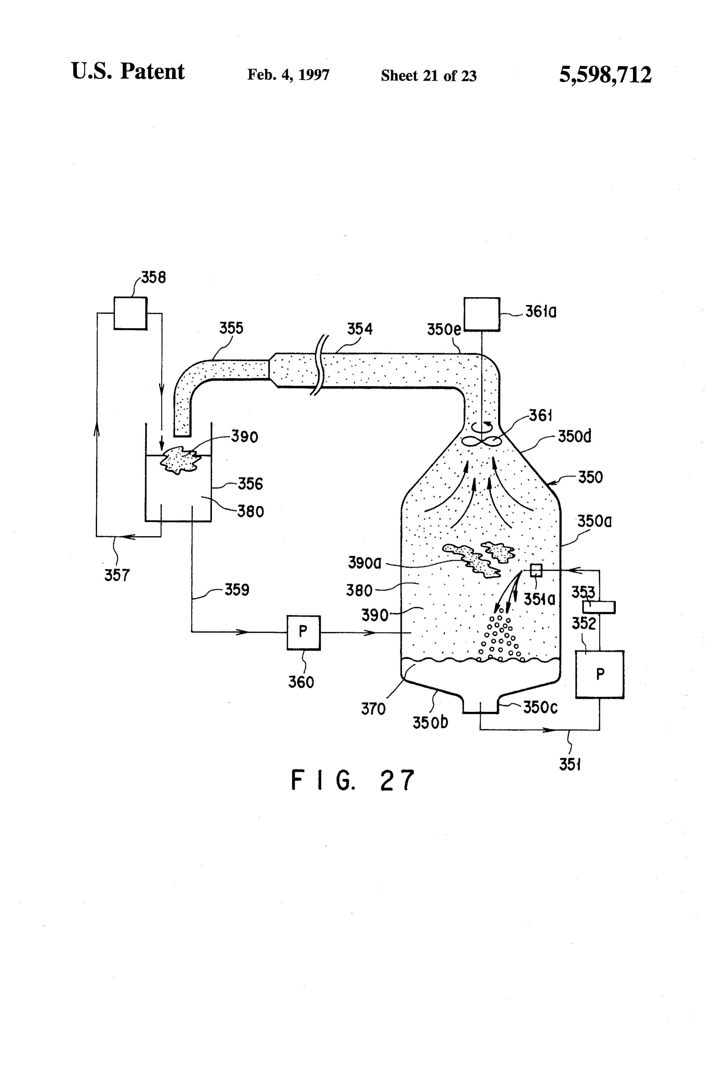
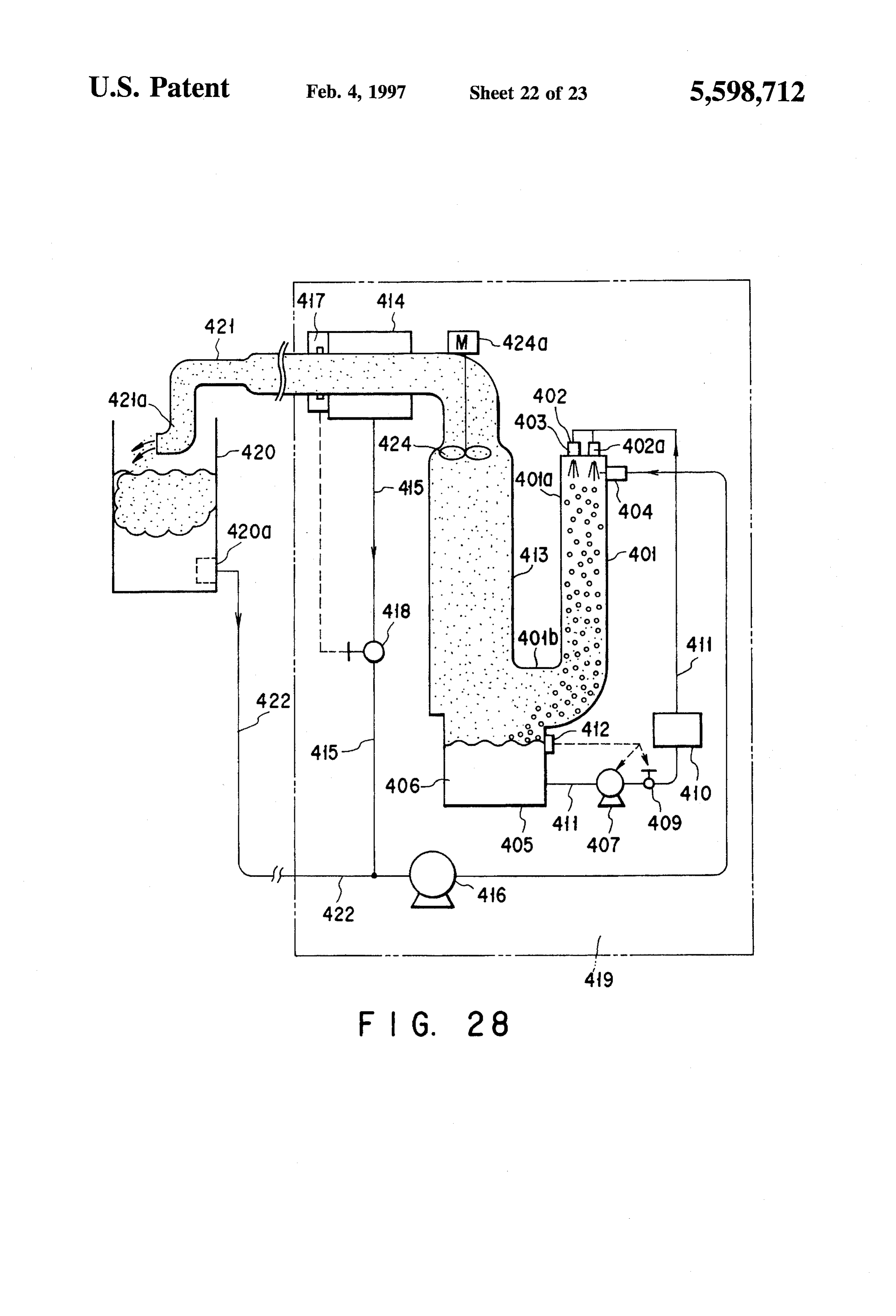
FIG. 25; Cold water 500 or the first liquid and a refrigerant 501 or FIG. 27 shows a second embodiment of a latent heat the second liquid having a larger specific gravity are mixed and stored in the water tank 110. In this embodiment, as the accumulation system having an ice transferring mechanism refrigerant according to the invention; 501, a refrigerant having a specific gravity which FIG. 28 shows a third embodiment of a latent heat is more than 1.5 times that of the first liquid and a solidifying point lower accumulation system having an ice transferring mechanism shown in FIGS. than the first liquid is used, for example. As according to the invention; 10 and 11, when the refrigerant 501 is deposited on the bottom portion of the water tank 110, it
FIG. 29 shows a fourth embodiment of a latent heat 65 flows towards the storage portion 110a along the inclined accumulation system having an ice transferring mechanism surface of the bottom portion of the water tank 110 by its according to the invention; and own weight and remains there. -
Page 28
A base plate 115 is horizontally disposed on the upper 122f for draining cold water via an electromagnetic valve portion of the basement 101a of the multistoried building 122e. A pair of electrical resistance sensors 132a and 132b 101 to cover the water tank 110. A pump 116 and heat pump are disposed on the inner wall of the tank 122a in position 117 constructing a cold/warm water supplying system are higher than the inlet port 122b and placed apart from each disposed on the base plate 115. The pump 116 and heat pump other in the vertical direction. The electrical resistance 117 are connected to the supply pipes 109a and 109b via a sensors 132a and 132b are used to detect the boundary switching valve. between the cold water 500 and the refrigerant 501 by Further, a refrigerating machine 118 is disposed on the utilizing the difference between the electrical resistances base plate 115. The inlet port 118a of the refrigerating thereof. Detection signals from the electrical resistance machine 118 is connected to a supply pipe 119. The supply 10 sensors 132a and 132b are supplied to the air-conditioning pipe 119 has an inlet port 119a for refrigerant. The inlet port control device 128 via respective lines. 119a is formed in communication with the storage portion The air-conditioning control device 128 controls the open/ 110a formed in the bottom portion of the water tank 110. As closing position of the electromagnetic valve 122e according shown in FIG. 11, a vortex preventing portion 110b formed to the detection signals of the electrical resistance sensors of a porous plate is disposed over the storage portion 110a. 15 132a and 132b to control the displacement of cold water so The vortex preventing portion 110b is provided to prevent a as to separate the refrigerant 501 and the cold water 500 in vortex from being generated by the refrigerant 501 flowing the tank 122a from each other at the reference boundary into the storage portion 110a. Further, a guide 119b for surface. When the water is accumulated separately from the defining the intake direction is disposed on the inlet port refrigerant in the tank 122a of the water/liquid separation 119a provided at the end portion of the supply pipe 119 so 20 device 122, the position of the boundary surface between the as to prevent the cold water 500 from being mixed into the water and refrigerant can be detected by the electrical refrigerant 501. resistance sensors 132a and 132b. The detection signals of The supply pipe 119 is connected to the inlet port 118a of the electrical resistance sensors 132a and 132b are supplied the refrigerating machine 118. A strainer 120, suction pump to the air-conditioning control device 128 which opens the 121 and water/liquid separation device 122 are connected to 25 electromagnetic valve 122e according to the detection sig the supply pipe 119 in this order. nals. Therefore, the water in the tank 122a is forcedly moved The refrigerating machine 118 has an evaporator 118b. A upwardly by the pressure of the refrigerant newly drawn into delivery pipe 123 is connected to the evaporator 118b. The the tank 122a and is drained via the drain pipe 122f. As a delivery pipe 123 is laid in the cold water 500 in the water result, the boundary surface between the cold water and tank 110. The end portion of the delivery pipe 123 is held in 30 refrigerant rises, and when the reference boundary surface is a horizontal position near the bottom surface of the water detected by the electrical resistance sensors 132a and 132b, tank 110. A plurality of injection nozzles 124 are formed on the detection signals of the electrical resistance sensors 132a the end portion of the delivery pipe 123. and 132b are supplied to the air-conditioning control device Further, as shown in FIG. 9, an air-conditioning control 128 which in turn closes the electromagnetic valve 122e in device 128 is disposed on the base plate 115 near the 35 response to the detection signals. Thus, the water level is refrigerating machine 118. The air-conditioning control controlled to be automatically set at the reference boundary Surface.
device 128 controls the air-conditioning operation in the multistoried building 101 and various instruments in the heat Next, the operation of the latent heat accumulation system Supplying plant. according to this embodiment with the above structure is A cold water supply pipe 129 has an intake port 129a for pump 121 isReferring explained.
driven by to FIGS. 9 and 10, when the suction mainly utilizing cheap electric power drawing cold water. The intake port 129a is disposed in the cold water in the water tank 110. The cold water supply pipe liquid which is stored in thethe during the nighttime hours, refrigerant 501 or the second storage portion 110a formed in 129 is connected to the lower end portion of the supply pipe the bottom portion of the water tank 110 109a shown in FIG. 9 via an open/closing valve (not shown). 45 upwardly to the water/liquid separation isdevice forcedly supplied 122 via the
A returning pipe 130 is connected to the lower end portion supply pipe 119. In the water/liquid separation device 122, of the return pipe 109 shown in FIG. 9. The returning pipe cold water 500 or first liquid mixed in the refrigerant 501 130 is connected to a sprinkling pipe 130a disposed in a although small in amount is separated from the refrigerant. space between the water tank 110 and the base plate 115. The As explained with reference to FIGS. 12 and 13, the sepa sprinkling pipe 130a has a plurality of cold water discharg 50 rated cold water 500 is returned to the water tank 110 via the ing ports for returning cold water into the water tank 110. drain pipe 122f and the high purity refrigerant 501 is The refrigerating machine 118 is controlled according to supplied to the refrigerator 118. The refrigerator 118 cools the operation control of the air-conditioning control device the refrigerant 501 fed from the water/liquid separation 128. The control operation of the air-conditioning control device 122 to a temperature lower than the freezing point (0° device 128 is effected so as to supply the refrigerant to a 55 C.) of water (the first liquid). The cooled refrigerant 501 is plurality of water tank units of the water tank 110 simulta fed to the plurality of tank units of the water tank 110 via the neously or with time delay. delivery pipe 123 and injected from the injection nozzles The water/liquid separation device 122 is constructed as 124 into the cold water 500 in the respective tank units shown in FIGS. 12 and 13. That is, the water/liquid sepa simultaneously or with time delay. As a result, the cold water ration device 122 has a tank 122a. The tank 122a has an inlet 60 500 is subjected to the heat exchange with respect to the port 122b and an outlet portion 122c formed in position refrigerant 501 which is injected from the injection nozzles lower than the inlet port 122b. Further, an exhaust port 122d 124 and kept at an extremely low temperature. is formed in the upper surface portion of the tank 122a. The In this case, the injection nozzles 124 are set insufficiently inlet port 122b of the tank 122a is connected to the suction high positions from the bottom surface of the water tank 110 pump 121 via a communicating pipe. The outlet port 122c is 65 so as to permit the refrigerant 501 injected from the nozzles connected to the inlet port 118a of the refrigerator 18. and the cold water 500 to be fully subjected to the heat Further, the exhaust port 122d is connected to a drain pipe eXchange with each other. For example, the injection nozzles
Page 29
124 are set above and apart at least 0.5 m from the boundary the novel plant, the total effect including the effect that the surface between the first and second liquids. With this necessary area for the plant can be reduced can be attained. arrangement, the temperature of the refrigerant 501 may be Thus, the ice making efficiency can be enhanced by 20 to raised to substantially the same temperature as the water by 40% in comparison with the conventional ice heat accumu the time it reaches the storage portion 110a on the bottom lation device, the thawing speed is sufficiently high, direct portion of the water tank 110. Thus, the efficiency of heat water-intake from the water tank and water return to the exchange by the refrigerant 501 higher than 95% can be water tank can be attained to enhance the usability, the attained. controllability can be enhanced and ice can be additionally Further, in the water tank 110, ice 502 is stored in position made. Further, in the intermediate periods of a year such as above the injection nozzles 124. It should be noted that since 10 the spring and autumn, cold water can be made, the same the injection nozzles 124 are not set in unnecessarily high efficiency as in the conventional case can be attained, and the positions in the water tank 110, a sufficiently large amount device can be made extremely simple in construction and of ice 502 can be obtained in the water tank 110 and the easily maintained.
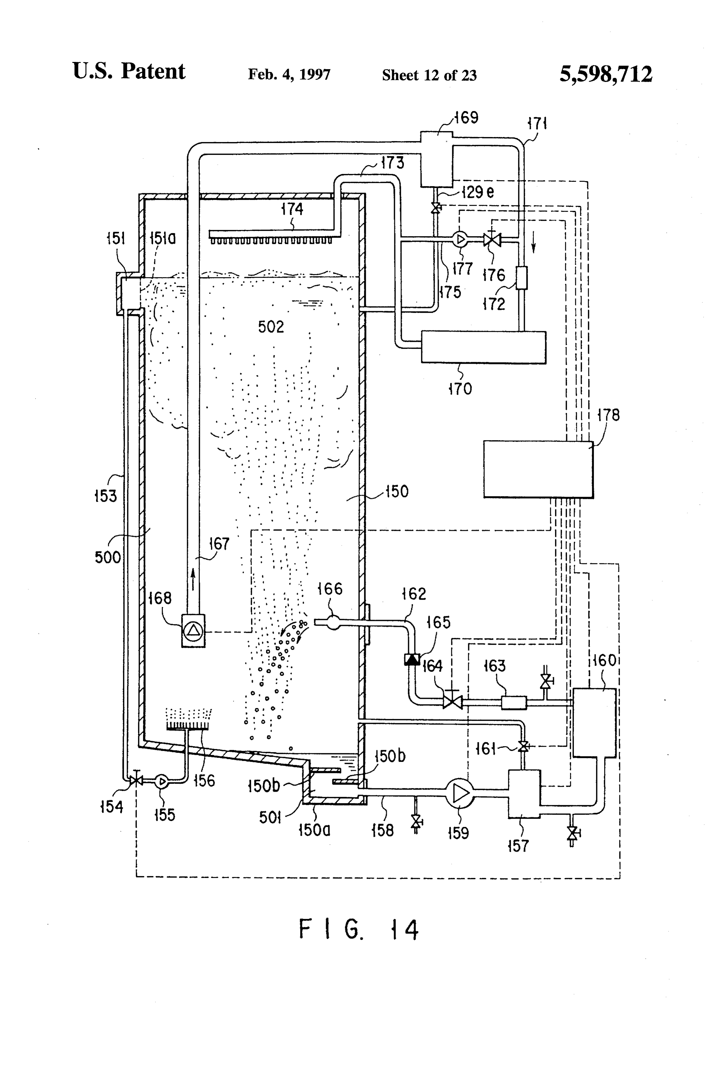
sherbet-state ice 502 which can easily thaw can be stably Further, it is possible to additionally provide the device to made. 15 the conventional water circulating type device as an ice heat As shown in FIGS. 12 and 13, since the inlet port 122b accumulation device for each building, and in this case, not and the outlet port 122c disposed in position lower than the only the effect that ice can be additionally made but also the inlet port 122b are formed in the tank 122a of the water/ effect that a special control is not required and the inspection liquid separation device 122, the refrigerant 501 supplied 20 and maintenance service can be made easy can be attained. from the storage portion 110a of the water tank 110 and fed Next, a latent heat accumulation system according to via the supply pipe 119 is fed into the tank 122a via the inlet another embodiment of this invention is explained with port 122b. At this time, the refrigerant 501 is discharged reference to FIG. 14. FIG. 14 shows the construction of an from the outlet port 122c while making a vortex in the tank ice heat accumulation device disposed on the rooftop of a 122a. Therefore, after the cold water 500 whose specific building. As shown in FIG. 14, a water tank 150 is disposed gravity is small is collected into the center of the vortex by 25 on the rooftop of the building and stores therein cold water the centrifugal separation process, the cold water 500 rises 500 as a first liquid and a refrigerant 501 as a second liquid by the buoyancy thereof and is then discharged from the having a larger specific gravity. The water tank 150 is made outlet port 122c of the tank 122a towards the refrigerator long in the height direction and the bottom surface of the 118. Thus, the refrigerant 501 and the cold water 500 can be water tank has an inclined surface and a storage portion 150a automatically separated from each other with high efficiency 30 for storing the refrigerant 501 is formed in the lower end without using a special separation film or device. portion of the inclined surface. A pair of vortex preventing As shown in FIG. 11, the vortex preventing portion 110b portions 150b each formed of a porous plate for preventing is provided to prevent a vortex from being generated at the occurrence of a vortex caused by introduction of the refrig suction portion when the refrigerant 501 is drawn from the 35 erant 501 are mounted in the storage portion 150a in storage portion 110a of the water tank 110 via the supply different positions in the vertical direction. Further, a plu pipe 119. The vortex preventing portion 110b is disposed rality of water-intank portions 151 are formed on the upper above the storage portion 110a of the water tank 110. The portion of the water tank 150. In the open surface of the vortex preventing portion 110b is formed of a porous plate. water-intake portion 151 which faces the inside portion of Further, the guide 119a for defining the intake direction of the water tank, a separator 151a formed of a wire mesh for the refrigerant 501 is disposed on the inlet port 119a 40 separating the water 500 from ice 502 and drawing out only provided at the front end portion of the supply pipe 119. the water 500 is disposed. An annular water-intake portion Therefore, the necessary depth of the storage portion 110a continuously formed on the peripheral surface of the water can be reduced and the amount of cold water 500 contained tank can be used instead of the water-intake portions. in the refrigerant 501 flowing into the supply pipe 119 can 45 One end portion of a pipe 153 disposed outside the water be significantly reduced. tank to vertically extend is connected to the discharging port As shown in FIGS. 9 and 10, the sherbet-state ice 502 of the water-intake portion 151. The other end portion of the which can easily thaw is stored in the water tank 110. The pipe 153 is connected to a pump 155 via a control valve 154. ice 502 can rapidly thaw by spraying water which is warmed Further, the pump 155 is connected to a water spraying by carrying away heat from the cooling loads in the respec 50 device 156 via a pipe. The pipe passes through the bottom tive rooms or the building onto the sherbet-state ice 502. wall of the water tank in a watertight manner. The water Immediately after the ice 502 has thawed, ice 502 rises spraying device 156 is disposed in position near the bottom towards the surface so that cold water can be rapidly surface in the water tank and above the boundary surface obtained. between the refrigerant 501 and cold water. As described above, according to this embodiment, the 55 A water/liquid separation device 157 is connected to a high efficiency, stable operation, high controllability, sim supply pipe 158 which is connected to the storage portion plicity, high-speed thawing property, direct water-intake 150a via a pump 159. The water/liquid separation device ability and the like which are indispensable conditions for 157 intakes the refrigerant 501 from the storage portion the ice heat accumulation device in the large-scale regional 150a and the refrigerant in the water/liquid separation heat supply plant can be satisfied. That is, in the large-scale 60 device 157 is compressed by the pump 159. The water/liquid regional heat supply plant installed in the underground of the separation device 157 separates water from the compressed midtown area and constructed by a large-capacity heat refrigerant 501 and supplies the refrigerant to a refrigerator pump, water tank, water conveying pumps, flow control 160. The water separated by the water/liquid separation valves, calorimeter and the like, the heat accumulation device 157 is returned into the water tank via a control valve capacity can be increased to several times that of the 65 161.
conventional case by improving the conventional water tank The refrigerator 160 is disposed in the same position level without deteriorating the usability of the plant. Further, in as the water tank 150. The refrigerator 160 serves to cool the
Page 30
refrigerant 501 from which water is removed by the water/ supply plant can be controlled. Further, in this embodiment, liquid separation device 157. A discharging pipe 162 which the open/closed state of the valve 154 is controlled by the is formed to pass through the side wall of the water tank in air-conditioning control device 151. Thus, the water-intake a watertight manner is connected to the refrigerator 160. A portions 151 are controlled to be sequentially activated in flow meter 163, flow control valve 164 and check valve 165 each preset period so as to store the ice 502 uniformly in the are connected in this order to the discharging pipe 162. A water tank. Further, the refrigerant 501 can be automatically nozzle 166 is connected to the end portion of the discharging supplemented by use of a supplementing device (not pipe 162 which is disposed inside the water tank. In this shown).
case, the nozzle 166 has at least one discharging hole. The Next, the operation of the ice heat accumulation device nozzle 166 is disposed in position above the water spraying with the above construction is explained, but the explanation device 156. The nozzle 166 is separated at least 0.5 m from 10 for the same process as explained in the former embodiment the bottom surface of the water tank or the boundary surface is omitted and only the particular process in this embodi between the water and the refrigerant. The direction and discharging speed of the nozzle 166 are determined so as not ment is explained. The ice heat accumulation device with the to prevent the refrigerant 501 discharged from the side above construction shown in this embodiment is effective portion of the water tank from reaching the water spraying 15 when it is used in a place where no limitation is imposed on device 156. Thus, the refrigerant 501 cooled by the refrig the height, for example, when it is disposed on the rooftop erator 160 is injected from the injection nozzle 166 into the of a building since the water tank 150 is made long in the cold water in the water tank 150 via the flow meter 163, flow height direction. That is, the volume of the ice making control valve 164 and check valve 165. portion (a portion below the injection nozzle 166) in the If the operation of the liquid supply pump 159 of the 20 water tank can be made relatively small in comparison with refrigerator 160 is interrupted for some reasons, the cold that of the ice storing portion (a portion above the injection water 500 in the nozzle 166 flows backward in the circu nozzle 166). Therefore, the ice-filled rate can be enhanced. lating system of the cold refrigeration 501. In this case, there Further, when the flow control valve 154 is opened and occurs a possibility that freezing or solidification occurs 25 the pump 155 is operated, water near the sherbet-state ice inside the internal portion of the circulating system. The 502 is sprayed into the water tank by the water spraying check valve 165 is provided to solve the above problem that device 156 and upward flow of water is created in the water freezing or solidification occurs inside the internal portion of tank. Therefore, fine particles of ice 502 are carried by the the circulating system. A cold water supply pipe 167 is flow of water sprayed from the water spraying device 156, formed to pass through the upper portion of the water tank 30 rise to the upper portion of the water tank, and are combined 150 and extend downwardly into the water tank. A water with the assembly of the sherbet-state ice 502. intake pump 168 is mounted on the end portion of the cold Thus, the ice assembly 502 grows, and water sprayed water supply pipe 167 inserted into the water tank. Further, from the returning pipe 174 is passed through the ice the end portion of the cold water supply pipe 167 lying assembly 502 to increase the assembling density of the ice outside the water tank is connected to a separation device 35 assembly. As a result, the filling rate of the ice 502 is 169. Like the water/liquid separation device 157, the sepa increased, thereby enhancing the space efficiency of the ration device 169 utilizes the separation process according to device.
the difference between the densities by use of the centrifugal Cold water drawn by the water-intake pump 168 flows force. When supplied with cold water in the water tank into the separation device 169 via the supply pipe 167. Then, drawn by the water-intake pump 168, the separation device 40 the refrigerant 501 contained in the cold water although 169 removes the refrigerant 501 contained in the received small in amount is separated by application of the centrifu cold water and supplies the cold water to an air-conditioning gal force in the separation device 169 in the same manner as load 170 via a water supply pipe 171. A calorimeter 172 for in the water/liquid separation device 157 and collected. As measuring the amount of heat consumed by the air-condi tioning load 170 is disposed in the water supply pipe 171. 45 aconditioning result, high purity cold water is supplied to the air load 170. Thus, the refrigerant 501 can be
The air-conditioning load 170 is not necessarily limited to a prevented from flowing into the air-conditioning load 170. single system, and in most cases, a plurality of systems are As a result, the ice making operation can be stably effected independently disposed. for a long period of time.
Further, a water spray device 174 is arranged in a space The water subjected to the heat exchange with the air in the upper portion of the water tank 150. The water spray 50 conditioning load 170 is returned to the spraying device 174 device 174 feeds back the cold water subjected to the heat and then sprayed over a wide area on the ice assembly 502. exchange by the air-conditioning load into the water tank via The water intake position by the water-intake pump 168 is a returning pipe 173. The spraying device 174 has a plurality set in substantially the same position as the mounting of cold water spraying ports. position of the injection nozzle 166 so that the thawing The intermediate portion of the water supply pipe 171 for 55 efficiency can be kept high.
connecting the separation device 169 to the air-conditioning Further, the refrigerant 501 is supplied to the refrigerator load 170 is branched. The branched portion is connected to 160 via the water/liquid separation device 157 by the the returning pipe 173 via a bypass pipe 175. A flow control operation of the circulating pump 159. Even if the operation valve 176 and a pump 177 are provided in the pipe 175. The of the circulating pump 159 is interrupted for some reasons pipe 175, flow control valve 176 and pump 177 are com 60 when the refrigerant 501 cooled by the refrigerator 160 is bined to construct a water supply temperature adjusting line. injected into the water tank by the injection nozzle 166, cold An air-conditioning control device 178 controls the above water in the water tank can be prevented from flowing into various pumps, control valve, separator, refrigerator accord the circulating system by the operation of the check valve ing to the temperatures of various points and the position of 165 provided in that portion of the discharging pipe 162 the boundary surface between the refrigerant 501 and water. 65 which lies between the refrigerator 160 and the injection By the above control operation, the air-conditioning in the nozzle 166, thereby making it possible to prevent occurrence building and the operation of the various devices in the heat of solidification in the circulating system.
Page 31
As described above, in this embodiment, the device can Cables 166i are connected to the electric heater 166h so that be safely operated with high efficiency like the first embodi the electric heater can be energized by the external power ment, the controllability is excellent, the construction is source (not shown). In this example, since the electric heater simple, the maintenance is easy, and the thawing efficiency 166h and cables 166i are used in the water, they are is high, and thus an ice heat accumulation device whose waterproofed and the cables 166i are laid mainly inside the usability is high can be obtained. Particularly, the device of heat insulation material 166f of the pipe line and then lead this embodiment is effective when used in a place where no out to the exterior.
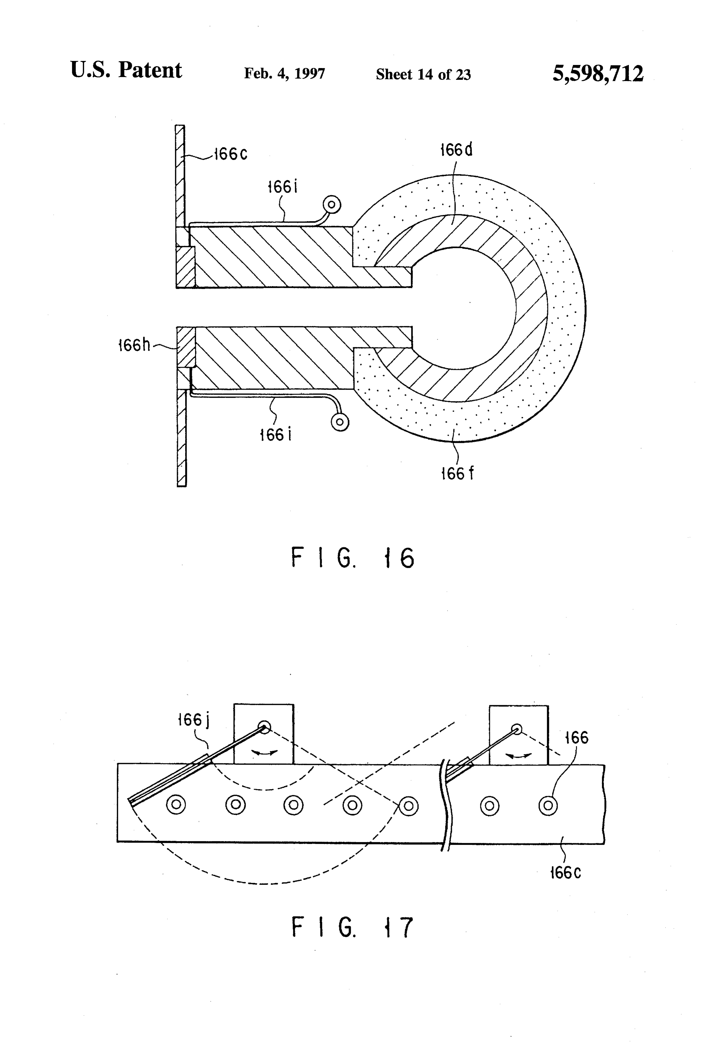
severe limitation is imposed on the height thereof or on the By using the above freezing preventing means and ener rooftop of a building. gizing the electric heater 166h to heat the front end portion Next, in the above embodiment, the measure taken to 10 of the nozzle, the temperature of the front end portion can be prevent freezing in the injecting portion of the injection kept at a temperature higher than the freezing point of the nozzle 166 is explained with reference to FIGS. 15 to 17. In cold water so that the cold water can be prevented from a case where the second liquid (refrigerant) cooled to a being frozen. In this case, the electrical heating may be temperature lower than the solidifying point (freezing point) effected continuously or periodically, but if it is excessively of the first liquid (cold water) is injected into the cold water, 15 heated, the ice making loss occurs, and therefore, it is the temperature of the injecting end portion of the injection desirable to adjust the surface temperature of the electric nozzle is set to the same temperature of the refrigeration if heater 166h to be set several degrees C(C) higher than the no measure is taken. Therefore, the cold water in contact freezing point of the cold water.
with the injecting end portion is frozen. As a result, the ice FIG. 17 shows the structure having a mechanism for 502 starts to grow in a tubular form with the frozen water as 20 mechanically wiping the front end surface of the nozzle as a core. If the condition is kept unchanged, no serious the freezing preventing means for the injection nozzle. As problem will occur, but if fine ice particles formed and shown in FIG. 17, a freezing preventing wiper mechanism suspended in the water of the water tank or curdy combi 166j which is the same as the mechanism for wiping the nation of ice particles is attached to the tubular-form ice 502 while being suspended, the ice further grows, thereby mak 25 plate 166c of windshield a car is disposed on the convection preventing arranged on the front surface of the injection ing a problem. As a result, a large mass of ice 502 is formed nozzle 166.
with the nozzle set at the center. Then, the heat accumulation With the injection nozzle having the above freezing medium of low temperature leaks into the internal portion of preventing means, the ice 502 can be mechanically wiped the nozzle. The ice 502 is hard and low in temperature and away before the cold water freezes and grows on the nozzle has no thawing ability, thereby lowering the ice making 30 portion by always operating the wiper mechanism 166j. efficiency.
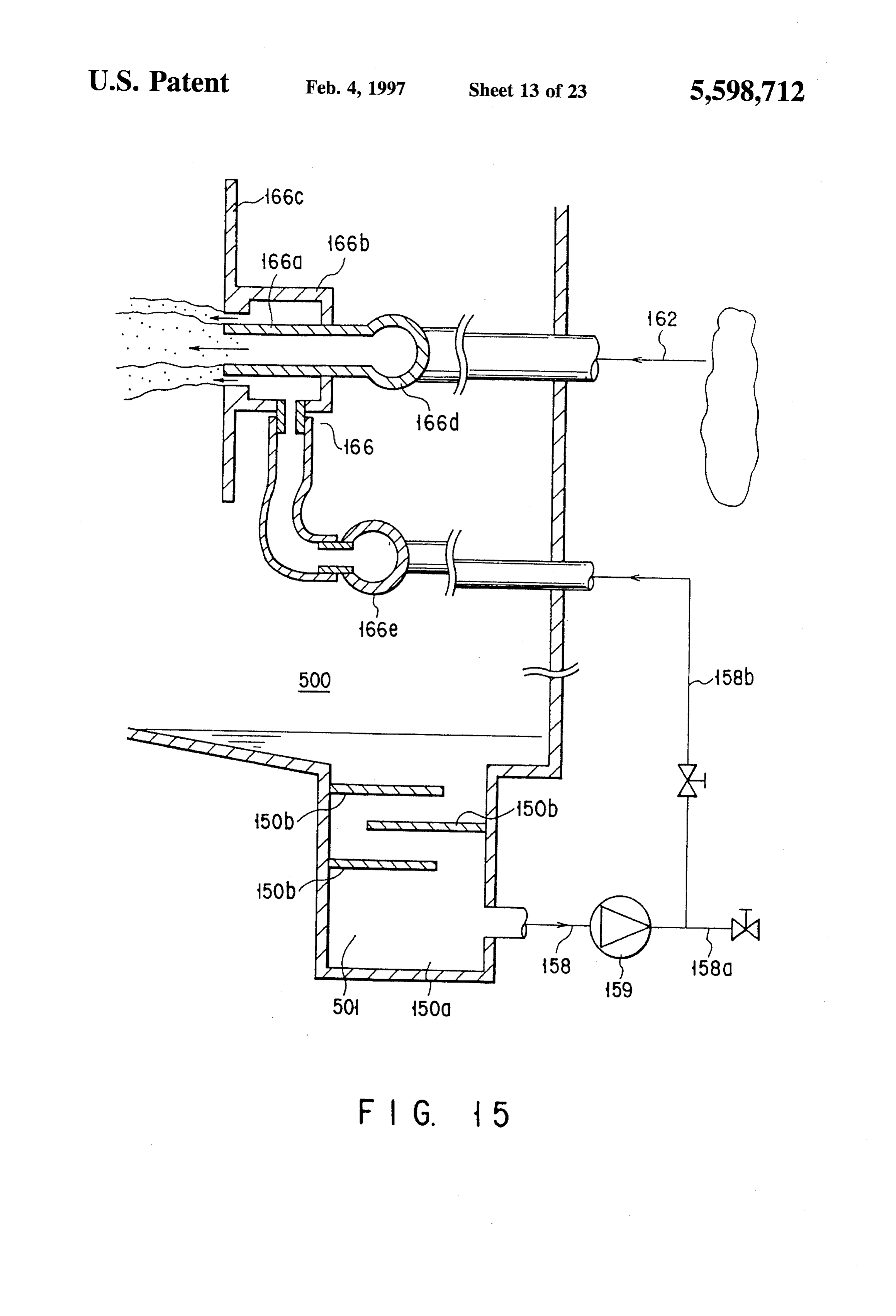
Therefore, it is extremely important to prevent solidifi Thus, adhesion of the ice due to the freezing of the cold water can be prevented. Particularly, the wiper mechanism is cation or freezing of the cold water in the nozzle portion. effective when the electrical heating is not effected. When FIG. 15 shows the structure of a double spraying nozzle with the wiper mechanism 166j is used together with the structure a convection preventing plate and a path for supplying the 35 shown in FIG. 15 or 16, a more significant effect can be refrigerant for the nozzle. As shown in FIG. 15, the supply attained.
system for the refrigerant 501 is constructed by two branch Thus, as shown in FIGS. 15 to 17, the sherbet-state ice lines including a line 158a for supplying the refrigerant which is compressed by the pump 159 to a refrigerator (not 502 can be stably and continuously obtained with high shown) and a line 158b formed to extend to the water tank. 40 cold waterbyonusing efficiency a structure for preventing the freezing of injection nozzle by use of warm fluid, electric
The injection nozzle 166 includes a central nozzle 166a for heater or mechanical wiper.
injecting a refrigerant, an outer nozzle 166b for injecting a refrigerant of relatively high temperature, and a convention Further, this invention is not limited to the constructions preventing plate 166c formed in substantially the same plane shown in the above embodiments, and various modifications as the above nozzles and integrally formed with the outer 45 can be obtained to further enhance the function thereof by nozzle 166b. In this case, a plurality of injection nozzles 166 replacing part of the construction by the other part or adding with the above construction are provided in the water tank. the other part to the construction. Single nozzle headers 166d, 166e for supplying refrigerants Examples of the modifications are explained below. to the respective nozzles may be commonly provided for a (1) In the above embodiment, a fluorinert-series inactive group of nozzles. Further, the line for supplying the refrig 50 liquid which does not contain hydrogen and chlorine erant of low temperature from the refrigerator and the nozzle and has characteristics that the specific gravity is equal portion are thermally insulated. to or larger than 1.7 at 0° C., the solidifying point is When the above freezing preventing means is provided -30° C. or lower and the boiling point is 75° C. or for the injection nozzle 166, the refrigerant of relatively high higher may be used as the second liquid. temperature is injected in such a form to surround the 55 (2) In the above embodiment, a fluorinert-series inactive refrigerant of low temperature. Therefore, the front end magnetic fluid which does not contain hydrogen and portion of the nozzle at the low temperature is not set in chlorine and has characteristics that the specific gravity contact with the cold water, thereby making it possible to is equal to or larger than 1.7 at 0°C., the solidifying prevent the solidification in the nozzle portion by the cold point is -30°C. or lower and the boiling point is 75° C. water attached thereto. 60 or higher may be used as the second liquid. In this case, FIG.16 shows the structure having an electric heater 166h a magnetic field generation device may be disposed as the freezing preventing means for the injection nozzle. near the injection nozzle to speed up separation Like the case of FIG. 15, in the case shown in FIG. 16, the between the magnetic fluid and water. convection preventing plate 166c is disposed in the same (3) In the above embodiment, it is possible to provide a plane as the refrigerant injection nozzle. The electric heater 65 circulating system exclusively used for the first liquid 166his disposed on the frontend portion of the nozzle which for measuring the temperature of water in the water is set in direct contact with the water in the water tank. tank and supplying the water from the water tank to the
Page 32
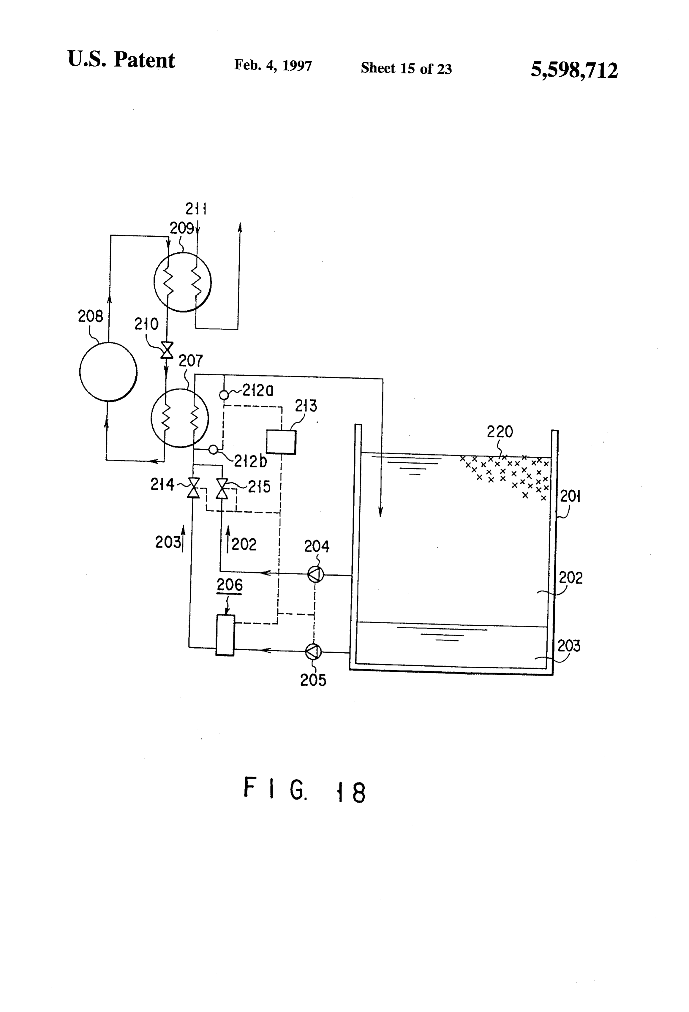
refrigerator, cooling and collecting the water according Next, the operation of the embodiment with the above to the measured temperature. construction is explained. When the temperature of the water (4) In the above embodiment, a supply/collection system 202 in the water tank 201 is high (20° to 30° C), the for supplying the refrigerant cooled by the refrigerator electromagnetic valve 215 is opened and the water pump to a plurality of water tanks is mainly constructed by 204 is driven to draw out the water 202 stored in the water pipes, pumps and switching control valves. The refrig tank 201 and supplies the same to the evaporator 207. At this erant may be supplied/collected to or from the plurality time, the non-freezing liquid pump interrupts its own opera of water tanks simultaneously or with time delay by tion and the electromagnetic valve 214 is closed. The outlet controlling the supply/collection system by use of the temperature (or inlet temperature) of the water 202 of the air-conditioning control device. In this case, the switch 10 evaporator 207 is detected by the temperature detector 212a ing operation of the supply/collection system may be (or temperature detector 212b), and when the detected automatically effected according to the amounts of ice temperature is lowered to a level (which is different accord made and stored in the respective water tanks or a ing to the capacity of the refrigerator and is 3' to 5°C., for signal output from a measuring unit for measuring the example) close to and above the solidifying point of the temperature of water in the water tanks. 15 water 202, the electromagnetic valve 215 is closed, the (5) In the above embodiment, an accumulation mecha operation of the water pump 204 is interrupted, the electro nism for accumulating ice made in the water tank is magnetic valve 214 is opened, and the non-freezing liquid disposed in the water tank. A mixture of water and ice pump 205 is driven to supply the non-freezing liquid 203 which is accumulated by the ice accumulation mecha collected from the lower portion of the water tank 201 nism and whose filling rate is relatively high is fed to 20 directly to the evaporator 207 under the control of the a carrying system constructed by pipes and pumps. control device 213. The cooled non-freezing liquid 203 is Thus, the mixture (fluid) can be fed to a desired directly injected into the water 202 in the water tank 201. As destination, and it becomes possible to feed the ice and a result, the water 202 is cooled and ice 220 is made. When water in the two-phase flow state to a storing water tank the water 202 is accumulated and rises to a high level in the or cooling load disposed at a remote place or high 25 separator 206, the electromagnetic valve 219 is opened to place. drain the water (to the water tank 201 or to the exterior). Next, another embodiment of this invention is explained According to the embodiment with the above structure, in with reference to the accompanying drawings. FIG. 18 is a a case where water of high temperature is cooled, the water view showing the construction of the embodiment of this in the water tank can be rapidly cooled and the performance invention. As shown in FIG. 18, water 202 and a non 30 of the refrigerator can be utilized to the maximum degree freezing liquid (refrigerant) 203 which is not water-soluble since water which is excellent in the heat carrying property and has a specific gravity larger than 1 are stored in a water can be directly supplied to the evaporator. tank 201. A water pump 204 is connected to the side portion This invention is not limited to the above embodiment and of the water tank 201 in an intermediate position in the can be modified as shown in FIG. 20. The embodiment height direction to circulate the water. A non-freezing liquid 35 shown in FIG. 20 is similar to the above embodiment except pump 205 is connected to the side portion of the water tank that an ice maker 221 is disposed in position higher than the 201 in a lower position in the height direction to circulate the water tank 201, the inlet port of a non-freezing liquid pump refrigerant. An evaporator 207, compressor 208, condenser 205 is connected to the bottom portion of the ice maker 221, 209 and expansion valve 210 constitute the main portion of a pipe is disposed on the outlet port side of the water pump the refrigerator. The heat of cold water 211 is radiated via a 40 204 to extend in parallel to the pipe connected to the radiator (not shown) of the condenser 207. The non-freezing evaporator 207, and the pipe is connected to the ice maker liquid pump 205 is connected to the evaporator 309 via a 221 via an electromagnetic valve 222. The inlet port side of separation tank 206 and electromagnetic valve 214. The the water pump 204 is connected to the side portion of the water pump 204 is connected to the evaporator 207 via an water pump 204 in a lower position in the height direction. electromagnetic valve 215. A temperature detector 212a 45 The compressor, condenser and expansion valve are not serves to detect the temperature of water 202 in the outlet shown.
port of the evaporator 207. A temperature detector 2.12b Next, the operation of the embodiment is explained. serves to detect the temperature of water 202 in the inlet port When the temperature of the water 202 in the water tank 201 of the evaporator 207. A reference numeral 203 denotes a is high (20° to 30° C), the electromagnetic valve 215 is control device. 50 opened and the water pump 204 is driven to draw out the The separator 206 has a porous floating plate 217 which water 202 from the side portion of the water tank 201 and is formed of a material having a specific gravity smaller than supply the same to the evaporator 207 which in turn cools that of the non-freezing liquid 203 and larger than that of the the received water, and the thus cooled water is fed into the water 202 and is set to floatin the boundary surface between water tank 201 via the ice maker 221. At this time, the the water 202 and non-freezing liquid 203 in a tank 216 as 55 electromagnetic valve 214 is closed. Like the case of the shown in FIG. 19. When water 202 is accumulated in the above embodiment, when the temperature detected by the tank 216 and the floating plate 217 sinks and reaches a preset temperature detector 212a (or temperature detector 212b) is height, the position of the floating plate is detected by a lowered to a level close to and above the solidifying point of detector 218. Then, the detector outputs a signal to cause the the water, the electromagnetic valve 215 is closed and the control device 213 to open an electromagnetic valve 219 60 electromagnetic valve 222 is opened to supply the water 202 disposed on the upper portion of the tank 216, thereby into the ice maker 221. Next, the electromagnetic valve 214 draining the water. Pipes respectively connected to the is opened and the non-freezing liquid pump 205 is driven to non-freezing liquid pump 205 and electro-magnetic valve supply the non-freezing liquid 203 collected from the lower 214 are provided in the lower portion of the tank 216. portion of the ice maker 221 to the evaporator 207. The Further, an opening (not shown) which is in communication 65 non-freezing liquid 203 cooled in the evaporator 207 is with an the atmosphere is formed in the upper wall of the injected into the ice maker 221 so as to be brought into tank 216. contact with the water 202, and as a result, the water 202
Page 33
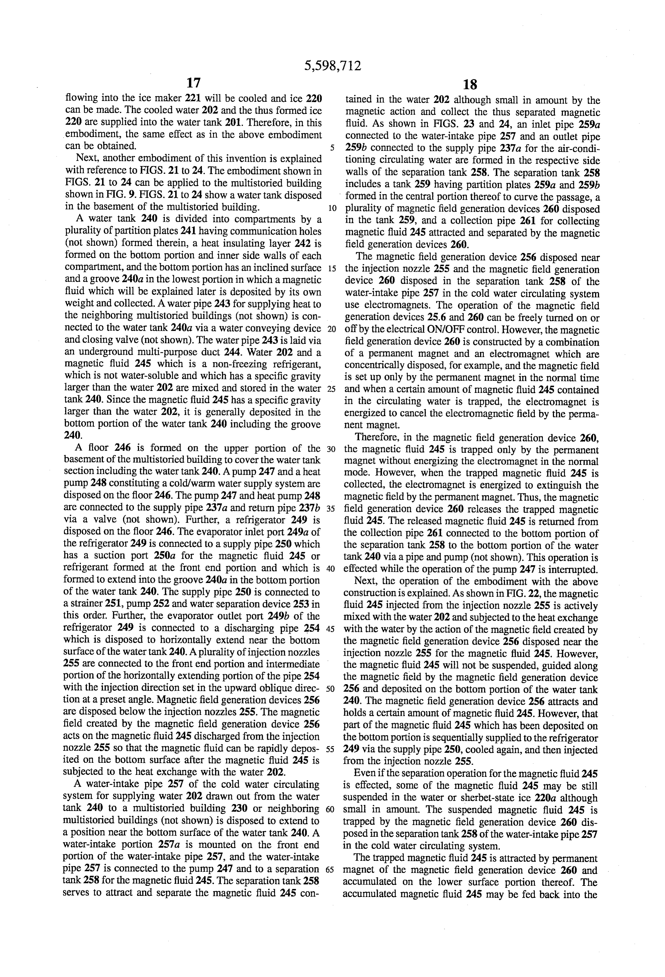
flowing into the ice maker 221 will be cooled and ice 220 tained in the water 202 although small in amount by the can be made. The cooled water 202 and the thus formed ice magnetic action and collect the thus separated magnetic 220 are supplied into the water tank 201. Therefore, in this fluid. As shown in FIGS. 23 and 24, an inlet pipe 259a embodiment, the same effect as in the above embodiment connected to the water-intake pipe 257 and an outlet pipe can be obtained. 259b connected to the supply pipe 237a for the air-condi Next, another embodiment of this invention is explained tioning circulating water are formed in the respective side with reference to FIGS. 21 to 24. The embodiment shown in walls of the separation tank 258. The separation tank 258 FIGS. 21 to 24 can be applied to the multistoried building includes a tank 259 having partition plates 259a and 259b shown in FIG. 9. FIGS. 21 to 24 show a water tank disposed formed in the central portion thereof to curve the passage, a in the basement of the multistoried building. 10 plurality of magnetic field generation devices 260 disposed A water tank 240 is divided into compartments by a in the tank 259, and a collection pipe 261 for collecting plurality of partition plates 241 having communication holes magnetic fluid 245 attracted and separated by the magnetic (not shown) formed therein, a heat insulating layer 242 is field generation devices 260.
formed on the bottom portion and inner side walls of each The magnetic field generation device 256 disposed near compartment, and the bottom portion has an inclined surface 15 the injection nozzle 255 and the magnetic field generation and a groove 24.0a in the lowest portion in which a magnetic device 260 disposed in the separation tank 258 of the fluid which will be explained later is deposited by its own water-intake pipe 257 in the cold water circulating system weight and collected. A water pipe 243 for supplying heat to use electromagnets. The operation of the magnetic field the neighboring multistoried buildings (not shown) is con generation devices 25.6 and 260 can be freely turned on or nected to the water tank 240a via a water conveying device 20 off by the electrical ON/OFF control. However, the magnetic and closing valve (not shown). The water pipe 243 is laid via field generation device 260 is constructed by a combination an underground multi-purpose duct 244. Water 202 and a of a permanent magnet and an electromagnet which are magnetic fluid 245 which is a non-freezing refrigerant, concentrically disposed, for example, and the magnetic field which is not water-soluble and which has a specific gravity is set up only by the permanent magnet in the normal time larger than the water 202 are mixed and stored in the water 25 and when a certain amount of magnetic fluid 245 contained tank 240. Since the magnetic fluid 245 has a specific gravity in the circulating water is trapped, the electromagnet is larger than the water 202, it is generally deposited in the energized to cancel the electromagnetic field by the perma bottom portion of the water tank 240 including the groove nent magnet.
240. Therefore, in the magnetic field generation device 260, A floor 246 is formed on the upper portion of the 30 the magnetic fluid 245 is trapped only by the permanent basement of the multistoried building to cover the water tank magnet without energizing the electromagnet in the normal section including the water tank 240. A pump 247 and a heat mode. However, when the trapped magnetic fluid 245 is pump 248 constituting a cold?warm water supply system are collected, the electromagnet is energized to extinguish the disposed on the floor 246. The pump 247 and heat pump 248 magnetic field by the permanent magnet. Thus, the magnetic are connected to the supply pipe 237a and return pipe 237b 35 field generation device 260 releases the trapped magnetic via a valve (not shown). Further, a refrigerator 249 is fluid 245. The released magnetic fluid 245 is returned from disposed on the floor 246. The evaporator inlet port 249a of the collection pipe 261 connected to the bottom portion of the refrigerator 249 is connected to a supply pipe 250 which the separation tank 258 to the bottom portion of the water has a suction port 250a for the magnetic fluid 245 or tank 240 via a pipe and pump (not shown). This operation is refrigerant formed at the front end portion and which is 40 effected while the operation of the pump 247 is interrupted. formed to extend into the groove 24.0a in the bottom portion Next, the operation of the embodiment with the above of the water tank 240. The supply pipe 250 is connected to construction is explained. As shown in FIG.22, the magnetic a strainer 251, pump 252 and water separation device 253 in fluid 245 injected from the injection nozzle 255 is actively this order. Further, the evaporator outlet port 249b of the mixed with the water 202 and subjected to the heat exchange refrigerator 249 is connected to a discharging pipe 254 45 with the water by the action of the magnetic field created by which is disposed to horizontally extend near the bottom the magnetic field generation device 256 disposed near the surface of the water tank 240. A plurality of injection nozzles injection nozzle 255 for the magnetic fluid 245. However, 255 are connected to the front end portion and intermediate the magnetic fluid 245 will not be suspended, guided along portion of the horizontally extending portion of the pipe 254 the magnetic field by the magnetic field generation device with the injection direction set in the upward oblique direc 50 256 and deposited on the bottom portion of the water tank tion at a preset angle. Magnetic field generation devices 256 240. The magnetic field generation device 256 attracts and are disposed below the injection nozzles 255. The magnetic holds a certain amount of magnetic fluid 245. However, that field created by the magnetic field generation device 256 part of the magnetic fluid 245 which has been deposited on acts on the magnetic fluid 245 discharged from the injection the bottom portion is sequentially supplied to the refrigerator nozzle 255 so that the magnetic fluid can be rapidly depos 55 249 via the supply pipe 250, cooled again, and then injected ited on the bottom surface after the magnetic fluid 245 is from the injection nozzle 255.
subjected to the heat exchange with the water 202. Even if the separation operation for the magnetic fluid 245 A water-intake pipe 257 of the cold water circulating is effected, some of the magnetic fluid 245 may be still system for supplying water 202 drawn out from the water suspended in the water or sherbet-state ice 220a although tank 240 to a multistoried building 230 or neighboring 60 small in amount. The suspended magnetic fluid 245 is multistoried buildings (not shown) is disposed to extend to trapped by the magnetic field generation device 260 dis a position near the bottom surface of the water tank 240. A posed in the separation tank 258 of the water-intake pipe 257 water-intake portion 257a is mounted on the front end in the cold water circulating system.
portion of the water-intake pipe 257, and the water-intake The trapped magnetic fluid 245 is attracted by permanent pipe 257 is connected to the pump 247 and to a separation 65 magnet of the magnetic field generation device 260 and tank 258 for the magnetic fluid 245. The separation tank 258 accumulated on the lower surface portion thereof. The serves to attract and separate the magnetic fluid 245 con accumulated magnetic fluid 245 may be fed back into the
Page 34
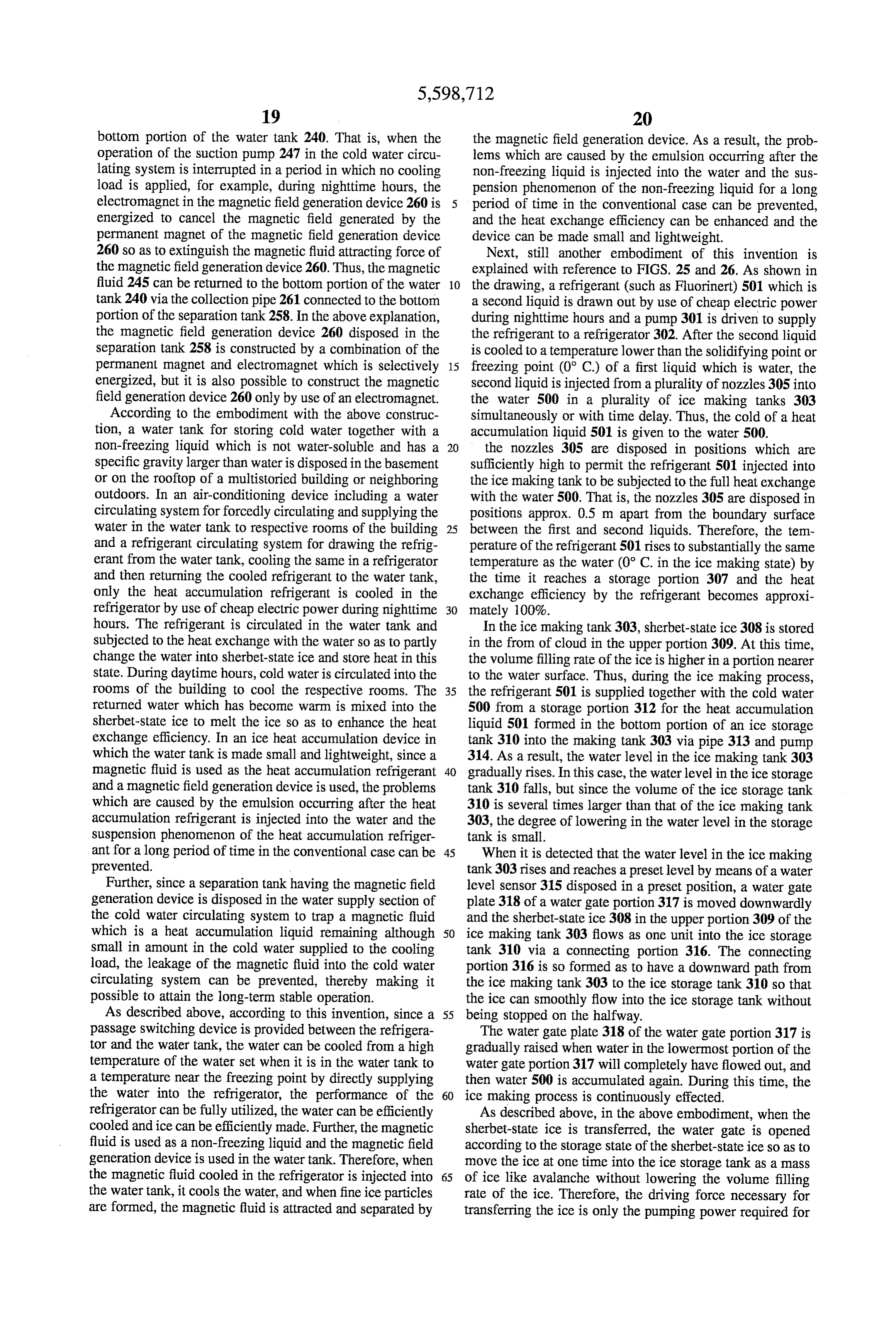
bottom portion of the water tank 240. That is, when the the magnetic field generation device. As a result, the prob operation of the suction pump 247 in the cold water circu lems which are caused by the emulsion occurring after the lating system is interrupted in a period in which no cooling non-freezing liquid is injected into the water and the sus load is applied, for example, during nighttime hours, the pension phenomenon of the non-freezing liquid for a long electromagnet in the magnetic field generation device 260 is period of time in the conventional case can be prevented, energized to cancel the magnetic field generated by the and the heat exchange efficiency can be enhanced and the permanent magnet of the magnetic field generation device device can be made small and lightweight. 260 so as to extinguish the magnetic fluid attracting force of Next, still another embodiment of this invention is the magnetic field generation device 260. Thus, the magnetic explained with reference to FIGS. 25 and 26. As shown in fluid 245 can be returned to the bottom portion of the water 10 the drawing, a refrigerant (such as Fluorinert) 501 which is tank 240 via the collection pipe 261 connected to the bottom a second liquid is drawn out by use of cheap electric power portion of the separation tank 258. In the above explanation, during nighttime hours and a pump 301 is driven to supply the magnetic field generation device 260 disposed in the the refrigerant to a refrigerator 302. After the second liquid separation tank 258 is constructed by a combination of the is cooled to a temperature lower than the solidifying point or permanent magnet and electromagnet which is selectively 15 freezing point (0°C) of a first liquid which is water, the energized, but it is also possible to construct the magnetic second liquid is injected from a plurality of nozzles 305 into field generation device 260 only by use of an electromagnet. the water 500 in a plurality of ice making tanks 303 According to the embodiment with the above construc simultaneously or with time delay. Thus, the cold of a heat tion, a water tank for storing cold water together with a accumulation liquid 501 is given to the water 500. non-freezing liquid which is not water-soluble and has a 20 the nozzles 305 are disposed in positions which are specific gravity larger than water is disposed in the basement sufficiently high to permit the refrigerant 501 injected into or on the rooftop of a multistoried building or neighboring the ice making tank to be subjected to the full heat exchange outdoors. In an air-conditioning device including a water with the water 500. That is, the nozzles 305 are disposed in circulating system for forcedly circulating and supplying the positions approx. 0.5 m apart from the boundary surface water in the water tank to respective rooms of the building 25 between the first and second liquids. Therefore, the tem and a refrigerant circulating system for drawing the refrig perature of the refrigerant 501 rises to substantially the same erant from the water tank, cooling the same in a refrigerator temperature as the water (0°C. in the ice making state) by and then returning the cooled refrigerant to the water tank, the time it reaches a storage portion 307 and the heat only the heat accumulation refrigerant is cooled in the exchange efficiency by the refrigerant becomes approxi refrigerator by use of cheap electric power during nighttime 30 mately 100%.
hours. The refrigerant is circulated in the water tank and In the ice making tank 303, sherbet-state ice 308 is stored subjected to the heat exchange with the water so as to partly in the from of cloud in the upper portion 309. At this time, change the water into sherbet-state ice and store heat in this the volume filling rate of the ice is higher in a portion nearer state. During daytime hours, cold water is circulated into the to the water surface. Thus, during the ice making process, rooms of the building to cool the respective rooms. The 35 the refrigerant 501 is supplied together with the cold water returned water which has become warm is mixed into the 500 from a storage portion 312 for the heat accumulation sherbet-state ice to melt the ice so as to enhance the heat liquid 501 formed in the bottom portion of an ice storage exchange efficiency. In an ice heat accumulation device in tank 310 into the making tank 303 via pipe 313 and pump which the water tank is made small and lightweight, since a 314. As a result, the water level in the ice making tank 303 magnetic fluid is used as the heat accumulation refrigerant 40 gradually rises. In this case, the water level in the ice storage and a magnetic field generation device is used, the problems tank 310 falls, but since the volume of the ice storage tank which are caused by the emulsion occurring after the heat 310 is several times larger than that of the ice making tank accumulation refrigerant is injected into the water and the 303, the degree of lowering in the water level in the storage suspension phenomenon of the heat accumulation refriger tank is small.
ant for a long period of time in the conventional case can be 45 When it is detected that the water level in the ice making prevented. tank 303 rises and reaches a preset level by means of a water Further, since a separation tank having the magnetic field level sensor 315 disposed in a preset position, a water gate generation device is disposed in the water supply section of plate 318 of a water gate portion 317 is moved downwardly the cold water circulating system to trap a magnetic fluid and the sherbet-state ice 308 in the upper portion 309 of the which is a heat accumulation liquid remaining although 50 ice making tank 303 flows as one unit into the ice storage small in amount in the cold water supplied to the cooling tank 310 via a connecting portion 316. The connecting load, the leakage of the magnetic fluid into the cold water portion 316 is so formed as to have a downward path from circulating system can be prevented, thereby making it the ice making tank 303 to the ice storage tank 310 so that possible to attain the long-term stable operation. the ice can smoothly flow into the ice storage tank without As described above, according to this invention, since a 55 being stopped on the halfway.
passage switching device is provided between the refrigera The water gate plate 318 of the water gate portion 317 is tor and the water tank, the water can be cooled from a high gradually raised when water in the lowermost portion of the temperature of the water set when it is in the water tank to water gate portion 317 will completely have flowed out, and a temperature near the freezing point by directly supplying then water 500 is accumulated again. During this time, the the water into the refrigerator, the performance of the 60 ice making process is continuously effected. refrigerator can be fully utilized, the water can be efficiently As described above, in the above embodiment, when the cooled and ice can be efficiently made. Further, the magnetic sherbet-state ice is transferred, the water gate is opened fluid is used as a non-freezing liquid and the magnetic field according to the storage state of the sherbet-state ice so as to generation device is used in the water tank. Therefore, when move the ice at one time into the ice storage tank as a mass the magnetic fluid cooled in the refrigerator is injected into 65 of ice like avalanche without lowering the volume filling the water tank, it cools the water, and when fine ice particles rate of the ice. Therefore, the driving force necessary for are formed, the magnetic fluid is attracted and separated by transferring the ice is only the pumping power required for
Page 35
transferring water from the ice storage tank to the ice making ing liquid 370 is put in a lower part thereof, the water 380 tank, and since the mechanism of upward or downward is placed above the antifreezing liquid 370, and the flock ice movement of the water gate plate is used to permit the 390a forms above the water 380. The flock ice 390a is sherbet-state ice to move by its own weight, it is not transferred to a remote place via the upward pipe 350d and necessary to transfer the ice without using a complicated transfer pipe 354. In the context of this description, the water transferring means. Further, if the water gate is formed to be 380 includes drinking water, non-drinking water and sea long in the horizontal direction, it becomes possible to Water.
prevent the ice from being unwantedly broken and prevent The hopper section 350b and liquid reservoir section 350c water from separately flowing into the ice storage tank. formed at the lower part of the ice-producing tank 350 In the above-described latent heat accumulation systems O recover the antifreezing liquid 370 descending within the shown in FIGS. 8 to 24 which are not provided with ice ice-producing and ice 390 tank 350. A two-phase stream of the water 380 rises through the upward pipe 350d coupled to transferring mechanisms and in a latent heat accumulation the upper part of the ice-producing tank 350. The two-phase system having an ice transferring mechanism as shown in stream is transferred to a specified place via the transfer pipe FIGS. 25 and 26, a second fluid, which does not combine 354 coupled to the upward pipe 350d. The two-phase stream with a first fluid, has a specific gravity greater than that of 15 transferred via the transfer pipe 354 is put in a reservoir tank the first fluid and is cooled to a preset temperature level is 356 via a discharge section 355. injected into the first fluid. Thus, a solid phase material of The system of this embodiment includes a water circula the first fluid is produced by the solidification phenomenon tion system. The water circulation system comprises a pipe and the latent heat of the solid phase material is used to cool 359 and a pressure pump 360. The water 380 is output from a to-be-cooled object. Specifically, these latent heat accu 20 the reservoir tank 356 via the pipe 359 and pressurized by mulation systems employ, as a heat medium, an antifreezing the pressure pump 360. The pressurized water 380 is input fluid such as an oily liquid or a fluorine-based inactive liquid to the ice-producing tank 350.
which is non-water-soluble, has a greater specific gravity The system of this embodiment also includes an antifreez than water, and is cooled to 0°C. or below by arefrigerating ing liquid circulation system. The antifreezing liquid circu machine. The antifreezing fluid is, for example, a two 25 lation system comprises a pipe 351, a pressure pump 352 element liquid of fluorine and carbon, e.g. Fluorinate (trade and arefrigerator 353. The antifreezing liquid 370 recovered name). The antifreezing liquid is injected into water in a from a recovery section 350b, 350c via the pipe 351 is water tank, and heat exchange is carried out by direct contact cooled by the refrigerator 353 and the cooled antifreezing between the antifreezing liquid and the water. By the heat liquid 370 is pressurized by the pressure pump 352. The exchange, part of the wateris stored as sherbet-state ice. The 30 pressurized antifreezing liquid 370 is injected from a nozzle antifreezing liquid is recovered from a lower part of the 353 into the wafer 380 within the ice-producing tank 350, water tank and ice production is continued. and put in direct contact with the water 380. Attention has been paid to the fluidity of the sherbet-state The ice-producing tank 350, hopper section 350b, liquid ice produced in the latent heat accumulation system adopt reservoir section 350c, upward pipe 350d and transfer pipe ing the above ice producing method, and various systems 35 354 are connected in a sealed state.
have been devised for transferring the ice along with water The nozzle 351a is fixed in a predetermined position at a to a remote place. The system shown in FIGS. 25 and 26 is predetermined distance above an interface of the water 380 an example of the latent heat accumulation system having and antifreezing liquid 370 within the ice-producing tank the ice-transferring mechanism. 350 so that maximum heat exchange can be performed In these systems, however, when sherbet-state ice stored 40 between the water 380 and antifreezing liquid 370. The in an ice storing tank is fed to a pump, i.e. when sherbet-state nozzle 351a includes a freeze-preventing mechanism on an ice floating in a water tank is collected and fed to a pump, as-needed basis. The freeze-preventing mechanism may water alone enters the pump smoothly and the ice does not comprise, for example, an electric heat source or a combus smoothly enter the pump. tion heat source of natural gas. The present system includes Embodiments which will be described below relate to 45 a heat exchange system. The heat exchange system com latent heat accumulation systems having ice-transferring prises a pipe 357 and a heat exchanger 358. The cooled mechanisms in which the above problem has been solved. water 380 is taken out from the reservoir tank 356 via the Specifically, these systems are provided with highly reliable, pipe 357 and fed into the heat exchanger 358. The heat highly efficient ice-transferring mechanisms wherein sher exchanged water from the heat exchanger 358 returns to the bet-state ice can be smoothly fed to a pipe and transferred by 50 reservoir tank 356. The heat exchanger 358 is used as an a pump. air-conditioner in buildings.
FIG.27 is a schematic diagram showing a second embodi In addition, the system of this embodiment includes a ment of a latent heat accumulation system having an ice pulverizer 361 for pulverizing the flock ice within the transferring mechanism according to the present invention. upward pipe 350d, in particular, a mass of ice portions, and This system is provided with an ice-producing tank 350. The 55 a driver 361 a for driving the pulverizer 361. ice-producing tank 350 comprises an ice-producing unit FIG. 28 is a schematic diagram showing a third embodi 350a, a hopper unit 350b, a liquid reservoir section 350c, an ment of a latent heat accumulation system having an ice upward pipe 350d and a coupling section 350e. The coupling transferring mechanism according to the present invention. section 350e is coupled to a transfer pipe 354. In the As is shown in FIG. 28, a top portion 401a of an ice-producing tank 350, water 380 is put in direct contact 60 ice-producing column 401 is provided with an antifreezing with an antifreezing liquid 370 which does not combine with liquid nozzle 402 such that an outlet end portion 402a is a first fluid, has a specific gravity greater than water and is situated downward. The outlet end portion 402a of the cooled to a preset temperature level. Thus, a mass of solid antifreezing liquid nozzle 402 is provided with an electric phase material of the water 380, that is, a fine ice 390 (a flock heater 403 for preventing formation of ice at the tip of the ice 390a), is produced. The principle of producing the flock 65 nozzle 402. A water nozzle 404 for jetting water is provided ice 390a is the same as that in the embodiments shown in near the antifreezing liquid nozzle 402 at the top portion FIGS. 8 to 26. In the ice-producing tank 350, the antifreez 401a.
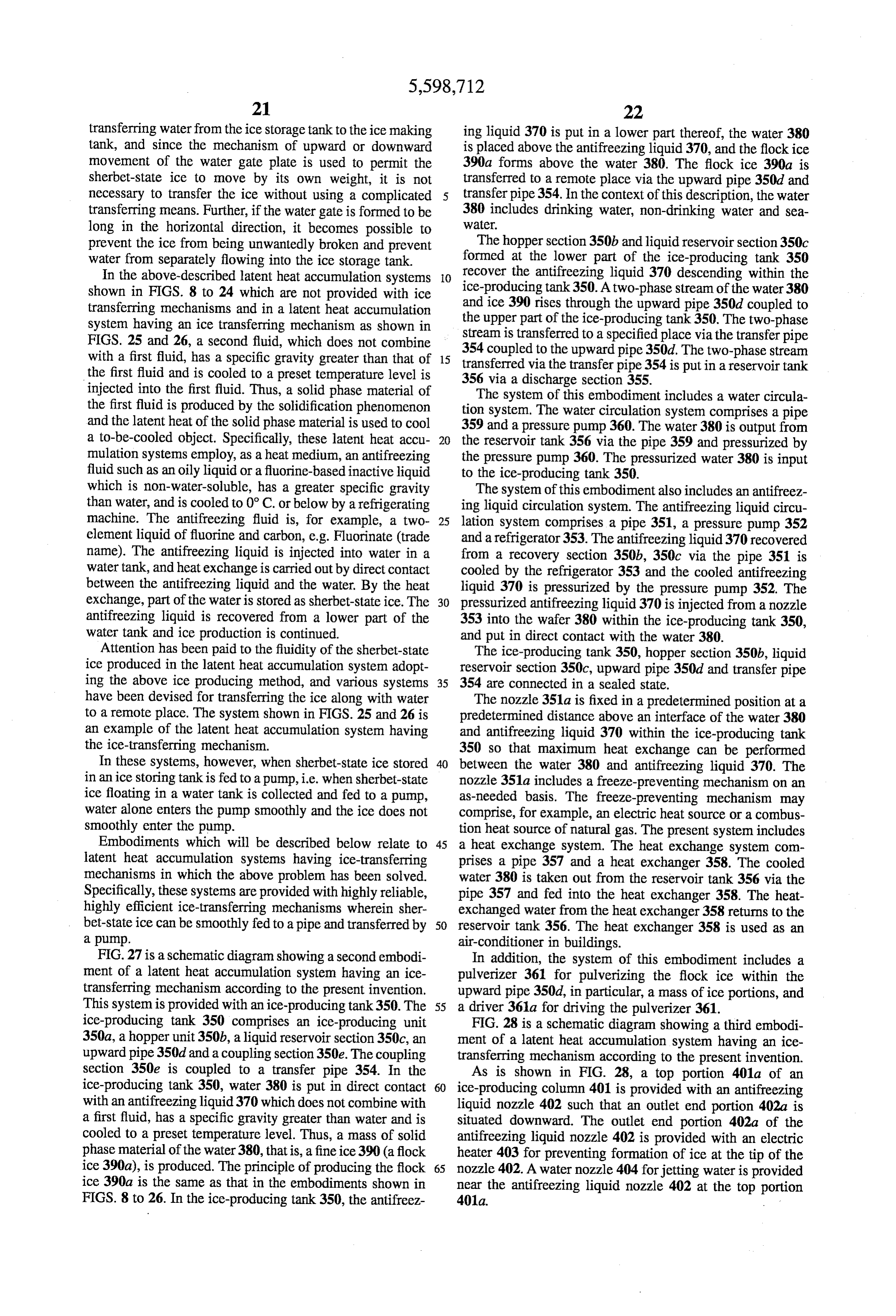
Page 36
An antifreezing liquid recovery section 405 is hermeti In the latent heat accumulation system having the above cally coupled to the lower part of the ice-producing column ice transfer mechanism, the ice-producing column 401, 401. The recovery section 405 stores antifreezing liquid 406 antifreezing liquid recovery section 405, upward pipe 413, such as an oily liquid or a fluorine-based inactive liquid, latent heat accumulation tank 420 and the pipes connecting which is jetted from the antifreezing liquid nozzle 402 into these elements are fully heat-insulated. In addition, the the ice-producing column 401. The antifreezing liquid 406 is ice-producing section 419 is separated from the latent heat non-water-soluble and has a greater specific gravity than accumulation tank 420, and an auxiliary pump is provided water. A pump 407, a flow rate control valve 409 and a midway along the transfer pipe 421 and return pipe 422, refrigerator 410 are connected between the antifreezing when a long-distance circulation is required. liquid recovery section 405 and antifreezing liquid nozzle 10 The operation of the latent heat accumulation system 402 by means of an antifreezing liquid pipe 411. The pump having the ice transferring mechanism according to the third 407, flow rate control valve 409, refrigerator 410 and embodiment will now be described. antifreezing liquid pipe 411 constitute an antifreezing liquid When the antifreezing liquid pump 407 of the antifreezing circulation system. liquid circulation system is driven, the antifreezing liquid is A measuring device 412 for measuring an interface posi jetted downward within the ice-producing column 401 from tion between the antifreezing liquid 406 and water is 15 the antifreezing liquid nozzle 402 provided at the top portion attached to the upper part of the antifreezing liquid recovery 401a of the ice-producing column 401. On the other hand, section 405. The measuring device 412 outputs a detection when the transfer pump 416 of the water circulation system signal to control the antifreezing liquid pump 407 or flow is driven, the water pressurized by the transfer pump 416 rate control valve 409 and, where necessary, order the flows into the top portion of the ice-producing column 401 additional supply of the antifreezing liquid from an anti 20 from the water nozzle 404. Upon the activation of the freezing liquid tank (not shown). antifreezing pump 407 and transfer pump 416, the pressur A vertically situated upward pipe 413 hermetically con ized water along with the antifreezing liquid flows down in nects an upper part of the antifreezing liquid recovery the ice-producing column. In the ice-producing column 401, section 405 and a lower part of the ice-producing column the water is cooled by direct contact with the low-tempera 401. The direction of extension of the downstream portion of 25 ture antifreezing liquid. Thus, ice similar to frazil ice, the upward pipe 413 is changed from the vertical direction observed in rivers and lakes in North America and Europe, to the horizontal direction. A water extraction device 414 is is produced. The frazil ice is a single crystal of ice having a provided on the downstream side of the upward pipe 413. thin, disk-like shape with a diameter of several millimeters. A two-phase stream of ice and water rises in the upward The produced fine ice particles flow down along with the pipe 413 and then flows in the horizontal direction. The 30 surrounding water stream. In this case, the antifreezing water extraction device 414 extracts water from the two liquid with a high specific gravity descends more quickly phase stream of ice and water. The water extracted by the than the surrounding water stream and reaches the antifreez water extraction device 414 is guided to a transfer pump 416 ing liquid recovery section 405 provided below. The via an extracted water pipe 415. The extracted water is descending antifreezing liquid joins the antifreezing liquid supplied from the transfer pump 416 to the water nozzle 404 35 406 staying in the antifreezing liquid recovery section 405. as pressurized water. The water stream including ice cannot descend below the The water extraction device 414 is provided with a antifreezing liquid 406. Accordingly, the direction of the two-phase stream filling rate measuring device 417 for flowing water and ice changes at the interface of the anti measuring the filling rate of ice after water is extracted. The freezing liquid and the water and ice in a communication degree of opening of a pressure reducing valve 418 is 40 section 401a between the ice-producing column 401 and adjusted on the basis of a detection signal from the filling upward pipe 413. Then, the water and ice flow through the rate measuring device 417. By the adjustment of the degree upward pipe 413.
of opening of the pressure reducing valve 418, the flow rate The water including fine ice particles, which has entered of water supplied to the transfer pump 416 via the extracted the upward pipe, rises slowly in the upward pipe 413. In this water pipe 415 is controlled. 45 case, the antifreezing liquid mixed in the water cannot move A pulverizer 424 is provided within the upward pipe 413. along with the water due to the effect of gravitation, and the The pulverizer 424 pulverizes the flock ice rising in the separation of the antifreezing liquid is accelerated. Water upward pipe 413, in particular, a mass of ice portions. The alone of the two-phase stream of ice and water, which has pulverizer 424 is driven by a driver 424a provided outside risen in the upward pipe 413, is extracted by the water the upward pipe 413. The above-described elements and 50 extraction device 414 provided at a downstream-side hori pipes constitute an ice-producing section 419. Zontal portion. As a result, the ice filling rate of the ice/water On the other hand, a latent heat accumulation tank 420 is two-phase stream to the transfer pipe 421 is increased by the situated apart from the ice-producing section. The two-phase water extraction device 414.
stream of ice and water rising through the upward pipe 413 Since the flow rate of the two-phase stream passing is transferred toward the latent heat accumulation tank 420 55 through the transfer pipe 421 is reduced, there is a concern via a transfer pipe 421 and let to fall into the tank 420 from about a decrease in cooling performance. However, since the an open end portion 421a of the pipe 421. heat used for cooling is mainly the latent heat of the ice, the A water port 420a is provided at a lower part of the cooling performance is not greatly decreased. accumulation tank 420. Water in the tank 420 is guided from When the ice/water two-phase stream has reached from the water port 420a to the transfer pump 46 via a return pipe 60 the upward pipe 413 to the latentheat accumulation tank 420 422. The water from the water port 420a and the water from via the transfer pipe 421, the two-phase stream falls by the water extraction device 414 flow commonly into the gravitation from the open end portion 421a of transfer pipe transfer pump 416. The water from the water port 420a and 421 into the upper space of the tank 420. Thus, sherbet-state the water from the water extraction device 414 are fed from ice is successively poured on the ice stored in the tank 420. the transfer pump 416 to the water nozzle 4 as pressurized 65 At this time, the ice stored in the latent heat accumulation water. A water circulation system is constituted by the water tank 420 and newly poured sherbet-state ice are compressed. port 420a, return pipe 422, transfer pump 416, etc. Thereby, the ice filling rate in the tank 420 is increased.
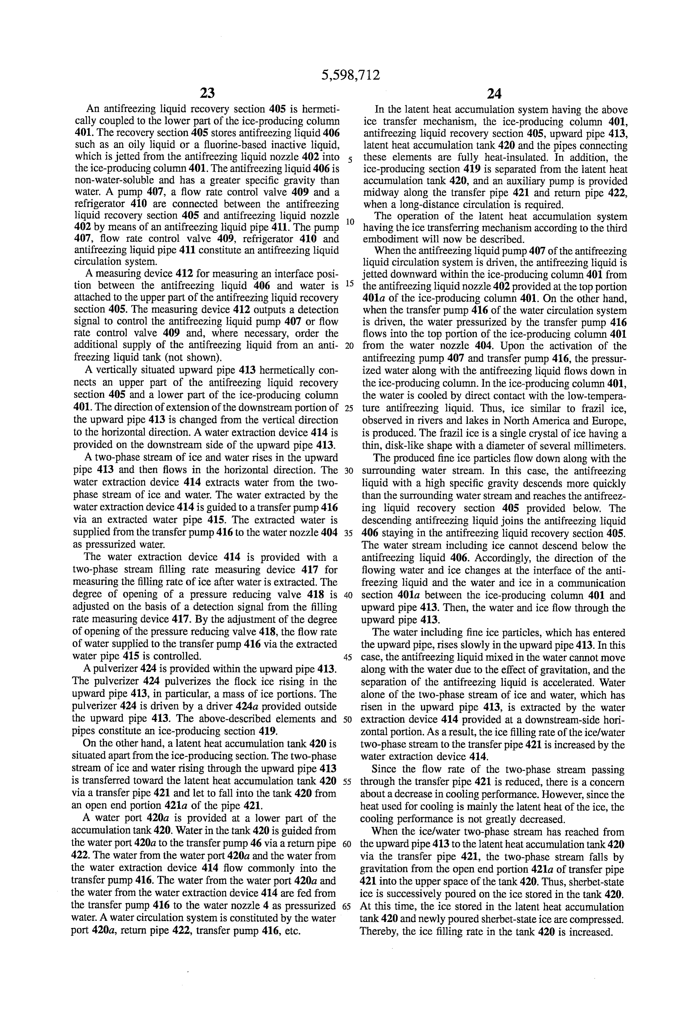
Page 37
The sherbet-state ice staying in the upper part of the latent tank 420. The sherbet-state ice is compressed by gravitation heat accumulation tank 420 is floating on the water. Since and the buoyancy of ice, and the ice-filling rate in the latent the water is guided to the transfer pump 416 via the return heat accumulation tank 420 can be increased. pipe 422 from the water port 420a formed at a lower portion Besides, after the water is extracted by the water extrac of the tank 420, the level of water in the latent heat tion device 414 provided on the downstream side of the accumulation tank 420 having the ice transferring mecha upward pipe 413, the ice filling rate of the two-phase stream nism is kept constant. is measured by the ice filling rate measuring device 417. Although not shown, means for storing and recovering the Based on the measurement signal from the measuring device antifreezing liquid, which is flown out of the ice-producing 4.17, the flow rate of water extracted by the control valve 414 section 419 by the water stream, is provided at bottom 10 is controlled by the pressure reducing valve 418. Thus, the portions of the transfer pipe 421 and latent heat accumula diameter of the water feed pipe and the amount of circulation tion tank 420. Thus, the antifreezing liquid is periodically water in the heat accumulation system can be decreased, and recovered. the manufacturing cost can be reduced. According to the third embodiment of the invention, the FIG. 29 shows a fourth embodiment of a latent heat antifreezing liquid and water are injected from the antifreez 15 accumulation system having an ice transferring mechanism ing liquid nozzle 402 and water nozzle 404 into the top according to the invention. In the system of the fourth portion 401a of ice-producing column 401. Thereby, fine ice embodiment, the water extraction device and extracted particles are produced. The ice particles, along with the water pipe system are removed from the construction shown water and antifreezing liquid, flow down in the ice-produc in FIG. 28. The system of the fourth embodiment includes ing column 401. The antifreezing liquid alone is recovered 20 an ice-producing section 419 in which an ice pulverizer 424 by the antifreezing liquid recovery section 405 provided at is situated within an upward pipe 413. In the system of the the bottom portion of the ice-producing column 401. The ice fourth embodiment, part of the ice/water two-phase stream particles and water rise in the upward pipe 413. The partial produced by the ice-producing section 419 is supplied to a water alone of the ice/water two-phase stream, which has bottom portion of a latent heat accumulation tank 420 via a risen, is extracted by the water extraction device 414. Then, 25 transfer pipe 421. In the system of the fourth embodiment, the two-phase stream is transferred via the transfer pipe 421 the remaining portion of the two-phase stream produced by to the latent heat accumulation tank 420 situated apart from the ice-producing section 419 is transferred to heat exchang the ice-producing column 401. ers 423 for utilization of cold heat. After the cold heat has Accordingly, in the ice-producing column 401, the ice been used, the water of the ice/water two-phase stream is let particles can be efficiently produced by direct contact 30 to flow through a return pipe 422 and to join water drained between the water and antifreezing liquid. In addition, the from the tank 420 through a water port 420a by a transfer antifreezing liquid can be efficiently recovered to the anti pump 416b. The confluent water stream is guided to a freezing liquid recovery section 405 on the basis of the transfer pump 416 provided on the ice-producing section difference in specific gravity between the water and anti (419) side.
freezing liquid. 35 According to the latent heat accumulation system with the The direction of the waterlice stream changes towards the ice-transferring mechanism having the above structure, a upward pipe 413 at the interface of the waterlice stream and large-scale latent heat accumulation tank 420 is not required the antifreezing liquid staying in the antifreezing liquid and the heat accumulation effect can be exhibited only by recovery section 405. In the upward pipe 413, too, the providing the heat exchangers 423 with a small ice reservoir antifreezing liquid is separated from the water by gravitation 40 423a. In addition, the ice-pulverizer 424 is driven by driver and recovered to the antifreezing liquid recovery section 424a so that the outflow of the antifreezing liquid from the 405. Thus, the amount of the antifreezing liquid, which ice-producing unit 419 can be further reduced. flows to the downstream side from the upward pipe 413, is Needless to say, in the case where the ice-producing limited to a minimum, and the ice production can be stably section 419 is situated far away from the heat exchangers continued. In addition, since the pulverizer 424 is driven by 45 423, a water extraction device can also be used, like the third the driver 424a, the outflow of the antifreezing liquid from embodiment.
the ice-producing section 419 is prevented more surely. As regards the third and fourth embodiments, descriptions After the water of the ice/water two-phase stream, which were given of the structure for guiding the two-phase stream has passed through the upward pipe 413, is extracted by the from the ice-producing section 419, which comprises the water extraction device 414, the ice/water two-phase stream 50 ice-producing column 401, antifreezing liquid recovery sec is transferred through the transfer pipe 421 and stored in the tion 405, upward pipe 413 and water extraction device 414, latentheat accumulation tank 420. At this time, the ice/water to the latent heat accumulation tank 420 or heat exchangers two-phase stream is transferred through the sealed and 423. However, it is possible to provide a plurality of heat-insulated pipe. Thus, even if the latent heat accumula ice-producing sections 419, combine ice/water two-phase tion tank 420 is situated far away from the ice-producing 55 streams produced by the respective ice-producing sections tank 419 or the flow rate of the two-phase stream is reduced, 419 by means of a header, and then guide the combined the amount of cold heat is little decreased. Furthermore, the stream to a specified latent heat accumulation tank or a ice-producing column 401, antifreezing liquid recovery sec specified heat exchanger.
tion 405, upward pipe 413 and transfer pipe 421 for the FIG. 30 shows a fifth embodiment of a latent heat ice/water two-phase stream are all connected hermetically, 60 accumulation system having an ice transferring mechanism and the ice/water two-phase stream is continuously fed by according to the invention. In FIG. 30, the same structural the transfer pump 416. Thus, a regular pipe member can be elements as shown in FIG. 28 are denoted by like reference used for the transfer pipe 421 up to the open end thereof. numerals and a description thereof is omitted. The two-phase stream, which has reached the heat accu In the fifth embodiment, an antifreezing liquid recovery mulation tank 420 via the transfer pipe 421, falls into the 65 section 405 is formed in a bottom portion of a vertically space of the tank 420 from the open end portion 421a of the situated upward pipe 13, as shown in FIG. 30. An ice transfer pipe 421 situated above the latentheat accumulation producing column 401 is vertically provided within the
Page 38
upward pipe 413, with an open end portion of the ice and said solid phase material within the production producing column 401 directed to the antifreezing liquid tank;
recovery section 405. An antifreezing liquid circulation a transfer pipe, connected to said upward pipe, for trans system is provided between a top portion of the ice-produc ferring said two-phase stream to a specified place; ing column 401 and the antifreezing liquid recovery section 405. The antifreezing liquid circulation system pressurizes a reservoir tank for storing the two-phase stream trans an antifreezing liquid 406 recovered in the recovery section ferred via said transfer pipe; 405 by means of an antifreezing liquid pump 407 and injects a first fluid circulation system for draining the first fluid the pressurized antifreezing liquid 406 into the ice-produc from the reservoir tank and introducing the drained first ing column 401. 10 fluid into the production tank; and A pulverizer 424 for pulverizing ice, in particular, a flock a second fluid circulation system for cooling the second ice particles, rising in the upward pipe 413, is provided fluid recovered by said recovery section and feeding the within the upward pipe 413. A water extraction device 414 cooled second fluid into the production tank for bring is provided on the downstream side of the pulverizer 424. ing the second fluid into direct contact with the first A transfer pipe 421 is hermetically connected to the 15 fluid.
upward pipe 413 provided on the rear stage of the water extraction device 414. Thus, the ice/water two-phase stream 2. The system according to claim 1, wherein said produc fed through the transfer pipe 421 can be supplied to the tion tank, said recovery section, said upward pipe and said latent heat accumulation tank 420 situated remote from the transfer pipe are hermetically connected. ice-producing section. 20 3. The system according to claim 1, wherein said produc Besides, the latentheat accumulation tank 420 is provided tion tank includes at an upper part thereof a direct contact with a water circulation system. In the water circulation section for direct contact between the first fluid and the system, water drained from the water port through a return second fluid, and at a lower part thereof a coupling section pipe 422 is pressurized by a transfer pump 416 and fed into for coupling with a lower opening portion of the upward the ice-producing column 401 from the top portion thereof. 25 pipe.
Further, in the water circulation system, the water extracted 4. The system according to claim 1, wherein said produc from the water extraction device 414 via an extracted water tion tank is situated within said upward pipe. pipe 415 is let to flow into the return pipe 422. 5. The system according to claim 1, wherein said produc According to the latent heat accumulation system with the tion tank includes a nozzle for injecting the second fluid into ice-transferring mechanism having the above structure, the 30 the first fluid within the production tank, thereby to produce same advantages as in the second and third embodiments said solid phase material, said nozzle being situated in a can be obtained. In addition, since the ice-producing column preset position at a predetermined distance above the inter 401 is provided in the upward pipe 413, the size of the face between the first fluid and the second fluid within the ice-producing section can be reduced and the space for production tank so as to obtain a maximum heat exchange installation made smaller. 35
As has been described above, according to the present efficiency between the first fluid and the second fluid. invention, there is provided a latent heat accumulation 6. The system according to claim 1, further comprising a system having an ice-transferring mechanism including a first fluid extraction section for extracting the first fluid alone highly reliable, highly efficient latent heat transfer system from the upward pipe and introducing the extracted first capable of smoothly feeding sherbet-state ice into a pipe and 40 fluid into the first fluid circulation system. transferring the ice by means of a pump. 7. The system according to claim 1, wherein said first fluid Additional advantages and modifications will readily circulation system includes a pressurizing pump for pres occur to those skilled in the art. Therefore, the invention in surizing the extracted first fluid. its broader aspects is not limited to the specific details, and 8. The system according to claim 1, further comprising representative devices, shown and described herein. Accord 45 pulverizing means for pulverizing said solid state material, ingly, various modifications may be made without departing said pulverizing means being situated within said upward from the spirit or scope of the general inventive concept as plpe.
defined by the appended claims and their equivalents. 9. The system according to claim 1, wherein said second What is claimed is: fluid circulation system includes a pressurizing pump for 1. A latent heat accumulation system having a transfer 50 pressurizing the recovered second fluid.
mechanism, said system comprising: 10. The system according to claim 1, further comprising
a production tank in which a first fluid is put in direct reservoir heat exchange system for draining the first fluid from said contact with a second fluid, which does not combine tank and utilizing the drained first fluid as a heat with the first fluid, has a specific gravity greater than exchange 11. The medium.
system according to claim 10, wherein said heat that of the first fluid and is cooled to a preset tempera exchange system
comprises a heat exchanger into which the ture level, thus producing a solid phase material of the first fluid is supplied from the reservoir tank as a heat first fluid;
a recovery section, formed at a lower part of said pro from exchange medium, and means for draining the first fluid the reservoir tank, introducing the drained first fluid duction tank, for recovering the second fluid descend 60 into the heat exchanger, and returning the first fluid, which ing within the production tank; has flowed out of the heat exchanger, to the reservoir tank. an upward pipe, connected to said production tank, for guiding upward a two-phase stream of said first fluid ck k k k k
Page 39
UNITED STATES PATENT AND TRADEMARK OFFICE
CERTIFICATE OF CORRECTION
INVENTOR(S) : Yutaka WATANABE, et al.
it is certified that error appears in the above-indentified patent and that said Letters Patent is hereby Corrected as shown below:
On the title page, the Foreign Application Priority Data should read:
Signed and Sealed this
Tenth Day of June, 1997
BRUCE LEHMAN
Attesting Officer Commissioner of Patents and Trademarks
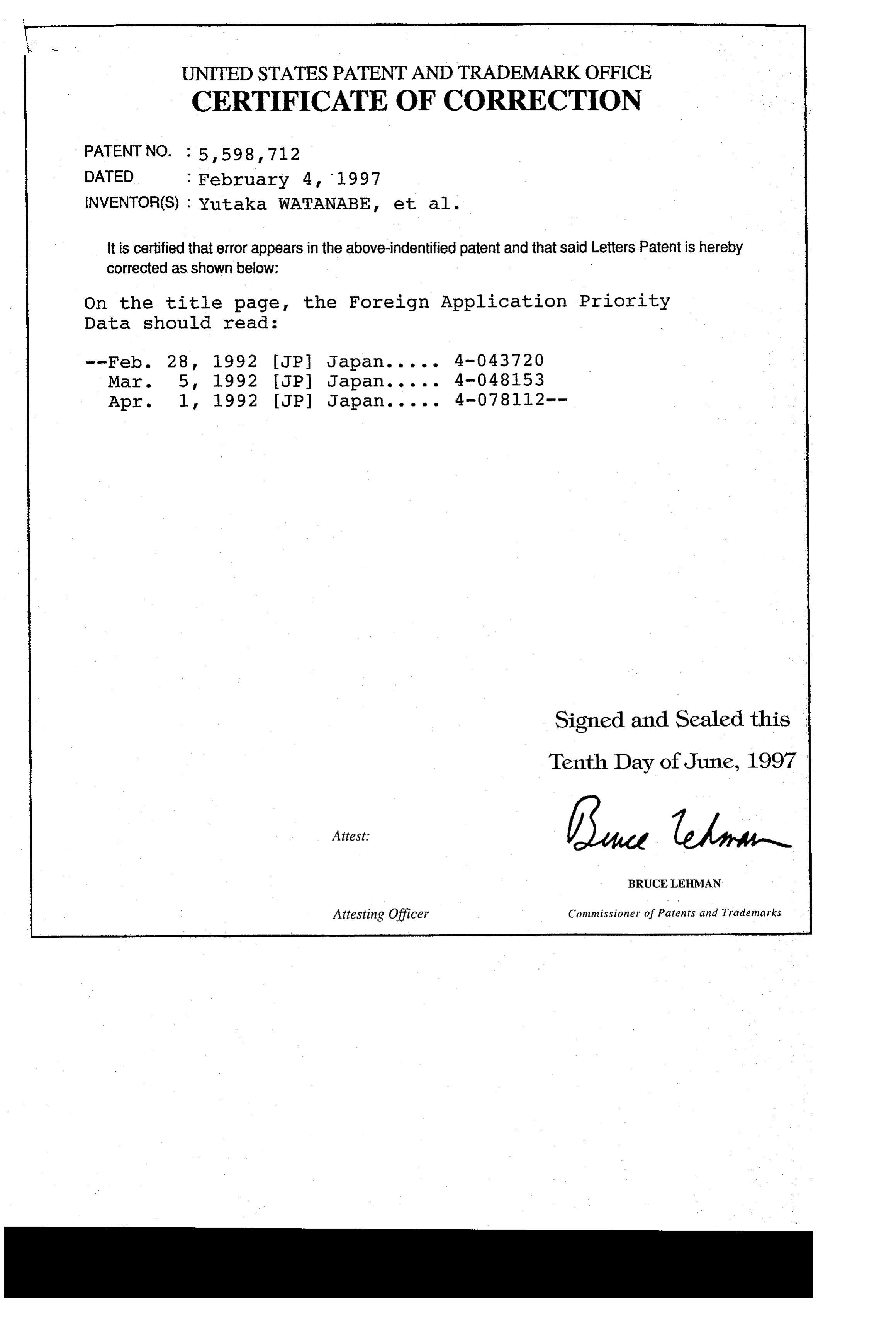
Provenance
- Collection
- Cited prior art
- Original PDF
- patentimages.storage.googleapis.com →
- Filed
- 1995-08-15
- Pages
- 39
- Method
- pdftotext (the PDF's own text layer) + pdftoppm 300dpi page scans
- Source
- Google Patents bibliographic record
- Granted
- 1997-02-04
- Inventors
- Yutaka Watanabe; Takayuki Hachimonji; Katsuya Yamashita; Sanae Sekita; Tsuyoshi Noma; Toshiba Corp
- Transcribed from
- patentimages.storage.googleapis.com →